EP3857060B1 - Procédé de fabrication d'une structure de tour d'éolienne pour empêcher le détachement de tourbillons - Google Patents
Procédé de fabrication d'une structure de tour d'éolienne pour empêcher le détachement de tourbillons Download PDFInfo
- Publication number
- EP3857060B1 EP3857060B1 EP18792659.7A EP18792659A EP3857060B1 EP 3857060 B1 EP3857060 B1 EP 3857060B1 EP 18792659 A EP18792659 A EP 18792659A EP 3857060 B1 EP3857060 B1 EP 3857060B1
- Authority
- EP
- European Patent Office
- Prior art keywords
- tower structure
- wind turbine
- reinforcement
- printing
- printing device
- Prior art date
- Legal status (The legal status is an assumption and is not a legal conclusion. Google has not performed a legal analysis and makes no representation as to the accuracy of the status listed.)
- Active
Links
Images




Classifications
-
- F—MECHANICAL ENGINEERING; LIGHTING; HEATING; WEAPONS; BLASTING
- F03—MACHINES OR ENGINES FOR LIQUIDS; WIND, SPRING, OR WEIGHT MOTORS; PRODUCING MECHANICAL POWER OR A REACTIVE PROPULSIVE THRUST, NOT OTHERWISE PROVIDED FOR
- F03D—WIND MOTORS
- F03D13/00—Assembly, mounting or commissioning of wind motors; Arrangements specially adapted for transporting wind motor components
- F03D13/10—Assembly of wind motors; Arrangements for erecting wind motors
-
- B—PERFORMING OPERATIONS; TRANSPORTING
- B33—ADDITIVE MANUFACTURING TECHNOLOGY
- B33Y—ADDITIVE MANUFACTURING, i.e. MANUFACTURING OF THREE-DIMENSIONAL [3D] OBJECTS BY ADDITIVE DEPOSITION, ADDITIVE AGGLOMERATION OR ADDITIVE LAYERING, e.g. BY 3D PRINTING, STEREOLITHOGRAPHY OR SELECTIVE LASER SINTERING
- B33Y10/00—Processes of additive manufacturing
-
- B—PERFORMING OPERATIONS; TRANSPORTING
- B33—ADDITIVE MANUFACTURING TECHNOLOGY
- B33Y—ADDITIVE MANUFACTURING, i.e. MANUFACTURING OF THREE-DIMENSIONAL [3D] OBJECTS BY ADDITIVE DEPOSITION, ADDITIVE AGGLOMERATION OR ADDITIVE LAYERING, e.g. BY 3D PRINTING, STEREOLITHOGRAPHY OR SELECTIVE LASER SINTERING
- B33Y70/00—Materials specially adapted for additive manufacturing
-
- B—PERFORMING OPERATIONS; TRANSPORTING
- B33—ADDITIVE MANUFACTURING TECHNOLOGY
- B33Y—ADDITIVE MANUFACTURING, i.e. MANUFACTURING OF THREE-DIMENSIONAL [3D] OBJECTS BY ADDITIVE DEPOSITION, ADDITIVE AGGLOMERATION OR ADDITIVE LAYERING, e.g. BY 3D PRINTING, STEREOLITHOGRAPHY OR SELECTIVE LASER SINTERING
- B33Y80/00—Products made by additive manufacturing
-
- E—FIXED CONSTRUCTIONS
- E04—BUILDING
- E04G—SCAFFOLDING; FORMS; SHUTTERING; BUILDING IMPLEMENTS OR AIDS, OR THEIR USE; HANDLING BUILDING MATERIALS ON THE SITE; REPAIRING, BREAKING-UP OR OTHER WORK ON EXISTING BUILDINGS
- E04G21/00—Preparing, conveying, or working-up building materials or building elements in situ; Other devices or measures for constructional work
- E04G21/02—Conveying or working-up concrete or similar masses able to be heaped or cast
- E04G21/04—Devices for both conveying and distributing
- E04G21/0418—Devices for both conveying and distributing with distribution hose
- E04G21/0445—Devices for both conveying and distributing with distribution hose with booms
- E04G21/0463—Devices for both conveying and distributing with distribution hose with booms with boom control mechanisms, e.g. to automate concrete distribution
-
- E—FIXED CONSTRUCTIONS
- E04—BUILDING
- E04H—BUILDINGS OR LIKE STRUCTURES FOR PARTICULAR PURPOSES; SWIMMING OR SPLASH BATHS OR POOLS; MASTS; FENCING; TENTS OR CANOPIES, IN GENERAL
- E04H12/00—Towers; Masts or poles; Chimney stacks; Water-towers; Methods of erecting such structures
- E04H12/02—Structures made of specified materials
- E04H12/12—Structures made of specified materials of concrete or other stone-like material, with or without internal or external reinforcements, e.g. with metal coverings, with permanent form elements
-
- F—MECHANICAL ENGINEERING; LIGHTING; HEATING; WEAPONS; BLASTING
- F03—MACHINES OR ENGINES FOR LIQUIDS; WIND, SPRING, OR WEIGHT MOTORS; PRODUCING MECHANICAL POWER OR A REACTIVE PROPULSIVE THRUST, NOT OTHERWISE PROVIDED FOR
- F03D—WIND MOTORS
- F03D13/00—Assembly, mounting or commissioning of wind motors; Arrangements specially adapted for transporting wind motor components
- F03D13/20—Arrangements for mounting or supporting wind motors; Masts or towers for wind motors
-
- F—MECHANICAL ENGINEERING; LIGHTING; HEATING; WEAPONS; BLASTING
- F05—INDEXING SCHEMES RELATING TO ENGINES OR PUMPS IN VARIOUS SUBCLASSES OF CLASSES F01-F04
- F05B—INDEXING SCHEME RELATING TO WIND, SPRING, WEIGHT, INERTIA OR LIKE MOTORS, TO MACHINES OR ENGINES FOR LIQUIDS COVERED BY SUBCLASSES F03B, F03D AND F03G
- F05B2230/00—Manufacture
- F05B2230/30—Manufacture with deposition of material
- F05B2230/31—Layer deposition
-
- F—MECHANICAL ENGINEERING; LIGHTING; HEATING; WEAPONS; BLASTING
- F05—INDEXING SCHEMES RELATING TO ENGINES OR PUMPS IN VARIOUS SUBCLASSES OF CLASSES F01-F04
- F05B—INDEXING SCHEME RELATING TO WIND, SPRING, WEIGHT, INERTIA OR LIKE MOTORS, TO MACHINES OR ENGINES FOR LIQUIDS COVERED BY SUBCLASSES F03B, F03D AND F03G
- F05B2230/00—Manufacture
- F05B2230/50—Building or constructing in particular ways
-
- F—MECHANICAL ENGINEERING; LIGHTING; HEATING; WEAPONS; BLASTING
- F05—INDEXING SCHEMES RELATING TO ENGINES OR PUMPS IN VARIOUS SUBCLASSES OF CLASSES F01-F04
- F05B—INDEXING SCHEME RELATING TO WIND, SPRING, WEIGHT, INERTIA OR LIKE MOTORS, TO MACHINES OR ENGINES FOR LIQUIDS COVERED BY SUBCLASSES F03B, F03D AND F03G
- F05B2240/00—Components
- F05B2240/10—Stators
- F05B2240/12—Fluid guiding means, e.g. vanes
- F05B2240/122—Vortex generators, turbulators, or the like, for mixing
-
- F—MECHANICAL ENGINEERING; LIGHTING; HEATING; WEAPONS; BLASTING
- F05—INDEXING SCHEMES RELATING TO ENGINES OR PUMPS IN VARIOUS SUBCLASSES OF CLASSES F01-F04
- F05B—INDEXING SCHEME RELATING TO WIND, SPRING, WEIGHT, INERTIA OR LIKE MOTORS, TO MACHINES OR ENGINES FOR LIQUIDS COVERED BY SUBCLASSES F03B, F03D AND F03G
- F05B2250/00—Geometry
- F05B2250/20—Geometry three-dimensional
- F05B2250/25—Geometry three-dimensional helical
-
- F—MECHANICAL ENGINEERING; LIGHTING; HEATING; WEAPONS; BLASTING
- F05—INDEXING SCHEMES RELATING TO ENGINES OR PUMPS IN VARIOUS SUBCLASSES OF CLASSES F01-F04
- F05B—INDEXING SCHEME RELATING TO WIND, SPRING, WEIGHT, INERTIA OR LIKE MOTORS, TO MACHINES OR ENGINES FOR LIQUIDS COVERED BY SUBCLASSES F03B, F03D AND F03G
- F05B2260/00—Function
- F05B2260/96—Preventing, counteracting or reducing vibration or noise
-
- F—MECHANICAL ENGINEERING; LIGHTING; HEATING; WEAPONS; BLASTING
- F15—FLUID-PRESSURE ACTUATORS; HYDRAULICS OR PNEUMATICS IN GENERAL
- F15D—FLUID DYNAMICS, i.e. METHODS OR MEANS FOR INFLUENCING THE FLOW OF GASES OR LIQUIDS
- F15D1/00—Influencing flow of fluids
- F15D1/002—Influencing flow of fluids by influencing the boundary layer
- F15D1/0025—Influencing flow of fluids by influencing the boundary layer using passive means, i.e. without external energy supply
- F15D1/003—Influencing flow of fluids by influencing the boundary layer using passive means, i.e. without external energy supply comprising surface features, e.g. indentations or protrusions
- F15D1/0035—Influencing flow of fluids by influencing the boundary layer using passive means, i.e. without external energy supply comprising surface features, e.g. indentations or protrusions in the form of riblets
-
- F—MECHANICAL ENGINEERING; LIGHTING; HEATING; WEAPONS; BLASTING
- F15—FLUID-PRESSURE ACTUATORS; HYDRAULICS OR PNEUMATICS IN GENERAL
- F15D—FLUID DYNAMICS, i.e. METHODS OR MEANS FOR INFLUENCING THE FLOW OF GASES OR LIQUIDS
- F15D1/00—Influencing flow of fluids
- F15D1/10—Influencing flow of fluids around bodies of solid material
-
- Y—GENERAL TAGGING OF NEW TECHNOLOGICAL DEVELOPMENTS; GENERAL TAGGING OF CROSS-SECTIONAL TECHNOLOGIES SPANNING OVER SEVERAL SECTIONS OF THE IPC; TECHNICAL SUBJECTS COVERED BY FORMER USPC CROSS-REFERENCE ART COLLECTIONS [XRACs] AND DIGESTS
- Y02—TECHNOLOGIES OR APPLICATIONS FOR MITIGATION OR ADAPTATION AGAINST CLIMATE CHANGE
- Y02E—REDUCTION OF GREENHOUSE GAS [GHG] EMISSIONS, RELATED TO ENERGY GENERATION, TRANSMISSION OR DISTRIBUTION
- Y02E10/00—Energy generation through renewable energy sources
- Y02E10/70—Wind energy
- Y02E10/72—Wind turbines with rotation axis in wind direction
-
- Y—GENERAL TAGGING OF NEW TECHNOLOGICAL DEVELOPMENTS; GENERAL TAGGING OF CROSS-SECTIONAL TECHNOLOGIES SPANNING OVER SEVERAL SECTIONS OF THE IPC; TECHNICAL SUBJECTS COVERED BY FORMER USPC CROSS-REFERENCE ART COLLECTIONS [XRACs] AND DIGESTS
- Y02—TECHNOLOGIES OR APPLICATIONS FOR MITIGATION OR ADAPTATION AGAINST CLIMATE CHANGE
- Y02E—REDUCTION OF GREENHOUSE GAS [GHG] EMISSIONS, RELATED TO ENERGY GENERATION, TRANSMISSION OR DISTRIBUTION
- Y02E10/00—Energy generation through renewable energy sources
- Y02E10/70—Wind energy
- Y02E10/728—Onshore wind turbines
-
- Y—GENERAL TAGGING OF NEW TECHNOLOGICAL DEVELOPMENTS; GENERAL TAGGING OF CROSS-SECTIONAL TECHNOLOGIES SPANNING OVER SEVERAL SECTIONS OF THE IPC; TECHNICAL SUBJECTS COVERED BY FORMER USPC CROSS-REFERENCE ART COLLECTIONS [XRACs] AND DIGESTS
- Y02—TECHNOLOGIES OR APPLICATIONS FOR MITIGATION OR ADAPTATION AGAINST CLIMATE CHANGE
- Y02P—CLIMATE CHANGE MITIGATION TECHNOLOGIES IN THE PRODUCTION OR PROCESSING OF GOODS
- Y02P70/00—Climate change mitigation technologies in the production process for final industrial or consumer products
- Y02P70/50—Manufacturing or production processes characterised by the final manufactured product
Definitions
- the present disclosure relates in general to wind turbine towers, and more particularly to methods of manufacturing wind turbine tower structures for preventing vortex shedding, reducing drag, and/or reinforcing the structures.
- Wind power is considered one of the cleanest, most environmentally friendly energy sources presently available, and wind turbines have gained increased attention in this regard.
- a modern wind turbine typically includes a tower, a generator, a gearbox, a nacelle, and one or more rotor blades.
- the rotor blades capture kinetic energy of wind using known foil principles.
- the rotor blades transmit the kinetic energy in the form of rotational energy so as to turn a shaft coupling the rotor blades to a gearbox, or if a gearbox is not used, directly to the generator.
- the generator then converts the mechanical energy to electrical energy that may be deployed to a utility grid.
- the wind turbine tower is generally constructed of steel tubes, pre-fabricated concrete sections, or combinations thereof. Further, the tubes and/or concrete sections are typically formed off-site, shipped on-site, and then arranged together to erect the tower.
- one manufacturing method includes forming pre-cast concrete rings, shipping the rings to the site, arranging the rings atop one another, and then securing the rings together.
- certain tower manufacturing methods include forming a plurality of arc segments and securing the segments together on site to form the diameter of the tower, e.g. via bolting. Such methods, however, require extensive labor and can be time-consuming.
- Document US2017/016244 A1 describes a method of constructing a tower using a 3D printing apparatus.
- DE202018003615 U discloses the use of 3D printing for manufacturing an airflow modifying element for a tower of a wind turbine.
- cylindrical towers can cause vortex shedding, which generally refers to an oscillating flow that takes place when air flows past the bluff (as opposed to streamlined) body at certain velocities, depending on the size and shape of the tower.
- vortices are created at the back of the body and detach periodically from either side thereof. Therefore, the fluid flow past the body creates alternating low-pressure vortices on the downstream side of the body. If the bluff body is not mounted rigidly and the frequency of vortex shedding matches the resonance frequency of the tower, then the tower can begin to resonate, vibrating with harmonic oscillations driven by the energy of the flow.
- the aerodynamic drag on the tower increases the load on the structure as well as reduces the wind velocity which can have a negative effect on a downwind rotor machine.
- the art is continually seeking improved methods for manufacturing wind turbine towers. Accordingly, the present disclosure is directed to methods for manufacturing wind turbine tower structures that address the aforementioned issues.
- the present disclosure is directed to a method for manufacturing a tower structure of a wind turbine according to claim 1.
- the method includes printing, via an additive printing device, the tower structure of the wind turbine of a cementitious material.
- the method also includes printing, via the additive printing device, one or more additional airflow modifying features, namely a plurality of dimples or a plurality of scallops, on an outer surface the tower structure of the wind turbine so as to reduce and/or prevent vortex shedding, excitation, and/or drag of the tower structure.
- the method includes curing the cementitious material so as to form the tower structure.
- the additional airflow modifying feature(s) may further include strakes, protrusions, one or more coils wrapped at least partially around the tower structure, or combinations thereof.
- the method may include printing, via the additive printing device, the tower structure of the wind turbine of the cementitious material to have a non-cylindrical shape as to further reduce and/or prevent vortex shedding, excitation, and/or drag of the tower structure.
- the method may include embedding one or more reinforcement elements at least partially within the cementitious material at one or more locations of the tower structure.
- embedding the one or more reinforcement elements at least partially within the cementitious material at one or more locations may include printing, via the additive printing device, the reinforcement element(s) within the cementitious material at the one or more locations during printing of the tower structure.
- the reinforcement element(s) may include elongated cables or wires, helical cables or wires, reinforcing bars, metallic or polymeric reinforcing fibers, reinforcing metallic rings couplings, and/or mesh. Such elements can be either statically placed in the tower structure to provide concrete reinforcement or post-tensioned after the cementitious material has cured to put the tower structure into compression.
- the method may include providing one or more molds of the tower structure on a foundation of the wind turbine and printing, via the additive printing device, the tower structure of the wind turbine within the one or more molds. In such embodiments, the method may also include printing, via the additive printing device, the one or more molds of the tower structure.
- the method may include printing the tower structure of the wind turbine on a foundation of the tower structure. Further, the method includes, following the curing of the cementitious material, providing one or more reinforcement cables on an outer surface of the tower structure.
- providing the reinforcement cable(s) on the outer surface of the tower structure may include wrapping the reinforcement cable(s) in the same direction around the tower structure with variable spacing between wraps and tensioning the reinforcement cable(s) on the outer surface of the tower structure to provide a varied compression level to the tower structure.
- providing the reinforcement cable(s) on the outer surface of the tower structure may include wrapping a plurality of reinforcement cables in opposing directions around the tower structure with constant spacing between wraps and tensioning the reinforcement cable(s) on the outer surface of the tower structure to provide a uniform compression level to the tower structure. This compression acts in both the axial (i.e. height) direction as well as the horizontal (i.e. hoop) direction, allowing the cementitious material of the tower structure to be optimized, thereby reducing the amount of cementitious material required in the tower structure as compared to conventional methods.
- providing the one or more reinforcement cables on the outer surface of the tower structure may include pre-tensioning the reinforcement cable(s) before providing the reinforcement cable(s) on the outer surface of the tower structure and releasing the one or more pre-tensioned reinforcement cable(s) after curing the cementitious material.
- providing the reinforcement cable(s) on the outer surface of the tower structure may include printing, via the additive printing device, the reinforcement cable(s) on the outer surface of the tower structure.
- the reinforcement cable(s) may include, for example, solid reinforcing bars, hollow reinforcing bars, pultruded reinforcing bars, and/or mesh. It should be further understood that the method may further include any of the additional features and/or steps as described herein.
- the present disclosure is directed to methods for manufacturing wind turbine towers using automated deposition of cementitious materials via technologies such as additive manufacturing, 3-D Printing, spray deposition, extrusion additive manufacturing, concrete printing, automated fiber deposition, as well as other techniques that utilize computer numeric control and multiple degrees of freedom to deposit material. More specifically, methods of the present disclosure include printing features or alternate geometry in concrete wind turbine towers to eliminate the potential of vortex shedding.
- FIG. 1 illustrates one embodiment of a wind turbine 10 according to the present disclosure.
- the wind turbine 10 includes a tower 12 extending from a foundation 15 or support surface with a nacelle 14 mounted atop the tower 12.
- a plurality of rotor blades 16 are mounted to a rotor hub 18, which is in turn connected to a main flange that turns a main rotor shaft.
- the wind turbine power generation and control components are housed within the nacelle 14.
- the view of FIG. 1 is provided for illustrative purposes only to place the present invention in an exemplary field of use. It should be appreciated that the invention is not limited to any particular type of wind turbine configuration.
- the tower structure 12 may be formed from a plurality of sections 25, 27. More specifically, as shown, the tower structure 12 may have a first tower section 25 and a second tower section 27.
- the illustrated tower 12 defines a circumferential tower wall 20 having an outer surface 22 and an inner surface 24.
- the circumferential tower wall 20 generally defines a hollow interior 26 that is commonly used to house various turbine components (e.g. a power converter, transformer, etc.) along different locations in the tower 12.
- the tower structure 12 is formed, at least in part, using additive manufacturing.
- the tower structure 12 is formed, at least in part, of a cementitious material 28 that may be reinforced with one or more reinforcement elements 30.
- the reinforcement element(s) 30 described herein may include, for example, elongated cables or wires, reinforcing bars (hollow or solid), reinforcing fibers (metallic or polymeric), reinforcing metallic rings (circular, oval, spiral and others as may be relevant) or couplings, mesh, and/or any such structures as may be known in the art to reinforce concrete structures.
- the reinforced tower structure 12 is configured to withstand wind loads that can cause the tower 12 to be susceptible to cracking.
- the cementitious material 28 may include any suitable workable paste that is configured to bind together after curing to form a structure.
- suitable cementitious materials include, for example, concrete, pitch resin, asphalt, clay, cement, cementitious compositions, or similar.
- the illustrated tower structure 12 includes one or more additional airflow modifying features 40 additively printed on the outer surface 22 the tower structure 12 of the wind turbine 10 so as to reduce and/or prevent vortex shedding, excitation, and/or drag of the tower structure 12.
- the additional airflow modifying feature(s) 40 described herein are, according to claim 1, a plurality of dimples or a plurality of scallops, and may further include strakes, protrusions, one or more coils wrapped at least partially around the tower structure 12, or combinations thereof. More specifically, as shown in the illustrated embodiment, the additional airflow modifying feature 40 corresponds to a plurality of scallops.
- Additive manufacturing is generally understood to encompass processes used to synthesize three-dimensional objects in which successive layers of material are formed under computer control to create the objects. As such, objects of almost any size and/or shape can be produced from digital model data. It should further be understood that the additive manufacturing methods of the present disclosure may encompass three degrees of freedom, as well as more than three degrees of freedom such that the printing techniques are not limited to printing stacked two-dimensional layers, but are also capable of printing curved and/or irregular shapes.
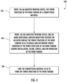
- FIG. 4 a flow diagram of one embodiment of a method 100 for manufacturing a tower structure of a wind turbine at a wind turbine site to reduce and/or prevent vortex shedding, excitation, and/or drag of the tower structure is illustrated.
- the method 100 will be described herein with reference to the wind turbine 10 and the tower structure 12 shown in FIGS. 1-3 .
- the disclosed method 100 may be implemented with tower structures having any other suitable configurations.
- FIG. 4 depicts steps performed in a particular order for purposes of illustration and discussion, the methods discussed herein are not limited to any particular order or arrangement, unless a particular order or arrangement is defined in the claims.
- the method 100 includes printing, via an additive printing device 32, the tower structure 12 of the wind turbine 10 of the cementitious material 28.
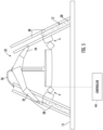
- an additive printing device 32 For example, as shown in FIG. 5 , a schematic diagram of one embodiment of the additive printing device 32 according to the present disclosure is illustrated.
- the additive printing device 32 described herein generally refers to any suitable additive printing device having one or more nozzles for depositing material (such as the cementitious material 28) onto a surface that is automatically controlled by a controller (such as controller 44) to form an object programmed within the computer (such as a CAD file). More specifically, as shown, the additive printing device 32 may include one or more nozzles 34 for depositing various materials.
- the additive printing device 32 includes two nozzles 34.
- the additive printing device 32 may include any suitable number of nozzles 34.
- the additive printing device 32 may include an injector 36, which is discussed in more detail below.
- the method 100 may include providing one or more molds 38 of the tower structure 12, e.g. on the foundation 15 of the wind turbine 10.
- the molds 38 described herein may be solid, porous, and/or printed with openings to inject the cementitious material 38.
- the mold(s) 38 may be prefabricated and delivered to the wind turbine site.
- the additive printing device 32 may also be configured to print the mold(s) 38 of the tower structure 12.
- one of the nozzles 34 may be configured to dispense a polymer material for building up the mold(s) 38 on the foundation 15 of the wind turbine 10 (or any other suitable on-site location).
- Suitable polymer materials may include, for example, a thermoset material, a thermoplastic material, a biodegradable polymer (such as a corn-based polymer system, fungal-like additive material, or an algae-based polymer system) that is configured to degrade/dissolve over time, or combinations thereof.
- a thermoset material such as a corn-based polymer system, fungal-like additive material, or an algae-based polymer system
- a biodegradable polymer such as a corn-based polymer system, fungal-like additive material, or an algae-based polymer system
- the outer polymer mold may be biodegradable over time, whereas the inner polymer mold remains intact.
- the outer and inner molds may be constructed of the same material.
- the additive printing device 32 may be configured to fill the mold(s) 38 of the tower structure 12 with the cementitious material 28. More specifically, as shown, one or more of the nozzles 34 may be configured to print the cementitious material 28 into the molds 38. In alternative embodiments, rather than printing the cementitious material 28, the injector 36 of the additive printing device 32 may simply inject or fill the mold(s) 38 with the cementitious material 28, e.g. by injecting the cementitious material 28 from the top of the molds 38 or by injecting the cementitious material 28 through openings in the mold.
- the method 100 may include embedding one or more of the reinforcement elements 30 at least partially within the cementitious material 28 at one or more locations of the tower structure 12.
- the additive printing device 32 may be configured to print the reinforcement element(s) 30 within the cementitious material 28 at the one or more locations during printing of the tower structure 12.
- the additive printing device 32 is configured to print the cementitious material 28 in a manner that accounts for the cure rate thereof such that the tower structure 12, as it is being formed, can bond to itself.
- the additive printing device 32 is configured to print the tower structure 12 in a manner such that it can withstand the weight of the wall 20 as the additively-formed cementitious material 28 can be weak during printing.
- the method 100 may include printing, via the additive printing device 32, the tower structure 12 to have a non-cylindrical or alternative shape as to further reduce and/or prevent vortex shedding, excitation, and/or drag of the tower structure 12.
- the method 100 may also includes printing, via the additive printing device 32, one or more of the additional airflow modifying features 40 on the outer surface 22 the tower structure 12 of the wind turbine 10 so as to reduce and/or prevent vortex shedding, excitation, and/or drag of the tower structure 12.
- the additional airflow modifying feature(s) 40 described herein are, according to claim 1, a plurality of dimples or a plurality of scallops, and may further include strakes, protrusions, one or more coils wrapped at least partially around the tower structure 12, or combinations thereof.
- the method 100 further includes curing the cementitious material 28 so as to form the tower structure 12.
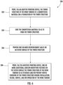
- FIG. 6 a flow diagram of another embodiment of a method 200 for manufacturing a tower structure of a wind turbine at a wind turbine site to reduce and/or prevent vortex shedding, excitation, and/or drag of the tower structure is illustrated.
- the method 200 will be described herein with reference to the wind turbine 10 and the tower structure 12 shown in FIGS. 1-3 .
- the disclosed method 200 may be implemented with tower structures having any other suitable configurations.
- FIG. 6 depicts steps performed in a particular order for purposes of illustration and discussion, the methods discussed herein are not limited to any particular order or arrangement, unless a particular order or arrangement is defined in the claims.
- the method 200 may include printing, via the additive printing device 32, the tower structure 12 of the wind turbine 10 of the cementitious material 28 on a foundation of the tower structure 12, such as the foundation 15 of the wind turbine 10.
- the additive printing device 32 is configured to print the tower structure 12 of the cementitious material 28.
- the method 200 may include curing the cementitious material 28 so as to form the tower structure 12.
- the method 200 may include providing one or more reinforcement cables 30 on the outer surface 22 of the tower structure 12.
- the additive printing device 32 may be configured to print the reinforcement cable(s) 30 on the outer surface 22 of the tower structure 12.
- the reinforcement cable(s) 30 may include, for example, solid reinforcing bars, hollow reinforcing bars, pultruded reinforcing bars, and/or mesh.
- the reinforcement cable(s) 30 may be constructed of any suitable material, including for example, a metal or metal alloy (such as steel), a composite material, basalt, or similar.
- the method 200 may include wrapping the reinforcement cable(s) 30 in the same direction around the tower structure 12 with variable spacing between wraps and tensioning the reinforcement cable(s) 30 on the outer surface 22 of the tower structure 12 to provide a varied compression level to the tower structure 12.
- the method 200 may include wrapping a plurality of the reinforcement cables 30 in opposing directions around the tower structure 12 with constant spacing between wraps and tensioning the reinforcement cable(s) 30 on the outer surface 22 of the tower structure 12 to provide a uniform compression level to the tower structure 12. More specifically, as shown in FIG. 9 , opposing reinforcement cable(s) 0 may be double-sided printed from a vertically-extending rebar.
- the reinforcement cables 30 provide compression in the hoop and elevation directions.
- the method 200 may include pre-tensioning the reinforcement cable(s) 30 before providing the reinforcement cable(s) 30 on the outer surface 22 of the tower structure 12 and releasing the pre-tensioned reinforcement cable(s) 30 after curing the cementitious material 28.
- the method 200 includes printing, via the additive printing device 32, one or more of the additional airflow modifying features 40 on the outer surface 22 the tower structure 12 of the wind turbine 10 so as to reduce and/or prevent vortex shedding, excitation, and/or drag of the tower structure 12 during installation, idling, service, or operation of the wind turbine 10, wherein, according to claim 1, the one or more additional airflow modifying features are a plurality of dimples or a plurality of scallops.
- the controller 44 may include one or more processor(s) 46 and associated memory device(s) 48 configured to perform a variety of computer-implemented functions (e.g., performing the methods, steps, calculations and the like and storing relevant data as disclosed herein). Additionally, the controller 44 may also include a communications module 50 to facilitate communications between the controller 44 and the various components of the additive printing device 32. Further, the communications module 50 may include a sensor interface 52 (e.g., one or more analog-to-digital converters) to permit signals transmitted from one or more sensors to be converted into signals that can be understood and processed by the processors 46. It should be appreciated that the sensors may be communicatively coupled to the communications module 50 using any suitable means, including e.g. a wired connection and a wireless connection, such as by using any suitable wireless communications protocol known in the art.
- a sensor interface 52 e.g., one or more analog-to-digital converters
- processor refers not only to integrated circuits referred to in the art as being included in a computer, but also refers to a controller, a microcontroller, a microcomputer, a programmable logic controller (PLC), an application specific integrated circuit, and other programmable circuits.
- the processor 46 is also configured to compute advanced control algorithms and communicate to a variety of Ethernet or serial-based protocols (Modbus, OPC, CAN, etc.).
- the memory device(s) 48 may generally comprise memory element(s) including, but not limited to, computer readable medium (e.g., random access memory (RAM)), computer readable non-volatile medium (e.g., a flash memory), a floppy disk, a compact disc-read only memory (CD-ROM), a magnetooptical disk (MOD), a digital versatile disc (DVD) and/or other suitable memory elements.
- RAM random access memory
- RAM computer readable non-volatile medium
- CD-ROM compact disc-read only memory
- MOD magnetooptical disk
- DVD digital versatile disc
Landscapes
- Engineering & Computer Science (AREA)
- Chemical & Material Sciences (AREA)
- Materials Engineering (AREA)
- Architecture (AREA)
- Mechanical Engineering (AREA)
- Manufacturing & Machinery (AREA)
- Life Sciences & Earth Sciences (AREA)
- Sustainable Development (AREA)
- Sustainable Energy (AREA)
- Combustion & Propulsion (AREA)
- General Engineering & Computer Science (AREA)
- Structural Engineering (AREA)
- Civil Engineering (AREA)
- Wood Science & Technology (AREA)
- Wind Motors (AREA)
Claims (15)
- Procédé permettant de fabriquer une structure de tour (12) d'une éolienne (10), le procédé comprenant :l'impression, par l'intermédiaire d'un dispositif d'impression additif (32), de la structure de tour (12) de l'éolienne (10) d'un matériau cimentaire (28) ;l'impression, par l'intermédiaire du dispositif d'impression additif (32), d'un ou de plusieurs éléments supplémentaires de modification de flux d'air (40), à savoir une pluralité d'embrèvements ou une pluralité de festons, sur une surface externe (22) de la structure de tour (12) de l'éolienne (10) de manière à réduire et/ou à empêcher le décollement de tourbillon, l'excitation et/ou la traînée de la structure de tour (12) de l'éolienne (10) pendant l'installation, le fonctionnement au ralenti, le service ou le fonctionnement de l'éolienne (10) ; etle durcissement du matériau cimentaire (28) de manière à former la structure de tour (12) de l'éolienne (10).
- Procédé selon la revendication 1, comprenant en outre :
l'impression, par l'intermédiaire du dispositif d'impression additif (32), d'au moins un élément supplémentaire de modification de flux d'air (40) sur la surface externe (22) de la structure de tour (12) de l'éolienne, l'au moins un élément supplémentaire de modification de flux d'air (40) étant au moins l'un parmi des virures, des saillies, une ou plusieurs bobines enroulées au moins partiellement autour de la structure de tour (12), ou des combinaisons de ceux-ci. - Procédé selon la revendication 1, comprenant en outre l'impression, par l'intermédiaire du dispositif d'impression additif (32), de la structure de tour (12) de l'éolienne (10) du matériau cimentaire (28) pour avoir une forme non cylindrique afin en outre de réduire et/ou d'empêcher le décollement de tourbillon, l'excitation et/ou la traînée de la structure de tour (12).
- Procédé selon la revendication 1, comprenant en outre pendant l'impression, le collage d'une ou de plusieurs pièces de renforcement (30) au moins partiellement à l'intérieur du matériau cimentaire (28) à un ou plusieurs emplacements de la structure de tour (12).
- Procédé selon la revendication 4, dans lequel le collage de la ou des pièces de renforcement (30) au moins partiellement à l'intérieur du matériau cimentaire (28) à un ou plusieurs emplacements comprend en outre l'impression, par l'intermédiaire du dispositif d'impression additif (32), de la ou des pièces de renforcement (30) à l'intérieur du matériau cimentaire (28) à et aux emplacements pendant l'impression de la structure de tour (12).
- Procédé selon la revendication 5, dans lequel la ou les pièces de renforcement (30) comprennent au moins l'un parmi des câbles ou fils allongés, des câbles ou des fils hélicoïdaux, des barres de renforcement, des fibres de renforcement métalliques ou polymères, des accouplements de bagues métalliques de renforcement, et/ou un treillis.
- Procédé selon la revendication 1, comprenant en outre :la fourniture d'un ou de plusieurs moules (38) de la structure de tour (12) sur une fondation (15) de l'éolienne (10) ; et,l'impression, par l'intermédiaire du dispositif d'impression additif (32), de la structure de tour (12) de l'éolienne (10) au sein du ou des moules (38).
- Procédé selon la revendication 7, comprenant en outre l'impression, par l'intermédiaire du dispositif d'impression additif (32), du ou des moules (38) de la structure de tour (12).
- Procédé selon la revendication 1, comprenant en outre :dans lequel la structure de tour (12) de l'éolienne (10) est imprimée sur une fondation (15) de la structure de tour (12) ;après le durcissement du matériau cimentaire (28), la fourniture d'un ou de plusieurs câbles de renforcement (30) sur une surface externe (22) de la structure de tour (12).
- Procédé selon la revendication 9, dans lequel la fourniture du ou des câbles de renforcement (30) sur la surface externe (22) de la structure de tour (12) comprend en outre l'enveloppement du ou des câbles de renforcement (30) dans la même direction autour de la structure de tour (12) avec un espacement variable entre des enroulements, et le tensionnage du ou des câbles de renforcement (30) sur la surface externe (22) de la structure de tour (12) pour fournir un niveau de compression varié à la structure de tour (12).
- Procédé selon la revendication 9, dans lequel la fourniture du ou des câbles de renforcement (30) sur la surface externe (22) de la structure de tour (12) comprend en outre :
l'enroulement d'une pluralité de câbles de renforcement (30) dans des directions opposées autour de la structure de tour (12) avec un espacement constant entre des enroulements, et le tensionnage du ou des câbles de renforcement (30) sur la surface externe (22) de la structure de tour (12) pour fournir un niveau de compression uniforme à la structure de tour (12). - Procédé selon la revendication 9, dans lequel la fourniture du ou des câbles de renforcement (30) sur la surface externe (22) de la structure de tour (12) comprend en outre :la précontrainte par adhérence du ou des câbles de renforcement (30) avant de fournir le ou les câbles de renforcement (30) sur la surface externe (22) de la structure de tour (12) ; et,la libération du ou des câbles de renforcement (30) précontraints par adhérence après durcissement du matériau cimentaire (28).
- Procédé selon la revendication 9, dans lequel la fourniture du ou des câbles de renforcement (30) sur la surface externe (22) de la structure de tour (12) comprend en outre l'impression, par l'intermédiaire du dispositif d'impression additif (32), du ou des câbles de renforcement (30) sur la surface externe (22) de la structure de tour (12).
- Procédé selon la revendication 9, dans lequel le ou les câbles de renforcement (30) comprennent au moins l'un parmi des barres de renforcement solides, des barres de renforcement creuses, des barres de renforcement pultrudées, et/ou un treillis.
- Procédé selon la revendication 9, comprenant en outre :
l'impression, par l'intermédiaire du dispositif d'impression additif (32), d'au moins un élément supplémentaire de modification de flux d'air (40) sur la surface externe (22) de la structure de tour (12) de l'éolienne (10), l'au moins un élément supplémentaire de modification de flux d'air (40) étant au moins l'un parmi des virures, des saillies, une ou plusieurs bobines enroulées au moins partiellement autour de la structure de tour (12), ou des combinaisons de ceux-ci.
Applications Claiming Priority (1)
| Application Number | Priority Date | Filing Date | Title |
|---|---|---|---|
| PCT/US2018/053477 WO2020068124A1 (fr) | 2018-09-28 | 2018-09-28 | Procédé de fabrication d'une structure de tour d'éolienne pour empêcher le détachement de tourbillons |
Publications (3)
| Publication Number | Publication Date |
|---|---|
| EP3857060A1 EP3857060A1 (fr) | 2021-08-04 |
| EP3857060B1 true EP3857060B1 (fr) | 2023-11-15 |
| EP3857060B8 EP3857060B8 (fr) | 2024-01-03 |
Family
ID=63963455
Family Applications (1)
| Application Number | Title | Priority Date | Filing Date |
|---|---|---|---|
| EP18792659.7A Active EP3857060B8 (fr) | 2018-09-28 | 2018-09-28 | Procédé de fabrication d'une structure de tour d'éolienne pour empêcher le détachement de tourbillons |
Country Status (6)
| Country | Link |
|---|---|
| US (1) | US12000373B2 (fr) |
| EP (1) | EP3857060B8 (fr) |
| CN (1) | CN113056604A (fr) |
| DK (1) | DK3857060T3 (fr) |
| ES (1) | ES2971420T3 (fr) |
| WO (1) | WO2020068124A1 (fr) |
Families Citing this family (5)
| Publication number | Priority date | Publication date | Assignee | Title |
|---|---|---|---|---|
| CN118056055A (zh) * | 2021-10-05 | 2024-05-17 | 通用电气可再生能源西班牙有限公司 | 用于制造塔架结构的系统和方法 |
| US12529239B2 (en) * | 2022-10-31 | 2026-01-20 | Ge Infrastructure Technology Llc | Wind turbine tower structure with stacked tower sections |
| US12264490B2 (en) | 2022-11-16 | 2025-04-01 | Ge Infrastructure Technology Llc | System and method for manufacturing a tower structure |
| US12129835B1 (en) | 2024-03-27 | 2024-10-29 | Purus Power Corporation | Vehicular wind turbine system for drag reduction |
| US12234810B1 (en) | 2024-09-25 | 2025-02-25 | Purus Power Corporation | Wind turbine system for power generation |
Family Cites Families (13)
| Publication number | Priority date | Publication date | Assignee | Title |
|---|---|---|---|---|
| US20110138704A1 (en) | 2010-06-30 | 2011-06-16 | General Electric Company | Tower with tensioning cables |
| US9162399B2 (en) | 2010-09-22 | 2015-10-20 | Composite Rebat Technologies, Inc. | Hollow, composite-material rebar structure, associated components, and fabrication apparatus and methodology |
| DE102011078016A1 (de) | 2011-06-22 | 2012-12-27 | Aloys Wobben | Turmfertigung |
| US9567981B2 (en) | 2011-09-30 | 2017-02-14 | Siemens Aktiengesellschaft | Wind turbine tower and method of production thereof |
| DK2735674T3 (en) * | 2012-11-21 | 2016-01-11 | Siemens Ag | Sliding shell concrete tower |
| WO2015131174A1 (fr) * | 2014-02-28 | 2015-09-03 | University Of Maine System Board Of Trustees | Tour de béton composite hybride pour une éolienne et procédé de fabrication |
| WO2016044669A1 (fr) | 2014-09-17 | 2016-03-24 | Composite Rebar Technologies, Inc. | Structure de barre d'armature composite creuse, méthodologie de fabrication associée, et appareil |
| DK3029313T3 (en) * | 2014-12-04 | 2018-05-07 | Siemens Ag | Strake for a windmill tower |
| EP3118394B1 (fr) * | 2015-07-13 | 2022-05-25 | Siemens Gamesa Renewable Energy A/S | Procédé de construction d'une tour et appareil impression 3d pour tour |
| US11098691B2 (en) | 2017-02-03 | 2021-08-24 | General Electric Company | Methods for manufacturing wind turbine rotor blades and components thereof |
| CN107461302B (zh) | 2017-09-11 | 2018-10-02 | 北京金风科创风电设备有限公司 | 外表面具有抑制涡激振动功能的围护结构 |
| CN207229307U (zh) * | 2017-09-11 | 2018-04-13 | 北京金风科创风电设备有限公司 | 具有凸凹外表面以抑制涡激振动的围护结构 |
| DE202018003615U1 (de) * | 2018-08-03 | 2018-08-13 | Christin Jensen | Scruton-Spirale |
-
2018
- 2018-09-28 US US17/279,115 patent/US12000373B2/en active Active
- 2018-09-28 WO PCT/US2018/053477 patent/WO2020068124A1/fr not_active Ceased
- 2018-09-28 CN CN201880099835.3A patent/CN113056604A/zh active Pending
- 2018-09-28 EP EP18792659.7A patent/EP3857060B8/fr active Active
- 2018-09-28 ES ES18792659T patent/ES2971420T3/es active Active
- 2018-09-28 DK DK18792659.7T patent/DK3857060T3/da active
Also Published As
| Publication number | Publication date |
|---|---|
| CN113056604A (zh) | 2021-06-29 |
| EP3857060A1 (fr) | 2021-08-04 |
| DK3857060T3 (da) | 2024-02-19 |
| ES2971420T3 (es) | 2024-06-05 |
| US20210396213A1 (en) | 2021-12-23 |
| US12000373B2 (en) | 2024-06-04 |
| EP3857060B8 (fr) | 2024-01-03 |
| WO2020068124A1 (fr) | 2020-04-02 |
Similar Documents
| Publication | Publication Date | Title |
|---|---|---|
| EP3857060B1 (fr) | Procédé de fabrication d'une structure de tour d'éolienne pour empêcher le détachement de tourbillons | |
| EP3856485B1 (fr) | Procédé de fabrication d'une structure de tour d'éolienne télescopique | |
| EP3857057B1 (fr) | Procédé de fabrication d'une structure de la tour d'éolienne sur la base de la direction du vent | |
| US11970875B2 (en) | Multi-head additive printing device for manufacturing wind turbine tower structure | |
| EP3857055B1 (fr) | Procédé de fabrication d'une structure de tour d'éolienne avec éléments de détection de renforcement incorporés | |
| US12281483B2 (en) | System and method for manufacturing a tower structure | |
| EP4008511B1 (fr) | Procédé de fabrication d'une structure de tour | |
| EP3857056B1 (fr) | Procédés de fabrication d'une structure de tour d'éolienne à l'aide de matériaux ayant des vitesses de durcissement différentes | |
| CN101920538A (zh) | 复合式风力涡轮机塔架的竖直制造 | |
| JP2022520939A (ja) | ハイブリッドタワーセクション、風力発電所用のハイブリッドタワーとその製造方法 | |
| US11939762B2 (en) | System and method for manufacturing a tower structure | |
| US20230135211A1 (en) | Additively manufactured structure with reinforced access opening |
Legal Events
| Date | Code | Title | Description |
|---|---|---|---|
| STAA | Information on the status of an ep patent application or granted ep patent |
Free format text: STATUS: UNKNOWN |
|
| STAA | Information on the status of an ep patent application or granted ep patent |
Free format text: STATUS: THE INTERNATIONAL PUBLICATION HAS BEEN MADE |
|
| PUAI | Public reference made under article 153(3) epc to a published international application that has entered the european phase |
Free format text: ORIGINAL CODE: 0009012 |
|
| STAA | Information on the status of an ep patent application or granted ep patent |
Free format text: STATUS: REQUEST FOR EXAMINATION WAS MADE |
|
| 17P | Request for examination filed |
Effective date: 20210427 |
|
| AK | Designated contracting states |
Kind code of ref document: A1 Designated state(s): AL AT BE BG CH CY CZ DE DK EE ES FI FR GB GR HR HU IE IS IT LI LT LU LV MC MK MT NL NO PL PT RO RS SE SI SK SM TR |
|
| DAV | Request for validation of the european patent (deleted) | ||
| DAX | Request for extension of the european patent (deleted) | ||
| RIC1 | Information provided on ipc code assigned before grant |
Ipc: F15D 1/10 20060101ALN20221117BHEP Ipc: F15D 1/00 20060101ALN20221117BHEP Ipc: E04G 21/04 20060101ALI20221117BHEP Ipc: B33Y 70/00 20200101ALI20221117BHEP Ipc: B33Y 10/00 20150101ALI20221117BHEP Ipc: B33Y 80/00 20150101ALI20221117BHEP Ipc: F03D 13/10 20160101ALI20221117BHEP Ipc: F03D 13/20 20160101AFI20221117BHEP |
|
| RIC1 | Information provided on ipc code assigned before grant |
Ipc: F15D 1/10 20060101ALN20221124BHEP Ipc: F15D 1/00 20060101ALN20221124BHEP Ipc: E04G 21/04 20060101ALI20221124BHEP Ipc: B33Y 70/00 20200101ALI20221124BHEP Ipc: B33Y 10/00 20150101ALI20221124BHEP Ipc: B33Y 80/00 20150101ALI20221124BHEP Ipc: F03D 13/10 20160101ALI20221124BHEP Ipc: F03D 13/20 20160101AFI20221124BHEP |
|
| GRAP | Despatch of communication of intention to grant a patent |
Free format text: ORIGINAL CODE: EPIDOSNIGR1 |
|
| STAA | Information on the status of an ep patent application or granted ep patent |
Free format text: STATUS: GRANT OF PATENT IS INTENDED |
|
| INTG | Intention to grant announced |
Effective date: 20230105 |
|
| GRAJ | Information related to disapproval of communication of intention to grant by the applicant or resumption of examination proceedings by the epo deleted |
Free format text: ORIGINAL CODE: EPIDOSDIGR1 |
|
| STAA | Information on the status of an ep patent application or granted ep patent |
Free format text: STATUS: REQUEST FOR EXAMINATION WAS MADE |
|
| GRAP | Despatch of communication of intention to grant a patent |
Free format text: ORIGINAL CODE: EPIDOSNIGR1 |
|
| STAA | Information on the status of an ep patent application or granted ep patent |
Free format text: STATUS: GRANT OF PATENT IS INTENDED |
|
| INTC | Intention to grant announced (deleted) | ||
| RIC1 | Information provided on ipc code assigned before grant |
Ipc: F15D 1/10 20060101ALN20230509BHEP Ipc: F15D 1/00 20060101ALN20230509BHEP Ipc: E04G 21/04 20060101ALI20230509BHEP Ipc: B33Y 70/00 20200101ALI20230509BHEP Ipc: B33Y 10/00 20150101ALI20230509BHEP Ipc: B33Y 80/00 20150101ALI20230509BHEP Ipc: F03D 13/10 20160101ALI20230509BHEP Ipc: F03D 13/20 20160101AFI20230509BHEP |
|
| INTG | Intention to grant announced |
Effective date: 20230612 |
|
| P01 | Opt-out of the competence of the unified patent court (upc) registered |
Effective date: 20230530 |
|
| GRAS | Grant fee paid |
Free format text: ORIGINAL CODE: EPIDOSNIGR3 |
|
| GRAA | (expected) grant |
Free format text: ORIGINAL CODE: 0009210 |
|
| STAA | Information on the status of an ep patent application or granted ep patent |
Free format text: STATUS: THE PATENT HAS BEEN GRANTED |
|
| AK | Designated contracting states |
Kind code of ref document: B1 Designated state(s): AL AT BE BG CH CY CZ DE DK EE ES FI FR GB GR HR HU IE IS IT LI LT LU LV MC MK MT NL NO PL PT RO RS SE SI SK SM TR |
|
| REG | Reference to a national code |
Ref country code: CH Ref legal event code: EP Ref country code: GB Ref legal event code: FG4D |
|
| REG | Reference to a national code |
Ref country code: DE Ref legal event code: R081 Ref document number: 602018061168 Country of ref document: DE Owner name: GENERAL ELECTRIC RENOVABLES ESPANA S.L., ES Free format text: FORMER OWNER: GENERAL ELECTRIC COMPANY, SCHENECTADY, NY, US |
|
| REG | Reference to a national code |
Ref country code: DE Ref legal event code: R096 Ref document number: 602018061168 Country of ref document: DE |
|
| REG | Reference to a national code |
Ref country code: IE Ref legal event code: FG4D |
|
| RAP2 | Party data changed (patent owner data changed or rights of a patent transferred) |
Owner name: GENERAL ELECTRIC RENOVABLES ESPANA, S.L. |
|
| REG | Reference to a national code |
Ref country code: CH Ref legal event code: PK Free format text: BERICHTIGUNG B8 |
|
| REG | Reference to a national code |
Ref country code: DK Ref legal event code: T3 Effective date: 20240213 |
|
| REG | Reference to a national code |
Ref country code: LT Ref legal event code: MG9D |
|
| REG | Reference to a national code |
Ref country code: NL Ref legal event code: MP Effective date: 20231115 |
|
| PG25 | Lapsed in a contracting state [announced via postgrant information from national office to epo] |
Ref country code: GR Free format text: LAPSE BECAUSE OF FAILURE TO SUBMIT A TRANSLATION OF THE DESCRIPTION OR TO PAY THE FEE WITHIN THE PRESCRIBED TIME-LIMIT Effective date: 20240216 |
|
| PG25 | Lapsed in a contracting state [announced via postgrant information from national office to epo] |
Ref country code: IS Free format text: LAPSE BECAUSE OF FAILURE TO SUBMIT A TRANSLATION OF THE DESCRIPTION OR TO PAY THE FEE WITHIN THE PRESCRIBED TIME-LIMIT Effective date: 20240315 |
|
| PG25 | Lapsed in a contracting state [announced via postgrant information from national office to epo] |
Ref country code: LT Free format text: LAPSE BECAUSE OF FAILURE TO SUBMIT A TRANSLATION OF THE DESCRIPTION OR TO PAY THE FEE WITHIN THE PRESCRIBED TIME-LIMIT Effective date: 20231115 |
|
| REG | Reference to a national code |
Ref country code: AT Ref legal event code: MK05 Ref document number: 1631993 Country of ref document: AT Kind code of ref document: T Effective date: 20231115 |
|
| PG25 | Lapsed in a contracting state [announced via postgrant information from national office to epo] |
Ref country code: NL Free format text: LAPSE BECAUSE OF FAILURE TO SUBMIT A TRANSLATION OF THE DESCRIPTION OR TO PAY THE FEE WITHIN THE PRESCRIBED TIME-LIMIT Effective date: 20231115 |
|
| PG25 | Lapsed in a contracting state [announced via postgrant information from national office to epo] |
Ref country code: AT Free format text: LAPSE BECAUSE OF FAILURE TO SUBMIT A TRANSLATION OF THE DESCRIPTION OR TO PAY THE FEE WITHIN THE PRESCRIBED TIME-LIMIT Effective date: 20231115 |
|
| PG25 | Lapsed in a contracting state [announced via postgrant information from national office to epo] |
Ref country code: NL Free format text: LAPSE BECAUSE OF FAILURE TO SUBMIT A TRANSLATION OF THE DESCRIPTION OR TO PAY THE FEE WITHIN THE PRESCRIBED TIME-LIMIT Effective date: 20231115 Ref country code: LT Free format text: LAPSE BECAUSE OF FAILURE TO SUBMIT A TRANSLATION OF THE DESCRIPTION OR TO PAY THE FEE WITHIN THE PRESCRIBED TIME-LIMIT Effective date: 20231115 Ref country code: IS Free format text: LAPSE BECAUSE OF FAILURE TO SUBMIT A TRANSLATION OF THE DESCRIPTION OR TO PAY THE FEE WITHIN THE PRESCRIBED TIME-LIMIT Effective date: 20240315 Ref country code: GR Free format text: LAPSE BECAUSE OF FAILURE TO SUBMIT A TRANSLATION OF THE DESCRIPTION OR TO PAY THE FEE WITHIN THE PRESCRIBED TIME-LIMIT Effective date: 20240216 Ref country code: BG Free format text: LAPSE BECAUSE OF FAILURE TO SUBMIT A TRANSLATION OF THE DESCRIPTION OR TO PAY THE FEE WITHIN THE PRESCRIBED TIME-LIMIT Effective date: 20240215 Ref country code: AT Free format text: LAPSE BECAUSE OF FAILURE TO SUBMIT A TRANSLATION OF THE DESCRIPTION OR TO PAY THE FEE WITHIN THE PRESCRIBED TIME-LIMIT Effective date: 20231115 Ref country code: PT Free format text: LAPSE BECAUSE OF FAILURE TO SUBMIT A TRANSLATION OF THE DESCRIPTION OR TO PAY THE FEE WITHIN THE PRESCRIBED TIME-LIMIT Effective date: 20240315 |
|
| PG25 | Lapsed in a contracting state [announced via postgrant information from national office to epo] |
Ref country code: SE Free format text: LAPSE BECAUSE OF FAILURE TO SUBMIT A TRANSLATION OF THE DESCRIPTION OR TO PAY THE FEE WITHIN THE PRESCRIBED TIME-LIMIT Effective date: 20231115 Ref country code: RS Free format text: LAPSE BECAUSE OF FAILURE TO SUBMIT A TRANSLATION OF THE DESCRIPTION OR TO PAY THE FEE WITHIN THE PRESCRIBED TIME-LIMIT Effective date: 20231115 Ref country code: PL Free format text: LAPSE BECAUSE OF FAILURE TO SUBMIT A TRANSLATION OF THE DESCRIPTION OR TO PAY THE FEE WITHIN THE PRESCRIBED TIME-LIMIT Effective date: 20231115 Ref country code: NO Free format text: LAPSE BECAUSE OF FAILURE TO SUBMIT A TRANSLATION OF THE DESCRIPTION OR TO PAY THE FEE WITHIN THE PRESCRIBED TIME-LIMIT Effective date: 20240215 Ref country code: LV Free format text: LAPSE BECAUSE OF FAILURE TO SUBMIT A TRANSLATION OF THE DESCRIPTION OR TO PAY THE FEE WITHIN THE PRESCRIBED TIME-LIMIT Effective date: 20231115 Ref country code: HR Free format text: LAPSE BECAUSE OF FAILURE TO SUBMIT A TRANSLATION OF THE DESCRIPTION OR TO PAY THE FEE WITHIN THE PRESCRIBED TIME-LIMIT Effective date: 20231115 |
|
| REG | Reference to a national code |
Ref country code: ES Ref legal event code: FG2A Ref document number: 2971420 Country of ref document: ES Kind code of ref document: T3 Effective date: 20240605 |
|
| PG25 | Lapsed in a contracting state [announced via postgrant information from national office to epo] |
Ref country code: CZ Free format text: LAPSE BECAUSE OF FAILURE TO SUBMIT A TRANSLATION OF THE DESCRIPTION OR TO PAY THE FEE WITHIN THE PRESCRIBED TIME-LIMIT Effective date: 20231115 |
|
| PG25 | Lapsed in a contracting state [announced via postgrant information from national office to epo] |
Ref country code: SK Free format text: LAPSE BECAUSE OF FAILURE TO SUBMIT A TRANSLATION OF THE DESCRIPTION OR TO PAY THE FEE WITHIN THE PRESCRIBED TIME-LIMIT Effective date: 20231115 |
|
| PG25 | Lapsed in a contracting state [announced via postgrant information from national office to epo] |
Ref country code: SM Free format text: LAPSE BECAUSE OF FAILURE TO SUBMIT A TRANSLATION OF THE DESCRIPTION OR TO PAY THE FEE WITHIN THE PRESCRIBED TIME-LIMIT Effective date: 20231115 Ref country code: SK Free format text: LAPSE BECAUSE OF FAILURE TO SUBMIT A TRANSLATION OF THE DESCRIPTION OR TO PAY THE FEE WITHIN THE PRESCRIBED TIME-LIMIT Effective date: 20231115 Ref country code: RO Free format text: LAPSE BECAUSE OF FAILURE TO SUBMIT A TRANSLATION OF THE DESCRIPTION OR TO PAY THE FEE WITHIN THE PRESCRIBED TIME-LIMIT Effective date: 20231115 Ref country code: IT Free format text: LAPSE BECAUSE OF FAILURE TO SUBMIT A TRANSLATION OF THE DESCRIPTION OR TO PAY THE FEE WITHIN THE PRESCRIBED TIME-LIMIT Effective date: 20231115 Ref country code: EE Free format text: LAPSE BECAUSE OF FAILURE TO SUBMIT A TRANSLATION OF THE DESCRIPTION OR TO PAY THE FEE WITHIN THE PRESCRIBED TIME-LIMIT Effective date: 20231115 Ref country code: CZ Free format text: LAPSE BECAUSE OF FAILURE TO SUBMIT A TRANSLATION OF THE DESCRIPTION OR TO PAY THE FEE WITHIN THE PRESCRIBED TIME-LIMIT Effective date: 20231115 |
|
| REG | Reference to a national code |
Ref country code: DE Ref legal event code: R097 Ref document number: 602018061168 Country of ref document: DE |
|
| PLBE | No opposition filed within time limit |
Free format text: ORIGINAL CODE: 0009261 |
|
| STAA | Information on the status of an ep patent application or granted ep patent |
Free format text: STATUS: NO OPPOSITION FILED WITHIN TIME LIMIT |
|
| 26N | No opposition filed |
Effective date: 20240819 |
|
| PG25 | Lapsed in a contracting state [announced via postgrant information from national office to epo] |
Ref country code: SI Free format text: LAPSE BECAUSE OF FAILURE TO SUBMIT A TRANSLATION OF THE DESCRIPTION OR TO PAY THE FEE WITHIN THE PRESCRIBED TIME-LIMIT Effective date: 20231115 |
|
| PG25 | Lapsed in a contracting state [announced via postgrant information from national office to epo] |
Ref country code: SI Free format text: LAPSE BECAUSE OF FAILURE TO SUBMIT A TRANSLATION OF THE DESCRIPTION OR TO PAY THE FEE WITHIN THE PRESCRIBED TIME-LIMIT Effective date: 20231115 |
|
| PG25 | Lapsed in a contracting state [announced via postgrant information from national office to epo] |
Ref country code: MC Free format text: LAPSE BECAUSE OF FAILURE TO SUBMIT A TRANSLATION OF THE DESCRIPTION OR TO PAY THE FEE WITHIN THE PRESCRIBED TIME-LIMIT Effective date: 20231115 |
|
| REG | Reference to a national code |
Ref country code: CH Ref legal event code: PL |
|
| PG25 | Lapsed in a contracting state [announced via postgrant information from national office to epo] |
Ref country code: LU Free format text: LAPSE BECAUSE OF NON-PAYMENT OF DUE FEES Effective date: 20240928 |
|
| GBPC | Gb: european patent ceased through non-payment of renewal fee |
Effective date: 20240928 |
|
| PG25 | Lapsed in a contracting state [announced via postgrant information from national office to epo] |
Ref country code: GB Free format text: LAPSE BECAUSE OF NON-PAYMENT OF DUE FEES Effective date: 20240928 |
|
| REG | Reference to a national code |
Ref country code: BE Ref legal event code: MM Effective date: 20240930 |
|
| PG25 | Lapsed in a contracting state [announced via postgrant information from national office to epo] |
Ref country code: BE Free format text: LAPSE BECAUSE OF NON-PAYMENT OF DUE FEES Effective date: 20240930 |
|
| PG25 | Lapsed in a contracting state [announced via postgrant information from national office to epo] |
Ref country code: FR Free format text: LAPSE BECAUSE OF NON-PAYMENT OF DUE FEES Effective date: 20240930 |
|
| PG25 | Lapsed in a contracting state [announced via postgrant information from national office to epo] |
Ref country code: CH Free format text: LAPSE BECAUSE OF NON-PAYMENT OF DUE FEES Effective date: 20240930 |
|
| PG25 | Lapsed in a contracting state [announced via postgrant information from national office to epo] |
Ref country code: IE Free format text: LAPSE BECAUSE OF NON-PAYMENT OF DUE FEES Effective date: 20240928 |
|
| PG25 | Lapsed in a contracting state [announced via postgrant information from national office to epo] |
Ref country code: FI Free format text: LAPSE BECAUSE OF FAILURE TO SUBMIT A TRANSLATION OF THE DESCRIPTION OR TO PAY THE FEE WITHIN THE PRESCRIBED TIME-LIMIT Effective date: 20231115 |
|
| PGFP | Annual fee paid to national office [announced via postgrant information from national office to epo] |
Ref country code: DE Payment date: 20250820 Year of fee payment: 8 Ref country code: DK Payment date: 20250820 Year of fee payment: 8 |
|
| PG25 | Lapsed in a contracting state [announced via postgrant information from national office to epo] |
Ref country code: CY Free format text: LAPSE BECAUSE OF FAILURE TO SUBMIT A TRANSLATION OF THE DESCRIPTION OR TO PAY THE FEE WITHIN THE PRESCRIBED TIME-LIMIT; INVALID AB INITIO Effective date: 20180928 |
|
| PGFP | Annual fee paid to national office [announced via postgrant information from national office to epo] |
Ref country code: ES Payment date: 20251001 Year of fee payment: 8 |
|
| PG25 | Lapsed in a contracting state [announced via postgrant information from national office to epo] |
Ref country code: HU Free format text: LAPSE BECAUSE OF FAILURE TO SUBMIT A TRANSLATION OF THE DESCRIPTION OR TO PAY THE FEE WITHIN THE PRESCRIBED TIME-LIMIT; INVALID AB INITIO Effective date: 20180928 |