EP3857100B1 - Dichtung mit langzeitdichtungskapazität - Google Patents
Dichtung mit langzeitdichtungskapazität Download PDFInfo
- Publication number
- EP3857100B1 EP3857100B1 EP19779812.7A EP19779812A EP3857100B1 EP 3857100 B1 EP3857100 B1 EP 3857100B1 EP 19779812 A EP19779812 A EP 19779812A EP 3857100 B1 EP3857100 B1 EP 3857100B1
- Authority
- EP
- European Patent Office
- Prior art keywords
- gasket
- optical fiber
- compressible
- tubes
- sensing portion
- Prior art date
- Legal status (The legal status is an assumption and is not a legal conclusion. Google has not performed a legal analysis and makes no representation as to the accuracy of the status listed.)
- Active
Links
Images


Classifications
-
- F—MECHANICAL ENGINEERING; LIGHTING; HEATING; WEAPONS; BLASTING
- F16—ENGINEERING ELEMENTS AND UNITS; GENERAL MEASURES FOR PRODUCING AND MAINTAINING EFFECTIVE FUNCTIONING OF MACHINES OR INSTALLATIONS; THERMAL INSULATION IN GENERAL
- F16J—PISTONS; CYLINDERS; SEALINGS
- F16J15/00—Sealings
- F16J15/02—Sealings between relatively-stationary surfaces
- F16J15/06—Sealings between relatively-stationary surfaces with solid packing compressed between sealing surfaces
- F16J15/064—Sealings between relatively-stationary surfaces with solid packing compressed between sealing surfaces the packing combining the sealing function with other functions
-
- F—MECHANICAL ENGINEERING; LIGHTING; HEATING; WEAPONS; BLASTING
- F16—ENGINEERING ELEMENTS AND UNITS; GENERAL MEASURES FOR PRODUCING AND MAINTAINING EFFECTIVE FUNCTIONING OF MACHINES OR INSTALLATIONS; THERMAL INSULATION IN GENERAL
- F16J—PISTONS; CYLINDERS; SEALINGS
- F16J15/00—Sealings
- F16J15/02—Sealings between relatively-stationary surfaces
- F16J15/06—Sealings between relatively-stationary surfaces with solid packing compressed between sealing surfaces
- F16J15/10—Sealings between relatively-stationary surfaces with solid packing compressed between sealing surfaces with non-metallic packing
- F16J15/102—Sealings between relatively-stationary surfaces with solid packing compressed between sealing surfaces with non-metallic packing characterised by material
-
- F—MECHANICAL ENGINEERING; LIGHTING; HEATING; WEAPONS; BLASTING
- F16—ENGINEERING ELEMENTS AND UNITS; GENERAL MEASURES FOR PRODUCING AND MAINTAINING EFFECTIVE FUNCTIONING OF MACHINES OR INSTALLATIONS; THERMAL INSULATION IN GENERAL
- F16J—PISTONS; CYLINDERS; SEALINGS
- F16J15/00—Sealings
- F16J15/02—Sealings between relatively-stationary surfaces
- F16J15/06—Sealings between relatively-stationary surfaces with solid packing compressed between sealing surfaces
- F16J15/10—Sealings between relatively-stationary surfaces with solid packing compressed between sealing surfaces with non-metallic packing
- F16J15/104—Sealings between relatively-stationary surfaces with solid packing compressed between sealing surfaces with non-metallic packing characterised by structure
-
- F—MECHANICAL ENGINEERING; LIGHTING; HEATING; WEAPONS; BLASTING
- F16—ENGINEERING ELEMENTS AND UNITS; GENERAL MEASURES FOR PRODUCING AND MAINTAINING EFFECTIVE FUNCTIONING OF MACHINES OR INSTALLATIONS; THERMAL INSULATION IN GENERAL
- F16J—PISTONS; CYLINDERS; SEALINGS
- F16J15/00—Sealings
- F16J15/02—Sealings between relatively-stationary surfaces
- F16J15/06—Sealings between relatively-stationary surfaces with solid packing compressed between sealing surfaces
- F16J15/10—Sealings between relatively-stationary surfaces with solid packing compressed between sealing surfaces with non-metallic packing
- F16J15/12—Sealings between relatively-stationary surfaces with solid packing compressed between sealing surfaces with non-metallic packing with metal reinforcement or covering
- F16J15/121—Sealings between relatively-stationary surfaces with solid packing compressed between sealing surfaces with non-metallic packing with metal reinforcement or covering with metal reinforcement
- F16J15/125—Sealings between relatively-stationary surfaces with solid packing compressed between sealing surfaces with non-metallic packing with metal reinforcement or covering with metal reinforcement generally perpendicular to the surfaces
-
- F—MECHANICAL ENGINEERING; LIGHTING; HEATING; WEAPONS; BLASTING
- F16—ENGINEERING ELEMENTS AND UNITS; GENERAL MEASURES FOR PRODUCING AND MAINTAINING EFFECTIVE FUNCTIONING OF MACHINES OR INSTALLATIONS; THERMAL INSULATION IN GENERAL
- F16L—PIPES; JOINTS OR FITTINGS FOR PIPES; SUPPORTS FOR PIPES, CABLES OR PROTECTIVE TUBING; MEANS FOR THERMAL INSULATION IN GENERAL
- F16L23/00—Flanged joints
- F16L23/16—Flanged joints characterised by the sealing means
- F16L23/18—Flanged joints characterised by the sealing means the sealing means being rings
-
- F—MECHANICAL ENGINEERING; LIGHTING; HEATING; WEAPONS; BLASTING
- F16—ENGINEERING ELEMENTS AND UNITS; GENERAL MEASURES FOR PRODUCING AND MAINTAINING EFFECTIVE FUNCTIONING OF MACHINES OR INSTALLATIONS; THERMAL INSULATION IN GENERAL
- F16L—PIPES; JOINTS OR FITTINGS FOR PIPES; SUPPORTS FOR PIPES, CABLES OR PROTECTIVE TUBING; MEANS FOR THERMAL INSULATION IN GENERAL
- F16L2201/00—Special arrangements for pipe couplings
- F16L2201/30—Detecting leaks
-
- F—MECHANICAL ENGINEERING; LIGHTING; HEATING; WEAPONS; BLASTING
- F16—ENGINEERING ELEMENTS AND UNITS; GENERAL MEASURES FOR PRODUCING AND MAINTAINING EFFECTIVE FUNCTIONING OF MACHINES OR INSTALLATIONS; THERMAL INSULATION IN GENERAL
- F16L—PIPES; JOINTS OR FITTINGS FOR PIPES; SUPPORTS FOR PIPES, CABLES OR PROTECTIVE TUBING; MEANS FOR THERMAL INSULATION IN GENERAL
- F16L23/00—Flanged joints
- F16L23/02—Flanged joints the flanges being connected by members tensioned axially
Definitions
- the present invention relates to gaskets used to seal tube assemblies, and in particular, the invention relates to gaskets intended to be placed between two tubes assembled together, for sealing the tube assembly over a long time period.
- the tube assembly might be subjected to variations of temperature, to vibrations, mechanical stress variations, so that the tube joint might be subjected to variable clamping stress or force (also called seating force or seating stress), and leaks might occur if the seating force becomes too low or null.
- variable clamping stress or force also called seating force or seating stress
- the present invention aims to address the above mentioned drawbacks of the prior art, and to propose first a gasket having the capacity to help for avoidance of leaks, even if, during a long or very long service life, the seating force varies and decreases too much.
- a first aspect of the invention relates to a gasket for sealing an assembly of two tubes each comprising an extremity with a seating surface
- the gasket according to the above embodiment comprises an optical fiber with a sensing portion enclosed in the compressible portion.
- the optical fiber provides the capacity to monitor or measure the seating stress (via a detected compression strain or compression stress, creating the compression force), so that in case of strong decrease of the compression force, an alarm can be sent so as to invite an operator to check / repair the clamping of the tubes.
- the optical fiber with the sensing portion detects a too low seating force, the bolts/nuts maintaining the tube together can be changed, screwed again to the proper value/torque so as to avoid any leak.
- the sensing portion of the fiber is enclosed in the compressible portion, so that the risk of leakage due to the presence of the fiber is prevented.
- the gasket comprises guiding means arranged to provide guiding of the optical fiber out of the sealing portion.
- the guiding means are part of the gasket, and not linked to the tubes. Therefore, the tubes and their flanges do not need to be modified to receive the gasket according to the invention, equipped with the optical fiber.
- the guiding means are arranged to provide guiding of the optical fiber towards a space arranged between two planes defined by the two opposite faces.
- the optical fiber is guided out of the gasket and positioned between the seating surfaces of the tubes (typically flanges), so that the optical fiber is directly maintained by the gasket itself within a space where there is no interference with the tubes.
- the tubes are free of any connector for guiding the optical fiber.
- the optical fiber comprises a connector arranged to be connected to a monitoring unit, so as to monitor the compression force generated by the assembly of the two tubes.
- the sensing portion is located at an extremity of the optical fiber, and the connector is located at the opposite extremity.
- the compressible portion comprises a strip spirally wound, and the sensing portion is at least partially wound with the strip.
- the optical fiber is wound with the strip, so as to minimize the process changes, and this takes advantage of the flexible / elastic properties of the optical fiber, to be included in the spiral part of the gasket.
- the optical fiber is enclosed only in an outer portion of the strip spirally wound.
- the optical fiber and its sensing portion are remote from the inner portion of the compressible portion, the latter being usually exposed to the fluid to seal. Therefore, the sealing is not compromised by the optical fiber.
- the sensing portion of the optical fiber is arranged between two adjacent portions of the strip.
- a cross section of the strip comprises a portion in V shape or U-shape.
- the sensing portion of the optical fiber arranged between two adjacent portions of the strip is located in a central part of the V shape.
- the sensing portion is located in the middle portion of the gasket, thus minimizing the impact onto the sealing capacity of the gasket.
- the strip comprises a metallic layer and a filler layer, the filler layer comprising a material such as graphite, polytetrafluoroethylene, or mica, or rubber.
- the sensing portion of the optical fiber is at least partially located within the filler layer.
- the sensing portion of the optical fiber is at least partially surrounded with the material of the filler layer.
- the compressible portion comprises a solid portion, made of an homogenous material at least partially enclosing the sensing portion of the optical fiber.
- the solid portion is made of a single material.
- the compressible portion is made only of one single solid portion.
- the homogenous material comprises polytetrafluoroethylene (PTFE), or mica, or rubber.
- the compressible portion comprises a composite portion comprising at least one fibrous material and at least partially enclosing the sensing portion of the optical fiber.
- the composite portion is made of a fibrous material and resin.
- the compressible portion is made only of one single composite portion, made of a fibrous material and resin.
- the composite portion comprises aramid fibers and/or glass fibers, and/or carbon fibers.
- the gasket comprises an inner ring, preferably made of metal.
- the gasket comprises an outer ring, preferably made of metal.
- the outer ring comprises a slot or a hole, and the optical fiber is at least partially arranged in the hole or groove.
- the outer ring holds the fiber from exterior to interior of the gasket, to minimize the risk of mechanical damage of the fiber.
- This embodiment provides a path for the fiber for being directed to the inner part of the gasket, without compromising the tightness.
- the sensing portion of the optical fiber comprises one or more fiber Bragg grating sensors (FBGs).
- FBG fiber Bragg grating sensors
- a FBG is a type of Bragg reflector constructed in a short segment of an optical fiber that reflects particular wavelengths of light and transmits all others, and that is sensitive to strain as well as to temperature changes.
- the sensor will also detect the temperature and if any medium (gas/liquid) will diffuse through the gasket, a second kind of alarm might be generated, based on temperature changes or values.
- the first aspect of the invention is then the use, in a gasket for sealing a tube joint, of such optical fiber comprising a sensing portion with a fiber Bragg grating sensor.
- a second aspect of the invention is directed to a tube assembly, comprising:
- the second aspect of the invention is directed to a tube assembly, comprising:
- a third aspect of the invention is related to a monitoring system, comprising:
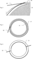
- the figure 1A is a simplified sketch and represents an assembly of two tubes 11, 12, maintained together by nuts and bolts 30.
- the tubes 11, 12 are typically used to convey fluids, such as liquids, water, oil... and tightness at the tube joint is provided by a gasket G.
- Nuts and bolts 30 provide a seating stress which compresses the gasket G which in return seals the tube joint.
- the gasket G comprises a sealing portion which is in contact with the tubes 11 and 12, via a seating surface of these tubes 11 and 12.
- the sealing portion is a compressible portion 21, also shown in figure 1B , and in this example, is made of a strip wound in spiral.
- This strip comprises a steel band 24, and a filler 25, typically made of graphite, polytetrafluoroethylene (ptfe) or mica.
- the strip and in particular the metallic band have a portion in V-shape or U-shape. It has to be noted that a W-shape is possible and can be considered as two portions in V-shape.
- the gasket G comprises an outer ring 23, which is made of steel, or stainless steel.
- the sealing portion comprises two opposite faces 21A and 21B, each being in contact with one of the respective extremity of tubes 11 and 12, to seal the tube assembly.
- the gasket G is sandwiched between the two tubes 11 and 12 via its opposite faces 21a, 21B.
- the invention provides a gasket G with seating stress measurement capacity.
- an optical fiber 22 is implemented in the outer part of the compressible portion 21.
- the optical fiber 22 comprises a sensing portion which is enclosed into the compressible portion 21, and which comprises fiber Bragg grating sensors.
- Such sensor is sensitive to strain, and when connected to a monitoring unit M as shown on figure 7 (this figure 7 does not show the nuts and bolts 30 for clarity), the optical fiber 22 provides the capacity to measure the seating stress ( ⁇ ) applied to the compressible portion 21 of the gasket G along time (t). if the seating stress becomes too low, it is possible to send an alarm to an operator for inspection and possibly adjusting the seating stress by screwing or exchanging the nuts and bolts 30, so as to avoid the risk of leak, in advance. Also the sensor will detect the temperature and if any medium (gas/liquid) will diffuse through the gasket, a second kind of alarm might be generated, based on temperature changes.
- Figure 2 shows a detail of the outer ring 23, comprising a hole 23A to guide and give access to the optical fiber 22 to the compressible portion 21 from exterior
- figure 3 shows the optical fiber 22 output from the compressible portion 21, made of the V shape metallic strip, wound with a soft filler, graphite.
- the optical fiber 22 is added to the spiral wound gasket during production of the spiral. Before the last winding with graphite will be produced; the optical fiber 22 will be added and wound with the filler 25 and metal spiral 24. When adding the optical fiber 22, it will be placed in the V-shape of the metal band 24. The optical fiber 22 will be added 'above' the filler 25. The filler 25 will be cut off after minimum one circular winding. The optical fiber 22 will be wound together with the metal windings till the outer diameter has been reached. In this part of the gasket, the optical fiber may be protected with a tube, in particular a plastic tube, and preferably a tube made of polytetrafluoroethylene (PTFE). There might have three minimum 'extra' windings of the metallic band 24. It can also be limited to a much shorter section (1/4 of a winding or even less). The sensing portion of optical fiber 22 has to be placed in the part with the filler 25.
- PTFE polytetrafluoroethylene
- the fiber will be guided to the 'outside' of the flange.
- an outer ring 23 (or guide ring) is used for the spiral wound gasket, the optical fiber 22 is guided to the outside of the guide ring 23 by a groove in the ring or a hole 23A will be drilled in the guide ring 23.
- Figure 4 and 5 represent alternative constructions of gaskets (not claimed), using homogeneous materials for the compressible portion 21.
- the optical fiber 22 is guided out of the compressible portion 21 in a tangential direction, but as shown figure 5 , radial direction guiding is also an alternative.
- Figure 2 shows a hole 23A, but it is also possible to implement a groove in the outer ring 23 to guide the optical fiber 22.
- Figures 6A represents a first possible design for the tube assembly, where tubes 11 and 12 have same flange design, and gasket G comprises an outer ring and an inner ring, the compressible portion of the gasket G being in contact with the tubes 11 and 12.
- Figure 6B represents a second possible design for the tube assembly, where tubes 11 and 12 have different flange design, and gasket G comprises only a compressible portion, with no outer or inner ring.
- one of the tube flange might be adapted to allow a passage for the optical fiber 22, with an opening such as a groove or a hole.
- Figure 6C represents a third possible design for the tube assembly, where tubes 11 and 12 have different flange design, and gasket G comprises only a compressible portion, and an inner ring.
- one of the tube flange might also be adapted to allow a passage for the optical fiber 22, with an opening such as a groove or a hole.
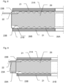
- Figure 8 represents another alternative gasket (not claimed), comprising a serrated core 26 sandwiched between two washers of compressible portions 21.
- the core 26 might be metallic (stainless steel), and the compressible portions 21 might be of graphite or polytetrafluoroethylene (PTFE), or mica, or rubber.
- the core 26 presents a serrated or corrugated or wavy interface with the compressible portions 21, the wavy interface being provided by successive grooves 26A, 26B. Alternatively, the wavy interface might be provided by a spiral groove.
- Sealing between the tubes is provided by deformation of the compressible portions 21, which can penetrate the grooves 26A, 26B, when the tubes are clamped together.
- An optical fiber 22 is provided in the groove 26B forming a receiving recess, so that the top compressible portion 21 will apply a residual pressure onto the optical fiber, which can be detected as explained above for figure 7 .
- the groove 26B (or the part of the spiral groove receiving the optical fibre) might be deeper than the rest of grooves 26A forming sealing recesses, to avoid overstress of the optical fiber 22.
- groove 26B might present a depth equal to or smaller than the depth of groove 26A added to the size (diameter) of the optical fiber 22.
- grooves 23B are provided on core 26 to allow guiding of the optical fiber 22 out of the gasket, towards a space between opposite faces 21A, 21B, so that the tube flanges do not need to be modified for optical fiber 22 presence. It should be noticed that two grooves 23B are provided on each side of core 26, so that the gasket can be equipped with two optical fibers 22 if necessary.
- Figure 9 shows an alternative gasket of figure 8 (not claimed), comprising a core 26 sandwiched between two washers of compressible portions 21, and equipped with an outer ring 23. Compared to the gasket of figure 8 , only the optional outer ring 23 will be described in detail.
- the outer ring 23 might be metallic (stainless steel for example), and comprises two holes 23A to provide guiding of the optical fiber 22.
- the holes 23A are aligned with the grooves 23B of the core 26 to provide adequate guiding of the optical fiber 22.
- the outer ring 23 might be attached to the core 26 as shown on figure 9 (internal diameter of outer ring 23 fits to outer diameter of core 26), but the outer ring 23 might be installed into a peripheral groove of the core 26.
- the opposite faces 21a and 21B might be flat or corrugated, and a typical design is to coat the opposite surfaces 21A, 21B with polytetrafluoroethylene, graphite or MICA for example.
Landscapes
- Engineering & Computer Science (AREA)
- General Engineering & Computer Science (AREA)
- Mechanical Engineering (AREA)
- Gasket Seals (AREA)
- Light Guides In General And Applications Therefor (AREA)
Claims (11)
- Dichtung (G) zum Abdichten einer Anordnung von zwei Rohren (11, 12), von denen jedes einen Endpunkt mit einer Sitzfläche umfasst,wobei die Dichtung (G) einen Dichtungsabschnitt mit zwei gegenüberliegenden Seiten (21A, 21B) umfasst, von denen jede angeordnet ist, eine jeweilige Sitzfläche zu berühren,wobei der Dichtungsabschnitt mindestens einen komprimierbaren Abschnitt (21) umfasst,wobei die Dichtung (G) eine optische Faser (22) umfasst, die einen Erfassungsabschnitt umfasst, der komprimierbare Abschnitt (21) mindestens teilweise umschlossenen und angeordnet ist, eine Komprimierungskraft zu detektieren, die von der Rohranordnung via die gegenüberliegenden Flächen (21A, 21B) auf den komprimierbaren Abschnitt (21) ausgeübt wird, wobei der komprimierbare Abschnitt (21) einen spiralförmig gewickelten Streifen umfasst,dadurch gekennzeichnet, dass die Dichtung Führungsmittel umfasst, die angeordnet sind, eine Führung der optischen Faser (22) aus dem Dichtungsabschnitt heraus bereitzustellen, wobei der Erfassungsabschnitt mindestens teilweise mit dem Streifen gewickelt ist.
- Dichtung (G) nach dem vorhergehenden Anspruch, wobei die Führungsmittel angeordnet sind, eine Führung der optischen Faser (22) zu einem Raum bereitzustellen, der zwischen zwei Ebenen angeordnet ist, die durch die zwei gegenüberliegenden Seiten (21A, 21B) definiert sind.
- Dichtung (G) nach Anspruch 1 oder 2, wobei ein Querschnitt des Streifens einen Abschnitt in V-Form oder in U-Form umfasst.
- Dichtung (G) nach dem vorhergehenden Anspruch, wobei sich der Erfassungsabschnitt der optischen Faser (22) in einem zentralen Teil der V-Form befindet.
- Dichtung (G) nach einem der Ansprüche 1 bis 4, wobei der Streifen eine Metallschicht und eine Füllschicht umfasst, wobei die Füllschicht ein Material umfasst, wie etwa Graphit, Polytetrafluorethylen oder Glimmer oder Gummi.
- Dichtung (G) nach dem vorhergehenden Anspruch, wobei sich der Erfassungsabschnitt der optischen Faser (22) mindestens teilweise in der Füllschicht befindet.
- Dichtung (G) nach einem der vorhergehenden Ansprüche, wobei der komprimierbare Abschnitt (21) einen festen Abschnitt umfasst, der aus einem homogenen Material besteht, das den Erfassungsabschnitt der optischen Faser (22) mindestens teilweise umschließt.
- Dichtung (G) nach einem der vorhergehenden Ansprüche, wobei der komprimierbare Abschnitt (21) einen Verbundabschnitt umfasst, der mindestens ein Fasermaterial umfasst und den Erfassungsabschnitt der optischen Faser (22) mindestens teilweise umschließt.
- Dichtung (G) nach einem der vorhergehenden Ansprüche, wobei der Erfassungsabschnitt der optischen Faser (22) einen Bragg-Fasergittersensor umfasst.
- Rohranordnung, die Folgendes umfasst:- mindestens zwei Rohren (11, 12), von denen jedes einen Endpunkt mit einer Sitzfläche umfasst, oder ein Rohr und eine Platte,- eine Dichtung (G) nach einem der vorhergehenden Ansprüche, die zwischen den Sitzflächen angeordnet ist,- Klemmmittel, wie etwa Bolzen, die eine Klemmkraft erzeugen, die die zwei Rohre (11, 12) montiert und die Komprimierungskraft auf den komprimierbaren Abschnitt (21) ausgeübt halten.
- Überwachungssystem, das Folgendes umfasst:- eine Rohranordnung nach dem vorhergehenden Anspruch,- eine Überwachungseinheit (M), die mit der optischen Faser (22) der Dichtung (G) verbunden ist, zum Überwachen der von der Rohranordnung auf den komprimierbaren Abschnitt (21) ausgeübten Komprimierungskraft.
Applications Claiming Priority (2)
| Application Number | Priority Date | Filing Date | Title |
|---|---|---|---|
| NL1043013A NL1043013B1 (en) | 2018-09-26 | 2018-09-26 | Gasket with long term sealing capacity |
| PCT/EP2019/075867 WO2020064837A1 (en) | 2018-09-26 | 2019-09-25 | Gasket with long term sealing capacity |
Publications (2)
| Publication Number | Publication Date |
|---|---|
| EP3857100A1 EP3857100A1 (de) | 2021-08-04 |
| EP3857100B1 true EP3857100B1 (de) | 2025-04-02 |
Family
ID=68104599
Family Applications (1)
| Application Number | Title | Priority Date | Filing Date |
|---|---|---|---|
| EP19779812.7A Active EP3857100B1 (de) | 2018-09-26 | 2019-09-25 | Dichtung mit langzeitdichtungskapazität |
Country Status (3)
| Country | Link |
|---|---|
| EP (1) | EP3857100B1 (de) |
| NL (1) | NL1043013B1 (de) |
| WO (1) | WO2020064837A1 (de) |
Families Citing this family (4)
| Publication number | Priority date | Publication date | Assignee | Title |
|---|---|---|---|---|
| US20210208018A1 (en) * | 2019-12-04 | 2021-07-08 | Lgc Us Asset Holdings, Llc | Sensor-embedded gasket for real-time monitoring |
| CN115111368A (zh) * | 2022-05-13 | 2022-09-27 | 中国航空工业集团公司北京长城计量测试技术研究所 | 一种智能石墨密封装置 |
| JP2024009660A (ja) * | 2022-07-11 | 2024-01-23 | 日本ピラー工業株式会社 | 渦巻形ガスケット及び配管継手構造 |
| CN117790955B (zh) * | 2023-12-30 | 2024-07-26 | 华中科技大学 | 一种基于光纤传感的电池故障诊断系统及方法 |
Citations (5)
| Publication number | Priority date | Publication date | Assignee | Title |
|---|---|---|---|---|
| EP2801739A2 (de) * | 2013-05-10 | 2014-11-12 | FOCE Technology International B.V. | Dichtungsdrucksensor |
| CN104806761A (zh) * | 2015-03-16 | 2015-07-29 | 武汉理工大学 | 一种基于光纤光栅传感的智能型法兰垫片 |
| GB2536962A (en) * | 2015-04-02 | 2016-10-05 | Univ Of Huddersfield | Apparatus and method for joint monitoring |
| CN106352084A (zh) * | 2016-08-31 | 2017-01-25 | 苏州宝骅机械技术有限公司 | 密封状态可监测的密封组件 |
| US20180058616A1 (en) * | 2016-08-25 | 2018-03-01 | Marc Rowley | Non-metallic high pressure high temperature high chemical compatibility flange isolation gasket |
Family Cites Families (1)
| Publication number | Priority date | Publication date | Assignee | Title |
|---|---|---|---|---|
| KR101718945B1 (ko) | 2015-03-13 | 2017-03-23 | 이종철 | 개스킷 및 이의 제작 방법 |
-
2018
- 2018-09-26 NL NL1043013A patent/NL1043013B1/en active
-
2019
- 2019-09-25 WO PCT/EP2019/075867 patent/WO2020064837A1/en not_active Ceased
- 2019-09-25 EP EP19779812.7A patent/EP3857100B1/de active Active
Patent Citations (5)
| Publication number | Priority date | Publication date | Assignee | Title |
|---|---|---|---|---|
| EP2801739A2 (de) * | 2013-05-10 | 2014-11-12 | FOCE Technology International B.V. | Dichtungsdrucksensor |
| CN104806761A (zh) * | 2015-03-16 | 2015-07-29 | 武汉理工大学 | 一种基于光纤光栅传感的智能型法兰垫片 |
| GB2536962A (en) * | 2015-04-02 | 2016-10-05 | Univ Of Huddersfield | Apparatus and method for joint monitoring |
| US20180058616A1 (en) * | 2016-08-25 | 2018-03-01 | Marc Rowley | Non-metallic high pressure high temperature high chemical compatibility flange isolation gasket |
| CN106352084A (zh) * | 2016-08-31 | 2017-01-25 | 苏州宝骅机械技术有限公司 | 密封状态可监测的密封组件 |
Also Published As
| Publication number | Publication date |
|---|---|
| EP3857100A1 (de) | 2021-08-04 |
| NL1043013B1 (en) | 2020-05-29 |
| WO2020064837A1 (en) | 2020-04-02 |
Similar Documents
| Publication | Publication Date | Title |
|---|---|---|
| EP3857100B1 (de) | Dichtung mit langzeitdichtungskapazität | |
| EP1373853B1 (de) | Anordnung an einer rohrflanschdichtung | |
| CA3000620C (en) | Monitoring probe | |
| US9939341B2 (en) | Pipeline apparatus and method | |
| EP2329106B1 (de) | Verfahren, vorrichtung und system zur erkennung von wasser oder flüssigkeit im ring eines flexiblen steigrohrs oder einer flussleitung | |
| WO2009136811A1 (en) | Sealing gasket with protection device | |
| US7447390B2 (en) | Pressure transducer with optical waveguide feedthrough assembly | |
| CN119309741A (zh) | 一种适用直埋和挂网安装的分布式油品泄漏监测光缆结构 | |
| US10495238B2 (en) | Fluid sealing device and power cable line | |
| RU2702456C1 (ru) | Интеллектуальное уплотнение для контроля состояния разъемных соединений | |
| CA2548829C (en) | Pressure transducer with optical waveguide feedthrough assembly | |
| WO2022139587A1 (en) | Insulation test gasket | |
| JP5887656B2 (ja) | 一体型フィードスルーを備えた光変換器 | |
| US11221264B2 (en) | Optical fiber sensing device for sensing the distribution of the compression or deformation of a compressible or deformable element | |
| WO2012090171A2 (en) | Flange seal | |
| KR200453018Y1 (ko) | 누설방지용 보호관 | |
| RU2014542C1 (ru) | Штуцерно-торцевое соединение трубопроводов | |
| Veiga et al. | Spiral Wound Versus Flexible Graphite Faced Serrated Metal Pipe Flange Gaskets in Thermal Cycling and Pressure Comparative Testing | |
| SU796590A1 (ru) | Уплотнение трубопровода | |
| AU736059B2 (en) | Joints | |
| WO2020139122A1 (ru) | Уплотнение между неподвижными относительно друг друга поверхностями | |
| WO2013105866A1 (en) | Access fitting for attaching a device within a process pipeline or vessel |
Legal Events
| Date | Code | Title | Description |
|---|---|---|---|
| STAA | Information on the status of an ep patent application or granted ep patent |
Free format text: STATUS: UNKNOWN |
|
| STAA | Information on the status of an ep patent application or granted ep patent |
Free format text: STATUS: THE INTERNATIONAL PUBLICATION HAS BEEN MADE |
|
| PUAI | Public reference made under article 153(3) epc to a published international application that has entered the european phase |
Free format text: ORIGINAL CODE: 0009012 |
|
| STAA | Information on the status of an ep patent application or granted ep patent |
Free format text: STATUS: REQUEST FOR EXAMINATION WAS MADE |
|
| 17P | Request for examination filed |
Effective date: 20210426 |
|
| AK | Designated contracting states |
Kind code of ref document: A1 Designated state(s): AL AT BE BG CH CY CZ DE DK EE ES FI FR GB GR HR HU IE IS IT LI LT LU LV MC MK MT NL NO PL PT RO RS SE SI SK SM TR |
|
| DAV | Request for validation of the european patent (deleted) | ||
| DAX | Request for extension of the european patent (deleted) | ||
| RAP1 | Party data changed (applicant data changed or rights of an application transferred) |
Owner name: ERIKS NV |
|
| STAA | Information on the status of an ep patent application or granted ep patent |
Free format text: STATUS: EXAMINATION IS IN PROGRESS |
|
| 17Q | First examination report despatched |
Effective date: 20230906 |
|
| REG | Reference to a national code |
Ref country code: DE Ref legal event code: R079 Free format text: PREVIOUS MAIN CLASS: F16J0015060000 Ipc: F16L0023020000 Ref document number: 602019068139 Country of ref document: DE |
|
| GRAP | Despatch of communication of intention to grant a patent |
Free format text: ORIGINAL CODE: EPIDOSNIGR1 |
|
| STAA | Information on the status of an ep patent application or granted ep patent |
Free format text: STATUS: GRANT OF PATENT IS INTENDED |
|
| RIC1 | Information provided on ipc code assigned before grant |
Ipc: F16J 15/12 20060101ALI20241008BHEP Ipc: F16J 15/10 20060101ALI20241008BHEP Ipc: F16J 15/06 20060101ALI20241008BHEP Ipc: F16L 23/18 20060101ALI20241008BHEP Ipc: F16L 23/02 20060101AFI20241008BHEP |
|
| INTG | Intention to grant announced |
Effective date: 20241028 |
|
| GRAS | Grant fee paid |
Free format text: ORIGINAL CODE: EPIDOSNIGR3 |
|
| GRAA | (expected) grant |
Free format text: ORIGINAL CODE: 0009210 |
|
| STAA | Information on the status of an ep patent application or granted ep patent |
Free format text: STATUS: THE PATENT HAS BEEN GRANTED |
|
| AK | Designated contracting states |
Kind code of ref document: B1 Designated state(s): AL AT BE BG CH CY CZ DE DK EE ES FI FR GB GR HR HU IE IS IT LI LT LU LV MC MK MT NL NO PL PT RO RS SE SI SK SM TR |
|
| REG | Reference to a national code |
Ref country code: GB Ref legal event code: FG4D |
|
| REG | Reference to a national code |
Ref country code: CH Ref legal event code: EP |
|
| REG | Reference to a national code |
Ref country code: IE Ref legal event code: FG4D |
|
| REG | Reference to a national code |
Ref country code: DE Ref legal event code: R096 Ref document number: 602019068139 Country of ref document: DE |
|
| REG | Reference to a national code |
Ref country code: NL Ref legal event code: MP Effective date: 20250402 |
|
| PG25 | Lapsed in a contracting state [announced via postgrant information from national office to epo] |
Ref country code: NL Free format text: LAPSE BECAUSE OF FAILURE TO SUBMIT A TRANSLATION OF THE DESCRIPTION OR TO PAY THE FEE WITHIN THE PRESCRIBED TIME-LIMIT Effective date: 20250402 |
|
| REG | Reference to a national code |
Ref country code: AT Ref legal event code: MK05 Ref document number: 1781557 Country of ref document: AT Kind code of ref document: T Effective date: 20250402 |
|
| PG25 | Lapsed in a contracting state [announced via postgrant information from national office to epo] |
Ref country code: PT Free format text: LAPSE BECAUSE OF FAILURE TO SUBMIT A TRANSLATION OF THE DESCRIPTION OR TO PAY THE FEE WITHIN THE PRESCRIBED TIME-LIMIT Effective date: 20250804 Ref country code: ES Free format text: LAPSE BECAUSE OF FAILURE TO SUBMIT A TRANSLATION OF THE DESCRIPTION OR TO PAY THE FEE WITHIN THE PRESCRIBED TIME-LIMIT Effective date: 20250402 Ref country code: FI Free format text: LAPSE BECAUSE OF FAILURE TO SUBMIT A TRANSLATION OF THE DESCRIPTION OR TO PAY THE FEE WITHIN THE PRESCRIBED TIME-LIMIT Effective date: 20250402 |
|
| REG | Reference to a national code |
Ref country code: LT Ref legal event code: MG9D |
|
| PG25 | Lapsed in a contracting state [announced via postgrant information from national office to epo] |
Ref country code: NO Free format text: LAPSE BECAUSE OF FAILURE TO SUBMIT A TRANSLATION OF THE DESCRIPTION OR TO PAY THE FEE WITHIN THE PRESCRIBED TIME-LIMIT Effective date: 20250702 Ref country code: GR Free format text: LAPSE BECAUSE OF FAILURE TO SUBMIT A TRANSLATION OF THE DESCRIPTION OR TO PAY THE FEE WITHIN THE PRESCRIBED TIME-LIMIT Effective date: 20250703 |
|
| PG25 | Lapsed in a contracting state [announced via postgrant information from national office to epo] |
Ref country code: PL Free format text: LAPSE BECAUSE OF FAILURE TO SUBMIT A TRANSLATION OF THE DESCRIPTION OR TO PAY THE FEE WITHIN THE PRESCRIBED TIME-LIMIT Effective date: 20250402 |
|
| PG25 | Lapsed in a contracting state [announced via postgrant information from national office to epo] |
Ref country code: BG Free format text: LAPSE BECAUSE OF FAILURE TO SUBMIT A TRANSLATION OF THE DESCRIPTION OR TO PAY THE FEE WITHIN THE PRESCRIBED TIME-LIMIT Effective date: 20250402 |
|
| PGFP | Annual fee paid to national office [announced via postgrant information from national office to epo] |
Ref country code: BE Payment date: 20250929 Year of fee payment: 7 |
|
| PG25 | Lapsed in a contracting state [announced via postgrant information from national office to epo] |
Ref country code: HR Free format text: LAPSE BECAUSE OF FAILURE TO SUBMIT A TRANSLATION OF THE DESCRIPTION OR TO PAY THE FEE WITHIN THE PRESCRIBED TIME-LIMIT Effective date: 20250402 |
|
| PG25 | Lapsed in a contracting state [announced via postgrant information from national office to epo] |
Ref country code: AT Free format text: LAPSE BECAUSE OF FAILURE TO SUBMIT A TRANSLATION OF THE DESCRIPTION OR TO PAY THE FEE WITHIN THE PRESCRIBED TIME-LIMIT Effective date: 20250402 |
|
| PGFP | Annual fee paid to national office [announced via postgrant information from national office to epo] |
Ref country code: FR Payment date: 20250929 Year of fee payment: 7 |
|
| PG25 | Lapsed in a contracting state [announced via postgrant information from national office to epo] |
Ref country code: RS Free format text: LAPSE BECAUSE OF FAILURE TO SUBMIT A TRANSLATION OF THE DESCRIPTION OR TO PAY THE FEE WITHIN THE PRESCRIBED TIME-LIMIT Effective date: 20250702 |
|
| PGFP | Annual fee paid to national office [announced via postgrant information from national office to epo] |
Ref country code: IE Payment date: 20250929 Year of fee payment: 7 |
|
| PG25 | Lapsed in a contracting state [announced via postgrant information from national office to epo] |
Ref country code: IS Free format text: LAPSE BECAUSE OF FAILURE TO SUBMIT A TRANSLATION OF THE DESCRIPTION OR TO PAY THE FEE WITHIN THE PRESCRIBED TIME-LIMIT Effective date: 20250802 |
|
| PG25 | Lapsed in a contracting state [announced via postgrant information from national office to epo] |
Ref country code: LV Free format text: LAPSE BECAUSE OF FAILURE TO SUBMIT A TRANSLATION OF THE DESCRIPTION OR TO PAY THE FEE WITHIN THE PRESCRIBED TIME-LIMIT Effective date: 20250402 |
|
| REG | Reference to a national code |
Ref country code: DE Ref legal event code: R097 Ref document number: 602019068139 Country of ref document: DE |
|
| PGFP | Annual fee paid to national office [announced via postgrant information from national office to epo] |
Ref country code: DE Payment date: 20251020 Year of fee payment: 7 |
|
| PGFP | Annual fee paid to national office [announced via postgrant information from national office to epo] |
Ref country code: GB Payment date: 20251024 Year of fee payment: 7 |
|
| PG25 | Lapsed in a contracting state [announced via postgrant information from national office to epo] |
Ref country code: DK Free format text: LAPSE BECAUSE OF FAILURE TO SUBMIT A TRANSLATION OF THE DESCRIPTION OR TO PAY THE FEE WITHIN THE PRESCRIBED TIME-LIMIT Effective date: 20250402 Ref country code: SM Free format text: LAPSE BECAUSE OF FAILURE TO SUBMIT A TRANSLATION OF THE DESCRIPTION OR TO PAY THE FEE WITHIN THE PRESCRIBED TIME-LIMIT Effective date: 20250402 |
|
| PG25 | Lapsed in a contracting state [announced via postgrant information from national office to epo] |
Ref country code: CZ Free format text: LAPSE BECAUSE OF FAILURE TO SUBMIT A TRANSLATION OF THE DESCRIPTION OR TO PAY THE FEE WITHIN THE PRESCRIBED TIME-LIMIT Effective date: 20250402 |
|
| PG25 | Lapsed in a contracting state [announced via postgrant information from national office to epo] |
Ref country code: EE Free format text: LAPSE BECAUSE OF FAILURE TO SUBMIT A TRANSLATION OF THE DESCRIPTION OR TO PAY THE FEE WITHIN THE PRESCRIBED TIME-LIMIT Effective date: 20250402 |
|
| PG25 | Lapsed in a contracting state [announced via postgrant information from national office to epo] |
Ref country code: SK Free format text: LAPSE BECAUSE OF FAILURE TO SUBMIT A TRANSLATION OF THE DESCRIPTION OR TO PAY THE FEE WITHIN THE PRESCRIBED TIME-LIMIT Effective date: 20250402 Ref country code: RO Free format text: LAPSE BECAUSE OF FAILURE TO SUBMIT A TRANSLATION OF THE DESCRIPTION OR TO PAY THE FEE WITHIN THE PRESCRIBED TIME-LIMIT Effective date: 20250402 |
|
| PG25 | Lapsed in a contracting state [announced via postgrant information from national office to epo] |
Ref country code: IT Free format text: LAPSE BECAUSE OF FAILURE TO SUBMIT A TRANSLATION OF THE DESCRIPTION OR TO PAY THE FEE WITHIN THE PRESCRIBED TIME-LIMIT Effective date: 20250402 |
|
| PLBE | No opposition filed within time limit |
Free format text: ORIGINAL CODE: 0009261 |
|
| STAA | Information on the status of an ep patent application or granted ep patent |
Free format text: STATUS: NO OPPOSITION FILED WITHIN TIME LIMIT |
|
| REG | Reference to a national code |
Ref country code: CH Ref legal event code: L10 Free format text: ST27 STATUS EVENT CODE: U-0-0-L10-L00 (AS PROVIDED BY THE NATIONAL OFFICE) Effective date: 20260211 |
|
| 26N | No opposition filed |
Effective date: 20260105 |