EP3857183B1 - Système et procédé de détermination d'une distribution de niveau et de densité - Google Patents
Système et procédé de détermination d'une distribution de niveau et de densité Download PDFInfo
- Publication number
- EP3857183B1 EP3857183B1 EP19769782.4A EP19769782A EP3857183B1 EP 3857183 B1 EP3857183 B1 EP 3857183B1 EP 19769782 A EP19769782 A EP 19769782A EP 3857183 B1 EP3857183 B1 EP 3857183B1
- Authority
- EP
- European Patent Office
- Prior art keywords
- signal
- reflection
- phase product
- transmit signal
- liquid phase
- Prior art date
- Legal status (The legal status is an assumption and is not a legal conclusion. Google has not performed a legal analysis and makes no representation as to the accuracy of the status listed.)
- Active
Links
Images


Classifications
-
- G—PHYSICS
- G01—MEASURING; TESTING
- G01F—MEASURING VOLUME, VOLUME FLOW, MASS FLOW OR LIQUID LEVEL; METERING BY VOLUME
- G01F23/00—Indicating or measuring liquid level or level of fluent solid material, e.g. indicating in terms of volume or indicating by means of an alarm
- G01F23/22—Indicating or measuring liquid level or level of fluent solid material, e.g. indicating in terms of volume or indicating by means of an alarm by measuring physical variables, other than linear dimensions, pressure or weight, dependent on the level to be measured, e.g. by difference of heat transfer of steam or water
- G01F23/28—Indicating or measuring liquid level or level of fluent solid material, e.g. indicating in terms of volume or indicating by means of an alarm by measuring physical variables, other than linear dimensions, pressure or weight, dependent on the level to be measured, e.g. by difference of heat transfer of steam or water by measuring the variations of parameters of electromagnetic or acoustic waves applied directly to the liquid or fluent solid material
- G01F23/284—Electromagnetic waves
-
- G—PHYSICS
- G01—MEASURING; TESTING
- G01F—MEASURING VOLUME, VOLUME FLOW, MASS FLOW OR LIQUID LEVEL; METERING BY VOLUME
- G01F23/00—Indicating or measuring liquid level or level of fluent solid material, e.g. indicating in terms of volume or indicating by means of an alarm
- G01F23/80—Arrangements for signal processing
- G01F23/802—Particular electronic circuits for digital processing equipment
- G01F23/804—Particular electronic circuits for digital processing equipment containing circuits handling parameters other than liquid level
-
- G—PHYSICS
- G01—MEASURING; TESTING
- G01N—INVESTIGATING OR ANALYSING MATERIALS BY DETERMINING THEIR CHEMICAL OR PHYSICAL PROPERTIES
- G01N9/00—Investigating density or specific gravity of materials; Analysing materials by determining density or specific gravity
- G01N9/24—Investigating density or specific gravity of materials; Analysing materials by determining density or specific gravity by observing the transmission of wave or particle radiation through the material
-
- G—PHYSICS
- G01—MEASURING; TESTING
- G01S—RADIO DIRECTION-FINDING; RADIO NAVIGATION; DETERMINING DISTANCE OR VELOCITY BY USE OF RADIO WAVES; LOCATING OR PRESENCE-DETECTING BY USE OF THE REFLECTION OR RERADIATION OF RADIO WAVES; ANALOGOUS ARRANGEMENTS USING OTHER WAVES
- G01S13/00—Systems using the reflection or reradiation of radio waves, e.g. radar systems; Analogous systems using reflection or reradiation of waves whose nature or wavelength is irrelevant or unspecified
- G01S13/02—Systems using reflection of radio waves, e.g. primary radar systems; Analogous systems
- G01S13/06—Systems determining position data of a target
- G01S13/08—Systems for measuring distance only
- G01S13/32—Systems for measuring distance only using transmission of continuous waves, whether amplitude-, frequency-, or phase-modulated, or unmodulated
- G01S13/34—Systems for measuring distance only using transmission of continuous waves, whether amplitude-, frequency-, or phase-modulated, or unmodulated using transmission of continuous, frequency-modulated waves while heterodyning the received signal, or a signal derived therefrom, with a locally-generated signal related to the contemporaneously transmitted signal
- G01S13/343—Systems for measuring distance only using transmission of continuous waves, whether amplitude-, frequency-, or phase-modulated, or unmodulated using transmission of continuous, frequency-modulated waves while heterodyning the received signal, or a signal derived therefrom, with a locally-generated signal related to the contemporaneously transmitted signal using sawtooth modulation
-
- G—PHYSICS
- G01—MEASURING; TESTING
- G01S—RADIO DIRECTION-FINDING; RADIO NAVIGATION; DETERMINING DISTANCE OR VELOCITY BY USE OF RADIO WAVES; LOCATING OR PRESENCE-DETECTING BY USE OF THE REFLECTION OR RERADIATION OF RADIO WAVES; ANALOGOUS ARRANGEMENTS USING OTHER WAVES
- G01S13/00—Systems using the reflection or reradiation of radio waves, e.g. radar systems; Analogous systems using reflection or reradiation of waves whose nature or wavelength is irrelevant or unspecified
- G01S13/88—Radar or analogous systems specially adapted for specific applications
-
- G—PHYSICS
- G01—MEASURING; TESTING
- G01S—RADIO DIRECTION-FINDING; RADIO NAVIGATION; DETERMINING DISTANCE OR VELOCITY BY USE OF RADIO WAVES; LOCATING OR PRESENCE-DETECTING BY USE OF THE REFLECTION OR RERADIATION OF RADIO WAVES; ANALOGOUS ARRANGEMENTS USING OTHER WAVES
- G01S7/00—Details of systems according to groups G01S13/00, G01S15/00, G01S17/00
- G01S7/02—Details of systems according to groups G01S13/00, G01S15/00, G01S17/00 of systems according to group G01S13/00
- G01S7/024—Details of systems according to groups G01S13/00, G01S15/00, G01S17/00 of systems according to group G01S13/00 using polarisation effects
- G01S7/025—Details of systems according to groups G01S13/00, G01S15/00, G01S17/00 of systems according to group G01S13/00 using polarisation effects involving the transmission of linearly polarised waves
-
- G—PHYSICS
- G01—MEASURING; TESTING
- G01S—RADIO DIRECTION-FINDING; RADIO NAVIGATION; DETERMINING DISTANCE OR VELOCITY BY USE OF RADIO WAVES; LOCATING OR PRESENCE-DETECTING BY USE OF THE REFLECTION OR RERADIATION OF RADIO WAVES; ANALOGOUS ARRANGEMENTS USING OTHER WAVES
- G01S7/00—Details of systems according to groups G01S13/00, G01S15/00, G01S17/00
- G01S7/02—Details of systems according to groups G01S13/00, G01S15/00, G01S17/00 of systems according to group G01S13/00
- G01S7/41—Details of systems according to groups G01S13/00, G01S15/00, G01S17/00 of systems according to group G01S13/00 using analysis of echo signal for target characterisation; Target signature; Target cross-section
- G01S7/411—Identification of targets based on measurements of radar reflectivity
Definitions
- the present invention relates to a radar level gauge system and to a method of determining a level of an interface between liquid phase product and vapor phase product in a tank, and a density distribution in the liquid phase product.
- Radar level gauge (RLG) systems are in wide use for determining the filling levels of products in tanks. Radar level gauging is generally performed either by means of non-contact measurement, whereby electromagnetic signals are radiated towards the product contained in the tank, or by means of contact measurement, often referred to as guided wave radar (GWR), whereby electromagnetic signals are guided towards and into the product by a probe acting as a waveguide.
- GWR guided wave radar
- the probe is generally arranged to extend vertically from the top towards the bottom of the tank.
- An electromagnetic transmit signal is generated by a transceiver and propagated towards the surface of the product in the tank, and an electromagnetic reflection signal resulting from reflection of the transmit signal at the surface is propagated back towards to the transceiver.
- the distance to the surface of the product can be determined.
- non-contacting radar level gauge systems are used, together with so-called still-pipes for measuring the filling level in tanks containing Liquefied Natural Gas (LNG).
- LNG Liquefied Natural Gas
- Such tanks may be land-based, or on ships.
- the density of liquid phase product (mainly methane) may differ.
- the density at different levels in the tank may also be different. The density is therefore an important parameter, in addition to the volume for determining the quantity of product in the tank.
- Rollover refers to the rapid release of LNG vapor that can occur as a result of the spontaneous mixing of layers of different densities of LNG in a storage or cargo tank.
- a pre-condition for rollover is that stratification has occurred, i.e. the existence in the tank of two separate layers of LNG of different density.
- venting of LNG vapor should be avoided whenever possible.
- US 9 410 904 relates to a system and method for determining a density of a nonconducting medium in a tank is disclosed where the relationship between a dielectric constant and a density of the medium is known.
- the system comprises a transceiver, and a waveguide, the waveguide extends towards and into the medium.
- the system further comprises a first microwave resonator located along the waveguide.
- the first microwave resonator has a resonance frequency, which depends on a dielectric constant of a medium surrounding the resonator according to a known relationship, and is arranged to reflect a portion in the frequency domain of a signal being guided along the waveguide.
- the system further comprises processing circuitry connected to the transceiver and configured to determine the resonance frequency based on a received reflected signal, and to determine a density of the medium at the location of the first microwave resonator based on the resonance frequency.
- a general object of the present invention is to provide an improved radar level gauge system, in particular a radar level gauge system providing for improved determination of a density distribution in the liquid phase product in the tank in connection with determination of the level of the interface between liquid phase product and vapor phase product.
- Each of the "first transceiver” and the “second transceiver” may be one functional unit capable of transmitting and receiving electromagnetic signals, or may be a system comprising separate transmitter and receiver units.
- the first transceiver and the second transceiver may advantageously constitute two separate and mutually independent measurement channels, sharing the same antenna.
- the first reflection signal may practically only comprise reflections of the first transmit signal at impedance discontinuities experienced by the first transmit signal
- the second reflection signal may practically only comprise reflections of the second transmit signal at impedance discontinuities experienced by the second transmit signal.
- Each of the first transmit signal and the second transmit signal may advantageously be a microwave signal.
- each transmit signal may be frequency and/or amplitude modulated on a carrier in the microwave frequency range.
- the above-mentioned first and second sets of signal properties may include any property of the first and second transmit signals, respectively, that can be used to separate the first and second reflection signals between the first and second transceivers and that provides for the desired selective interaction with the signal interacting structures.
- Such signal properties may, for example, include propagation mode and polarization.
- suitable antennas may include a horn antenna, an array antenna, a solid dielectric antenna, and a parabolic antenna, etc.
- the tubular waveguide may be provided in the form of a so-called still pipe, which is a metal tube with circular cross section extending from the top of the tank to the bottom of the tank.
- a microwave absorber may be arranged below the lower end of the tubular waveguide to at least reduce the amplitude of a bottom reflection signal.
- the tubular waveguide may be provided with openings distributed along the length thereof, to allow liquid phase product to move between an inside and an outside of the tubular waveguide, to thereby allow the level of the interface between liquid phase product and vapor phase product to be the same on the inside of the tubular waveguide as on the outside of the tubular waveguide.
- each signal interacting structure in the first plurality of signal interacting structures is arranged and configured to selectively interact with the second transmit signal to contribute to the second reflection signal, should be understood to mean that the interaction between each interacting structure in the first plurality of signal interacting structures and the second transmit signal is considerably stronger than any interaction between each interacting structure in the first plurality of signal interacting structures and the first transmit signal.
- the signal interacting structures may advantageously be attached to the tubular waveguide.
- the density of a dielectric material can be determined based on an evaluation of the propagation of an electromagnetic signal through the material, either by a direct correlation, or indirectly through a determination of the dielectric constant, followed by a correlation between the dielectric constant and the density.
- processing circuitry may be provided as one device or several devices working together.
- the present invention is based on the realization that the level of the interface between liquid phase product and vapor phase product, and the density distribution in the liquid phase product can be determined using different transceivers/measurement channels for transmitting and receiving electromagnetic signals with different sets of signal properties, sharing the same antenna and tubular waveguide.
- the present inventors have further realized that the determination of the level of the interface can be improved by providing signal interacting structures at different levels along at the tubular mounting structures, where each signal interacting structure is arranged and configured to substantially only interact with the signals in one of the measurement channels.
- the signals interacting with the signal interacting structures can be used to determine the density distribution, and the signals exhibiting no or only relatively weak interaction with the signal interacting structures can be used to determine the level of the interface. This may facilitate a more precise determination of the level of the interface, in particular when the level of the interface is near the level of one of the signal interacting structures.
- the first plurality of signal interacting structures may comprise at least three signal interacting structures, mutually spaced apart along the first segment of said tubular waveguide.
- a measure of the density distribution in the liquid phase product may be determined based on signal interaction with two signal interacting structures that are arranged below the interface between liquid phase product and vapor phase product.
- the first set of signal properties may comprise a first polarization
- the second set of signal properties may comprise a second polarization, different from the first polarization
- the first polarization may be a first linear polarization
- the second polarization may be a second linear polarization, orthogonal to the first linear polarization
- the first set of signal properties may comprise a first propagation mode
- the second set of signal properties may comprise a second propagation mode, different from the first propagation mode.
- suitable propagation modes may include TE 11 , TM 01 , TE 21 and TE 31 .
- each signal interacting structure in the first plurality of signal interacting structures may be a reflecting structure arranged and configured to exhibit a first reflection coefficient for the first transmit signal and a second reflection coefficient for the second transmit signal, a ratio between the first reflection coefficient and the second reflection coefficient being less than 1:2.
- the first reflection coefficient may be less than half the second reflection coefficient.
- this ratio may be less than 1:3, and even more advantageously less than 1:4.
- the reflecting structures may, for example be provided in the form of pins, which may be made of metal or a dielectric material, or a composite of a conductive and a dielectric material. Such pins may have any cross-section.
- the reflecting structures may, for example, be provided in the form of one or several rings arranged inside the tubular waveguide. Examples of this type of reflecting structures are described in US 7 345 622 .
- reflecting signal interacting structures are used, and the processing circuitry is configured to determine a first measure indicative of a distance between a first signal interacting structure and a second signal interacting structure in the first plurality of signal interacting structure based on a relation between the second transmit signal and the second reflection signal; a second measure indicative of a distance between a third signal interacting structure and a fourth signal interacting structure in the first plurality of signal interacting structure based on a relation between the second transmit signal and the second reflection signal; a first average density for a first level range in the tank based on the first measure; and a second average density for a second level range in the tank based on the second measure.
- the above-mentioned second and third signal interacting structures may be the same signal interacting structure.
- the density (average density) may be determined based on a direct and previously determined correlation between density and measured electrical distance.
- the density (average density) may be determined based on a direct and previously determined correlation between dielectric constant and measured electrical distance, and on a known relation between dielectric constant and density.
- the (electrical) distance between two reflectors may be measured when the reflectors are unsubmerged in liquid phase product (for example when the tank has been emptied) and when the reflectors are submerged in liquid phase product. A relation between these measurements is sufficient to determine the change in dielectric constant, which can be used to determine the average density in the level segment between the two reflectors.
- a cross-section dimension such as diameter for a circular cross-section
- each signal interacting structure in the first plurality of signal interacting structures may be a resonator arranged and configured to be excitable only by the second transmit signal, a resonance frequency of the resonator being indicative of a density of liquid phase product filling the resonator.
- the density distribution in the liquid phase product can be determined based on an evaluation of the frequency spectrum of the second reflection signal for different levels, to identify resonance frequencies of different resonators.
- the processing circuitry may be configured to determine a first density for a first level in the tank based on a resonance frequency of a first resonator arranged at the first level; and a second density for a second level in the tank based on a resonance frequency of a second resonator arranged at the second level.
- the resonator may advantageously have a high Q-value, such as higher than 100.
- the resonator may comprise a resonator cavity arranged to contain the liquid phase product when submerged in the liquid phase product.
- the resonance frequency of a resonator cavity will depend on the dielectric constant, and thus density, of the liquid phase product filling the resonator cavity.
- dipole resonators may be used.
- the tubular waveguide comprises at least a first plurality of openings to selectively allow an electromagnetic field resulting from the second transmit signal to be present on an outside of the tubular waveguide at each opening in the first plurality of openings; and each signal interacting structure in the first plurality of signal interacting structures is arranged on the outside of the tubular waveguide at each opening in the first plurality of openings, to be excitable by the second transmit signal.
- the radar level gauge system comprises a second plurality of signal interacting structures arranged at different levels along a second segment of the tubular waveguide different from the first segment, each signal interacting structure in the second plurality of signal interacting structures being configured to selectively interact with the first transmit signal to contribute to the first reflection signal; and the processing circuitry is configured to: determine, for levels along the first segment of the tubular waveguide, the level of the interface between liquid phase product and vapor phase product based on a relation between the first transmit signal and the first reflection signal, and the density distribution in the liquid phase product based on the second reflection signal along the first segment of the tubular waveguide and based on the first reflection signal along the second segment of the tubular waveguide; and determine, for levels along the second segment of the tubular waveguide, the level of the interface between liquid phase product and vapor phase product based on a relation between the second transmit signal and the second reflection signal, and the density distribution in the liquid phase product based on the first reflection signal along the second segment of the tubular waveguide.
- a larger number of signal interacting structures may be used without excessive disturbance of the determination of the level of the interface. This allows for a more precise determination of the density distribution in the liquid phase product and/or determination of the density distribution in a larger (higher) tank.
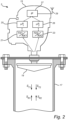
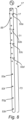
- Fig 1 schematically shows a tank monitoring arrangement 1 comprising a radar level gauge system 3 according to an example embodiment of the present invention, and a host system 5 illustrated as a control room.
- the radar level gauge system 3 is installed at a tank 7, together with additional gauges, together forming a so-called inventory tank gauging system.
- the radar level gauge system 3 is installed to measure the level of an interface 13 between liquid phase product 9 and vapor phase product 11, as well as a density distribution in the liquid phase product 9.
- the radar level gauge system 3 comprises a measuring unit 15, an antenna (not visible in fig 1 ), a tubular waveguide 17, and at least a first plurality of signal interacting structures (not visible in fig 1 ) arranged at different levels along a first segment of the tubular waveguide 17.
- the radar level gauge system 3 comprises an antenna 19, here in the form of an array antenna, arranged to radiate electromagnetic signals into the tubular waveguide 17.
- the radar level gauge system 3 comprises a first transceiver 21, a second transceiver 23, processing circuitry comprising a first measurement processor 25 and a second measurement processor 26, a communication interface 27, and a communication antenna 29.
- the first measurement processor 25 controls the first transceiver 21 to generate, transmit and receive electromagnetic signals having a first set of signal properties
- the second measurement processor 26 controls the second transceiver 23 to generate, transmit and receive electromagnetic signals having a second set of signal properties.
- the antenna 19 is coupled to the first transceiver 21 and the second transceiver 23, and configured to radiate a first transmit signal S T1 from the first transceiver 21 and to return a first reflection signal S R1 resulting from reflection of the first transmit signal, and to radiate a second transmit signal S T2 from the second transceiver 23 and to return a second reflection signal S R2 resulting from reflection of the second transmit signal.
- the first measurement processor 25 determines the level of the interface 13 based on the first transmit signal S T1 and the first reflected signal S R1
- the second measurement processor 26 determines the density distribution in the liquid phase product based on the second transmit signal S T2 and the second reflected signal S R2 .
- a measure indicative of the level of the interface 13, as well as a measure indicative the density distribution is provided to an external device, such as a control center from the first measurement processor 25 and the second measurement processor 26 via the communication interface 27 and the communication antenna 29.
- the radar level gauge system 3 may advantageously be configured according to the so-called WirelessHART communication protocol (IEC 62591).
- the level of the interface 13 may be determined based on the phase difference between a phase-modulated first transmit signal S T1 and the first reflection signal S R1 .
- the density distribution in the liquid phase product 9 may be determined based on the phase difference between a phase-modulated second transmit signal S T2 and the second reflection signal S R2 .
- This type of measurement scheme is often generally referred to as FMCW (Frequency Modulated Continuous Wave), which is, per se, well known to those of ordinary skill in the art.
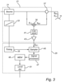
- FIG 3 there is shown a more detailed block diagram of an example configuration of a first measurement channel comprising the first transceiver 21 and the first measurement processor 25 in fig 2 . It should be understood that a second measurement channel comprising the second transceiver 23 and the second measurement processor 26 may have a generally identical configuration.
- the first transceiver 21 is here shown as including a microwave source 31 driven by a step generator 33, in turn controlled by timing circuitry 35 included in the first measurement processor 25.
- the microwave source 31 is connected to the antenna 19 via a power divider 37.
- the power divider 37 is arranged to connect a reflection signal from the antenna 19 to a mixer 39, which is also connected to receive the signal from the microwave source 31.
- the mixer output is connected to a low pass filter 41 and an amplifier 43.
- the first measurement processor 25 here includes, in addition to the timing circuitry 35 mentioned above, a sampler 45 configured to receive and sample the intermediate frequency signal S IF1 output by the mixer 39, low pass filtered by the low pass filter 41 and amplified by the amplifier 43.
- the sampler 45 may, for example, comprise a sample-and-hold circuit in combination with an A/D-converter, or be realized as a sigma-delta converter.
- the sampler 45 is controlled by the timing circuitry 35 to be synchronized with the transmit signal S T1 .
- the first measurement processor 25 further includes a signal processor 47, a memory 49, and a level determinator 51.
- first transceiver 21 and the second transceiver 23 are typically implemented in hardware, and form part of an integrated unit normally referred to as a microwave unit, at least some portions of the first measurement processor 25 and the second measurement processor 26 may typically be embodied by software modules executed by an embedded processor.
- the invention is not restricted to this particular realization, and any implementation found suitable to realize the herein described functionality may be contemplated.
- the timing circuitry 35 controls the microwave source 31 via the step generator 33 to form the transmit signal S T1 .
- the transmit signal S T1 is provided in the form of a time sequence f 0 - f N of a number of discrete and mutually different frequencies f n .
- the discrete and mutually different frequencies f 0 - f N define a bandwidth B.
- the frequencies adjacent in terms of frequency are also adjacent in the time sequence, but this is not necessarily the case.
- the discrete and mutually different frequencies may be output in an arbitrary but known order.
- the reflection signal S R1 results from reflection of the transmit signal S T1 at impedance discontinuities (including the interface 13 indicated in fig 1 ). Due to the time-of-flight from the radar level gauge system to different impedance discontinuities and back, the reflection signal S R1 will be a delayed copy of the transmit signal S T1 , where the portions of the reflection signal S R1 reflected from the different impedance discontinuities will exhibit different phase differences as compared to the transmit signal S T1 . The phase differences will, furthermore, change in steps with the changes in transmitted discrete frequency f n .
- An intermediate frequency signal S IF1 is formed by combining the transmit signal S T1 and the reflection signal S R1 in the mixer 39.
- the intermediate frequency signal S IF1 is schematically shown in fig 5 .
- the intermediate frequency signal would have been a continuous signal comprising one frequency component for each time-of-flight corresponding to the different impedance discontinuities encountered by the transmit signal.
- the phase difference will vary in steps, which means that the intermediate frequency signal S IF1 will be piece-wise constant with the same duration of the constant portions as the duration of transmission of the different frequencies f n of the transmit signal S T1 .
- This is schematically indicated in fig 5 .
- the intermediate frequency signal S IF1 which has been sampled by the sampler 45 in fig 3 is processed by the signal processor 47 in order to determine a data set indicative of echoes from impedance discontinuities.
- the intermediate frequency signal S IF1 in fig 5 is first transformed from the time domain to the frequency domain using, for example, FFT (Fast Fourier Transform). Following transformation to the frequency domain of the intermediate frequency signal S IF1 , the resulting frequency spectrum is transformed to an echo curve, which is used by the level determinator 51 to determine the level of the interface 13 between liquid phase product 9 and vapor phase product 11.
- FFT Fast Fourier Transform
- the second measurement processor 26 may comprise a density distribution determinator instead of the level determinator 51 of the first measurement channel described above.
- the first transceiver 21 In the first measurement channel, the first transceiver 21 generates, transmits and receives electromagnetic signal having a first set of signal properties, and in the second measurement channel, the second transceiver 23 generates, transmits and receives electromagnetic signal having a second set of signal properties.
- the signal properties may, for example, include polarization state and/or microwave propagation mode, etc.
- the signal interacting structures arranged at different levels along the tubular waveguide 17 are configured to selectively interact with a transmit signal, depending on the set of signal properties exhibited by the transmit signal.
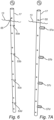
- Fig 6 schematically illustrates a first example configuration of signal interacting structures, including a first plurality of signal interacting structures, in the form of reflectors 53a-d, arranged at different levels along the tubular waveguide 17.
- the tubular waveguide 17 (often referred to as still pipe) comprises a plurality of openings 55 (only one of these is indicated with a reference numeral to avoid cluttering the drawings) to allow equalization of the level of the interface 13 on the inside and on the outside of the tubular waveguide 17.
- each reflector 53a-d is provided in the form of a pin oriented in the 'x'-direction as is schematically indicated in fig 6 .
- the pin which may be made of metal or a suitable dielectric material, will exhibit a considerably higher reflection coefficient for an electromagnetic signal with a linear polarization along the 'x'-direction, than for an electromagnetic signal with a linear polarization along the 'y'-direction.
- the first transmit signal S T1 should preferably be linearly polarized along the ⁇ y'-direction
- the second transmit signal S T2 should preferably be linearly polarized along the 'x'-direction.
- first transmit signal S T1 will propagate through the tubular waveguide with very little interaction with the reflectors 53a-d, and result in a relatively undisturbed first reflection signal S R1 having a strong reflection signal component from reflection of the first transmit signal S T1 at the interface 13 between liquid state product 9 and vapor state product 11.
- the second transmit signal S T2 will interact strongly with the reflectors 53a-d, resulting in strong reflection signal components from reflections at the reflectors 53a-d.
- a detailed description of how to provide a linearly polarized transmit signal, and how the reflectors 53a-d may suitably be configured is omitted, since this is, per se, well known to one of ordinary skill in the art of radar level gauging. For instance, US 5 136 299 may be referred to.
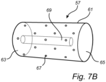
- Fig 7A schematically illustrates a second example configuration of signal interacting structures, including a first plurality of signal interacting structures, in the form of resonators 57a-d, arranged at different levels along the tubular waveguide 17.
- each resonator 57a-d is provided in the form a horizontally aligned microwave resonator attached to the outside of the tubular waveguide 17, and aligned with a corresponding opening 59a-d in the wall of the tubular resonator 17.
- An example microwave resonator configuration will be described in more detail below with reference to fig 7B .
- An electromagnetic signal with a linear polarization along the 'x'-direction will exhibit some leakage through the openings 59a-d, and the leaked signal will interact with the microwave resonators 57a-d.
- An electromagnetic signal with a linear polarization along the 'y'-direction will exhibit no or only very small leakage through the openings 59a-d, and thus be unaffected by the openings 59a-d and the microwave resonators 57a-d.
- the first transmit signal S T1 should preferably be linearly polarized along the 'y'-direction
- the second transmit signal S T2 should preferably be linearly polarized along the 'x'-direction. This means that the first transmit signal S T1 will propagate through the tubular waveguide 17 with very little interaction with the microwave resonators 57a-d, and result in a relatively undisturbed first reflection signal S R1 having a strong reflection signal component from reflection of the first transmit signal S T1 at the interface 13 between liquid state product 9 and vapor state product 11.
- the second transmit signal S T2 will interact strongly with the microwave resonators 57a-d, resulting in peaks in the second reflection signal S R2 for the respective resonance frequencies of the microwave resonators 57a-d.
- the resonance frequency of a particular microwave resonator 57a-d will depend on the dielectric constant of the liquid phase product 9 filling and/or surrounding the microwave resonator 57a-d. Based on the dielectric constants at the different levels, densities at the different levels can be determined, as is described in greater detail in US 9 410 904 .
- a horizontally aligned microwave resonator 57 comprises a housing 61 having a circular cylindrical shape.
- the housing 61 has an open end 63 and a closed end 65.
- holes 67 are provided in the housing 61. These holes 67 may advantageously be relatively small, preferably having a diameter less than 4 mm. The suitable diameter for a given application is determined by the diameter of the resonator and by the resonance frequency. The holes 67 should be sufficiently small such that they do not influence the properties of the resonator, in particular smaller than the wavelength of the resonance frequency.
- the microwave resonator 57 comprises an inner rod 69 which is fixed to the closed end 63 and extends from the closed end 63 towards the open end 65 within the housing 61.
- the functionality of the microwave resonator 57 in fig 7B , as well as other feasible microwave resonator designs are described in US 9 410 904 .
- Fig 8 schematically illustrates a third example configuration of signal interacting structures, including a first plurality of signal interacting structures and a second plurality of signal interacting structures, in the form of reflectors, arranged at different levels along a first segment 71 and a second segment 73 of the tubular waveguide 17, respectively.
- each reflector 53a-h is provided in the form of a pin.
- Each pin 53a-d in the first plurality of signal interacting structures is oriented in the 'x'-direction as is schematically indicated in fig 8 , and will thus exhibit a considerably higher reflection coefficient for an electromagnetic signal with a linear polarization along the 'x'-direction, than for an electromagnetic signal with a linear polarization along the 'y'-direction.
- Each pin 53e-h in the second plurality of signal interacting structures is oriented in the ⁇ y'-direction as is schematically indicated in fig 8 , and will thus exhibit a considerably higher reflection coefficient for an electromagnetic signal with a linear polarization along the ⁇ y'-direction, than for an electromagnetic signal with a linear polarization along the 'x'-direction.
- the first transmit signal S T1 is linearly polarized along the ⁇ y'-direction
- the second transmit signal S T2 is linearly polarized along the 'x'-direction
- the first transmit signal S T1 will practically only interact with the reflectors 53e-h in the second plurality of reflectors
- the second transmit signal S T2 will practically only interact with the reflectors 53a-d in the first plurality of reflectors.
- the first transmit signal S T1 and the first reflection signal S R1 may advantageously be used for determining the level of the interface 13 when the level of the interface 13 is in the first segment 71 of the tubular waveguide 17, as well as for determining the density distribution along the second segment 73 of the tubular waveguide 17.
- the density distribution along (the submerged portion of) the first segment 71 of the tubular waveguide 17 is determined based on the second transmit signal S T2 and the second reflection signal S R2 as described above with reference to fig 6 .
- the second transmit signal S T2 and the second reflection signal S R2 may advantageously be used for determining the level of the interface 13.
- Fig 9 is a flow-chart schematically illustrating an example embodiment of the method according to the present invention.
- an electromagnetic first transmit signal S T1 having a first set of signal properties is transmitted by the first measurement channel including the first transceiver 21 and the first measurement processor 25.
- the first transmit signal S T1 may, for example, exhibit a linear polarization along the 'y' direction in fig 6 .
- an electromagnetic second transmit signal S T2 having a second set of signal properties is transmitted by the second measurement channel including the second transceiver 23 and the second measurement processor 26.
- the second transmit signal S T2 may, for example, exhibit a linear polarization along the ⁇ x' direction in fig 6 .
- the first S T1 and second S T2 transmit signals are radiated by the antenna 19 into the tubular waveguide 17, which guides the first S T1 and second S T2 transmit signals towards and into the liquid phase product 9, and first S R1 and second S R2 reflection signals back towards the first 21 and second 23 transceivers.
- step S4 the first reflection signal S R1 is received with the first measurement channel including the first transceiver 21 and the first measurement processor 25, and in step S5, which may take place simultaneously with S4, the second reflection signal S R2 is received with the second measurement channel including the second transceiver 23 and the second measurement processor 26.
- the level of the interface 13 between liquid phase product 9 and vapor phase product 11 is determined based on the first transmit signal S T1 and the first reflection signal S R1 .
- step S7 the density distribution in the liquid phase product is determined based on the second transmit signal S T2 and the second reflection signal S R2 .
- Fig 10A is a diagram with example echo curves based on the first transmit signal S T1 and the first reflection signal S R1 for two different distances to the interface 13
- fig 10B is a diagram with example echo curves based on the second transmit signal S T2 and the second reflection signal S R2 for the two different distances to the interface 13.
- the signal interacting structure configuration used for the measurements resulting in the echo curves in figs 10A-B substantially corresponds to the configuration in fig 6 , with the difference that only two of the reflector pins 53a-d are installed, to simplify the echo curves and the description.
- the diagram in fig 10A includes a first echo curve 75 for a low interface level, and a second echo curve 77 for a high interface level.
- the echo curves in fig 10A have been determined using the first measurement channel including the first transceiver 21 and the first measurement processor 25 as described further above.
- the first transmit signal S T1 which is linearly polarized in the 'y' direction is substantially not influenced by the reflectors 53a-d.
- the first echo curve 75 only includes one significant peak 79, based on which the (relatively low) level of the interface 13 can be determined, and the second echo curve 77 only includes one significant peak 81, based on which the (relatively high) level of the interface 13 can be determined.
- the diagram in fig 10B includes a first echo curve 83 for the low interface level, and a second echo curve 85 for the high interface level.
- the echo curves in fig 10B have been determined using the second measurement channel including the second transceiver 23 and the second measurement processor 26 as described further above.
- the second transmit signal S T2 which is linearly polarized in the ⁇ x' direction is relatively strongly reflected by the reflectors 53a-d.
- the first echo curve 83 includes a first peak 87 indicative of the electrical distance to a first reflector 53a, a second peak 89 indicative of the electrical distance to a second reflector 53b, and a third peak 91 indicative of the (relatively low) level of the interface 13.
- the second echo curve 85 includes a first peak 93 indicative of the electrical distance to a first reflector 53a, a second peak 95 indicative of the electrical distance to a second reflector 53b, and a third peak 97 indicative of the (relatively high) level of the interface 13.
- a first electrical distance d1 between the first reflector 53a and the second reflector 53b can be determined for the case where the first reflector 53a and the second reflector 53b are above the level of the interface 13.
- a second electrical distance d2 between the first reflector 53a and the second reflector 53b can be determined for the case where the first reflector 53a and the second reflector 53b are below the level of the interface 13.
- the first d 1 and second d 2 electrical distances referred to above are proportional to the periods of time it takes the electromagnetic signals to travel from the first reflector 53a to the second reflector 53b in the two situations (both reflectors above the interface 13 and both reflectors below the interface 13, respectively).
- the propagation velocity of electromagnetic signals propagating from the level of the first reflector 53a to the level of the second reflector 53b is inversely proportional to the square root of the (average) relative dielectric constant of the material between the first reflector 53a and the second reflector 53b.
- the average relative dielectric constant of the liquid phase product 9 in the tank between the level of the first reflector 53a and the level of the second reflector 53b (second echo curve 85) can be determined.
- the proportionality constant ⁇ is an intrinsic characteristic constant expressing the electronic polarizability of the liquid molecule. Where the molecule holds a permanent dipole moment, this characteristic constant depends on the temperature.
- the characteristic constant ⁇ representing the electronic polarizability varies depending on the composition of the liquid.
- the density can be determined based on an empirical relation between the dielectric constant and the density, where additional parameters, such as temperature and/or pressure, may also be taken into account to improve the determination of the density distribution.
- the (average) density is determined for one level (range) only, for the sake of simplicity.
- the density should be determined for at least two different levels or level ranges.
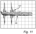
- Fig 11 is a diagram illustrating the measurement error introduced by signal interacting structures in the form of example reflectors, and includes a first curve 99 indicating the measurement error as a function of distance to the interface 13 for the first measurement channel including the first transceiver 21, and a second curve 101 indicating the measurement error as a function of distance to the interface 13 for the second measurement channel including the second transceiver 23.
- the first curve 99 indicates that the measurement error is relatively small and that the variation in measurement error is also relatively small across the measurement range.
- the second curve 101 indicates that the measurement error is considerably larger across the measurement range, and exhibits two distinct peaks in measurement error for distances corresponding to the positions of the reflectors 53a-b along the tubular waveguide 17.
Landscapes
- Physics & Mathematics (AREA)
- Engineering & Computer Science (AREA)
- Remote Sensing (AREA)
- Radar, Positioning & Navigation (AREA)
- General Physics & Mathematics (AREA)
- Electromagnetism (AREA)
- Computer Networks & Wireless Communication (AREA)
- Fluid Mechanics (AREA)
- Thermal Sciences (AREA)
- Signal Processing (AREA)
- Analytical Chemistry (AREA)
- Immunology (AREA)
- Pathology (AREA)
- General Health & Medical Sciences (AREA)
- Biochemistry (AREA)
- Chemical & Material Sciences (AREA)
- Life Sciences & Earth Sciences (AREA)
- Health & Medical Sciences (AREA)
- Measurement Of Levels Of Liquids Or Fluent Solid Materials (AREA)
Claims (12)
- Système de jauge de niveau à radar (3) destiné à la détermination d'un niveau d'une interface (13) entre un produit en phase liquide (9) et un produit en phase vapeur (11) dans un réservoir (7), et d'une distribution de densité dans ledit produit en phase liquide (9), ledit système de jauge de niveau à radar (3) comprenant :un premier émetteur-récepteur (21) destiné à générer, émettre et recevoir des signaux électromagnétiques présentant un premier ensemble de propriétés de signal ;un deuxième émetteur-récepteur (23) destiné à générer, émettre et recevoir des signaux électromagnétiques présentant un deuxième ensemble de propriétés de signal différent du premier ensemble de propriétés de signal ;une antenne (19) accouplée audit premier émetteur-récepteur (21) et audit deuxième émetteur-récepteur (23), ladite antenne (19) étant conçue pour émettre un premier signal de transmission électromagnétique (ST1) présentant ledit premier ensemble de propriétés de signal, et un deuxième signal de transmission électromagnétique (ST2) présentant ledit deuxième ensemble de propriétés de signal, et pour recevoir un premier signal de réflexion (SR1) résultant d'une réflexion du premier signal de transmission (ST1) et un deuxième signal de réflexion (SR2) résultant d'une réflexion du deuxième signal de transmission (ST2) ;un guide d'onde tubulaire (17) s'étendant à partir d'une partie supérieure du réservoir vers une partie inférieure du réservoir, ledit guide d'onde tubulaire étant conçu et configuré pour guider ledit premier signal de transmission (ST1) et ledit deuxième signal de transmission (ST2) rayonnés par ladite antenne (19) vers ladite interface (13) entre le produit en phase liquide (9) et le produit en phase vapeur (11) et dans ledit produit en phase liquide (9), et pour renvoyer ledit premier signal de réflexion (SR1) et ledit deuxième signal de réflexion (SR2) vers ladite antenne (19) ;au moins une première pluralité de structures d'interaction de signal (53a-d) disposées à des niveaux différents le long d'un premier segment (71) dudit guide d'onde tubulaire (17), chaque structure d'interaction de signal parmi ladite première pluralité de structures d'interaction de signal étant configurée pour interagir sélectivement avec ledit deuxième signal de transmission (ST2) pour contribuer audit deuxième signal de réflexion (SR2) ; etune circuiterie de traitement (25 ; 26) connectée audit premier émetteur-récepteur (21) et audit deuxième émetteur-récepteur (23), ladite circuiterie de traitement étant configurée pour déterminer ledit niveau de l'interface (13) entre le produit en phase liquide et le produit en phase vapeur sur la base d'une relation entre ledit premier signal de transmission (ST1) et ledit premier signal de réflexion (SR1), et ladite distribution de densité dans ledit produit en phase liquide (9) sur la base d'une relation entre ledit deuxième signal de transmission (ST2) et ledit deuxième signal de réflexion (SR2), ladite circuiterie de traitement (25 ; 26) étant configurée pour déterminer :une première mesure indiquant une distance entre une première structure d'interaction de signal et une deuxième structure d'interaction de signal parmi ladite première pluralité de structures d'interaction de signal (53a-d) sur la base d'une relation entre ledit deuxième signal de transmission (ST2) et ledit deuxième signal de réflexion (SR2) ;une deuxième mesure indiquant une distance entre une troisième structure d'interaction de signal et une quatrième structure d'interaction de signal parmi ladite première pluralité de structures d'interaction de signal (53a-d) sur la base d'une relation entre ledit deuxième signal de transmission (ST2) et ledit deuxième signal de réflexion (SR2) ;une première densité moyenne pour une première plage de niveau dans ledit réservoir (7) sur la base de ladite première mesure ; etune deuxième densité moyenne pour une deuxième plage de niveau dans ledit réservoir (7) sur la base de ladite deuxième mesure.
- Système de jauge de niveau à radar (3) selon la revendication 1, dans lequel ladite première pluralité de structures d'interaction de signal (53a-d) comprend au moins trois structures d'interaction de signal espacées mutuellement le long du premier segment (71) dudit guide d'onde tubulaire (17).
- Système de jauge de niveau à radar (3) selon la revendication 1, dans lequel ledit premier ensemble de propriétés de signal comprend une première polarisation, et ledit deuxième ensemble de propriétés de signal comprend une deuxième polarisation différente de ladite première polarisation.
- Système de jauge de niveau à radar (3) selon la revendication 3, dans lequel ladite première polarisation est une première polarisation linéaire, et ladite deuxième polarisation est une deuxième polarisation linéaire, orthogonale à ladite première polarisation linéaire.
- Système de jauge de niveau à radar (3) selon la revendication 1, dans lequel ledit premier ensemble de propriétés de signal comprend un premier mode de propagation, et ledit deuxième ensemble de propriétés de signal comprend un deuxième mode de propagation différent dudit premier mode de propagation.
- Système de jauge de niveau à radar (3) selon la revendication 1, dans lequel chaque structure d'interaction de signal parmi ladite première pluralité de structures d'interaction de signal (53a-d) est une structure réfléchissante conçue et configurée pour présenter un premier coefficient de réflexion pour ledit premier signal de transmission et un deuxième coefficient de réflexion pour ledit deuxième signal de transmission, un rapport entre ledit premier coefficient de réflexion et ledit deuxième coefficient de réflexion étant inférieur à 1:2.
- Système de jauge de niveau à radar (3) pour la détermination d'un niveau d'une interface (13) entre un produit en phase liquide (9) et un produit en phase vapeur (11) dans un réservoir (7), et d'une distribution de densité dans ledit produit en phase liquide (9), ledit système de jauge de niveau à radar (3) comprenant :un premier émetteur-récepteur (21) destiné à générer, émettre et recevoir des signaux électromagnétiques présentant un premier ensemble de propriétés de signal ;un deuxième émetteur-récepteur (23) destiné à générer, émettre et recevoir des signaux électromagnétiques présentant un deuxième ensemble de propriétés de signal différent du premier ensemble de propriétés de signal ;une antenne (19) accouplée audit premier émetteur-récepteur (21) et audit deuxième émetteur-récepteur (23), ladite antenne (19) étant conçue pour émettre un premier signal de transmission électromagnétique (ST1) présentant ledit premier ensemble de propriétés de signal, et un deuxième signal de transmission électromagnétique (ST2) présentant ledit deuxième ensemble de propriétés de signal, et pour recevoir un premier signal de réflexion (SR1) résultant d'une réflexion du premier signal de transmission (ST1) et un deuxième signal de réflexion (SR2) résultant d'une réflexion du deuxième signal de transmission (ST2) ;un guide d'onde tubulaire (17) s'étendant à partir d'une partie supérieure du réservoir vers une partie inférieure du réservoir, ledit guide d'onde tubulaire étant conçu et configuré pour guider ledit premier signal de transmission (ST1) et ledit deuxième signal de transmission (ST2) rayonnés par ladite antenne (19) vers ladite interface (13) entre le produit en phase liquide (9) et le produit en phase vapeur (11) et dans ledit produit en phase liquide (9), et pour renvoyer ledit premier signal de réflexion (SR1) et ledit deuxième signal de réflexion (SR2) vers ladite antenne (19) ;au moins une première pluralité de structures d'interaction de signal (57a-d) disposées à des niveaux différents le long d'un premier segment (71) dudit guide d'onde tubulaire (17), chaque structure d'interaction de signal parmi ladite première pluralité de structures d'interaction de signal étant configurée pour interagir sélectivement avec ledit deuxième signal de transmission (ST2) pour contribuer audit deuxième signal de réflexion (SR2) ; etune circuiterie de traitement (25 ; 26) connectée audit premier émetteur-récepteur (21) et audit deuxième émetteur-récepteur (23), ladite circuiterie de traitement étant configurée pour déterminer ledit niveau de l'interface (13) entre le produit en phase liquide et le produit en phase vapeur sur la base d'une relation entre ledit premier signal de transmission (ST1) et ledit premier signal de réflexion (SR1), et ladite distribution de densité dans ledit produit en phase liquide (9) sur la base d'une relation entre ledit deuxième signal de transmission (ST2) et ledit deuxième signal de réflexion (SR2), dans lequel :ledit guide d'onde tubulaire (17) comprend au moins une première pluralité d'ouvertures pour permettre sélectivement à un champ électromagnétique résultant dudit deuxième signal de transmission (ST2) d'être présente sur un côté extérieur dudit guide d'onde tubulaire (17) au niveau de chaque ouverture dans ladite première pluralité d'ouvertures ; etchaque structure d'interaction de signal (57a-d) parmi ladite première pluralité de structures d'interaction de signal est disposée sur le côté extérieur dudit guide d'onde tubulaire (17) au niveau de chaque ouverture parmi ladite première pluralité d'ouvertures, afin de pouvoir être excitée par ledit deuxième signal de transmission (ST2) .
- Système de jauge de niveau à radar (3) selon la revendication 7, dans lequel chaque structure d'interaction de signal (57a-d) parmi ladite première pluralité de structures d'interaction de signal est un résonateur conçu et configuré pour pouvoir être excité uniquement par ledit deuxième signal de transmission (ST2), une fréquence de résonance dudit résonateur indiquant une densité du produit en phase liquide (9) remplissant ledit résonateur.
- Système de jauge de niveau à radar (3) selon la revendication 8, dans lequel ledit résonateur comprend une cavité de résonateur conçue pour contenir ledit produit en phase liquide lorsque celle-ci est submergée dans ledit produit en phase liquide (9).
- Système de jauge de niveau à radar (3) selon la revendication 8, dans lequel ladite circuiterie de traitement (25 ; 26) est configurée pour déterminer :une première densité pour un premier niveau dans ledit réservoir sur la base d'une fréquence de résonance d'un premier résonateur disposé audit premier niveau ; etune deuxième densité pour un deuxième niveau dans ledit réservoir sur la base d'une fréquence de résonance d'un deuxième résonateur disposé audit deuxième niveau.
- Système de jauge de niveau à radar (3) pour la détermination d'un niveau d'une interface (13) entre un produit en phase liquide (9) et un produit en phase vapeur (11) dans un réservoir (7), et d'une distribution de densité dans ledit produit en phase liquide (9), ledit système de jauge de niveau à radar (3) comprenant :un premier émetteur-récepteur (21) destiné à générer, émettre et recevoir des signaux électromagnétiques présentant un premier ensemble de propriétés de signal ;un deuxième émetteur-récepteur (23) destiné à générer, émettre et recevoir des signaux électromagnétiques présentant un deuxième ensemble de propriétés de signal différent du premier ensemble de propriétés de signal ;une antenne (19) accouplée audit premier émetteur-récepteur (21) et audit deuxième émetteur-récepteur (23), ladite antenne (19) étant conçue pour émettre un premier signal de transmission électromagnétique (ST1) présentant ledit premier ensemble de propriétés de signal, et un deuxième signal de transmission électromagnétique (ST2) présentant ledit deuxième ensemble de propriétés de signal, et pour recevoir un premier signal de réflexion (SR1) résultant d'une réflexion du premier signal de transmission (ST1) et un deuxième signal de réflexion (SR2) résultant d'une réflexion du deuxième signal de transmission (ST2) ;un guide d'onde tubulaire (17) s'étendant à partir d'une partie supérieure du réservoir vers une partie inférieure du réservoir, ledit guide d'onde tubulaire étant conçu et configuré pour guider ledit premier signal de transmission (ST1) et ledit deuxième signal de transmission (ST2) rayonnés par ladite antenne (19) vers ladite interface (13) entre le produit en phase liquide (9) et le produit en phase vapeur (11) et dans ledit produit en phase liquide (9), et pour renvoyer ledit premier signal de réflexion (SR1) et ledit deuxième signal de réflexion (SR2) vers ladite antenne (19) ;au moins une première pluralité de structures d'interaction de signal (53a-d) disposées à des niveaux différents le long d'un premier segment (71) dudit guide d'onde tubulaire (17), chaque structure d'interaction de signal parmi ladite première pluralité de structures d'interaction de signal étant configurée pour interagir sélectivement avec ledit deuxième signal de transmission (ST2) afin de contribuer audit deuxième signal de réflexion (SR2) ; etune circuiterie de traitement (25 ; 26) connectée audit premier émetteur-récepteur (21) et audit deuxième émetteur-récepteur (23), ladite circuiterie de traitement étant configurée pour déterminer ledit niveau de l'interface (13) entre le produit en phase liquide et le produit en phase vapeur sur la base d'une relation entre ledit premier signal de transmission (ST1) et ledit premier signal de réflexion (SR1), et ladite distribution de densité dans ledit produit en phase liquide (9) sur la base d'une relation entre ledit deuxième signal de transmission (ST2) et ledit deuxième signal de réflexion (SR2), dans lequel :ledit système de jauge de niveau à radar (3) comprend en outre une deuxième pluralité de structures d'interaction de signal (53e-h) disposées à des niveaux différents le long d'un deuxième segment (73) dudit guide d'onde tubulaire (17) différent dudit premier segment (71), chaque structure d'interaction de signal parmi ladite deuxième pluralité de structures d'interaction de signal (53e-h) étant configurée pour interagir sélectivement avec ledit premier signal de transmission (ST1) afin de contribuer audit premier signal de réflexion (SR1) ; etladite circuiterie de traitement (25 ; 26) est configurée pour :déterminer, pour des niveaux le long dudit premier segment (71) dudit guide d'onde tubulaire (17), ledit niveau de l'interface (13) entre le produit en phase liquide (9) et le produit en phase vapeur (11) sur la base d'une relation entre ledit premier signal de transmission (ST1) et ledit premier signal de réflexion (SR1), et ladite distribution de densité dans ledit produit en phase liquide (9) sur la base dudit deuxième signal de réflexion (SR2) ; etdéterminer, pour des niveaux le long dudit deuxième segment (73) dudit guide d'onde tubulaire (17), ledit niveau de l'interface (13) entre le produit en phase liquide (9) et le produit en phase vapeur (11) sur la base d'une relation entre ledit deuxième signal de transmission (ST2) et ledit deuxième signal de réflexion (SR2), et ladite distribution de densité dans ledit produit en phase liquide (9) sur la base dudit premier signal de réflexion (SR1).
- Procédé de détermination d'un niveau d'une interface (13) entre un produit en phase liquide (9) et un produit en phase vapeur (11) dans un réservoir (7), et d'une distribution de densité dans ledit produit en phase liquide (9), à l'aide d'un système de jauge de niveau à radar (3) comprenant : un premier émetteur-récepteur (21) ; un deuxième émetteur-récepteur (23) ; une antenne (19) accouplée audit premier émetteur-récepteur (21) et audit deuxième émetteur-récepteur (23) ; un guide d'onde tubulaire (17) s'étendant à partir d'une partie supérieure du réservoir vers une partie inférieure du réservoir ; au moins une première pluralité de structures d'interaction de signal (53ad) disposées à des niveaux différents le long d'un premier segment (71) dudit guide d'onde tubulaire (17), chaque structure d'interaction de signal parmi ladite première pluralité de structures d'interaction de signal (53a-d) étant configurée pour interagir avec des signaux électromagnétiques présentant un ensemble donné de propriétés de signal ; et une circuiterie de traitement (25 ; 26) connectée audit premier émetteur-récepteur (21) et audit deuxième émetteur-récepteur (23),
ledit procédé comprenant les étapes suivantes :émission (S1), par ledit premier émetteur-récepteur (21), d'un premier signal de transmission électromagnétique (ST1) présentant un premier ensemble de propriétés de signal différent dudit ensemble donné de propriétés de signal ;émission (S2), par ledit deuxième émetteur-récepteur (23), d'un deuxième signal de transmission électromagnétique (ST2) présentant un deuxième ensemble de propriétés de signal constituant ledit ensemble donné de propriétés de signal ;rayonnement (S3), par ladite antenne (19), dudit premier signal de transmission (ST1) et dudit deuxième signal de transmission (ST2) dans ledit guide d'onde tubulaire (17) ;réception (S4, S5), par ladite antenne (19), d'un premier signal de réflexion électromagnétique (SR1) résultant d'une réflexion dudit premier signal de transmission (ST1), et d'un deuxième signal de réflexion électromagnétique (SR2) résultant d'une réflexion dudit deuxième signal de transmission (ST2) ;détermination (S6), par ladite circuiterie de traitement (25 ; 26), dudit niveau de l'interface (13) entre le produit en phase liquide et le produit en phase vapeur sur la base d'une relation entre ledit premier signal de transmission (ST1) et ledit premier signal de réflexion (SR1) ;détermination d'une première mesure indiquant une distance entre une première structure d'interaction de signal et une deuxième structure d'interaction de signal parmi ladite première pluralité de structures d'interaction de signal (53a-d) sur la base d'une relation entre ledit deuxième signal de transmission (ST2) et ledit deuxième signal de réflexion (SR2) ;détermination d'une deuxième mesure indiquant une distance entre une troisième structure d'interaction de signal et une quatrième structure d'interaction de signal parmi ladite première pluralité de structures d'interaction de signal (53a-d) sur la base d'une relation entre ledit deuxième signal de transmission (ST2) et ledit deuxième signal de réflexion (SR2) ;détermination d'une première densité moyenne pour une première plage de niveau dans ledit réservoir sur la base de ladite première mesure ; etdétermination d'une deuxième densité moyenne pour une deuxième plage de niveau dans ledit réservoir sur la base de ladite deuxième mesure.
Applications Claiming Priority (2)
| Application Number | Priority Date | Filing Date | Title |
|---|---|---|---|
| US16/140,783 US10801873B2 (en) | 2018-09-25 | 2018-09-25 | System and method for determining level and density distribution |
| PCT/EP2019/074626 WO2020064385A1 (fr) | 2018-09-25 | 2019-09-16 | Système et procédé de détermination d'une distribution de niveau et de densité |
Publications (2)
| Publication Number | Publication Date |
|---|---|
| EP3857183A1 EP3857183A1 (fr) | 2021-08-04 |
| EP3857183B1 true EP3857183B1 (fr) | 2023-07-26 |
Family
ID=67933875
Family Applications (1)
| Application Number | Title | Priority Date | Filing Date |
|---|---|---|---|
| EP19769782.4A Active EP3857183B1 (fr) | 2018-09-25 | 2019-09-16 | Système et procédé de détermination d'une distribution de niveau et de densité |
Country Status (4)
| Country | Link |
|---|---|
| US (1) | US10801873B2 (fr) |
| EP (1) | EP3857183B1 (fr) |
| CN (2) | CN110940394B (fr) |
| WO (1) | WO2020064385A1 (fr) |
Cited By (1)
| Publication number | Priority date | Publication date | Assignee | Title |
|---|---|---|---|---|
| DE102023102306A1 (de) | 2023-01-31 | 2024-08-01 | Ifm Electronic Gmbh | Messverfahren und Messanordnung |
Families Citing this family (9)
| Publication number | Priority date | Publication date | Assignee | Title |
|---|---|---|---|---|
| US10801873B2 (en) * | 2018-09-25 | 2020-10-13 | Rosemount Tank Radar Ab | System and method for determining level and density distribution |
| GB201912707D0 (en) * | 2019-09-04 | 2019-10-16 | Johnson Matthey Plc | Level measurement instrument |
| EP4375625A1 (fr) * | 2022-11-24 | 2024-05-29 | Rosemount Tank Radar AB | Système de jauge de niveau radar pour la propagation de plusieurs signaux d'émission générés individuellement par une antenne commune |
| US12422295B2 (en) * | 2024-01-27 | 2025-09-23 | Barrel Proof Technologies Llc | System and method for determining content utilizing externally mounted container monitoring system |
| US12117329B1 (en) * | 2024-01-27 | 2024-10-15 | Barrel Proof Technologies Llc | Container monitoring system and method thereof |
| US12609185B2 (en) | 2024-01-27 | 2026-04-21 | Barrel Proof Technologies Llc | Artificial intelligence driven monitoring system for aging whiskey |
| US12228445B1 (en) * | 2024-01-27 | 2025-02-18 | Barrel Proof Technologies Llc | System and method for determining alcohol content within container utilizing container monitoring system |
| US12228525B1 (en) * | 2024-01-27 | 2025-02-18 | Barrel Proof Technologies Llc | System and method for determining alcohol content utilizing container monitoring system |
| CN120846192A (zh) * | 2025-07-08 | 2025-10-28 | 深圳水木清研智能科技有限公司 | 基于探测雷达的粮食仓储监测方法、装置、设备及介质 |
Family Cites Families (19)
| Publication number | Priority date | Publication date | Assignee | Title |
|---|---|---|---|---|
| SE461179B (sv) | 1989-02-08 | 1990-01-15 | Saab Marine Electronics | Anordning foer maetning av nivaan av ett i en behaallare befintligt fluidum |
| SE504682C2 (sv) | 1991-07-04 | 1997-04-07 | Saab Marine Electronics | Anordning för mätning av nivån av ett i en behållare befintligt medium |
| US6915689B2 (en) | 2002-11-21 | 2005-07-12 | Saab Rosemount Tank Radar Ab | Apparatus and method for radar-based level gauging |
| US7106247B2 (en) | 2003-10-20 | 2006-09-12 | Saab Rosemount Tank Radar Ab | Radar level gauge with antenna arrangement for improved radar level gauging |
| US7345622B2 (en) | 2005-10-14 | 2008-03-18 | Saab Rosemount Tank Radar Ab | Two-mode radar level gauge system |
| US7532155B2 (en) | 2006-04-10 | 2009-05-12 | Rosemount Tank Radar Ab | Radar level gauging system |
| US20080150789A1 (en) * | 2006-12-21 | 2008-06-26 | Anders Jirskog | Radar level gauge system |
| US7701385B2 (en) | 2008-05-22 | 2010-04-20 | Rosemount Tank Radar Ab | Multi-channel radar level gauge system |
| NO331262B1 (no) | 2010-04-12 | 2011-11-14 | Kongsberg Maritime As | Metode og apparat for å måle tettheten til en væske |
| US8350752B2 (en) * | 2010-07-09 | 2013-01-08 | Rosemount Tank Radar Ab | Radar level gauge system with bottom reflector and bottom reflector |
| US8842038B2 (en) * | 2010-12-30 | 2014-09-23 | Rosemount Tank Radar Ab | High frequency mode generator for radar level gauge |
| US8800363B2 (en) * | 2010-12-02 | 2014-08-12 | Rosemount Tank Radar Ab | Radar level gauge with dielectric rod connection |
| US8773302B2 (en) | 2011-07-07 | 2014-07-08 | Rosemount Tank Radar Ab | Multi-channel radar level gauge |
| US8933835B2 (en) * | 2012-09-25 | 2015-01-13 | Rosemount Tank Radar Ab | Two-channel directional antenna and a radar level gauge with such an antenna |
| CN203298828U (zh) * | 2013-01-21 | 2013-11-20 | 北京乾达源科技有限公司 | 一种罐体液位和界位的测量装置 |
| CN103090929A (zh) * | 2013-01-21 | 2013-05-08 | 北京乾达源科技有限公司 | 一种罐体液位和界位的测量方法 |
| US9410904B2 (en) * | 2013-12-23 | 2016-08-09 | Rosmount Tank Radar Ab | System and method for determining density of a medium in a tank |
| US9778089B2 (en) * | 2014-06-30 | 2017-10-03 | Rosemount Tank Radar Ab | Multi-channel guided wave radar level gauge |
| US10801873B2 (en) * | 2018-09-25 | 2020-10-13 | Rosemount Tank Radar Ab | System and method for determining level and density distribution |
-
2018
- 2018-09-25 US US16/140,783 patent/US10801873B2/en active Active
- 2018-11-14 CN CN201811353705.6A patent/CN110940394B/zh active Active
- 2018-11-14 CN CN201821872914.7U patent/CN209416451U/zh active Active
-
2019
- 2019-09-16 WO PCT/EP2019/074626 patent/WO2020064385A1/fr not_active Ceased
- 2019-09-16 EP EP19769782.4A patent/EP3857183B1/fr active Active
Cited By (1)
| Publication number | Priority date | Publication date | Assignee | Title |
|---|---|---|---|---|
| DE102023102306A1 (de) | 2023-01-31 | 2024-08-01 | Ifm Electronic Gmbh | Messverfahren und Messanordnung |
Also Published As
| Publication number | Publication date |
|---|---|
| US20200096378A1 (en) | 2020-03-26 |
| CN110940394B (zh) | 2025-09-12 |
| EP3857183A1 (fr) | 2021-08-04 |
| US10801873B2 (en) | 2020-10-13 |
| CN110940394A (zh) | 2020-03-31 |
| WO2020064385A1 (fr) | 2020-04-02 |
| CN209416451U (zh) | 2019-09-20 |
Similar Documents
| Publication | Publication Date | Title |
|---|---|---|
| EP3857183B1 (fr) | Système et procédé de détermination d'une distribution de niveau et de densité | |
| EP2283382B1 (fr) | Système de jauge de niveau à radar modulé en fréquence de haute sensibilité | |
| KR101680161B1 (ko) | 주기적으로 배열된 기준 임피던스 트랜지션을 갖는 웨이브가이딩 구조를 이용한 레이더 레벨 게이지 시스템 | |
| EP2359102B1 (fr) | Système et procédé de détermination d'un niveau de remplissage | |
| US7855676B2 (en) | Radar level gauge system with leakage detection | |
| EP2659237B1 (fr) | Générateur de mode à haute fréquence pour indicateur radar de niveau | |
| EP3301412B1 (fr) | Système de mesure de niveau radar à ondes guidées avec deux sondes à ligne de transmission pour compensation de la constante diélectrique | |
| EP3021092B1 (fr) | Système jauge de niveau du type radar à ondes guidées doté d'une extrémité de sonde à réflexion réduite | |
| US6614391B1 (en) | Device for determining the fill level of a filling substance in a container | |
| RU2327958C2 (ru) | Устройство и способ измерения уровня на основе радиолокации | |
| EP3814729B1 (fr) | Jauge de niveau radar à transducteur d'ondes de mode h01 | |
| EP3425350B1 (fr) | Système de jauge de niveau radar à agencement d'espacement à faible réflexion | |
| CN113108866B (zh) | 导波雷达物位计和用于控制导波雷达物位计的方法 | |
| US10677634B2 (en) | Radar level gauge system having longitudinally open two-conductor probe and method of assembly | |
| EP3959490B1 (fr) | Capteur de niveau radar à impulsions présentant une résistance améliorée à une perturbation de signal |
Legal Events
| Date | Code | Title | Description |
|---|---|---|---|
| STAA | Information on the status of an ep patent application or granted ep patent |
Free format text: STATUS: UNKNOWN |
|
| STAA | Information on the status of an ep patent application or granted ep patent |
Free format text: STATUS: THE INTERNATIONAL PUBLICATION HAS BEEN MADE |
|
| PUAI | Public reference made under article 153(3) epc to a published international application that has entered the european phase |
Free format text: ORIGINAL CODE: 0009012 |
|
| STAA | Information on the status of an ep patent application or granted ep patent |
Free format text: STATUS: REQUEST FOR EXAMINATION WAS MADE |
|
| 17P | Request for examination filed |
Effective date: 20210308 |
|
| AK | Designated contracting states |
Kind code of ref document: A1 Designated state(s): AL AT BE BG CH CY CZ DE DK EE ES FI FR GB GR HR HU IE IS IT LI LT LU LV MC MK MT NL NO PL PT RO RS SE SI SK SM TR |
|
| DAV | Request for validation of the european patent (deleted) | ||
| DAX | Request for extension of the european patent (deleted) | ||
| GRAP | Despatch of communication of intention to grant a patent |
Free format text: ORIGINAL CODE: EPIDOSNIGR1 |
|
| STAA | Information on the status of an ep patent application or granted ep patent |
Free format text: STATUS: GRANT OF PATENT IS INTENDED |
|
| RIC1 | Information provided on ipc code assigned before grant |
Ipc: G01N 9/24 20060101ALN20230207BHEP Ipc: G01S 13/34 20060101ALI20230207BHEP Ipc: G01S 7/41 20060101ALI20230207BHEP Ipc: G01S 7/02 20060101ALI20230207BHEP Ipc: G01F 23/80 20220101ALI20230207BHEP Ipc: G01S 13/88 20060101ALI20230207BHEP Ipc: G01F 23/284 20060101ALI20230207BHEP Ipc: G01F 23/00 20060101AFI20230207BHEP |
|
| INTG | Intention to grant announced |
Effective date: 20230222 |
|
| GRAS | Grant fee paid |
Free format text: ORIGINAL CODE: EPIDOSNIGR3 |
|
| GRAA | (expected) grant |
Free format text: ORIGINAL CODE: 0009210 |
|
| STAA | Information on the status of an ep patent application or granted ep patent |
Free format text: STATUS: THE PATENT HAS BEEN GRANTED |
|
| AK | Designated contracting states |
Kind code of ref document: B1 Designated state(s): AL AT BE BG CH CY CZ DE DK EE ES FI FR GB GR HR HU IE IS IT LI LT LU LV MC MK MT NL NO PL PT RO RS SE SI SK SM TR |
|
| REG | Reference to a national code |
Ref country code: CH Ref legal event code: EP |
|
| REG | Reference to a national code |
Ref country code: IE Ref legal event code: FG4D |
|
| REG | Reference to a national code |
Ref country code: DE Ref legal event code: R096 Ref document number: 602019033616 Country of ref document: DE |
|
| REG | Reference to a national code |
Ref country code: LT Ref legal event code: MG9D |
|
| REG | Reference to a national code |
Ref country code: NL Ref legal event code: MP Effective date: 20230726 |
|
| REG | Reference to a national code |
Ref country code: AT Ref legal event code: MK05 Ref document number: 1592412 Country of ref document: AT Kind code of ref document: T Effective date: 20230726 |
|
| PG25 | Lapsed in a contracting state [announced via postgrant information from national office to epo] |
Ref country code: NL Free format text: LAPSE BECAUSE OF FAILURE TO SUBMIT A TRANSLATION OF THE DESCRIPTION OR TO PAY THE FEE WITHIN THE PRESCRIBED TIME-LIMIT Effective date: 20230726 |
|
| PG25 | Lapsed in a contracting state [announced via postgrant information from national office to epo] |
Ref country code: GR Free format text: LAPSE BECAUSE OF FAILURE TO SUBMIT A TRANSLATION OF THE DESCRIPTION OR TO PAY THE FEE WITHIN THE PRESCRIBED TIME-LIMIT Effective date: 20231027 |
|
| PG25 | Lapsed in a contracting state [announced via postgrant information from national office to epo] |
Ref country code: IS Free format text: LAPSE BECAUSE OF FAILURE TO SUBMIT A TRANSLATION OF THE DESCRIPTION OR TO PAY THE FEE WITHIN THE PRESCRIBED TIME-LIMIT Effective date: 20231126 |
|
| PG25 | Lapsed in a contracting state [announced via postgrant information from national office to epo] |
Ref country code: SE Free format text: LAPSE BECAUSE OF FAILURE TO SUBMIT A TRANSLATION OF THE DESCRIPTION OR TO PAY THE FEE WITHIN THE PRESCRIBED TIME-LIMIT Effective date: 20230726 Ref country code: RS Free format text: LAPSE BECAUSE OF FAILURE TO SUBMIT A TRANSLATION OF THE DESCRIPTION OR TO PAY THE FEE WITHIN THE PRESCRIBED TIME-LIMIT Effective date: 20230726 Ref country code: PT Free format text: LAPSE BECAUSE OF FAILURE TO SUBMIT A TRANSLATION OF THE DESCRIPTION OR TO PAY THE FEE WITHIN THE PRESCRIBED TIME-LIMIT Effective date: 20231127 Ref country code: NO Free format text: LAPSE BECAUSE OF FAILURE TO SUBMIT A TRANSLATION OF THE DESCRIPTION OR TO PAY THE FEE WITHIN THE PRESCRIBED TIME-LIMIT Effective date: 20231026 Ref country code: LV Free format text: LAPSE BECAUSE OF FAILURE TO SUBMIT A TRANSLATION OF THE DESCRIPTION OR TO PAY THE FEE WITHIN THE PRESCRIBED TIME-LIMIT Effective date: 20230726 Ref country code: LT Free format text: LAPSE BECAUSE OF FAILURE TO SUBMIT A TRANSLATION OF THE DESCRIPTION OR TO PAY THE FEE WITHIN THE PRESCRIBED TIME-LIMIT Effective date: 20230726 Ref country code: IS Free format text: LAPSE BECAUSE OF FAILURE TO SUBMIT A TRANSLATION OF THE DESCRIPTION OR TO PAY THE FEE WITHIN THE PRESCRIBED TIME-LIMIT Effective date: 20231126 Ref country code: HR Free format text: LAPSE BECAUSE OF FAILURE TO SUBMIT A TRANSLATION OF THE DESCRIPTION OR TO PAY THE FEE WITHIN THE PRESCRIBED TIME-LIMIT Effective date: 20230726 Ref country code: GR Free format text: LAPSE BECAUSE OF FAILURE TO SUBMIT A TRANSLATION OF THE DESCRIPTION OR TO PAY THE FEE WITHIN THE PRESCRIBED TIME-LIMIT Effective date: 20231027 Ref country code: FI Free format text: LAPSE BECAUSE OF FAILURE TO SUBMIT A TRANSLATION OF THE DESCRIPTION OR TO PAY THE FEE WITHIN THE PRESCRIBED TIME-LIMIT Effective date: 20230726 Ref country code: AT Free format text: LAPSE BECAUSE OF FAILURE TO SUBMIT A TRANSLATION OF THE DESCRIPTION OR TO PAY THE FEE WITHIN THE PRESCRIBED TIME-LIMIT Effective date: 20230726 |
|
| PG25 | Lapsed in a contracting state [announced via postgrant information from national office to epo] |
Ref country code: PL Free format text: LAPSE BECAUSE OF FAILURE TO SUBMIT A TRANSLATION OF THE DESCRIPTION OR TO PAY THE FEE WITHIN THE PRESCRIBED TIME-LIMIT Effective date: 20230726 |
|
| PG25 | Lapsed in a contracting state [announced via postgrant information from national office to epo] |
Ref country code: ES Free format text: LAPSE BECAUSE OF FAILURE TO SUBMIT A TRANSLATION OF THE DESCRIPTION OR TO PAY THE FEE WITHIN THE PRESCRIBED TIME-LIMIT Effective date: 20230726 |
|
| REG | Reference to a national code |
Ref country code: DE Ref legal event code: R097 Ref document number: 602019033616 Country of ref document: DE |
|
| PG25 | Lapsed in a contracting state [announced via postgrant information from national office to epo] |
Ref country code: SM Free format text: LAPSE BECAUSE OF FAILURE TO SUBMIT A TRANSLATION OF THE DESCRIPTION OR TO PAY THE FEE WITHIN THE PRESCRIBED TIME-LIMIT Effective date: 20230726 Ref country code: RO Free format text: LAPSE BECAUSE OF FAILURE TO SUBMIT A TRANSLATION OF THE DESCRIPTION OR TO PAY THE FEE WITHIN THE PRESCRIBED TIME-LIMIT Effective date: 20230726 Ref country code: ES Free format text: LAPSE BECAUSE OF FAILURE TO SUBMIT A TRANSLATION OF THE DESCRIPTION OR TO PAY THE FEE WITHIN THE PRESCRIBED TIME-LIMIT Effective date: 20230726 Ref country code: EE Free format text: LAPSE BECAUSE OF FAILURE TO SUBMIT A TRANSLATION OF THE DESCRIPTION OR TO PAY THE FEE WITHIN THE PRESCRIBED TIME-LIMIT Effective date: 20230726 Ref country code: DK Free format text: LAPSE BECAUSE OF FAILURE TO SUBMIT A TRANSLATION OF THE DESCRIPTION OR TO PAY THE FEE WITHIN THE PRESCRIBED TIME-LIMIT Effective date: 20230726 Ref country code: CZ Free format text: LAPSE BECAUSE OF FAILURE TO SUBMIT A TRANSLATION OF THE DESCRIPTION OR TO PAY THE FEE WITHIN THE PRESCRIBED TIME-LIMIT Effective date: 20230726 Ref country code: SK Free format text: LAPSE BECAUSE OF FAILURE TO SUBMIT A TRANSLATION OF THE DESCRIPTION OR TO PAY THE FEE WITHIN THE PRESCRIBED TIME-LIMIT Effective date: 20230726 |
|
| PG25 | Lapsed in a contracting state [announced via postgrant information from national office to epo] |
Ref country code: LU Free format text: LAPSE BECAUSE OF NON-PAYMENT OF DUE FEES Effective date: 20230916 |
|
| REG | Reference to a national code |
Ref country code: BE Ref legal event code: MM Effective date: 20230930 |
|
| PG25 | Lapsed in a contracting state [announced via postgrant information from national office to epo] |
Ref country code: LU Free format text: LAPSE BECAUSE OF NON-PAYMENT OF DUE FEES Effective date: 20230916 Ref country code: IT Free format text: LAPSE BECAUSE OF FAILURE TO SUBMIT A TRANSLATION OF THE DESCRIPTION OR TO PAY THE FEE WITHIN THE PRESCRIBED TIME-LIMIT Effective date: 20230726 Ref country code: MC Free format text: LAPSE BECAUSE OF FAILURE TO SUBMIT A TRANSLATION OF THE DESCRIPTION OR TO PAY THE FEE WITHIN THE PRESCRIBED TIME-LIMIT Effective date: 20230726 |
|
| PLBE | No opposition filed within time limit |
Free format text: ORIGINAL CODE: 0009261 |
|
| STAA | Information on the status of an ep patent application or granted ep patent |
Free format text: STATUS: NO OPPOSITION FILED WITHIN TIME LIMIT |
|
| GBPC | Gb: european patent ceased through non-payment of renewal fee |
Effective date: 20231026 |
|
| 26N | No opposition filed |
Effective date: 20240429 |
|
| REG | Reference to a national code |
Ref country code: IE Ref legal event code: MM4A |
|
| PG25 | Lapsed in a contracting state [announced via postgrant information from national office to epo] |
Ref country code: IE Free format text: LAPSE BECAUSE OF NON-PAYMENT OF DUE FEES Effective date: 20230916 |
|
| PG25 | Lapsed in a contracting state [announced via postgrant information from national office to epo] |
Ref country code: GB Free format text: LAPSE BECAUSE OF NON-PAYMENT OF DUE FEES Effective date: 20231026 |
|
| PG25 | Lapsed in a contracting state [announced via postgrant information from national office to epo] |
Ref country code: IE Free format text: LAPSE BECAUSE OF NON-PAYMENT OF DUE FEES Effective date: 20230916 Ref country code: GB Free format text: LAPSE BECAUSE OF NON-PAYMENT OF DUE FEES Effective date: 20231026 Ref country code: FR Free format text: LAPSE BECAUSE OF NON-PAYMENT OF DUE FEES Effective date: 20230926 Ref country code: SI Free format text: LAPSE BECAUSE OF FAILURE TO SUBMIT A TRANSLATION OF THE DESCRIPTION OR TO PAY THE FEE WITHIN THE PRESCRIBED TIME-LIMIT Effective date: 20230726 |
|
| PG25 | Lapsed in a contracting state [announced via postgrant information from national office to epo] |
Ref country code: BE Free format text: LAPSE BECAUSE OF NON-PAYMENT OF DUE FEES Effective date: 20230930 |
|
| PG25 | Lapsed in a contracting state [announced via postgrant information from national office to epo] |
Ref country code: BG Free format text: LAPSE BECAUSE OF FAILURE TO SUBMIT A TRANSLATION OF THE DESCRIPTION OR TO PAY THE FEE WITHIN THE PRESCRIBED TIME-LIMIT Effective date: 20230726 |
|
| PG25 | Lapsed in a contracting state [announced via postgrant information from national office to epo] |
Ref country code: BG Free format text: LAPSE BECAUSE OF FAILURE TO SUBMIT A TRANSLATION OF THE DESCRIPTION OR TO PAY THE FEE WITHIN THE PRESCRIBED TIME-LIMIT Effective date: 20230726 |
|
| PGFP | Annual fee paid to national office [announced via postgrant information from national office to epo] |
Ref country code: CH Payment date: 20241001 Year of fee payment: 6 |
|
| PG25 | Lapsed in a contracting state [announced via postgrant information from national office to epo] |
Ref country code: CY Free format text: LAPSE BECAUSE OF FAILURE TO SUBMIT A TRANSLATION OF THE DESCRIPTION OR TO PAY THE FEE WITHIN THE PRESCRIBED TIME-LIMIT; INVALID AB INITIO Effective date: 20190916 |
|
| PG25 | Lapsed in a contracting state [announced via postgrant information from national office to epo] |
Ref country code: HU Free format text: LAPSE BECAUSE OF FAILURE TO SUBMIT A TRANSLATION OF THE DESCRIPTION OR TO PAY THE FEE WITHIN THE PRESCRIBED TIME-LIMIT; INVALID AB INITIO Effective date: 20190916 |
|
| PGFP | Annual fee paid to national office [announced via postgrant information from national office to epo] |
Ref country code: DE Payment date: 20250820 Year of fee payment: 7 |
|
| PG25 | Lapsed in a contracting state [announced via postgrant information from national office to epo] |
Ref country code: TR Free format text: LAPSE BECAUSE OF FAILURE TO SUBMIT A TRANSLATION OF THE DESCRIPTION OR TO PAY THE FEE WITHIN THE PRESCRIBED TIME-LIMIT Effective date: 20230726 |