EP3857231B1 - Analytquantifizierung - Google Patents
Analytquantifizierung Download PDFInfo
- Publication number
- EP3857231B1 EP3857231B1 EP19866629.9A EP19866629A EP3857231B1 EP 3857231 B1 EP3857231 B1 EP 3857231B1 EP 19866629 A EP19866629 A EP 19866629A EP 3857231 B1 EP3857231 B1 EP 3857231B1
- Authority
- EP
- European Patent Office
- Prior art keywords
- highly
- analyte
- lateral flow
- sample
- doped
- Prior art date
- Legal status (The legal status is an assumption and is not a legal conclusion. Google has not performed a legal analysis and makes no representation as to the accuracy of the status listed.)
- Active
Links
Images





Classifications
-
- G—PHYSICS
- G01—MEASURING; TESTING
- G01N—INVESTIGATING OR ANALYSING MATERIALS BY DETERMINING THEIR CHEMICAL OR PHYSICAL PROPERTIES
- G01N33/00—Investigating or analysing materials by specific methods not covered by groups G01N1/00 - G01N31/00
- G01N33/48—Biological material, e.g. blood, urine; Haemocytometers
- G01N33/50—Chemical analysis of biological material, e.g. blood, urine; Testing involving biospecific ligand binding methods; Immunological testing
- G01N33/53—Immunoassay; Biospecific binding assay; Materials therefor
- G01N33/5302—Apparatus specially adapted for immunological test procedures
-
- G—PHYSICS
- G01—MEASURING; TESTING
- G01N—INVESTIGATING OR ANALYSING MATERIALS BY DETERMINING THEIR CHEMICAL OR PHYSICAL PROPERTIES
- G01N33/00—Investigating or analysing materials by specific methods not covered by groups G01N1/00 - G01N31/00
- G01N33/48—Biological material, e.g. blood, urine; Haemocytometers
- G01N33/50—Chemical analysis of biological material, e.g. blood, urine; Testing involving biospecific ligand binding methods; Immunological testing
- G01N33/53—Immunoassay; Biospecific binding assay; Materials therefor
- G01N33/543—Immunoassay; Biospecific binding assay; Materials therefor with an insoluble carrier for immobilising immunochemicals
- G01N33/54313—Immunoassay; Biospecific binding assay; Materials therefor with an insoluble carrier for immobilising immunochemicals the carrier being characterised by its particulate form
- G01N33/54346—Nanoparticles
-
- G—PHYSICS
- G01—MEASURING; TESTING
- G01N—INVESTIGATING OR ANALYSING MATERIALS BY DETERMINING THEIR CHEMICAL OR PHYSICAL PROPERTIES
- G01N33/00—Investigating or analysing materials by specific methods not covered by groups G01N1/00 - G01N31/00
- G01N33/48—Biological material, e.g. blood, urine; Haemocytometers
- G01N33/50—Chemical analysis of biological material, e.g. blood, urine; Testing involving biospecific ligand binding methods; Immunological testing
- G01N33/53—Immunoassay; Biospecific binding assay; Materials therefor
- G01N33/543—Immunoassay; Biospecific binding assay; Materials therefor with an insoluble carrier for immobilising immunochemicals
- G01N33/54366—Apparatus specially adapted for solid-phase testing
- G01N33/54386—Analytical elements
- G01N33/54387—Immunochromatographic test strips
- G01N33/54388—Immunochromatographic test strips based on lateral flow
-
- B—PERFORMING OPERATIONS; TRANSPORTING
- B82—NANOTECHNOLOGY
- B82Y—SPECIFIC USES OR APPLICATIONS OF NANOSTRUCTURES; MEASUREMENT OR ANALYSIS OF NANOSTRUCTURES; MANUFACTURE OR TREATMENT OF NANOSTRUCTURES
- B82Y30/00—Nanotechnology for materials or surface science, e.g. nanocomposites
-
- B—PERFORMING OPERATIONS; TRANSPORTING
- B82—NANOTECHNOLOGY
- B82Y—SPECIFIC USES OR APPLICATIONS OF NANOSTRUCTURES; MEASUREMENT OR ANALYSIS OF NANOSTRUCTURES; MANUFACTURE OR TREATMENT OF NANOSTRUCTURES
- B82Y5/00—Nanobiotechnology or nanomedicine, e.g. protein engineering or drug delivery
-
- G—PHYSICS
- G01—MEASURING; TESTING
- G01N—INVESTIGATING OR ANALYSING MATERIALS BY DETERMINING THEIR CHEMICAL OR PHYSICAL PROPERTIES
- G01N21/00—Investigating or analysing materials by the use of optical means, i.e. using sub-millimetre waves, infrared, visible or ultraviolet light
- G01N21/62—Systems in which the material investigated is excited whereby it emits light or causes a change in wavelength of the incident light
-
- G—PHYSICS
- G01—MEASURING; TESTING
- G01N—INVESTIGATING OR ANALYSING MATERIALS BY DETERMINING THEIR CHEMICAL OR PHYSICAL PROPERTIES
- G01N2333/00—Assays involving biological materials from specific organisms or of a specific nature
- G01N2333/435—Assays involving biological materials from specific organisms or of a specific nature from animals; from humans
- G01N2333/705—Assays involving receptors, cell surface antigens or cell surface determinants
-
- G—PHYSICS
- G01—MEASURING; TESTING
- G01N—INVESTIGATING OR ANALYSING MATERIALS BY DETERMINING THEIR CHEMICAL OR PHYSICAL PROPERTIES
- G01N2458/00—Labels used in chemical analysis of biological material
- G01N2458/40—Rare earth chelates
-
- G—PHYSICS
- G01—MEASURING; TESTING
- G01N—INVESTIGATING OR ANALYSING MATERIALS BY DETERMINING THEIR CHEMICAL OR PHYSICAL PROPERTIES
- G01N33/00—Investigating or analysing materials by specific methods not covered by groups G01N1/00 - G01N31/00
- G01N33/48—Biological material, e.g. blood, urine; Haemocytometers
- G01N33/50—Chemical analysis of biological material, e.g. blood, urine; Testing involving biospecific ligand binding methods; Immunological testing
- G01N33/53—Immunoassay; Biospecific binding assay; Materials therefor
- G01N33/575—Immunoassay; Biospecific binding assay; Materials therefor for cancer
Definitions
- the present invention relates to methods for determining the quantity of an analyte in sample using lateral flow strips comprising highly-doped upconversion nanoparticles.
- Lateral flow strips are a promising technology for detecting and quantitating analytes, such as biomarkers in a sample.
- Paper-based lateral flow strips are generally inexpensive, but current assay techniques do not provide sufficient sensitivity for the detection and quantitation of analytes present in low concentrations, for example biomarkers used for early stage cancer diagnosis.
- a number of attempts have been made to improve known assay techniques, however, such attempts have largely been unsuccessful.
- Zhao Peng et al. "Upconversion fluorescent strip sensor for rapid determination of Vibrio anguillarum", Nanoscale, vol. 6, no. 7, 1 January 2014, pages 3804-3809 , disclose an upconversion fluorescent strip sensor based on Na YF 4 :Yb,Er nanoparticles and the lateral flow immunochromatographic assay (LFIA) and the synthesis of carboxyl-modified ⁇ -N a YF 4 :Yb,Er NPS. The concentration of Er 3+ is 2%.
- CN 108 196 044 A discloses an upconversion fluorescent aptamer-based side stream test paper detection method and rare earth doped up-conversion fluorescent nanoparticles containing NaYF 4 , Er, Yb or Tm.
- the highly-doped upconversion nanoparticles may have a size between about 10 nm and about 200 nm.
- the highly-doped upconversion nanoparticles may have a size of about 50 nm.
- the highly-doped upconversion nanoparticles may be inert shell passivated.
- the capture moiety and/or the detection moiety may include one or more of: an antibody, an aptamer, an epitope, a nucleic acid or a molecular imprinted polymer.
- the area irradiated may be between about 1 ⁇ m 2 and about 10000000 ⁇ m 2 .
- the testing device may further comprise a lens or an array of lenses interposed between the excitation light source and the lateral flow strip so to focus the beam of light on the lateral flow strip.
- the testing device may further comprise a lens or an array of lenses interposed between the lateral flow strip and the detector so as to focus the signal on the detector.
- the lens may be a hemisphere lens.
- the testing device may further comprise a short pass filter, a long pass filter or a bandpass filter to minimise or prevent laser scattering.
- the filter may be in the form of heat-absorbing glass, for example KG-3 heat-absorbing glass.
- the detector may be a camera, such as for example a smart phone camera.
- the detector may be a single element detector, such as for example a photon diode.
- the detectable signal may be visible light or infrared light.
- the excitation light source may be a laser diode or a near IR light source, such as an LED near IR light source.
- the laser diode may be a 980 nm 300 mw laser diode, a 790 nm 100 mw laser diode, or a 1550 nm 100 mw laser diode.
- the beam of light may have a power density of at least about 0.001 MW/cm 2 , or at least about 0.01 MW/cm 2 , or at least about 0.05 MW/cm 2 , or at least about 0.1 MW/cm 2 , or at least about 0.5 MW/cm 2 , or at least about 1.0 MW/cm 2 , or at least about 1.5 MW/cm 2 .
- the beam of light may have a power density between about 0.001 MW/cm 2 and about 1.5 MW/cm 2 , or between about 0.01 MW/cm 2 and about 1.5 MW/cm 2 .
- the sample may be a biological sample.
- the sample may be a bodily fluid, such as for example, urine, sweat, blood or saliva.
- the sample may be a liquid sample or gas sample.
- the gas sample may be breath.
- the analyte may be a biomarker.
- the analyte may be a biomarker used for cancer diagnosis or evaluation of cardiac function.
- the analyte may be estrogen receptor, progesterone receptor, PSA, EphA2, HER-2 protein, EGFR, KRAS, UGT1A1, EML4, AL, TGF- ⁇ , IDH1, AFP, CEA, BCR-ABL, CEBPA, FLT3, KIT, NPM1, PML-RAR ⁇ , CD20, JAK2, CD25, BRAF, NMP22, CA-125, HE4, HGF, CK-MB, LDH, AST, Mb, IMA, BNP or MET, or any combination thereof.
- the method may comprise determining the quantity of a plurality of analytes.
- the lateral flow strip may be a paper-based lateral flow strip or a microfluidic device.
- the testing device may comprise a plastic housing.
- the plastic housing may be produced by 3D printing.
- the quantity of the at least one analyte in the sample may be determined by fitting intensity of an image captured by the detector with a pre-set intensity-concentration curve for the analyte.
- the method of the present invention is based on the use of a focused beam of light that activates highly-doped upconversion nanoparticles present on a lateral flow strip to produce very bright emissions.
- the brightness of the emissions opens the way for ultra-sensitive detection and quantitation of analytes present in very low abundance.
- the methods described herein enable rapid, quantitative and low-cost analysis of analytes present in a range of samples and are particularly well suited to point-of-care testing applications, and in particular diagnostics.
- the method may be used in the detection and quantitation of biomarkers used for early stage diagnosis of diseases such as cancer.
- the inventors have shown that biomarkers present in pg/mL quantities are able to be successfully detected and quantified using the present method.
- the test strip is divided into four domains, which can be made of a single kind of material or several different kinds of material (for example, up to four different kinds of materials).
- the first domain is for sample addition. This domain functions to remove any viscous or particulate materials that may be present in the sample and also to condition the sample for reactions that occur in the following domains.
- the second domain is a mobile phase with a colour conjugate made from conjugation between a visible colour marker (for example coloured beads, colloidal gold, fluorescent dyes, etc.) and a detection moiety, such as an antibody.
- the detection moiety is capable of binding a specific analyte in the sample (such as an antigen) and forms an analyte-colour conjugate complex.
- the third domain is a solid-phase with an immobilized capture moiety.
- the capture moiety can bind the analyte of the analyte-colour conjugate complex to form a captured capture moiety-analyte-color conjugate complex sandwich.
- the fourth domain is for solution absorption and draws the sample solution towards it continuously.
- Lateral flow strips suitable for use in the present method may be prepared by standard methods known to those skilled in the art.
- the lateral flow strip includes a conjugate comprising a detection moiety (such as for example an antibody) that is capable of binding the at least one analyte (such as for example an antigen) and highly-doped upconversion nanoparticles.
- the lateral flow strip also includes a capture moiety which serves to immobilize the conjugate on the lateral flow strip via interaction with the analyte once it is bound to the conjugate. The presence of the analyte is then detected using emission from the highly-doped upconversion nanoparticles.
- the lateral flow strip is a paper-based lateral flow strip.
- Lateral flow strips may be adapted for assaying a range of different analyte types.
- lateral flow strips may be used for biomarker testing, blood glucose testing, metabolic testing (such as thyroid stimulating hormone), blood gas and electrolyte analysis, rapid coagulation testing, rapid cardiac marker diagnostics, drugs of abuse screening, urine testing, pregnancy testing, fecal occult blood analysis, food pathogen screening, complete blood count, hemoglobin diagnostics, infectious disease testing (e.g., a multi-analyte rapid diagnostic test for detecting malaria infection), cholesterol screening and hormone testing.
- biomarker testing blood glucose testing, metabolic testing (such as thyroid stimulating hormone), blood gas and electrolyte analysis, rapid coagulation testing, rapid cardiac marker diagnostics, drugs of abuse screening, urine testing, pregnancy testing, fecal occult blood analysis, food pathogen screening, complete blood count, hemoglobin diagnostics, infectious disease testing (e.g., a multi-analyte rapid diagnostic test for detecting malaria infection), cholesterol screening and hormone testing.
- the analyte may be a biomarker.
- a biomarker may be a drug or drug metabolite, an antibody or antibody fragment, a hapten, a protein or peptide, an amino acid, a receptor, a steroid, a vitamin, an antibiotic, a sugar, a hormone, an antigen, a nucleic acid such as RNA or DNA, a carbohydrate, a glycoprotein, a lipid, a polysaccharide, a proteoglycan, a tissue-specific marker, a cell or cell type-specific marker, a metabolite, a virus or a viral marker, a bacterium or a bacterial marker, a fungus or a fungal marker, a toxin, an allergen etc.
- the biomarker is a biomarker used for cancer diagnosis or evaluation of cardiac function.
- the biomarker may be, for example, an estrogen receptor (ER), progesterone receptor (PR), PSA, EphA2, HER-2 protein, EGFR, KRAS, UGT1A1, EML4, AL IDH1, AFP, CEA, BCR-ABL, CEBPA, FLT3, KIT, NPM1, PML-RAR ⁇ , CD20, JAK2, CD25, BRAF, NMP22, CA-125, HE4, HGF, CK-MB, LDH, TGF- ⁇ AST, Mb, IMA, BNP or MET.
- ER estrogen receptor
- PR progesterone receptor
- capture and detection moieties may be selected based on the analyte or analytes that are to be quantified.
- the capture and detection moieties are antibodies, aptamers, epitopes, nucleic acids and/or molecular imprinted polymers.
- the lateral flow strips may be adapted for detection of a plurality of analytes in a single sample. This may be achieved by including multiple conjugates having detection moieties for the different analytes and corresponding multiple capture moieties. Each conjugate includes different highly-doped upconversion nanopartices that emit different colours.
- Figure 5 shows a lateral flow strip adapted for detecting and quantitating PSA and EphA2 simultaneously in a multiplexed assay. Detecting and quantitating multiple analytes in a single sample may be of particular interest in early cancer diagnosis where it is useful to test for the presence of a plurality of biomarkers which are indicative of malignant cells.
- the sample is a biological sample.
- the sample is a bodily fluid, such as urine, sweat, blood, bile, blood plasma, blood serum, breast milk, saliva, cerebrospinal fluid, lymph, sputum, synovial fluid, tears, peritoneal fluid, pleural fluid, mucus or any combination thereof.
- the sample may be applied to the lateral flow strip in the form of a liquid, but alternatively may be applied as a gas.
- the gas may be breath.
- the host material is an alkali fluoride, an oxide or an oxysulfide.
- Suitable host materials include, but are not limited to, alkali fluorides, such as NaGdF 4 , Ca 2 F, NaYF 4 , LiYF 4 , NaLuF 4 and LiLuF 4 , KMnF 3 , and oxides, such as Y 2 O 3 . Mixtures of these materials are also contemplated.
- the host material is NaYF 4 . Where the particles are crystalline the NaYF 4 may be hexagonal phase, or any other crystal phase.
- the sensitiser, activator and host material are protected against surface quenchers by a shell, such that the highly-doped upconversion nanoparticles are core-shell particles wherein the core comprises the activator, the sensitiser and the host material, and the shell comprises, or consists of, a material which prevents, retards or inhibits surface quenching.
- the shell may partially or completely encapsulate the core.
- the shell comprises or consists of the same material as the host material, but without the rare-earth metal dopants. In the case of crystals, this avoids the need for phase matching.
- the highly-doped upconversion nanoparticles are 8%Er/60%Yb@NaYF 4 , 8%Tm/60%Yb@NaYF 4 or40%Er/60Yb@NaYF 4 .
- the method also includes provision of a testing device for the lateral flow strip.
- the testing device includes the excitation light source, which produces a beam of light so as to elicit a detectable signal from the highly-doped upconversion nanoparticles, and may include collection optics for focusing the beam and the detectable signal.
- the excitation light source may be any light source that is capable of eliciting a detectable signal from the highly-doped upconversion nanoparticles.
- the excitation light source is a laser diode or near IR light source, such as an LED near IR light source.
- the detectable signal may be visible light or infrared light.
- the testing device may be adapted for use with a detector, such as for example a camera or a single element detector.
- a detector such as for example a camera or a single element detector.
- the detector is a smart phone camera.
- the beam of light may have a power density of at least about 0.001 MW/cm 2 .
- the area irradiated may be between about 1 ⁇ m 2 and about 10000000 ⁇ m 2 . Irradiation of a small area of the lateral flow strip may serve to minimise light scattering and/or auto-fluorescence and therefore optimise sensitivity when analysing small sample volumes.
- FIG. 5 shows a testing device that can be used in the method of the invention.
- a 3D-printed plastic housing is provided which encloses a low-cost 980 nm laser diode and collection optics.
- the collection optics include a pair of hemisphere lenses, one interposed between the laser diode and the lateral flow strip, and the other interposed between the lateral flow strip and the detector.
- KG-3 heat absorbing glass which acts as a short pass filter to remove laser scattering.
- the housing may also include an aperture (not shown) through which the lateral flow strip can be inserted. Conveniently, this testing device can be produced for less than A$100.
- a smart phone is used as the detector as the emission from the highly-doped upconversion nanoparticles is of sufficient brightness to be detected by a camera. As such, a costly single photon counting detector is not required which substantially lowers the cost a simplicity of performing the method.
- the quantity of the at least one analyte in the sample may be determined by fitting the intensity of the image captured by the detector with a pre-set intensity-concentration curve for the analyte. Videos of a series of images that record the strength of the detectable signal over the testing area, background area and control area may be transferred from the smartphone to a computer for further analysis using MATLAB software. The intensity of each image is calculated by summing the intensities of each pixel from the corresponding colour channel which is then further averaged from at least three frames in that group. This data analysis process may be programmed into an app so that the smartphones can directly report analyte concentration based on the intensity of each image.
- upconversion nanoparticles highly-doped with Er 3+ ions to emit yellowish upconversion emissions and Tm 3+ ions to emit purple upconversion emissions were applied as multi-colour reporters in lateral flow strips (LPS).
- LPS lateral flow strips
- a plastic holder was printed which aligns a low-cost excitation laser diode and collection optics. It will be appreciated that the excitation beam can be tightly focussed to specifically illuminate a small region on the paper substrate, which unlocks the brightness of the highly doped UCNPs, enabling them to deliver high sensitivity detection using small samples volumes.
- highly doped UCNPs provide significantly higher brightness compared to conventional UCNPs, allowing sensitive detection in a quantitative, multiplexed assay without crosstalk.
- NaYF 4 Yb 3+ , Er 3+ /Tm 3+ nanocrystals with different levels of doping (2%Er/20%Yb (not according to the invention), 8%Er/60%Yb, 0.5%Tm/20%Yb (not according to the invention) and 8%Tm/60%Yb) were synthesized as described in Jin et al. Nature Communications 2018, 9 3290 .
- 1 mmol RECl 3 ⁇ 6H 2 O (RE Y, Yb, Tm) with the desired molar ratio was added to a flask containing 6 mL OA and 15 mL ODE.
- the mixture was heated to 160°C under argon flow for 30 min to obtain a clear solution and then cooled to about 50°C. 5 mL methanol solution of NH 4 F (4 mmol) and NaOH (2.5 mmol) was then added and the solution was stirred for 30 min. The mixture was heated to 150°C under argon flow for 20 min to expel methanol, and then further heated to 310°C for another 90 min. Finally, the reaction solution was cooled to room temperature. The products were precipitated using ethanol, centrifuged at 9000 rpm for 5 min, and washed 3 times with cyclohexane, ethanol and methanol to obtain the nanoparticles.
- Layer-by-layer epitaxial growth was employed to produce nanoparticles having a core-shell structure.
- the procedure for preparing shell precursors is similar to the procedure used in respect of the core nanoparticles, until the step where the reaction solution is slowly heated to 150°C and kept for 20 min. Instead of further heating to 300 °C to trigger nanocrystal growth, the solution was cooled to room temperature. Under those conditions, the shell precursors were produced.
- 0.15 mmol of as-prepared core nanocrystals were added to 6 ml OA and 6 ml ODE. The mixture was heated to 170°C under argon for 30 min, and then further heated to 300°C.
- Ligand exchange was used to convert OA-capped UCNPs to cPEG- (polyethylene glycol modified with a carboxy group) coated products.
- 1.5 mL of 20 mg/mL UCNPs in cyclohexane were precipitated using ethanol, and after centrifugation, the UCNPs were redispersed in 3 mL THF by vortexing and sonication.
- 1.5 mL of 200 mg cPEG in THF solution was then added, and the mixed solution was stirred at room temperature for 24 h. 3 mL of MiliQ water was then added and mixed with shaking.
- the solution was then extracted using 1 mL of hexane to remove the OA molecules. After removing the oil phase, the solution was placed in vacuo overnight to evaporate organic solvents. The solution was then dialyzed in 1 L of MiliQ water for 24 h to remove excess PEG.
- the cPEG-UCNPs were changed into MES buffer (pH 4.5) using centrifugation to a final concentration of 1 mg/mL.
- 10 ⁇ L of cPEG-UCNPs, 100 ⁇ g EDC and 100 ⁇ g NHS were mixed in 90 ⁇ L MES buffer (pH 4.5).
- the sample was washed with the MES buffer twice (centrifuged at 14,000 rpm for 20 min). After the final centrifugation step, the precipitate was suspended in 50 ⁇ L MES buffer.
- the solution was then mixed with 50 ⁇ L of IgG antibody (0.1 mg/mL anti-PSA monoclonal antibody produced in rabbit/anti-EphA2 monoclonal antibody produced in rabbit; Sigma) and incubated in a 37 °C shaker overnight. After twice washing with MES buffer (centrifuges at 14,000 rpm for 20 min), the sample was suspended in 100 ⁇ L of MES buffer and sonicated for 5 s.
- IgG antibody 0.1 mg/mL anti-PSA monoclonal antibody produced in rabbit/anti-EphA2 monoclonal antibody produced in rabbit; Sigma
- UCNPs were characterised by transmission electron microscopy. As shown in Figure 1 , the UCNPs were highly uniform.
- a Nanodrop2000 was used to determine the UV absorption spectrum of the cPEG-coated UCNPs and the IgG-conjugated UCNPs to confirm that the antibodies were conjugated to the surface of UCNPs ( Figure 2 ).
- the strip structure comprises an adhesive PVC back pad, a nitrocellulose membrane (FF120HP membrane, GE Life Science), a sample pad (CF4, GE Life Science) and an absorbent pad (CF5, GE Life Science).
- the sample pad, nitrocellulose membrane and absorbent pad were mounted onto the PVC back pad with 2 mm overlap.
- the assembled pads were cut into strips having a width of 3 mm.
- Test area and control area were separately coated with 0.5 ⁇ L of 0.2 mg/mL anti-PSA/EphA2 polyclonal antibodies produced in mouse (Sigma) and 0.5 ⁇ L of 2 mg/mL anti-rabbit IgG antibodies (Sigma) and incubated overnight at below 4°C.
- UCNP reporters were transferred to a working buffer (pH 6.8 MES buffer, 0.5% w/v tween 20, 1% w/v BSA). After mixing, sample solutions with UCNP reporters were applied to the sample pad of the strip. After 10 mins, washing buffer (pH 6.8 MES buffer, 0.5% w/v tween 20) was added to the sample pad. After 20 mins, the strip was detected by the reader.
- working buffer pH 6.8 MES buffer, 0.5% w/v tween 20, 1% w/v BSA
- a purpose-built scanning confocal system was constructed ( Figure 4 ).
- a 976 nm laser was used to excite the UCNPs, with a home built power control unit including a half wave plate and a polarizer.
- the emission of the UCNPs was collected by an objective lens (60X, NA 0.85 Edmund), and then focused by a tube lens to an optical fibre, which was linked to a single photon avalanche detector (SPAD). x-y movement of the stage was used to read 10 different points of one testing area.
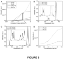
- the power-dependent properties of the as-prepared UCNP reporters was tested in respect of their emission intensities and spectrum profiles using a single nanoparticle characterization system ( Wang et al. (2016) Light Sci & Amp Appl 2018: 7, 18007 ). With increasing excitation power density, the brightness of the highly doped UCNPs increased more substantially than the lower doped UCNPs, which are not according to the invention ( Figure 6A ).
- the enhancement ratios of the emission brightness for highly Er 3+ and Tm 3+ doped UCNPs were 5 times and 12 times greater than that of lower doped UCNPs when the power exceeds 0.5 MW/cm 2 .
- the emission spectrum of highly Er 3+ doped UCNP reporters emit substantially more red at around 650 nm under higher excitation power, resulting in a bright yellowish emission.
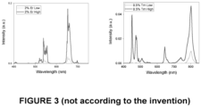
- This paint mixing effect also occurs in the highly Tm 3+ doped UCNP reporters, with appearance in purple from the phone camera (power dependent spectrum profiles of lower doped UCNP reporters are shown Figure 3 ).
- Highly Er 3+ doped UCNP reporters were compared to lower doped UCNPs by detecting different concentrations of target PSA on lateral flow strips.
- the signals from the test area and background area were recorded by a single photon counting detector.
- the signal from the highly doped UCNP reporters was much higher than the signal from the lower doped UNCPs, and the brightness enhancement ratio was consistent with the single nanoparticle characterization results.
- both reporters show the same PSA limit of detection (LOD) of 50 pg/mL. Only the highly doped UCNP reporters provide sufficient brightness for a normal phone camera.
- LOD PSA limit of detection
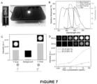
- a compact device enclosed by a 3D-printed small housing was constructed as shown in Figure 5A and Figure 7A .
- the device used a 980 nm 300 mw laser diode as the light source, two hemisphere lenses - one to focus the excitation light beam to the strip and the other for collecting the emission signal to the phone camera - and a low-cost KG-3 heat absorbing glass as the short pass filter to remove laser scattering.
- the spectral response of the phone camera CMOS (Sony IMX-214) and the transmission curve of the KG-3 glass indicates that the phone camera can read most of the visible emission signals from the highly doped UCNP reporters with only a negligible amount of excitation scattering light being detected ( Figure 7B ).
- the optics and camera setting were fixed, but the strip was moved from one side to another at a constant speed so that the average fluorescence intensity values of the testing area, the control area and the background area could be extracted from video analyses ( Figure 7C ).
- the highly doped UCNP reporters provided detectable signals when the target concentration was low, whereas the lower doped UCNPs did not.
- the LOD for PSA using highly Er 3+ doped UCNP reporters was 61 pg/mL, whereas the LOD using the lower doped UCNPs was 8.5 ng/mL.
- the LOD for EphA2 was 400 pg/mL ( Figure 8C ).
- the emission energy of highly Tm 3+ doped UCNP reporters is around 800 nm ( Figure 6C ), which is beyond the range of detection optics and phone camera ( Figure 7B ), the signal intensity is lower.
- the specificity of a two-colour LFS system was further evaluated by testing two targets, PSA and EphA2 separately, with BSA as an interfering analyte. Compared to the control groups, all of the positive groups showed much higher intensity. The results indicate that there are negligible cross-interactions.
Landscapes
- Health & Medical Sciences (AREA)
- Immunology (AREA)
- Life Sciences & Earth Sciences (AREA)
- Engineering & Computer Science (AREA)
- Chemical & Material Sciences (AREA)
- Molecular Biology (AREA)
- Hematology (AREA)
- Biomedical Technology (AREA)
- Urology & Nephrology (AREA)
- Medicinal Chemistry (AREA)
- Biotechnology (AREA)
- General Health & Medical Sciences (AREA)
- Pathology (AREA)
- Food Science & Technology (AREA)
- Physics & Mathematics (AREA)
- Analytical Chemistry (AREA)
- Biochemistry (AREA)
- Cell Biology (AREA)
- General Physics & Mathematics (AREA)
- Microbiology (AREA)
- Nanotechnology (AREA)
- Bioinformatics & Cheminformatics (AREA)
- Biophysics (AREA)
- General Engineering & Computer Science (AREA)
- Medical Informatics (AREA)
- Pharmacology & Pharmacy (AREA)
- Crystallography & Structural Chemistry (AREA)
- Investigating, Analyzing Materials By Fluorescence Or Luminescence (AREA)
- Investigating Or Analysing Materials By Optical Means (AREA)
- Investigating Or Analysing Materials By The Use Of Chemical Reactions (AREA)
Claims (12)
- Verfahren zum Bestimmen der Menge wenigstens eines Analyten in einer Probe, wobei das Verfahren Folgendes umfasst:Bereitstellen eines Querflussstreifens, der eine Einfanghälfte und eine Konjugierte, die eine Detektionshälfte enthält, die den wenigstens einen Analyten und hochgradig dotierte Aufwärtsumsetzungs-Nanopartikel binden kann, um eine Wechselwirkung des wenigstens einen Analyten mit der Einfanghälfte zu visualisieren, umfasst,Anbringen der Probe auf dem Querflussstreifen, derart, dass die Konjugierte den Analyten bindet, um einen gebundenen Analyten bereitzustellen, der anschließend durch die Einfanghälfte eingefangen wird;Bereitstellen einer Prüfvorrichtung, die eine Erregungslichtquelle, die konfiguriert ist, ein detektierbares Signal aus den hochgradig dotierten Aufwärtsumsetzungs-Nanopartikeln zu extrahieren, und einen Detektor zum Einfangen des detektierbaren Signals umfasst, wobei die Prüfvorrichtung den Querflussstreifen aufnehmen kann,Einsetzen des Querflussstreifens, auf dem die Probe angebracht worden ist, in die Prüfvorrichtung,Bestrahlen eines Bereichs des Querflussstreifens, der die hochgradig dotierten Aufwärtsumsetzungs-Nanopartikel enthält, mit einem Lichtstrahl, um dadurch ein detektierbares Signal aus den hochgradig dotierten Aufwärtsumsetzungs-Nanopartikeln zu extrahieren, undDetektieren des detektierbaren Signals und Bestimmen der Menge des wenigstens einen Analyten in der Probe basierend auf dem detektierbaren Signal,wobei die hochgradig dotierten Aufwärtsumsetzungs-Nanopartikel ein Wirtsmaterial, einen Sensibilisator, der Yb3+ ist, und einen Aktivierer, der Er3+ oder Tm3+ ist, undwobei der Sensibilisator in einer Konzentration von wenigstens 30 Mol-% vorhanden ist und der Aktivierer in einer Konzentration von wenigstens 3 Mol-% vorhanden ist.
- Verfahren nach Anspruch 1, wobei das Wirtsmaterial ein Alkalifluorid, ein Oxid oder ein Oxysulfid ist, vorzugsweise NaGdF4, Ca2F, NaYF4, LiYF4; NaLuF4, LiLuF4 KMnF3 oder Y2O3 einschließlich Kombinationen hiervon und stärker bevorzugt NaYF4.
- Verfahren nach Anspruch 1 oder Anspruch 2, wobei die hochgradig dotierten Aufwärtsumsetzungs-Nanopartikel mit einem Reaktionsträgheitsmantel passiviert sind.
- Verfahren nach einem der Ansprüche 1 bis 3, wobei die hochgradig dotierten Aufwärtsumsetzungs-Nanopartikel 8%Er/60%Yb@NaYF4, 8%Tm/60%Yb@NaYF4 oder 40%Er/60%Yb@NaYF4 sind.
- Verfahren nach einem der Ansprüche 1 bis 4, wobei die Einfanghälfte und/oder die Detektionshälfte eines oder mehrere des Folgenden enthalten: einen Antikörper, ein Aptamer, ein Epitop, eine Nukleinsäure oder ein molekulares gedrucktes Polymer.
- Verfahren nach einem der Ansprüche 1 bis 5, wobei die Prüfvorrichtung ferner eine Linse oder eine Linsenanordnung umfasst, die zwischen die Erregungslichtquelle und den Querflussstreifen eingefügt ist, um den Lichtstrahl auf den Querflussstreifen zu fokussieren, oder wobei die Prüfvorrichtung ferner eine Linse oder eine Linsenanordnung umfasst, die zwischen den Querflussstreifen und den Detektor eingefügt ist, um das Signal auf den Detektor zu fokussieren.
- Verfahren nach einem der Ansprüche 1 bis 6, wobei der Detektor eine Kamera oder ein Einzelelement-Detektor und vorzugsweise eine Smartphone-Kamera ist.
- Verfahren nach einem der Ansprüche 1 bis 7, wobei das detektierbare Signal sichtbares Licht oder Infrarotlicht ist und die Erregungslichtquelle eine Laserdiode oder eine Lichtquelle für nahes Infrarot ist.
- Verfahren nach einem der Ansprüche 1 bis 8, wobei der Lichtstrahl eine Leistung von wenigstens etwa 0,001 MW/cm2 hat.
- Verfahren nach einem der Ansprüche 1 bis 9, wobei der bestrahlte Bereich eine Fläche im Bereich von etwa 1 µm2 bis etwa 107 µm2 hat.
- Verfahren nach einem der Ansprüche 1 bis 10, wobei die Probe eine biologische Probe, vorzugsweise eine Körperflüssigkeit, ist.
- Verfahren nach einem der Ansprüche 1 bis 11, wobei die Menge des wenigstens einen Analyten in der Probe durch Anpassen der Intensität eines durch den Detektor aufgenommenen Bildes an eine im Voraus eingestellte Intensitäts-/Konzentrations-Kurve für den Analyten bestimmt werden kann.
Applications Claiming Priority (2)
| Application Number | Priority Date | Filing Date | Title |
|---|---|---|---|
| AU2018903614A AU2018903614A0 (en) | 2018-09-25 | Analyte quantitation | |
| PCT/AU2019/051034 WO2020061632A1 (en) | 2018-09-25 | 2019-09-25 | Analyte quantitation |
Publications (4)
| Publication Number | Publication Date |
|---|---|
| EP3857231A1 EP3857231A1 (de) | 2021-08-04 |
| EP3857231A4 EP3857231A4 (de) | 2022-07-06 |
| EP3857231C0 EP3857231C0 (de) | 2024-07-17 |
| EP3857231B1 true EP3857231B1 (de) | 2024-07-17 |
Family
ID=69949180
Family Applications (1)
| Application Number | Title | Priority Date | Filing Date |
|---|---|---|---|
| EP19866629.9A Active EP3857231B1 (de) | 2018-09-25 | 2019-09-25 | Analytquantifizierung |
Country Status (9)
| Country | Link |
|---|---|
| US (2) | US12228570B2 (de) |
| EP (1) | EP3857231B1 (de) |
| JP (1) | JP7462615B2 (de) |
| CN (1) | CN113056674A (de) |
| AU (1) | AU2019348048B2 (de) |
| BR (1) | BR112021005771A2 (de) |
| ES (1) | ES2992503T3 (de) |
| SG (1) | SG11202102505RA (de) |
| WO (1) | WO2020061632A1 (de) |
Families Citing this family (5)
| Publication number | Priority date | Publication date | Assignee | Title |
|---|---|---|---|---|
| GB202019772D0 (en) * | 2020-12-15 | 2021-01-27 | Ams Int Ag | Optical module |
| CN115248310B (zh) * | 2022-05-25 | 2023-08-15 | 重庆云芯医联科技有限公司 | 基于Janus铂纳米马达的免疫层析检测方法及应用 |
| US12564835B2 (en) | 2022-08-31 | 2026-03-03 | Jimei University | Biosensing platform for in-situ sampling and target detection based on upconversion luminescence |
| CN115326768B (zh) * | 2022-08-31 | 2025-08-15 | 集美大学 | 一种基于上转换发光的原位取样和靶标检测的生物传感平台 |
| JPWO2024247900A1 (de) | 2023-05-31 | 2024-12-05 |
Family Cites Families (17)
| Publication number | Priority date | Publication date | Assignee | Title |
|---|---|---|---|---|
| AU2002951465A0 (en) * | 2002-09-18 | 2002-10-03 | Poly Optics Australia Pty Ltd | Light emitting device |
| CN101788559A (zh) * | 2004-04-23 | 2010-07-28 | 中国人民解放军军事医学科学院微生物流行病研究所 | 基于上转换发光技术免疫层析试纸条 |
| GB2424946A (en) | 2005-04-05 | 2006-10-11 | Stratec Biomedical Systems Ag | A detection system for substance binding using up-converting fluorescent probes |
| CN101551388A (zh) * | 2009-05-22 | 2009-10-07 | 上海师范大学 | 一种基于上转换发光技术定量检测afp的免疫层析试纸 |
| US20130115295A1 (en) * | 2009-11-22 | 2013-05-09 | Qiang Wang | Rare Earth-Doped Up-Conversion Nanoparticles for Therapeutic and Diagnostic Applications |
| CN102199428B (zh) * | 2011-04-11 | 2013-07-10 | 复旦大学 | 基于稀土掺杂的上转换纳米晶体的荧光编码微球及其制备方法 |
| AU2013277946B2 (en) * | 2012-06-22 | 2018-07-12 | Macquarie University | Multiplex suspension assay/array using lifetime coding |
| EP2895918A4 (de) * | 2012-09-17 | 2016-04-20 | Univ Macquarie | Verbesserte aufwärtsumsetzungs-lumineszenz in seltenerddotierten teilchen |
| CN103788952A (zh) * | 2014-01-24 | 2014-05-14 | 中国科学院长春光学精密机械与物理研究所 | 高掺杂宽带激发稀土上转换荧光纳米材料及其制备方法 |
| JP6417725B2 (ja) | 2014-06-06 | 2018-11-07 | 凸版印刷株式会社 | 分析対象物の検出方法 |
| CN104374909A (zh) * | 2014-11-17 | 2015-02-25 | 北京工业大学 | 基于上转换发光技术和免疫层析技术对氯霉素定量检测方法 |
| AU2016252771B2 (en) * | 2015-04-22 | 2021-12-16 | Immunomedics, Inc. | Isolation, detection, diagnosis and/or characterization of circulating Trop-2-positive cancer cells |
| CN105842464B (zh) | 2016-06-12 | 2017-10-03 | 吉林大学 | 基于上转换发光技术的联合定量检测uNGAL和uCr的装置及其制备方法 |
| CN107525937A (zh) | 2017-08-25 | 2017-12-29 | 苏州优函信息科技有限公司 | 基于上转换发光标记物、蛋白芯片及检测方法 |
| CN107632156A (zh) * | 2017-09-14 | 2018-01-26 | 湖南大学 | 检测大肠杆菌o157:h7的上转换‑免疫层析试纸条及检测方法 |
| CN108196044B (zh) | 2017-12-27 | 2021-08-13 | 西安交通大学 | 一种基于上转换荧光适配体的侧流试纸检测方法 |
| CN108414508B (zh) * | 2018-01-16 | 2020-08-04 | 华东师范大学 | 一种光学纳米试剂盒及其应用 |
-
2019
- 2019-09-25 ES ES19866629T patent/ES2992503T3/es active Active
- 2019-09-25 SG SG11202102505RA patent/SG11202102505RA/en unknown
- 2019-09-25 WO PCT/AU2019/051034 patent/WO2020061632A1/en not_active Ceased
- 2019-09-25 AU AU2019348048A patent/AU2019348048B2/en active Active
- 2019-09-25 US US17/279,576 patent/US12228570B2/en active Active
- 2019-09-25 CN CN201980069813.7A patent/CN113056674A/zh active Pending
- 2019-09-25 JP JP2021516411A patent/JP7462615B2/ja active Active
- 2019-09-25 BR BR112021005771-4A patent/BR112021005771A2/pt unknown
- 2019-09-25 EP EP19866629.9A patent/EP3857231B1/de active Active
-
2025
- 2025-02-13 US US19/052,480 patent/US20250180552A1/en active Pending
Also Published As
| Publication number | Publication date |
|---|---|
| EP3857231A4 (de) | 2022-07-06 |
| CN113056674A (zh) | 2021-06-29 |
| US20250180552A1 (en) | 2025-06-05 |
| EP3857231C0 (de) | 2024-07-17 |
| JP2022502637A (ja) | 2022-01-11 |
| ES2992503T3 (es) | 2024-12-13 |
| US20210396746A1 (en) | 2021-12-23 |
| WO2020061632A1 (en) | 2020-04-02 |
| US12228570B2 (en) | 2025-02-18 |
| SG11202102505RA (en) | 2021-04-29 |
| AU2019348048A1 (en) | 2021-04-08 |
| AU2019348048B2 (en) | 2025-10-30 |
| JP7462615B2 (ja) | 2024-04-05 |
| BR112021005771A2 (pt) | 2021-06-29 |
| EP3857231A1 (de) | 2021-08-04 |
Similar Documents
| Publication | Publication Date | Title |
|---|---|---|
| EP3857231B1 (de) | Analytquantifizierung | |
| Gorris et al. | Perspectives and challenges of photon-upconversion nanoparticles-Part II: bioanalytical applications | |
| Goryacheva et al. | Nanosized labels for rapid immunotests | |
| Di Nardo et al. | A fluorescent immunochromatographic strip test using Quantum Dots for fumonisins detection | |
| JP4716337B2 (ja) | フローサイトメトリーによる細胞の検出・分取システム、及び検出・分取方法 | |
| CN108872163B (zh) | 一种基于近红外激发和发射的血清标记物发光检测的侧流试纸条及其制备和使用方法 | |
| Sedlmeier et al. | Highly sensitive laser scanning of photon-upconverting nanoparticles on a macroscopic scale | |
| Fan et al. | One-component dual-readout aggregation-induced emission nanobeads for qualitative and quantitative detection of C-reactive protein at the point of care | |
| Li et al. | NIR-II emitting rare-earth nanoparticles for a lateral flow immunoassay in hemolysis | |
| Hu et al. | Comparison of immunochromatographic strips using colloidal gold, quantum dots, and upconversion nanoparticles for visual detection of norfloxacin in milk samples | |
| Jin et al. | Regulation of probe density on upconversion nanoparticles enabling high-performance lateral flow assays | |
| JP5772612B2 (ja) | 表面プラズモン励起増強蛍光分光法を利用する蛍光測定装置用センサチップを用いたアッセイ方法、およびアッセイ用キット | |
| CN111735964A (zh) | 一种基于上转换荧光探针的单分子免疫检测方法 | |
| Chen et al. | Highly sensitive lanthanide-doped nanoparticles-based point-of-care diagnosis of human cardiac troponin I | |
| Li et al. | Long-term stable Eu2O3-loaded dendritic mesoporous silica nanoprobes with coordination-enhanced photoluminescence for ultrasensitive lateral flow immunoassay | |
| Gao et al. | Functional green-emitting Mn2+-doped zinc germanate persistent luminescent nanoparticles for dual-mode immunochromatographic detection | |
| Chen et al. | Upconversion nanoparticle‐assisted single‐molecule assay for detecting circulating antigens of aggressive prostate cancer | |
| Song et al. | An Ultrabright Lanthanide-Doped Luminescent Nanotag for a Smartphone-Based Visual and Portable Lateral Flow Immunoassay of Procalcitonin and Rapid Diagnosis of Bacterial Infection | |
| US20190324027A1 (en) | Enhanced infrared ray absorbing/emitting nanoparticles and on-site diagnosis kit using same | |
| US20240118198A1 (en) | Near infrared-ii region fluorescent rare earth nanoprobe test strip and its preparation method | |
| US20210364436A1 (en) | Immunostaining method, immunostaining system, and immunostaining kit | |
| Goryacheva | Contemporary trends in the development of immunochemical methods for medical analysis | |
| Bhuckory | Quantum dots and upconverting nanoparticles: Bioconjugation and time-resolved multiplexed FRET spectroscopy for cancer diagnostics | |
| US12553888B2 (en) | Fabrication of fluorescent nanoparticles and their conjugates for in vitro and in vivo diagnostics | |
| Chen et al. | Persistent Luminescence Nanoparticle-Based Biosensors |
Legal Events
| Date | Code | Title | Description |
|---|---|---|---|
| STAA | Information on the status of an ep patent application or granted ep patent |
Free format text: STATUS: THE INTERNATIONAL PUBLICATION HAS BEEN MADE |
|
| PUAI | Public reference made under article 153(3) epc to a published international application that has entered the european phase |
Free format text: ORIGINAL CODE: 0009012 |
|
| STAA | Information on the status of an ep patent application or granted ep patent |
Free format text: STATUS: REQUEST FOR EXAMINATION WAS MADE |
|
| 17P | Request for examination filed |
Effective date: 20210322 |
|
| AK | Designated contracting states |
Kind code of ref document: A1 Designated state(s): AL AT BE BG CH CY CZ DE DK EE ES FI FR GB GR HR HU IE IS IT LI LT LU LV MC MK MT NL NO PL PT RO RS SE SI SK SM TR |
|
| DAV | Request for validation of the european patent (deleted) | ||
| DAX | Request for extension of the european patent (deleted) | ||
| A4 | Supplementary search report drawn up and despatched |
Effective date: 20220603 |
|
| RIC1 | Information provided on ipc code assigned before grant |
Ipc: G01N 33/543 20060101ALI20220530BHEP Ipc: G01N 33/53 20060101ALI20220530BHEP Ipc: G01N 33/58 20060101ALI20220530BHEP Ipc: G01N 33/574 20060101AFI20220530BHEP |
|
| STAA | Information on the status of an ep patent application or granted ep patent |
Free format text: STATUS: EXAMINATION IS IN PROGRESS |
|
| 17Q | First examination report despatched |
Effective date: 20230412 |
|
| GRAP | Despatch of communication of intention to grant a patent |
Free format text: ORIGINAL CODE: EPIDOSNIGR1 |
|
| STAA | Information on the status of an ep patent application or granted ep patent |
Free format text: STATUS: GRANT OF PATENT IS INTENDED |
|
| INTG | Intention to grant announced |
Effective date: 20240212 |
|
| GRAS | Grant fee paid |
Free format text: ORIGINAL CODE: EPIDOSNIGR3 |
|
| GRAA | (expected) grant |
Free format text: ORIGINAL CODE: 0009210 |
|
| STAA | Information on the status of an ep patent application or granted ep patent |
Free format text: STATUS: THE PATENT HAS BEEN GRANTED |
|
| AK | Designated contracting states |
Kind code of ref document: B1 Designated state(s): AL AT BE BG CH CY CZ DE DK EE ES FI FR GB GR HR HU IE IS IT LI LT LU LV MC MK MT NL NO PL PT RO RS SE SI SK SM TR |
|
| REG | Reference to a national code |
Ref country code: CH Ref legal event code: EP |
|
| REG | Reference to a national code |
Ref country code: DE Ref legal event code: R096 Ref document number: 602019055501 Country of ref document: DE |
|
| REG | Reference to a national code |
Ref country code: IE Ref legal event code: FG4D |
|
| U01 | Request for unitary effect filed |
Effective date: 20240809 |
|
| U07 | Unitary effect registered |
Designated state(s): AT BE BG DE DK EE FI FR IT LT LU LV MT NL PT RO SE SI Effective date: 20240902 |
|
| U20 | Renewal fee for the european patent with unitary effect paid |
Year of fee payment: 6 Effective date: 20241008 |
|
| REG | Reference to a national code |
Ref country code: ES Ref legal event code: FG2A Ref document number: 2992503 Country of ref document: ES Kind code of ref document: T3 Effective date: 20241213 |
|
| PG25 | Lapsed in a contracting state [announced via postgrant information from national office to epo] |
Ref country code: NO Free format text: LAPSE BECAUSE OF FAILURE TO SUBMIT A TRANSLATION OF THE DESCRIPTION OR TO PAY THE FEE WITHIN THE PRESCRIBED TIME-LIMIT Effective date: 20241017 |
|
| PG25 | Lapsed in a contracting state [announced via postgrant information from national office to epo] |
Ref country code: GR Free format text: LAPSE BECAUSE OF FAILURE TO SUBMIT A TRANSLATION OF THE DESCRIPTION OR TO PAY THE FEE WITHIN THE PRESCRIBED TIME-LIMIT Effective date: 20241018 Ref country code: PL Free format text: LAPSE BECAUSE OF FAILURE TO SUBMIT A TRANSLATION OF THE DESCRIPTION OR TO PAY THE FEE WITHIN THE PRESCRIBED TIME-LIMIT Effective date: 20240717 |
|
| PG25 | Lapsed in a contracting state [announced via postgrant information from national office to epo] |
Ref country code: IS Free format text: LAPSE BECAUSE OF FAILURE TO SUBMIT A TRANSLATION OF THE DESCRIPTION OR TO PAY THE FEE WITHIN THE PRESCRIBED TIME-LIMIT Effective date: 20241117 |
|
| PG25 | Lapsed in a contracting state [announced via postgrant information from national office to epo] |
Ref country code: HR Free format text: LAPSE BECAUSE OF FAILURE TO SUBMIT A TRANSLATION OF THE DESCRIPTION OR TO PAY THE FEE WITHIN THE PRESCRIBED TIME-LIMIT Effective date: 20240717 |
|
| PG25 | Lapsed in a contracting state [announced via postgrant information from national office to epo] |
Ref country code: RS Free format text: LAPSE BECAUSE OF FAILURE TO SUBMIT A TRANSLATION OF THE DESCRIPTION OR TO PAY THE FEE WITHIN THE PRESCRIBED TIME-LIMIT Effective date: 20241017 |
|
| PG25 | Lapsed in a contracting state [announced via postgrant information from national office to epo] |
Ref country code: RS Free format text: LAPSE BECAUSE OF FAILURE TO SUBMIT A TRANSLATION OF THE DESCRIPTION OR TO PAY THE FEE WITHIN THE PRESCRIBED TIME-LIMIT Effective date: 20241017 Ref country code: PL Free format text: LAPSE BECAUSE OF FAILURE TO SUBMIT A TRANSLATION OF THE DESCRIPTION OR TO PAY THE FEE WITHIN THE PRESCRIBED TIME-LIMIT Effective date: 20240717 Ref country code: NO Free format text: LAPSE BECAUSE OF FAILURE TO SUBMIT A TRANSLATION OF THE DESCRIPTION OR TO PAY THE FEE WITHIN THE PRESCRIBED TIME-LIMIT Effective date: 20241017 Ref country code: IS Free format text: LAPSE BECAUSE OF FAILURE TO SUBMIT A TRANSLATION OF THE DESCRIPTION OR TO PAY THE FEE WITHIN THE PRESCRIBED TIME-LIMIT Effective date: 20241117 Ref country code: HR Free format text: LAPSE BECAUSE OF FAILURE TO SUBMIT A TRANSLATION OF THE DESCRIPTION OR TO PAY THE FEE WITHIN THE PRESCRIBED TIME-LIMIT Effective date: 20240717 Ref country code: GR Free format text: LAPSE BECAUSE OF FAILURE TO SUBMIT A TRANSLATION OF THE DESCRIPTION OR TO PAY THE FEE WITHIN THE PRESCRIBED TIME-LIMIT Effective date: 20241018 |
|
| PG25 | Lapsed in a contracting state [announced via postgrant information from national office to epo] |
Ref country code: SM Free format text: LAPSE BECAUSE OF FAILURE TO SUBMIT A TRANSLATION OF THE DESCRIPTION OR TO PAY THE FEE WITHIN THE PRESCRIBED TIME-LIMIT Effective date: 20240717 |
|
| PG25 | Lapsed in a contracting state [announced via postgrant information from national office to epo] |
Ref country code: MC Free format text: LAPSE BECAUSE OF FAILURE TO SUBMIT A TRANSLATION OF THE DESCRIPTION OR TO PAY THE FEE WITHIN THE PRESCRIBED TIME-LIMIT Effective date: 20240717 |
|
| PG25 | Lapsed in a contracting state [announced via postgrant information from national office to epo] |
Ref country code: CZ Free format text: LAPSE BECAUSE OF FAILURE TO SUBMIT A TRANSLATION OF THE DESCRIPTION OR TO PAY THE FEE WITHIN THE PRESCRIBED TIME-LIMIT Effective date: 20240717 |
|
| PG25 | Lapsed in a contracting state [announced via postgrant information from national office to epo] |
Ref country code: SK Free format text: LAPSE BECAUSE OF FAILURE TO SUBMIT A TRANSLATION OF THE DESCRIPTION OR TO PAY THE FEE WITHIN THE PRESCRIBED TIME-LIMIT Effective date: 20240717 |
|
| REG | Reference to a national code |
Ref country code: CH Ref legal event code: PL |
|
| PLBE | No opposition filed within time limit |
Free format text: ORIGINAL CODE: 0009261 |
|
| STAA | Information on the status of an ep patent application or granted ep patent |
Free format text: STATUS: NO OPPOSITION FILED WITHIN TIME LIMIT |
|
| 26N | No opposition filed |
Effective date: 20250422 |
|
| PG25 | Lapsed in a contracting state [announced via postgrant information from national office to epo] |
Ref country code: CH Free format text: LAPSE BECAUSE OF NON-PAYMENT OF DUE FEES Effective date: 20240930 |
|
| PG25 | Lapsed in a contracting state [announced via postgrant information from national office to epo] |
Ref country code: IE Free format text: LAPSE BECAUSE OF NON-PAYMENT OF DUE FEES Effective date: 20240925 |
|
| PGFP | Annual fee paid to national office [announced via postgrant information from national office to epo] |
Ref country code: GB Payment date: 20250918 Year of fee payment: 7 |
|
| U20 | Renewal fee for the european patent with unitary effect paid |
Year of fee payment: 7 Effective date: 20250929 |
|
| PG25 | Lapsed in a contracting state [announced via postgrant information from national office to epo] |
Ref country code: CY Free format text: LAPSE BECAUSE OF FAILURE TO SUBMIT A TRANSLATION OF THE DESCRIPTION OR TO PAY THE FEE WITHIN THE PRESCRIBED TIME-LIMIT; INVALID AB INITIO Effective date: 20190925 |
|
| PGFP | Annual fee paid to national office [announced via postgrant information from national office to epo] |
Ref country code: ES Payment date: 20251020 Year of fee payment: 7 |
|
| PG25 | Lapsed in a contracting state [announced via postgrant information from national office to epo] |
Ref country code: HU Free format text: LAPSE BECAUSE OF FAILURE TO SUBMIT A TRANSLATION OF THE DESCRIPTION OR TO PAY THE FEE WITHIN THE PRESCRIBED TIME-LIMIT; INVALID AB INITIO Effective date: 20190925 |