EP3857537B1 - Techniques d'affichage incorporant actionneurs fluidiques et systèmes et procédés associés - Google Patents
Techniques d'affichage incorporant actionneurs fluidiques et systèmes et procédés associés Download PDFInfo
- Publication number
- EP3857537B1 EP3857537B1 EP19805462.9A EP19805462A EP3857537B1 EP 3857537 B1 EP3857537 B1 EP 3857537B1 EP 19805462 A EP19805462 A EP 19805462A EP 3857537 B1 EP3857537 B1 EP 3857537B1
- Authority
- EP
- European Patent Office
- Prior art keywords
- display
- fluid
- cavity
- fluidic
- actuator
- Prior art date
- Legal status (The legal status is an assumption and is not a legal conclusion. Google has not performed a legal analysis and makes no representation as to the accuracy of the status listed.)
- Not-in-force
Links
Images






Classifications
-
- G—PHYSICS
- G09—EDUCATION; CRYPTOGRAPHY; DISPLAY; ADVERTISING; SEALS
- G09G—ARRANGEMENTS OR CIRCUITS FOR CONTROL OF INDICATING DEVICES USING STATIC MEANS TO PRESENT VARIABLE INFORMATION
- G09G3/00—Control arrangements or circuits, of interest only in connection with visual indicators other than cathode-ray tubes
- G09G3/20—Control arrangements or circuits, of interest only in connection with visual indicators other than cathode-ray tubes for presentation of an assembly of a number of characters, e.g. a page, by composing the assembly by combination of individual elements arranged in a matrix no fixed position being assigned to or needed to be assigned to the individual characters or partial characters
- G09G3/34—Control arrangements or circuits, of interest only in connection with visual indicators other than cathode-ray tubes for presentation of an assembly of a number of characters, e.g. a page, by composing the assembly by combination of individual elements arranged in a matrix no fixed position being assigned to or needed to be assigned to the individual characters or partial characters by control of light from an independent source
- G09G3/3433—Control arrangements or circuits, of interest only in connection with visual indicators other than cathode-ray tubes for presentation of an assembly of a number of characters, e.g. a page, by composing the assembly by combination of individual elements arranged in a matrix no fixed position being assigned to or needed to be assigned to the individual characters or partial characters by control of light from an independent source using light modulating elements actuated by an electric field and being other than liquid crystal devices and electrochromic devices
-
- G—PHYSICS
- G02—OPTICS
- G02B—OPTICAL ELEMENTS, SYSTEMS OR APPARATUS
- G02B26/00—Optical devices or arrangements for the control of light using movable or deformable optical elements
- G02B26/004—Optical devices or arrangements for the control of light using movable or deformable optical elements based on a displacement or a deformation of a fluid
-
- G—PHYSICS
- G09—EDUCATION; CRYPTOGRAPHY; DISPLAY; ADVERTISING; SEALS
- G09G—ARRANGEMENTS OR CIRCUITS FOR CONTROL OF INDICATING DEVICES USING STATIC MEANS TO PRESENT VARIABLE INFORMATION
- G09G2300/00—Aspects of the constitution of display devices
- G09G2300/06—Passive matrix structure, i.e. with direct application of both column and row voltages to the light emitting or modulating elements, other than LCD or OLED
-
- G—PHYSICS
- G09—EDUCATION; CRYPTOGRAPHY; DISPLAY; ADVERTISING; SEALS
- G09G—ARRANGEMENTS OR CIRCUITS FOR CONTROL OF INDICATING DEVICES USING STATIC MEANS TO PRESENT VARIABLE INFORMATION
- G09G2310/00—Command of the display device
- G09G2310/02—Addressing, scanning or driving the display screen or processing steps related thereto
- G09G2310/0243—Details of the generation of driving signals
- G09G2310/0254—Control of polarity reversal in general, other than for liquid crystal displays
- G09G2310/0256—Control of polarity reversal in general, other than for liquid crystal displays with the purpose of reversing the voltage across a light emitting or modulating element within a pixel
-
- G—PHYSICS
- G09—EDUCATION; CRYPTOGRAPHY; DISPLAY; ADVERTISING; SEALS
- G09G—ARRANGEMENTS OR CIRCUITS FOR CONTROL OF INDICATING DEVICES USING STATIC MEANS TO PRESENT VARIABLE INFORMATION
- G09G2354/00—Aspects of interface with display user
-
- G—PHYSICS
- G09—EDUCATION; CRYPTOGRAPHY; DISPLAY; ADVERTISING; SEALS
- G09G—ARRANGEMENTS OR CIRCUITS FOR CONTROL OF INDICATING DEVICES USING STATIC MEANS TO PRESENT VARIABLE INFORMATION
- G09G3/00—Control arrangements or circuits, of interest only in connection with visual indicators other than cathode-ray tubes
- G09G3/20—Control arrangements or circuits, of interest only in connection with visual indicators other than cathode-ray tubes for presentation of an assembly of a number of characters, e.g. a page, by composing the assembly by combination of individual elements arranged in a matrix no fixed position being assigned to or needed to be assigned to the individual characters or partial characters
- G09G3/34—Control arrangements or circuits, of interest only in connection with visual indicators other than cathode-ray tubes for presentation of an assembly of a number of characters, e.g. a page, by composing the assembly by combination of individual elements arranged in a matrix no fixed position being assigned to or needed to be assigned to the individual characters or partial characters by control of light from an independent source
- G09G3/3433—Control arrangements or circuits, of interest only in connection with visual indicators other than cathode-ray tubes for presentation of an assembly of a number of characters, e.g. a page, by composing the assembly by combination of individual elements arranged in a matrix no fixed position being assigned to or needed to be assigned to the individual characters or partial characters by control of light from an independent source using light modulating elements actuated by an electric field and being other than liquid crystal devices and electrochromic devices
- G09G3/344—Control arrangements or circuits, of interest only in connection with visual indicators other than cathode-ray tubes for presentation of an assembly of a number of characters, e.g. a page, by composing the assembly by combination of individual elements arranged in a matrix no fixed position being assigned to or needed to be assigned to the individual characters or partial characters by control of light from an independent source using light modulating elements actuated by an electric field and being other than liquid crystal devices and electrochromic devices based on particles moving in a fluid or in a gas, e.g. electrophoretic devices
-
- H—ELECTRICITY
- H02—GENERATION; CONVERSION OR DISTRIBUTION OF ELECTRIC POWER
- H02N—ELECTRIC MACHINES NOT OTHERWISE PROVIDED FOR
- H02N1/00—Electrostatic generators or motors using a solid moving electrostatic charge carrier
- H02N1/002—Electrostatic motors
Definitions
- the present disclosure generally relates to displays and methods of making and uses thereof.
- Displays such as emissive LED displays, can consume a substantial amount of electrical power when the display is active.
- Large area displays such as billboards and other digital signs, can consume an amount of electrical power equivalent to that consumed by multiple average-size households during peak hours. This high-power consumption results not only in high operating costs but also additional challenges associated with high power demands.
- a reliable power source is often necessary for proper and continuous operation of a display, which can limit deployment of high-power consumption displays to locations where such power sources are available.
- high power consumption typically generates a substantial amount of heat, and active cooling can be required to maintain the health of the display and its electronics. Active cooling can in turn lead to additional cost, power consumption, and maintenance.
- display devices and components thereof are provided that overcome one or more of the aforementioned deficiencies.
- the invention is set forth in claim 1 that follows.
- a display device configured to alter an optical property by moving an amount of a first fluid through which external light can pass, the display device including a fluidic display unit having at least a first cavity containing a first fluid, the first fluid movable within the first cavity by varying an amount of pressure on the first cavity; and a fluidic actuator mechanically coupled to the fluid-filled cavity of the fluidic display unit, the fluidic actuator having a second fluid, wherein the fluidic actuator is configured to be electrically actuated to vary the amount of pressure on the first cavity of the fluidic display unit, wherein varying the pressure causes movement of the first fluid within the fluidic display unit, thereby altering the optical property of the display.
- display devices have as a component an actuator.
- the actuator has a first cavity containing fluid and bounded at least in part by a first elastomer; a second cavity containing fluid and bounded at least in by part by a second elastomer; a channel connecting the first cavity to the second cavity and through which fluid can flow; and a valve configured to be electrically operated into an open state or a closed state and thereby allow or block flow of the fluid through the channel, respectively, wherein maintaining the valve in the closed state requires less electrical power than maintaining the valve in the open state.
- a display device configured to alter an optical property by moving an amount of a first fluid through which external light can pass, the display device comprising: a fluidic display unit comprising at least a first cavity comprising a first fluid, the first fluid movable within the first cavity by varying an amount of pressure on the first cavity; and a means of electrically varying the amount of pressure on the first cavity of the fluidic display unit, wherein varying the pressure causes movement of the first fluid within the fluidic display unit, thereby altering the optical property of the display.
- Some reflective display technologies utilize a colored fluid, such as an ink, which is configured to be moved between a reflector and a viewer of the display.
- US 2014/355101 describes such a device and display using liquid ink and elastomers. By moving fluid around within the display device, an amount of color between the viewer and the reflector can be changed, thereby changing an amount of color visible to the viewer.
- Such displays typically require energy to maintain the fluid in a particular state, however.
- some fluidic devices move fluid between cavities through channels or flow paths using an external energy source that moves the fluid from a low energy state to a high energy state. If the energy source is removed, however, the fluid will return to its low energy state.
- Conventional mechanisms to stop fluid flow such as check valves cannot generally be used to mitigate this issue because it is necessary to allow fluid to flow reversibly along the same channel or flow path.
- display technologies and methods of making and uses thereof are provided.
- the display technologies can overcome one or more of the aforementioned deficiencies.
- display technologies are provided based on fluidic actuators.
- passive displays are provided that overcome one or more of the aforementioned deficiencies.
- Passive displays also called reflective displays, can use external ambient light as a light source and therefore can be capable of utilizing less power compared to the internal bulbs or LEDs of emissive displays.
- multistable displays are provided arranged so that one or more pixels can maintain a state without being actively controlled, which allows the pixels to consume little or no power while maintaining that state. Passive, multistable displays therefore represent an advantageous type of low-power display in which no internal light source is necessary and the primary use of power is in writing new information to a pixel of the display.
- This disclosure provides techniques for producing a fluidic actuator in which fluid can be moved then maintained in a desired arrangement.
- the actuator can produce a pressure at a surface of the actuator that is capable of being adjusted and, once adjusted to a desired amount, held at that pressure using little to no power.
- the actuator can be operated to push against a surface of the fluidic display unit with a varying amount of pressure, thereby providing a level of control over the location of fluid within the fluidic display unit.
- the disclosure also embodies a method, of which an example has been provided.
- the acts performed as part of the method can be ordered in any suitable way. Accordingly, aspects can be constructed in which acts are performed in an order different than illustrated, which can include performing some acts simultaneously, even though shown as sequential acts in illustrative aspects.
- ratios, concentrations, amounts, and other numerical data can be expressed herein in a range format. It is to be understood that such a range format is used for convenience and brevity, and thus, should be interpreted in a flexible manner to include not only the numerical values explicitly recited as the limits of the range, but also to include all the individual numerical values or sub-ranges encompassed within that range as if each numerical value and sub-range is explicitly recited.
- a numerical range of "about 0.1% to about 5%” should be interpreted to include not only the explicitly recited values of about 0.1% to about 5%, but also include individual values (e.g., 1%, 2%, 3%, and 4%) and the sub-ranges (e.g., 0.5%, 1.1%, 2.2%, 3.3%, and 4.4%) within the indicated range.
- the stated range includes one or both of the limits
- ranges excluding either or both of those included limits are also included in the disclosure, e.g. the phrase "x to y" includes the range from 'x' to 'y' as well as the range greater than 'x' and less than 'y'.
- the range can also be expressed as an upper limit, e.g.
- 'about x, y, z, or less' should be interpreted to include the specific ranges of 'about x', 'about y', and 'about z' as well as the ranges of 'less than x', less than y', and 'less than z'.
- the phrase 'about x, y, z, or greater' should be interpreted to include the specific ranges of 'about x', 'about y', and 'about z' as well as the ranges of 'greater than x', greater than y', and 'greater than z'.
- the term "about” can include traditional rounding according to significant figures of the numerical value.
- the phrase "about 'x' to 'y′′′, where 'x' and 'y' are numerical values includes "about 'x' to about 'y′′′.
- units may be used herein that are non-metric or non-SI units. Such units may be, for instance, in U.S. Customary Measures, e.g., as set forth by the National Institute of Standards and Technology, Department of Commerce, United States of America in publications such as NIST HB 44, NIST HB 133, NIST SP 811, NIST SP 1038, NBS Miscellaneous Publication 214, and the like. The units in U.S.
- Customary Measures are understood to include equivalent dimensions in metric and other units (e.g., a dimension disclosed as “1 inch” is intended to mean an equivalent dimension of "2.5 cm”; a unit disclosed as “1 pcf” is intended to mean an equivalent dimension of 0.157 kN/m 3 ; or a unit disclosed 100°F is intended to mean an equivalent dimension of 37.8°C; and the like) as understood by a person of ordinary skill in the art.
- actions are described as taken by a "user.” It should be appreciated that a "user” need not be a single individual, and that in some aspects, actions attributable to a "user” can be performed by a team of individuals and/or an individual in combination with computerassisted tools or other mechanisms.
- Passive, multistable displays based on microfluidic actuators present a unique solution to the above-described challenges.
- Passive displays also called reflective displays, use external ambient light as a light source and therefore can utilize less power compared to the internal bulbs or LEDs of emissive displays.
- some multistable displays are arranged so that a pixel can maintain its state without being actively controlled, which allows the pixel to consume little or no power while it maintains the state.
- Passive, multistable displays therefore represent a potentially advantageous type of low-power display in which no internal light source is necessary and the primary use of power is in writing new information to a pixel of the display.
- the applicants have recognized and appreciated techniques for producing a fluidic actuator in which fluid can be moved then maintained in a desired arrangement.
- the actuator can produce a pressure at a surface of the actuator that can be adjusted and, once adjusted to a desired amount, held at that pressure using little to no power.
- the actuator By mechanically coupling a fluidic display unit to such a surface, the actuator can be operated to push against a surface of the fluidic display unit with a varying amount of pressure, thereby providing a level of control over the movement and location of fluid within the fluidic display unit.
- FIG. 1 is a block diagram of an illustrative display device comprising a fluidic actuator.
- display device 100 includes a fluidic display unit 110 and a fluidic actuator 120 arranged and configured to apply a variable force 115 to the fluidic display unit 110.
- the display device is configured to be viewed from the perspective of a viewer 101.
- a “fluidic” element such as a display unit or actuator, refers to an element that includes a fluid and whose function depends, at least in part, on the position and/or movement of said fluid.
- a fluidic element can be filled with fluid, although it is not a requirement that an element be completely filled with fluid to be considered a "fluidic" element.
- fluidic display unit 110 can include any display unit containing fluid that is configured to alter one or more optical properties of the display unit by moving the fluid within the display unit.
- the display unit 110 can represent any suitable unit of a display, such as but not limited to a pixel, a sub-pixel, or a plurality of pixels.
- Illustrative examples of optical properties that can be altered by movement of fluid within the fluidic display unit 110 include apparent color, brightness, specularity, or any other alteration in the nature and/or type of electromagnetic radiation that can be emitted and/or reflected by the display unit.
- an optical property that can be altered by movement of fluid within the fluidic display unit 110 can include alterations to changes in the color of light reflected from the display unit.
- such alterations can include alterations to changes in color produced when white light reflects from the display unit. That is, by arranging fluid within display unit 110 in a first manner, it can be that white light reflecting from the display unit 110 is emitted with a first non-white color (e.g., blue), and by arranging fluid within the display unit in a second manner, it can be that white light reflecting from the display unit is instead emitted with a second non-white color (e.g., red).
- fluidic display unit 110 can include inks, pigments and/or other color agents that can be arranged within the fluidic display unit to alter how the color of reflected light is affected by such reflection.
- an optical property that can be altered by movement of fluid within the fluidic display unit 110 can include alterations in the manner in which non-visible electromagnetic radiation, such as x-rays, radio waves, microwaves, infrared, etc. is emitted and/or reflected from the display unit.
- non-visible electromagnetic radiation such as x-rays, radio waves, microwaves, infrared, etc.
- fluidic display unit 110 can include a plurality of cavities containing a fluid, and the variable force 115 applied by the fluidic actuator 120 can cause fluid to flow between the cavities.
- variable force 115 is maintained at a fixed, or substantially fixed, magnitude, net fluid flow within the fluidic display unit 110 can eventually cease as the fluid in the display unit reaches an equilibrium state.
- the fluidic display unit 110 can be arranged such that an amount of fluid in one or more of the cavities is determinative of at least one optical property of the fluidic display unit, such that increasing or decreasing the amount of fluid in the one or more cavities can cause an alteration in said at least one optical property.
- fluidic display unit 110 can include one or more reflectors such that electromagnetic radiation can pass through at least a portion of the fluidic display unit, be reflected from the reflector, and be output from the display unit in a viewing direction.
- the reflector can, in some aspects, be arranged so that the electromagnetic radiation passes through some, but not all, of the cavities.
- the reflector can be configured to reflect any wavelength or wavelengths of radiation as desired; for example, where the display unit is configured to alter optical properties of visible light, the reflector can be configured to reflect visible light.
- the reflector can be configured to reflect non-visible light, either exclusively or in addition to visible light.
- a reflector can include one or more of paper (e.g., white paper), Teflon, white painted surfaces, titanium oxide particles, barium sulfate coatings, silver mirrors, indium tin oxide coatings, or combinations thereof.
- fluidic actuator 120 is arranged and configured to apply a variable force 115 to the fluidic display unit 110.
- the fluidic actuator 120 is configured to apply a mechanical force to the fluidic display unit.
- the variable force 115 can be applied directly from the fluidic actuator 120 to the fluidic display unit 110 (e.g., the actuator can be in physical contact with the display unit) and/or can be applied via intermediate mechanical elements.
- fluidic actuator 120 can include one or more membranes comprising an electroactive polymer, which can be actuated by an electric field.
- dielectric elastomers produce large strains by sandwiching a passive elastomer film between two electrodes. By applying a voltage to the electrodes, a very large strain (e.g., up to 300%) can be generated in the elastomer film. When a dielectric elastomer is fixed at one or more places, this strain can cause the film to change in shape and/or length. Consequently, the pressure of a fluid arranged within a cavity bounded by a dielectric elastomer can be altered by actuation of the elastomer.
- suitable electroactive polymers can include, but are not limited to, polyacrylate elastomer, natural rubber, silicone rubber, chloroprene rubber, butyl rubber, isoprene rubber, nitrile rubber, ethylene propylene diene monomer (EPDM), acrylonitrile butadiene styrene (ABS), fluorosilicone, thermoplastic elastomer, poly(urethane) rubber, elastomer copolymers, composites of the aforementioned polymers with at least one kind of inorganic filler, or combinations thereof, including more than one interpenetrating polymer network.
- polyacrylate elastomer natural rubber, silicone rubber, chloroprene rubber, butyl rubber, isoprene rubber, nitrile rubber, ethylene propylene diene monomer (EPDM), acrylonitrile butadiene styrene (ABS), fluorosilicone, thermoplastic elastomer, poly(urethane) rubber
- fluidic actuator 120 can include one or more valves configured to be electrically operated into a plurality of states, which include at least an open state and a closed state.
- a closed state of a valve refers to a state in which fluid flow is blocked by the valve, such that either no fluid flows through the valve, or at least that a sufficiently small amount of fluid flows through the valve that the valve can maintain fluid pressure on either side of the valve for a desired amount of time.
- An open state of a valve in contrast, refers to a state in which fluid can flow through the valve, although in some cases a valve can be configured to be operated into multiple different open states that allow fluid flow through the valve to different extents.
- operating a valve into a closed state can require less power than operating the valve into any open states.
- This configuration can be produced in various ways, including through the application of fluid pressure to maintain the closed state in the absence of electrical actuation. Examples of such approaches are discussed further below.
- fluidic actuator 120 can include one or more valves in addition to one or more membranes comprising an electroactive polymer. Such an actuator can be operated to move fluid around within the actuator by actuating the electroactive polymer as described above while the valve is in an open state, then closing the valve to maintain the fluid in desired locations. In some cases, the fluid can be maintained in desired locations even when the electroactive polymer is relaxed because, although there can be a net fluid pressure against the valve from one side of the valve, the valve is in a closed state and thereby is able to maintain this net pressure for a desired amount of time (which, in some cases, is because no fluid flows through the valve).
- fluidic actuator 120 can be arranged to have a higher fluid pressure than the fluidic display unit 110.
- fluidic actuator 120 include one or more hydraulic fluids, such as aqueous salt solutions, glycerin, glycols, polyols, silicone oils, vegetable oils, mineral oils, motor oils, lubricating oils, polyalphaolefins, ionic liquids, hydrofluoroethers, fluoroketones, silicate esters, synthetic oils, and/or fluorinated hydrocarbons.
- hydraulic fluids such as aqueous salt solutions, glycerin, glycols, polyols, silicone oils, vegetable oils, mineral oils, motor oils, lubricating oils, polyalphaolefins, ionic liquids, hydrofluoroethers, fluoroketones, silicate esters, synthetic oils, and/or fluorinated hydrocarbons.
- FIG. 2 is a cross-sectional schematic of an illustrative fluidic actuator, according to some aspects.
- Fluidic actuator 200 is provided as one possible implementation of fluidic actuator 120 shown in FIG. 1 and discussed above.
- fluidic actuator 200 includes active membrane 201 and passive membrane 212 which are coupled to a frame 208.
- Fluidic actuator 200 can be controlled to produce varying amounts of pressure at the membrane 201 as discussed below.
- the actuator 200 can apply a variable force to an element, such as a fluidic display unit, that is mechanically coupled to the membrane 201.
- the interior of the actuator bounded by the membranes 201 and 212 and the frame 208, includes a fluid 209.
- a valve 203 which includes flap 204, controls whether fluid 209 can flow between the upper cavity 217 and the lower cavity 218.
- Support 208 can include a relatively stiff material such as polyacrylate, acrylonitrile butadiene styrene (ABS), polyethylene terephthalate (PET), high-density polyethylene (HDPE), Kapton, epoxy, nylon, polyvinyl chloride (PVC), polypropylene (PP), polycarbonate, fiberglass composites, and/or carbon composites.
- ABS acrylate
- PET polyethylene terephthalate
- HDPE high-density polyethylene
- Kapton epoxy
- epoxy nylon
- PVC polyvinyl chloride
- PP polypropylene
- support 208 can be a separate part or a part of a multilayer component.
- fluid 209 can be a non-compressible fluid, such as an aqueous salt solution, glycerin, glycols, polyols, silicone oils, vegetable oils, mineral oils, motor oils, lubricating oils, polyalphaolefins, ionic liquids, hydrofluoroethers, fluoroketones, silicate esters, synthetic oils, fluorinated hydrocarbons, or combinations thereof.
- a non-compressible fluid such as an aqueous salt solution, glycerin, glycols, polyols, silicone oils, vegetable oils, mineral oils, motor oils, lubricating oils, polyalphaolefins, ionic liquids, hydrofluoroethers, fluoroketones, silicate esters, synthetic oils, fluorinated hydrocarbons, or combinations thereof.
- the valve 203 includes layers 211 and 221, a spacer layer 222, and a flap 204.
- the layers 211 and 221 can include apertures which allow fluid to flow between the cavities 217 and 218.
- the layers 211 and 221 can be patterned with channels to form apertures allowing said fluid flow.
- layers 211 and 221 can include a stiff material such as PET, polyester, glycol modified polyester, mylar, polyamide, polyimide, phenolic, polypropylene, polyacrylate or combinations thereof.
- layers 211 and 221 are laminated with an electrically conductive material electrically coupled to switch 213 and switch 216, respectively, which are in turn coupled to a power source 207 (e.g., a battery, a high-voltage DC-DC converter, a high voltage AC-DC converter, or a rectified transformer).
- a power source 207 e.g., a battery, a high-voltage DC-DC converter, a high voltage AC-DC converter, or a rectified transformer.
- These layers of electrically conductive material referred to henceforth as electrode layers, can be configured for electrostatic actuation with respect to flap 204.
- by opening and closing the switches 213 and 216 differences in electric potential between the flap 204, which is coupled to ground, and the layers 211 and/or 221 can be produced.
- the flap can include a conductive polymer, or a laminate of a polymer and/or a conductive layer, and thereby be attracted to an adjacent layer 211 or 221 when such a potential difference exists. As a result, the flap can be opened and closed with respect to aperture 210 by activation of the switches 213 and 216.
- the flap 204 can include a conductive polymer which can include, but is not limited to, doped polyaniline or rigid-rod conductive polymers, filled rubbers such as silicone rubber, polyurethane rubber, acrylic rubber containing one or more of the following fillers: carbon black, metal-coated carbon, carbon nanotubes, and/or graphene, or combinations thereof.
- flap 204 can include a laminate of dielectric polymers having an electrically-conductive layer, such as, but not limited to, mylar or polypropylene coated with aluminum, silicone rubber coated with an electrically conductive silicone elastomer composite, polyaniline coated polyethylene, and/or graphene coated polypropylene.
- an electrically-conductive layer such as, but not limited to, mylar or polypropylene coated with aluminum, silicone rubber coated with an electrically conductive silicone elastomer composite, polyaniline coated polyethylene, and/or graphene coated polypropylene.
- membranes 201 and 212 work as counter-acting springs with fluid 209 as a force or displacement transfer medium.
- Membrane 201 includes a dielectric elastomer, which in turn includes dielectric 215 sandwiched between electrodes 214A and 214B.
- the electrodes are electrostatically attracted to one another, causing the membrane 201 to expand laterally. Since the membrane 201 is fixed at boundaries, this causes the membrane to deform outwards and the pressure in cavity 216 lowers.
- the switch 219 is closed and fluid flows from cavity 218 to 217, then subsequently the valve 203 is closed by closing switch 213, when switch 219 is opened again, the higher pressure of the fluid in cavity 217 will be unable to flow back to cavity 218. Further, because the direction of flap 204 and the higher pressure in cavity 217 relative to cavity 218, the flap could be maintained at closed position when switch 219 is turned off because the fluid pressure acts to push the flap into a closed position. In this fashion, the actuation state can be maintained without supplying power for either active membrane 201 or valve 203. Furthermore, by controlling an amount of fluid that is caused to flow into cavity 217 from cavity 218 prior to closing of the valve 203, the pressure at membrane 201 can be controlled and held without supplying power to either the valve of the membrane 201.
- the relative volumes of fluid in cavity 217 and cavity 218 can be varied by any suitable combination of adjusting the voltage of voltage source 220 and/or by varying the duty cycle of electrical pulses using switch 219.
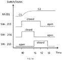
- FIGS. 3A-3B depict an illustrative sequence of actuator state change for the fluidic actuator of FIG. 2 , according to some aspects. As discussed above, higher pressures can be produced and maintained in cavity 217 compared with cavity 218 by opening and closing switches 213, 216 and 219 in a proper sequence. FIGS. 3A-3B provide examples of such a sequence.
- time is shown along the horizontal axis and states of switches 213, 216 and 219 in addition to a level of pressure of membrane 201.
- Waveforms SW-219, SW-216, and SW-213 refer to the states of switches 219, 216, and 213, respectively in FIG. 2 .
- the switches 213, 216 and 219 are open and the pressure at membrane 201 is at an initial level C1.
- switch 216 is closed to open valve 203, and switch 219 is closed to decrease the pressure in cavity 217.
- fluid can flow from cavity 218 to cavity 217.
- the switch 216 is opened and switch 213 is closed, which causes the valve 203 to begin to close.
- the power supplied to the actuator is cut by opening switch 219.
- the power to valve 213 is turned off at time t3, after holding time t3-t2.
- This holding time t3-t2 can be between zero millisecond to hundreds of seconds, preferably between 10 ms and 40 ms, or between 20 ms and 30 ms.
- the higher state C2 ensures positive pressure in an active cavity to close the valve in the absence of external power to the valve 213.
- FIG. 3B illustrates a subsequent process of the actuator returning from a higher state C3 to a lower state C4.
- the switches 213, 216 and 219 are open and the pressure at membrane 201 is at an initial level C3.
- switch 216 is closed to open valve 203, and switch 219 is closed to decrease the pressure in cavity 217. This can produce a sufficient equalization of pressure between cavities 217 and 218 to allow the valve 203 to be opened (although equal pressures are not necessarily required).
- the switch 219 is opened at time t1, which causes fluid to flow from cavity 217 to cavity 218 and enables an actuator state change from higher state C3 to lower state C4.
- switch 216 can be opened at time t4.
- the time span t4-t3 can range from, but is not limited to, zero millisecond to hundreds of seconds, preferably between 10 ms and 40 ms, or between 20 ms and 30 ms.
- FIG. 4 is a cross-sectional schematic of an illustrative fluidic display unit, according to some aspects.
- Fluidic display unit 400 is provided as one possible implementation of fluidic display unit 110 shown in FIG. 1 and discussed above.
- fluidic display unit 400 includes a transparent membrane 402, a reflector 404, and a membrane 409, which are each coupled to a frame 405.
- the interior of the display unit 400, bounded by the membranes 402 and 409 and the frame 405 includes a fluid 411.
- a variable force 419 can be applied to membrane 409, which can cause fluid 411 to be pushed toward the membrane 402.
- the variable force 419 can be applied via a fluidic actuator, such as fluidic actuator 120 shown in FIG. 1 , fluidic actuator 200 shown in FIG. 2 , or fluidic actuator 500 shown in FIG. 5 (to be discussed below) mechanically coupled to the membrane 409.
- Variable force 419 can be transferred through membrane 409 and cause an increase in fluid pressure within cavity 415 relative to cavity 403, forcing fluid 411 to flow from cavity 415 to cavity 403.
- an observer 401 can observe a change in one or more optical properties of the display unit.
- the observer 401 can observe a change in contrast of the pixel device, such as from a comparatively brighter to a comparatively darker shade.
- the membrane 409 can returns to (or towards) its natural state, consequently decreasing the pressure in cavity 415.
- membranes 402 and 409 can function as counter-acting springs with respect to fluid 411.
- variable force 419 is reduced, and membrane 409 relaxes, the pressure in cavity 415 can decrease relative to the pressure in cavity 403, causing the ink fluid 411 to flow from pixel cavity 403 to cavity 415 through aperture 416.
- membranes 402 and 409 bulge inward, creating negative pressure within device 400 with respect to the outer pressure.
- fluid 411 can fully or partially fill the cavities and channel within device 400.
- valve 408 includes layers 407 and 417, spacer layer 417, and flap 410.
- the layers 407 and 417 can be patterned with channels to form apertures, allowing the fluid 411 to flow between cavities 403 and 415.
- layers 407 and 417 are laminated with an electrically conductive material electrically coupled to switch 412 and switch 414, respectively, which are in turn coupled to a power source 413 (e.g., a battery, a high-voltage DC-DC converter, a high voltage AC-DC converter, or a rectified transformer).
- a power source 413 e.g., a battery, a high-voltage DC-DC converter, a high voltage AC-DC converter, or a rectified transformer.
- These layers of electrically conductive material referred to henceforth as electrode layers, can be configured for electrostatic actuation with respect to flap 410.
- by opening and closing the switches 412 and 414 differences in electric potential between the flap 210, which is coupled to ground, and the layers 407 and/or 417 can be produced.
- the flap can include a conductive polymer, or a laminate of a dielectric polymer and a conductive layer, and thereby be attracted to an adjacent layer 407 or 417 when such a potential difference exists. As a result, the flap can be opened and closed with respect to aperture 416 by activation of the switches 412 and 414.
- fluid 411 is able to flow between cavity 403 and cavity 415.
- the flow will stop and cavity 403 remain under relatively high pressure with respect to the pressure in cavity 415 when aperture 416 is closed and an external force 419 removed from membrane 409.
- the flap can be maintained at a closed position when external force 419 is removed. In this fashion, the actuation can be maintained without the need of a continuous force 419 or power connected to valve 408.
- FIG. 5 is a cross-sectional schematic of a second illustrative fluidic actuator, according to some aspects.
- Fluidic actuator 500 is provided as another possible implementation of fluidic actuator 120 shown in FIG. 1 and discussed above.
- fluidic actuator 500 includes active membrane 501 and passive membrane 512 which are coupled to a frame 508.
- Fluidic actuator 500 can be controlled to produce varying amounts of pressure at the membrane 501 as discussed below.
- the actuator 500 can apply a variable force to an element, such as a fluidic display unit, that is mechanically coupled to the membrane 501.
- the interior of the actuator bounded by the membranes 501 and 512 and the frame 508, includes a fluid 509.
- the cavity 511 includes a fluid 529 which can be the same fluid, or a different fluid, as fluid 509. In some aspects, fluid 529 and/or fluid 509 can be a dielectric fluid.
- the pair of membranes 504 and 516 within the valve 503 can function as counter-acting springs with enclosed fluid 529.
- the springs can be arranged in a force balance that determines the shape of each counteracting spring.
- passive membrane 504 blocks aperture 502, inhibiting or preventing the flow of fluid through the aperture.
- passive layer 504 can be compressed against aperture 502, thus forming a closed valve and inhibiting or preventing the flow of fluid between cavities 517 and 518.
- switch 523 When switch 523 is closed, electrostatic attractions between electrodes 521A and 521B squeeze membrane 522. Since the membranes are essentially non-compressible, the negative strain in the thickness direction causes positive strain in the lateral dimensions. This lateral strain is seen as surface area expansion of dielectric elastomer membranes 516, causing a fluid pressure decrease in cavity 511 and contraction in membrane 504. This contraction retracts membrane 504 from aperture 502, opening the valve to allow for fluid flow between cavity 517 and 518. The greater the voltage source 524, the larger the aperture 502 opens, making fluid flow more easily.
- the state of actuator when the valve is open is illustrated in system 601 shown in FIG. 6A
- the state of the actuator when the valve is closed is illustrated in system 602 shown in FIG. 6B .
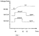
- FIG. 7 depicts an illustrative sequence of actuator state change for the fluidic actuator of FIG. 5 , according to some aspects.
- the switches 519 and 523 Prior to time t0, the switches 519 and 523 are open and the actuator 500 is in a state C1, representing a first level of pressure at membrane 501.
- aperture 502 is opened by closing switch 523.
- switch 519 At the same time, or at approximately the same time, switch 519 is closed, causing the stiffness of membrane 501 to decrease, reducing the pressure in cavity 517, and driving fluid 509 to flow from cavity 518 to cavity 517.
- the actuator state which is dictated by the relative volumes of fluid in cavity 517 and cavity 518, can be adjusted by controlling the magnitude of electrical charge delivered to membrane 501 (e.g., via electrodes 514A and 514B ).
- the charge magnitude can be adjusted by varying voltage source 520 or by varying the duty cycle of electrical pulses using switch 519.
- the actuator reaches a desired state at time t1, the power to active valve membrane 516 is removed by opening switch 523, causing aperture 502 to close.
- the power to membrane 501 is turned off by opening switch 519.
- the actuator state can be maintained while all switches are turn off. This state is illustrated in FIG. 6B .
- a display device can contain multiple such actuators and display units so that an image or other combination of optical elements can be produced. For instance, many instances of the elements shown in FIG. 1 can be arranged in an array and addressed individually so that an image can be produced.
- fluidic display units can each represent a sub-pixel of a display and contain one of a number of primary subtractive colors (e.g., one of red, green, or blue; or one of cyan, magenta or yellow). By displaying a suitable amount of these colors at each sub-pixel, an image that appears to be comprised of many colors can be produced from a display.
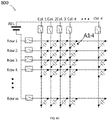
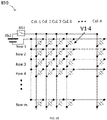
- FIGS. 8A-8B depict an illustrative configuration for providing electrical actuation of an array of fluidic actuators, according to some aspects.
- a connected array of fluidic actuators is depicted, with each active element being represented by a capacitor symbol.
- the depicted array can correspond to, for example, the illustrative fluidic actuator 500 shown in FIG. 5 , wherein the arrangement 800 of FIG. 8A provides for actuation of active membrane 501 and the arrangement 850 of FIG. 8B provides for actuation of active membrane 516.
- illustrative active element A1-4 in FIG. 8A can correspond to the active membrane 501 and allow for actuation of said membrane
- illustrative active element V1-4 in FIG. 8B can correspond to the active membrane 516 and allow for opening and closing of the valve 503.
- each instance of the active membrane 501 in the array 800 can be individually addressed by closing suitable combinations of the row and column switches.
- the row switches can be scanned in a cyclic manner whilst selected column switches are closed in synchronization.
- the valves of each actuator in the array can be collectively opened and closed by opening and closing switch 851 in FIG. 8B .
- switch 851 can be closed to open the valve in each actuator, allowing the fluid to flow in that actuator (as dictated by the state of the corresponding active membrane in the array 800 ).
- switch 851 can be opened.
- a single fluidic actuator 500 can include active membrane A1-4 and active membrane V1-4 and be controlled in the manner described above in relation to FIG. 5 by opening and closing the row 1 and column 4 switches in FIG. 8A (in which case the combination of these switches corresponds to switch 519 in FIG. 5 ) and by opening and closing switch 851 (in which case the combination of these switches corresponds to switch 523 in FIG. 5 ).
- FIG. 9 depicts an illustrative configuration for providing electrical actuation of an array of valves of fluidic actuators, according to some aspects.
- the depicted array 900 can correspond to, for example, the illustrative fluidic actuator 200 shown in FIG. 2 , wherein the array provides for actuation of valves 203 by controlling corresponding switches.
- switch 901 can represent a switch 216 for each of the valves and switch 902 can represent switch 213 for each of the valves.
- This approach can therefore allow opening and closing of all of the valves in the array in concert by opening and closing switches 901 and 902 in an appropriate sequence.
- a single valve control arrangement such as shown in FIG. 9 can enable for comparatively simple wiring relative to actively addressed alternative configurations, and can eliminate the need of multiple control electronics to control the valve.
- a corresponding control diagram for the combined switch valve array of FIG. 9 is shown in FIG. 10 .
- a user can employ user interface 1002, which can be a computer workstation, to provide a vector image or a bitmap image, and make adjustments regarding the image appearance and the timing of display.
- the computing device 1004 can process the image into a suitable format for the display hardware containing desired color state information. This information can be sent to the microcontroller 1006 at a scheduled time.
- Microcontroller 1006 can update the display hardware state by turning on power supply 1010 and timely activating switches 1008, which can correspond to, for example, the illustrative array of switches 800 and switch 850 shown in FIGS. 8A and 8B , respectively.
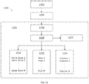
- each row zone can control a group of actuators that correspond to subpixels containing one kind of primary color.
- row zone A, row zone B, and row zone C can respectively control cyan, magenta, and yellow subpixels throughout the display, or throughout a portion of the display.
- FIG. 12 A corresponding control diagram for the combined switch valve array of FIG. 11 is shown in FIG. 12 .
- a user can employ user interface 1202, which can be a computer workstation, to provide a vector image or a bitmap image, and make adjustments regarding the image appearance and the timing of display.
- the computing device 1204 can process the image into a suitable format for the display hardware containing desired color state information. This information can be sent to the microcontroller 1206 at a scheduled time.
- Microcontroller 1206 can update the display hardware state by turning on power supply 1210 and timely activating switches 1208, which can correspond to, for example, the illustrative array of switches 800 and switch 850 shown in FIGS. 8A and 8B , respectively.
- Improvements in display device lifetime are expected to be meaningful employing this multistability mechanism, as the integrated electrical stress experienced by the dielectric elastomer actuator is reduced greatly. For example, if the display device is energized for 1s in the course of displaying an image, and the multistability mechanism is engaged to fix the image in place for the next 7s, electrical stress is removed from the dielectric elastomer element responsible for controlling the ink levels in the display for 7/8ths of the time of operation. Investigations into dielectric elastomer reliability [Zhang, 2017] suggest that dielectric elastomer actuator lifetime can be related to duration of time under electrical stress because of aging processes that degrade the dielectric.
- the present disclosure provides a mechanism to enable 'change and hold' display device functionality in a manner that significantly reduces electrical stress on the active membranes 201 or 501, therefore extending total device lifetime considerably.
- Other combinations of actuator-on/multistability mechanism-off actuator-off/multistability mechanism-on driving schemes can be employed to similar effect, depending on the desired duration of image hold versus image refresh.
- Reductions in power consumption from employing this multistability mechanism are significant, which are dependent on the image refresh rate, duty cycle applied to the dielectric elastomer actuator, and duration of image hold.
- a densely-packed dielectric elastomer actuator array of 972 individual 8.3mm diameter actuators arranged in an 18x18 pixel array, over an area of 1ft2, each operating at 1kV, drawing 0.35uA/actuator would consume 0.34W/ft2 at steady-state when driven at a 100% duty cycle, having an 6s image hold, and a 1s image switching time.
- the system would draw 27mW to display the image without the multistability mechanism.
- the imperfection of fluid sealing in any aperture 210, 416, or 502 within the present system dictates refreshing the multistability mechanism due to fluid leakage through apertures 210, 416, or 502, yielding a power draw of approximately 4mW to maintain the displayed image after power is withdrawn from the active membranes 201, 501, or 516.
- lower amounts of unintended liquid leakage through apertures 210, 416, or 502 via more effective sealing lower power is required to maintain the displayed image, such as 0.4mW for the 27 element array.
Landscapes
- Physics & Mathematics (AREA)
- General Physics & Mathematics (AREA)
- Engineering & Computer Science (AREA)
- Optics & Photonics (AREA)
- Computer Hardware Design (AREA)
- Theoretical Computer Science (AREA)
- Electrochromic Elements, Electrophoresis, Or Variable Reflection Or Absorption Elements (AREA)
- Mechanical Light Control Or Optical Switches (AREA)
- Devices For Indicating Variable Information By Combining Individual Elements (AREA)
Claims (25)
- Dispositif d'affichage (100) configuré pour modifier une propriété optique en déplaçant une quantité d'un premier fluide à travers lequel de la lumière externe peut passer, le dispositif d'affichage comprenant :une unité d'affichage fluidique (110) comprenant au moins une première cavité d'affichage comprenant un premier fluide (411), le premier fluide étant mobile à l'intérieur de la première cavité d'affichage (403, 415) par variation d'une quantité de pression sur la première cavité d'affichage ; etun actionneur fluidique (120) couplé mécaniquement à la première cavité d'affichage de l'unité d'affichage fluidique, l'actionneur fluidique comprenant un deuxième fluide, une première cavité (217, 517) comprenant le deuxième fluide et délimitée au moins en partie par un premier élastomère, une deuxième cavité (218, 518) comprenant le deuxième fluide (209, 509) et délimitée au moins en partie par un deuxième élastomère, un canal reliant la première cavité à la deuxième cavité et à travers lequel le deuxième fluide peut s'écouler, et une vanne (203, 503) configurée pour être manœuvrée électriquement dans un état ouvert ou un état fermé et permettre ou bloquer ainsi un écoulement du deuxième fluide à travers le canal, l'actionneur fluidique étant configuré pour être actionné électriquement pour faire varier la quantité de pression sur la première cavité de l'unité d'affichage fluidique,dans lequel une variation de la pression provoque un déplacement du premier fluide à l'intérieur de l'unité d'affichage fluidique, modifiant ainsi la propriété optique du dispositif d'affichage,dans lequel le deuxième fluide est à une pression à l'intérieur de l'actionneur fluidique supérieure à une pression du premier fluide à l'intérieur de l'unité d'affichage fluidique, etdans lequel le maintien de la vanne dans l'état fermé nécessite moins d'énergie électrique que le maintien de la vanne dans l'état ouvert.
- Dispositif d'affichage de la revendication 1, dans lequel le premier fluide est choisi parmi une encre, un colorant, un pigment, une solution de n'importe lequel des éléments précédents, et une combinaison de ceux-ci.
- Dispositif d'affichage de la revendication 1, dans lequel l'actionneur fluidique comprend au moins un élastomère diélectrique.
- Dispositif d'affichage de la revendication 3, dans lequel l'élastomère diélectrique comprend un film élastomère passif intercalé entre des électrodes (214A, 214B) .
- Dispositif d'affichage de la revendication 3, dans lequel l'élastomère est choisi parmi un élastomère de polyacrylate, le caoutchouc naturel, le caoutchouc de silicone, le caoutchouc chloroprène, le caoutchouc butyle, le caoutchouc isoprène, le caoutchouc nitrile, l'éthylènepropylène-diène monomère (EPDM), 1'acrylonitrilebutadiène-styrène (ABS), le fluorosilicone, un élastomère thermoplastique, le caoutchouc de poly(uréthane), les copolymères de n'importe lesquels des élastomères susmentionnés, les composites des élastomères susmentionnés avec au moins une charge inorganique, et les combinaisons de ceux-ci.
- Dispositif d'affichage de la revendication 3, dans lequel l'actionneur fluidique comprend en outre des électrodes (214A, 214B) fixées à des côtés opposés de l'élastomère diélectrique, et dans lequel la variation d'un potentiel électrique appliqué aux bornes des électrodes fait varier la quantité de pression appliquée à la cavité remplie de fluide de l'unité d'affichage fluidique.
- Dispositif d'affichage de la revendication 1, dans lequel l'actionneur fluidique est configuré pour appliquer une pluralité de pressions différentes à la première cavité d'affichage remplie de fluide de l'unité d'affichage fluidique, et dans lequel le fonctionnement de l'actionneur pour basculer de la production d'une première pression de la pluralité de pressions différentes à une deuxième pression de la pluralité de pressions différentes provoque le déplacement du premier fluide à l'intérieur de l'unité d'affichage fluidique.
- Dispositif d'affichage de la revendication 1, dans lequel le deuxième fluide est choisi parmi la glycérine, les glycols, les polyols, les huiles de silicone, les huiles végétales, les huiles minérales, les huiles pour moteurs, les huiles lubrifiantes, les polyalphaoléfines, les hydrofluoroéthers, les fluorocétones, les esters de silicate, les huiles de synthèse, les hydrocarbures fluorés, et les combinaisons de ceux-ci.
- Dispositif d'affichage de la revendication 1, dans lequel une modification de la propriété optique comporte des changements dans la couleur produite quand de la lumière blanche est réfléchie depuis l'unité d'affichage.
- Dispositif d'affichage de la revendication 1, comprenant en outre une pluralité d'unités d'affichage fluidiques correspondant chacune à un pixel ou un souspixel du dispositif d'affichage et couplées chacune mécaniquement à des actionneurs fluidiques respectifs.
- Dispositif d'affichage de la revendication 1, dans lequel l'unité d'affichage fluidique comprend une deuxième cavité d'affichage et une couche réfléchissante disposée entre la première cavité et la deuxième cavité.
- Dispositif d'affichage de la revendication 1, dans lequel l'actionneur fluidique comprend en outre un ou plusieurs réflecteurs de telle sorte que de la lumière visible peut passer à travers au moins une partie de l'unité d'affichage fluidique, être réfléchie par le réflecteur, et être émise hors de l'unité d'affichage dans une direction de visualisation.
- Dispositif d'affichage de la revendication 12, dans lequel la propriété optique est une couleur de la lumière visible émise hors de l'unité d'affichage ; et
dans lequel le premier fluide est choisi parmi une encre, un colorant, un pigment, une solution de n'importe lequel des éléments précédents, et une combinaison de ceux-ci. - Dispositif d'affichage de la revendication 12, dans lequel le ou les réflecteurs comprennent un ou plusieurs éléments parmi du papier, du Téflon, des surfaces peintes en blanc, des particules d'oxyde de titane, des revêtements de sulfate de baryum, des miroirs en argent, des revêtements d'oxyde d'indium et d'étain, ou des combinaisons de ceux-ci.
- Dispositif d'affichage de la revendication 1, dans lequel l'unité d'affichage comprend en outre une ou plusieurs sources de lumière visible configurées de telle sorte qu'une lumière visible peut passer à travers au moins une partie de l'unité d'affichage fluidique et être émise hors de l'unité d'affichage dans une direction de visualisation ;dans lequel la propriété optique est une couleur de la lumière visible émise hors de l'unité d'affichage ; etdans lequel le premier fluide est choisi parmi une encre, un colorant, un pigment, une solution de n'importe lequel des éléments précédents, et une combinaison de ceux-ci.
- Dispositif d'affichage de la revendication 1, dans lequel le maintien de la vanne dans l'état fermé ne nécessite aucune énergie électrique.
- Dispositif d'affichage de la revendication 1, comprenant en outre des électrodes fixées à des côtés opposés du premier élastomère, et dans lequel l'application d'un potentiel électrique aux bornes des électrodes modifie la forme du premier élastomère et provoque l'écoulement d'un fluide depuis la deuxième cavité jusqu'à l'intérieur de la première cavité par le biais du canal.
- Dispositif d'affichage de la revendication 1, dans lequel la vanne est configurée pour être manœuvrée électriquement dans au moins trois états qui incluent l'état ouvert et l'état fermé.
- Dispositif d'affichage de la revendication 1, dans lequel le deuxième fluide de la première cavité et la deuxième cavité comprend une huile diélectrique.
- Dispositif d'affichage de la revendication 1, dans lequel :la vanne comprend un clapet (204) agencé pour se déplacer autour d'au moins un axe ;l'actionneur comprend au moins une première électrode (211) à proximité du clapet ; etl'actionneur est configuré pour charger électriquement la première électrode, attirant ainsi le clapet vers la première électrode et manœuvrant la vanne dans l'état ouvert.
- Dispositif d'affichage de la revendication 20, dans lequel l'actionneur comprend une deuxième électrode (221) et l'actionneur est configuré pour charger électriquement la deuxième électrode, attirant ainsi le clapet vers la deuxième électrode et manœuvrant la vanne dans l'état fermé.
- Dispositif d'affichage de la revendication 20, dans lequel le clapet est disposé sur une ouverture du canal et s'étend au-delà d'au moins une dimension de l'ouverture de telle sorte que le clapet ne peut pas passer à travers l'ouverture.
- Dispositif d'affichage de la revendication 20, dans lequel la vanne comprend une troisième cavité (511) comprenant un fluide (529) et délimitée au moins en partie par un élastomère diélectrique, l'élastomère diélectrique comprenant des électrodes (521A, 521B) fixées à des côtés opposés d'un troisième élastomère ;dans lequel la troisième cavité est disposée à proximité d'une ouverture du canal ; etdans lequel l'actionneur est configuré pour appliquer un premier potentiel électrique aux bornes des électrodes fixées au troisième élastomère, modifiant ainsi la forme du troisième élastomère et conduisant la troisième cavité à permettre l'écoulement d'un fluide à travers l'ouverture du canal.
- Dispositif d'affichage de la revendication 23, dans lequel l'actionneur est configuré pour appliquer un deuxième potentiel électrique aux bornes des électrodes fixées au troisième élastomère, le deuxième potentiel électrique étant inférieur au premier potentiel électrique, conduisant ainsi la troisième cavité à bloquer l'écoulement d'un fluide à travers l'ouverture du canal.
- Dispositif d'affichage de la revendication 24, dans lequel le maintien du deuxième potentiel électrique aux bornes des électrodes fixées au troisième élastomère ne nécessite aucune énergie.
Applications Claiming Priority (2)
| Application Number | Priority Date | Filing Date | Title |
|---|---|---|---|
| US201862751412P | 2018-10-26 | 2018-10-26 | |
| PCT/US2019/058196 WO2020087028A1 (fr) | 2018-10-26 | 2019-10-25 | Techniques d'affichage incorporant des actionneurs fluidiques et systèmes et procédés associés |
Publications (2)
| Publication Number | Publication Date |
|---|---|
| EP3857537A1 EP3857537A1 (fr) | 2021-08-04 |
| EP3857537B1 true EP3857537B1 (fr) | 2022-08-31 |
Family
ID=68583524
Family Applications (1)
| Application Number | Title | Priority Date | Filing Date |
|---|---|---|---|
| EP19805462.9A Not-in-force EP3857537B1 (fr) | 2018-10-26 | 2019-10-25 | Techniques d'affichage incorporant actionneurs fluidiques et systèmes et procédés associés |
Country Status (5)
| Country | Link |
|---|---|
| US (2) | US11086121B2 (fr) |
| EP (1) | EP3857537B1 (fr) |
| JP (1) | JP2022509371A (fr) |
| CN (1) | CN113168816B (fr) |
| WO (1) | WO2020087028A1 (fr) |
Families Citing this family (4)
| Publication number | Priority date | Publication date | Assignee | Title |
|---|---|---|---|---|
| EP3857537B1 (fr) * | 2018-10-26 | 2022-08-31 | Solchroma Technologies, Inc. | Techniques d'affichage incorporant actionneurs fluidiques et systèmes et procédés associés |
| US11796789B2 (en) * | 2020-09-01 | 2023-10-24 | Wisconsin Alumni Research Foundation | Pinned aperture light modulator and method |
| WO2022245713A1 (fr) * | 2021-05-17 | 2022-11-24 | Solchroma Technologies, Inc. | Dispositif d'affichage réfléchissant avec éléments optiques de réduction d'espace mort |
| WO2023056074A1 (fr) | 2021-10-01 | 2023-04-06 | Solchroma Technologies, Inc. | Appareil d'affichage réfléchissant avec fluide à absorption optique |
Family Cites Families (20)
| Publication number | Priority date | Publication date | Assignee | Title |
|---|---|---|---|---|
| US6073479A (en) * | 1998-11-13 | 2000-06-13 | General Electric Company | Dewpoint sensor |
| AUPQ669000A0 (en) * | 2000-04-04 | 2000-05-04 | Cooke, Richard | Screen display device |
| US6490960B1 (en) * | 2001-07-11 | 2002-12-10 | Xerox Corporation | Muscle-emulating PC board actuator |
| US6807892B2 (en) * | 2002-12-30 | 2004-10-26 | Xerox Corporation | Pneumatic actuator with elastomeric membrane and low-power electrostatic flap valve arrangement |
| JP2007512567A (ja) * | 2003-11-21 | 2007-05-17 | コーニンクレッカ フィリップス エレクトロニクス エヌ ヴィ | 電気泳動表示装置のクロストーク補償 |
| US8928562B2 (en) * | 2003-11-25 | 2015-01-06 | E Ink Corporation | Electro-optic displays, and methods for driving same |
| WO2006015044A1 (fr) * | 2004-07-27 | 2006-02-09 | E Ink Corporation | Affichages electro-optiques |
| JP4690079B2 (ja) * | 2005-03-04 | 2011-06-01 | セイコーエプソン株式会社 | 電気泳動装置とその駆動方法、及び電子機器 |
| CN100510834C (zh) * | 2007-11-20 | 2009-07-08 | 北京派瑞根科技开发有限公司 | 基于电润湿技术的显示单元和显示装置 |
| US8561963B2 (en) * | 2007-12-19 | 2013-10-22 | Palo Alto Research Center Incorporated | Electrostatically addressable microvalves |
| US20090279158A1 (en) * | 2008-05-08 | 2009-11-12 | Palo Alto Research Center Incorporated | Fluid Actuator For Digitally Controllable Microfluidic Display |
| JP5159597B2 (ja) * | 2008-12-25 | 2013-03-06 | 株式会社サムスン横浜研究所 | 反射型表示装置 |
| WO2010126512A1 (fr) * | 2009-04-30 | 2010-11-04 | Hewlett-Packard Development Company, L.P. | Dispositif d'affichage couleur réfléchissant |
| FR2955404B1 (fr) * | 2010-01-18 | 2012-01-27 | Commissariat Energie Atomique | Actionneur fluidique et dispositif d'affichage a actionneurs fluidiques |
| EP2603832A4 (fr) * | 2010-08-09 | 2014-07-30 | Hewlett Packard Development Co | Système et procédé destinés à des affichages électro-optiques à trois états |
| US20120086691A1 (en) * | 2010-10-06 | 2012-04-12 | Polymer Vision B.V. | Electrofluidic chromatophore (efc) display apparatus |
| WO2013112498A1 (fr) | 2012-01-23 | 2013-08-01 | President And Fellows Of Harvard College | Dispositif et affichage de pixels utilisant de l'encre liquide et des élastomères |
| WO2014077931A2 (fr) * | 2012-08-28 | 2014-05-22 | President And Fellows Of Harvard College | Dispositifs optiques et acoustiques adaptatifs |
| FR3037152B1 (fr) * | 2015-06-03 | 2017-07-14 | Wavelens | Dispositif optique a ouverture variable |
| EP3857537B1 (fr) * | 2018-10-26 | 2022-08-31 | Solchroma Technologies, Inc. | Techniques d'affichage incorporant actionneurs fluidiques et systèmes et procédés associés |
-
2019
- 2019-10-25 EP EP19805462.9A patent/EP3857537B1/fr not_active Not-in-force
- 2019-10-25 CN CN201980079867.1A patent/CN113168816B/zh not_active Expired - Fee Related
- 2019-10-25 WO PCT/US2019/058196 patent/WO2020087028A1/fr not_active Ceased
- 2019-10-25 US US17/046,904 patent/US11086121B2/en not_active Expired - Fee Related
- 2019-10-25 JP JP2021547669A patent/JP2022509371A/ja active Pending
-
2021
- 2021-08-06 US US17/396,479 patent/US20220026704A1/en not_active Abandoned
Also Published As
| Publication number | Publication date |
|---|---|
| US20220026704A1 (en) | 2022-01-27 |
| US20210157123A1 (en) | 2021-05-27 |
| JP2022509371A (ja) | 2022-01-20 |
| US11086121B2 (en) | 2021-08-10 |
| EP3857537A1 (fr) | 2021-08-04 |
| CN113168816B (zh) | 2023-09-12 |
| WO2020087028A1 (fr) | 2020-04-30 |
| CN113168816A (zh) | 2021-07-23 |
Similar Documents
| Publication | Publication Date | Title |
|---|---|---|
| US20220026704A1 (en) | Display techniques incorporating fluidic actuators and related systems and methods | |
| US9335539B2 (en) | Pixel device and display using liquid ink and elastomers | |
| US9323041B2 (en) | Electromechanical systems display apparatus incorporating charge dissipation surfaces | |
| CN113359366B (zh) | 可变颜色和透射覆盖物 | |
| CN102834859B (zh) | 用于控制显示装置的电路 | |
| CN104662899B (zh) | 使用机电显示元件的三维(3d)图像生成 | |
| WO2011036994A1 (fr) | Dispositif d'affichage à gamme complète de couleurs utilisant des éléments de pixels multicolores et procédé correspondant | |
| EP3256903B1 (fr) | Laminate electrophoretique comportant des particules de deux sortes et utilisable dans des vitrages intelligents | |
| CN103988249B (zh) | 用于控制显示设备的电路 | |
| TWI775662B (zh) | 電光顯示器 | |
| TWI519813B (zh) | 具有交錯之顯示元件排列之顯示器 | |
| US20230135357A1 (en) | Driving waveforms for reflective displays and reflective displays using the same | |
| US20250087175A1 (en) | Microfluid Display Devices and Methods of Use | |
| CN121763557A (zh) | 自供能变色组件、彩色智能窗系统及其控制方法和介质 | |
| WO2023056074A1 (fr) | Appareil d'affichage réfléchissant avec fluide à absorption optique | |
| HK40049276A (en) | Variable color and transmission coverings | |
| HK1245488B (zh) | 可变颜色和透射覆盖物 | |
| HK1136901A1 (en) | Methods for driving electrophoretic displays using dielectrophoretic forces |
Legal Events
| Date | Code | Title | Description |
|---|---|---|---|
| STAA | Information on the status of an ep patent application or granted ep patent |
Free format text: STATUS: UNKNOWN |
|
| STAA | Information on the status of an ep patent application or granted ep patent |
Free format text: STATUS: THE INTERNATIONAL PUBLICATION HAS BEEN MADE |
|
| PUAI | Public reference made under article 153(3) epc to a published international application that has entered the european phase |
Free format text: ORIGINAL CODE: 0009012 |
|
| STAA | Information on the status of an ep patent application or granted ep patent |
Free format text: STATUS: REQUEST FOR EXAMINATION WAS MADE |
|
| 17P | Request for examination filed |
Effective date: 20210426 |
|
| AK | Designated contracting states |
Kind code of ref document: A1 Designated state(s): AL AT BE BG CH CY CZ DE DK EE ES FI FR GB GR HR HU IE IS IT LI LT LU LV MC MK MT NL NO PL PT RO RS SE SI SK SM TR |
|
| STAA | Information on the status of an ep patent application or granted ep patent |
Free format text: STATUS: EXAMINATION IS IN PROGRESS |
|
| 17Q | First examination report despatched |
Effective date: 20210920 |
|
| DAV | Request for validation of the european patent (deleted) | ||
| DAX | Request for extension of the european patent (deleted) | ||
| GRAP | Despatch of communication of intention to grant a patent |
Free format text: ORIGINAL CODE: EPIDOSNIGR1 |
|
| STAA | Information on the status of an ep patent application or granted ep patent |
Free format text: STATUS: GRANT OF PATENT IS INTENDED |
|
| INTG | Intention to grant announced |
Effective date: 20220317 |
|
| GRAS | Grant fee paid |
Free format text: ORIGINAL CODE: EPIDOSNIGR3 |
|
| GRAA | (expected) grant |
Free format text: ORIGINAL CODE: 0009210 |
|
| STAA | Information on the status of an ep patent application or granted ep patent |
Free format text: STATUS: THE PATENT HAS BEEN GRANTED |
|
| AK | Designated contracting states |
Kind code of ref document: B1 Designated state(s): AL AT BE BG CH CY CZ DE DK EE ES FI FR GB GR HR HU IE IS IT LI LT LU LV MC MK MT NL NO PL PT RO RS SE SI SK SM TR |
|
| REG | Reference to a national code |
Ref country code: CH Ref legal event code: EP Ref country code: GB Ref legal event code: FG4D |
|
| REG | Reference to a national code |
Ref country code: AT Ref legal event code: REF Ref document number: 1515878 Country of ref document: AT Kind code of ref document: T Effective date: 20220915 |
|
| REG | Reference to a national code |
Ref country code: DE Ref legal event code: R096 Ref document number: 602019019072 Country of ref document: DE |
|
| REG | Reference to a national code |
Ref country code: IE Ref legal event code: FG4D |
|
| REG | Reference to a national code |
Ref country code: LT Ref legal event code: MG9D |
|
| REG | Reference to a national code |
Ref country code: NL Ref legal event code: MP Effective date: 20220831 |
|
| PG25 | Lapsed in a contracting state [announced via postgrant information from national office to epo] |
Ref country code: SE Free format text: LAPSE BECAUSE OF FAILURE TO SUBMIT A TRANSLATION OF THE DESCRIPTION OR TO PAY THE FEE WITHIN THE PRESCRIBED TIME-LIMIT Effective date: 20220831 Ref country code: RS Free format text: LAPSE BECAUSE OF FAILURE TO SUBMIT A TRANSLATION OF THE DESCRIPTION OR TO PAY THE FEE WITHIN THE PRESCRIBED TIME-LIMIT Effective date: 20220831 Ref country code: NO Free format text: LAPSE BECAUSE OF FAILURE TO SUBMIT A TRANSLATION OF THE DESCRIPTION OR TO PAY THE FEE WITHIN THE PRESCRIBED TIME-LIMIT Effective date: 20221130 Ref country code: LV Free format text: LAPSE BECAUSE OF FAILURE TO SUBMIT A TRANSLATION OF THE DESCRIPTION OR TO PAY THE FEE WITHIN THE PRESCRIBED TIME-LIMIT Effective date: 20220831 Ref country code: LT Free format text: LAPSE BECAUSE OF FAILURE TO SUBMIT A TRANSLATION OF THE DESCRIPTION OR TO PAY THE FEE WITHIN THE PRESCRIBED TIME-LIMIT Effective date: 20220831 Ref country code: FI Free format text: LAPSE BECAUSE OF FAILURE TO SUBMIT A TRANSLATION OF THE DESCRIPTION OR TO PAY THE FEE WITHIN THE PRESCRIBED TIME-LIMIT Effective date: 20220831 |
|
| REG | Reference to a national code |
Ref country code: AT Ref legal event code: MK05 Ref document number: 1515878 Country of ref document: AT Kind code of ref document: T Effective date: 20220831 |
|
| PG25 | Lapsed in a contracting state [announced via postgrant information from national office to epo] |
Ref country code: PL Free format text: LAPSE BECAUSE OF FAILURE TO SUBMIT A TRANSLATION OF THE DESCRIPTION OR TO PAY THE FEE WITHIN THE PRESCRIBED TIME-LIMIT Effective date: 20220831 Ref country code: IS Free format text: LAPSE BECAUSE OF FAILURE TO SUBMIT A TRANSLATION OF THE DESCRIPTION OR TO PAY THE FEE WITHIN THE PRESCRIBED TIME-LIMIT Effective date: 20221231 Ref country code: HR Free format text: LAPSE BECAUSE OF FAILURE TO SUBMIT A TRANSLATION OF THE DESCRIPTION OR TO PAY THE FEE WITHIN THE PRESCRIBED TIME-LIMIT Effective date: 20220831 Ref country code: GR Free format text: LAPSE BECAUSE OF FAILURE TO SUBMIT A TRANSLATION OF THE DESCRIPTION OR TO PAY THE FEE WITHIN THE PRESCRIBED TIME-LIMIT Effective date: 20221201 |
|
| PG25 | Lapsed in a contracting state [announced via postgrant information from national office to epo] |
Ref country code: SM Free format text: LAPSE BECAUSE OF FAILURE TO SUBMIT A TRANSLATION OF THE DESCRIPTION OR TO PAY THE FEE WITHIN THE PRESCRIBED TIME-LIMIT Effective date: 20220831 Ref country code: RO Free format text: LAPSE BECAUSE OF FAILURE TO SUBMIT A TRANSLATION OF THE DESCRIPTION OR TO PAY THE FEE WITHIN THE PRESCRIBED TIME-LIMIT Effective date: 20220831 Ref country code: PT Free format text: LAPSE BECAUSE OF FAILURE TO SUBMIT A TRANSLATION OF THE DESCRIPTION OR TO PAY THE FEE WITHIN THE PRESCRIBED TIME-LIMIT Effective date: 20230102 Ref country code: ES Free format text: LAPSE BECAUSE OF FAILURE TO SUBMIT A TRANSLATION OF THE DESCRIPTION OR TO PAY THE FEE WITHIN THE PRESCRIBED TIME-LIMIT Effective date: 20220831 Ref country code: DK Free format text: LAPSE BECAUSE OF FAILURE TO SUBMIT A TRANSLATION OF THE DESCRIPTION OR TO PAY THE FEE WITHIN THE PRESCRIBED TIME-LIMIT Effective date: 20220831 Ref country code: CZ Free format text: LAPSE BECAUSE OF FAILURE TO SUBMIT A TRANSLATION OF THE DESCRIPTION OR TO PAY THE FEE WITHIN THE PRESCRIBED TIME-LIMIT Effective date: 20220831 Ref country code: AT Free format text: LAPSE BECAUSE OF FAILURE TO SUBMIT A TRANSLATION OF THE DESCRIPTION OR TO PAY THE FEE WITHIN THE PRESCRIBED TIME-LIMIT Effective date: 20220831 |
|
| PG25 | Lapsed in a contracting state [announced via postgrant information from national office to epo] |
Ref country code: SK Free format text: LAPSE BECAUSE OF FAILURE TO SUBMIT A TRANSLATION OF THE DESCRIPTION OR TO PAY THE FEE WITHIN THE PRESCRIBED TIME-LIMIT Effective date: 20220831 Ref country code: MC Free format text: LAPSE BECAUSE OF FAILURE TO SUBMIT A TRANSLATION OF THE DESCRIPTION OR TO PAY THE FEE WITHIN THE PRESCRIBED TIME-LIMIT Effective date: 20220831 Ref country code: EE Free format text: LAPSE BECAUSE OF FAILURE TO SUBMIT A TRANSLATION OF THE DESCRIPTION OR TO PAY THE FEE WITHIN THE PRESCRIBED TIME-LIMIT Effective date: 20220831 |
|
| REG | Reference to a national code |
Ref country code: CH Ref legal event code: PL |
|
| REG | Reference to a national code |
Ref country code: DE Ref legal event code: R097 Ref document number: 602019019072 Country of ref document: DE |
|
| REG | Reference to a national code |
Ref country code: BE Ref legal event code: MM Effective date: 20221031 |
|
| PG25 | Lapsed in a contracting state [announced via postgrant information from national office to epo] |
Ref country code: NL Free format text: LAPSE BECAUSE OF FAILURE TO SUBMIT A TRANSLATION OF THE DESCRIPTION OR TO PAY THE FEE WITHIN THE PRESCRIBED TIME-LIMIT Effective date: 20220831 Ref country code: LU Free format text: LAPSE BECAUSE OF NON-PAYMENT OF DUE FEES Effective date: 20221025 Ref country code: AL Free format text: LAPSE BECAUSE OF FAILURE TO SUBMIT A TRANSLATION OF THE DESCRIPTION OR TO PAY THE FEE WITHIN THE PRESCRIBED TIME-LIMIT Effective date: 20220831 |
|
| P01 | Opt-out of the competence of the unified patent court (upc) registered |
Effective date: 20230526 |
|
| PLBE | No opposition filed within time limit |
Free format text: ORIGINAL CODE: 0009261 |
|
| STAA | Information on the status of an ep patent application or granted ep patent |
Free format text: STATUS: NO OPPOSITION FILED WITHIN TIME LIMIT |
|
| PG25 | Lapsed in a contracting state [announced via postgrant information from national office to epo] |
Ref country code: LI Free format text: LAPSE BECAUSE OF NON-PAYMENT OF DUE FEES Effective date: 20221031 Ref country code: CH Free format text: LAPSE BECAUSE OF NON-PAYMENT OF DUE FEES Effective date: 20221031 |
|
| 26N | No opposition filed |
Effective date: 20230601 |
|
| PG25 | Lapsed in a contracting state [announced via postgrant information from national office to epo] |
Ref country code: SI Free format text: LAPSE BECAUSE OF FAILURE TO SUBMIT A TRANSLATION OF THE DESCRIPTION OR TO PAY THE FEE WITHIN THE PRESCRIBED TIME-LIMIT Effective date: 20220831 |
|
| PG25 | Lapsed in a contracting state [announced via postgrant information from national office to epo] |
Ref country code: BE Free format text: LAPSE BECAUSE OF NON-PAYMENT OF DUE FEES Effective date: 20221031 |
|
| PG25 | Lapsed in a contracting state [announced via postgrant information from national office to epo] |
Ref country code: IE Free format text: LAPSE BECAUSE OF NON-PAYMENT OF DUE FEES Effective date: 20221025 |
|
| PGFP | Annual fee paid to national office [announced via postgrant information from national office to epo] |
Ref country code: GB Payment date: 20231030 Year of fee payment: 5 |
|
| PGFP | Annual fee paid to national office [announced via postgrant information from national office to epo] |
Ref country code: FR Payment date: 20231031 Year of fee payment: 5 Ref country code: DE Payment date: 20231121 Year of fee payment: 5 |
|
| PG25 | Lapsed in a contracting state [announced via postgrant information from national office to epo] |
Ref country code: CY Free format text: LAPSE BECAUSE OF FAILURE TO SUBMIT A TRANSLATION OF THE DESCRIPTION OR TO PAY THE FEE WITHIN THE PRESCRIBED TIME-LIMIT Effective date: 20220831 |
|
| PG25 | Lapsed in a contracting state [announced via postgrant information from national office to epo] |
Ref country code: MK Free format text: LAPSE BECAUSE OF FAILURE TO SUBMIT A TRANSLATION OF THE DESCRIPTION OR TO PAY THE FEE WITHIN THE PRESCRIBED TIME-LIMIT Effective date: 20220831 Ref country code: IT Free format text: LAPSE BECAUSE OF FAILURE TO SUBMIT A TRANSLATION OF THE DESCRIPTION OR TO PAY THE FEE WITHIN THE PRESCRIBED TIME-LIMIT Effective date: 20220831 Ref country code: HU Free format text: LAPSE BECAUSE OF FAILURE TO SUBMIT A TRANSLATION OF THE DESCRIPTION OR TO PAY THE FEE WITHIN THE PRESCRIBED TIME-LIMIT; INVALID AB INITIO Effective date: 20191025 |
|
| PG25 | Lapsed in a contracting state [announced via postgrant information from national office to epo] |
Ref country code: BG Free format text: LAPSE BECAUSE OF FAILURE TO SUBMIT A TRANSLATION OF THE DESCRIPTION OR TO PAY THE FEE WITHIN THE PRESCRIBED TIME-LIMIT Effective date: 20220831 |
|
| PG25 | Lapsed in a contracting state [announced via postgrant information from national office to epo] |
Ref country code: MT Free format text: LAPSE BECAUSE OF FAILURE TO SUBMIT A TRANSLATION OF THE DESCRIPTION OR TO PAY THE FEE WITHIN THE PRESCRIBED TIME-LIMIT Effective date: 20220831 |
|
| REG | Reference to a national code |
Ref country code: DE Ref legal event code: R119 Ref document number: 602019019072 Country of ref document: DE |
|
| GBPC | Gb: european patent ceased through non-payment of renewal fee |
Effective date: 20241025 |
|
| PG25 | Lapsed in a contracting state [announced via postgrant information from national office to epo] |
Ref country code: DE Free format text: LAPSE BECAUSE OF NON-PAYMENT OF DUE FEES Effective date: 20250501 |
|
| PG25 | Lapsed in a contracting state [announced via postgrant information from national office to epo] |
Ref country code: GB Free format text: LAPSE BECAUSE OF NON-PAYMENT OF DUE FEES Effective date: 20241025 |
|
| PG25 | Lapsed in a contracting state [announced via postgrant information from national office to epo] |
Ref country code: FR Free format text: LAPSE BECAUSE OF NON-PAYMENT OF DUE FEES Effective date: 20241031 |
|
| PG25 | Lapsed in a contracting state [announced via postgrant information from national office to epo] |
Ref country code: TR Free format text: LAPSE BECAUSE OF FAILURE TO SUBMIT A TRANSLATION OF THE DESCRIPTION OR TO PAY THE FEE WITHIN THE PRESCRIBED TIME-LIMIT Effective date: 20220831 |