EP3857724B1 - Uplink- und downlink-reziprozitätsverwaltung von interferenz - Google Patents
Uplink- und downlink-reziprozitätsverwaltung von interferenz Download PDFInfo
- Publication number
- EP3857724B1 EP3857724B1 EP18789698.0A EP18789698A EP3857724B1 EP 3857724 B1 EP3857724 B1 EP 3857724B1 EP 18789698 A EP18789698 A EP 18789698A EP 3857724 B1 EP3857724 B1 EP 3857724B1
- Authority
- EP
- European Patent Office
- Prior art keywords
- sounding
- wireless devices
- cluster
- interference
- signal
- Prior art date
- Legal status (The legal status is an assumption and is not a legal conclusion. Google has not performed a legal analysis and makes no representation as to the accuracy of the status listed.)
- Active
Links
Images





Classifications
-
- H—ELECTRICITY
- H04—ELECTRIC COMMUNICATION TECHNIQUE
- H04B—TRANSMISSION
- H04B7/00—Radio transmission systems, i.e. using radiation field
- H04B7/02—Diversity systems; Multi-antenna system, i.e. transmission or reception using multiple antennas
- H04B7/04—Diversity systems; Multi-antenna system, i.e. transmission or reception using multiple antennas using two or more spaced independent antennas
- H04B7/0413—MIMO systems
- H04B7/0456—Selection of precoding matrices or codebooks, e.g. using matrices antenna weighting
-
- H—ELECTRICITY
- H04—ELECTRIC COMMUNICATION TECHNIQUE
- H04B—TRANSMISSION
- H04B7/00—Radio transmission systems, i.e. using radiation field
- H04B7/02—Diversity systems; Multi-antenna system, i.e. transmission or reception using multiple antennas
- H04B7/04—Diversity systems; Multi-antenna system, i.e. transmission or reception using multiple antennas using two or more spaced independent antennas
- H04B7/06—Diversity systems; Multi-antenna system, i.e. transmission or reception using multiple antennas using two or more spaced independent antennas at the transmitting station
- H04B7/0613—Diversity systems; Multi-antenna system, i.e. transmission or reception using multiple antennas using two or more spaced independent antennas at the transmitting station using simultaneous transmission
- H04B7/0615—Diversity systems; Multi-antenna system, i.e. transmission or reception using multiple antennas using two or more spaced independent antennas at the transmitting station using simultaneous transmission of weighted versions of same signal
- H04B7/0617—Diversity systems; Multi-antenna system, i.e. transmission or reception using multiple antennas using two or more spaced independent antennas at the transmitting station using simultaneous transmission of weighted versions of same signal for beam forming
-
- H—ELECTRICITY
- H04—ELECTRIC COMMUNICATION TECHNIQUE
- H04J—MULTIPLEX COMMUNICATION
- H04J11/00—Orthogonal multiplex systems, e.g. using WALSH codes
- H04J11/0023—Interference mitigation or co-ordination
- H04J11/0026—Interference mitigation or co-ordination of multi-user interference
- H04J11/003—Interference mitigation or co-ordination of multi-user interference at the transmitter
-
- H—ELECTRICITY
- H04—ELECTRIC COMMUNICATION TECHNIQUE
- H04J—MULTIPLEX COMMUNICATION
- H04J11/00—Orthogonal multiplex systems, e.g. using WALSH codes
- H04J11/0023—Interference mitigation or co-ordination
- H04J11/005—Interference mitigation or co-ordination of intercell interference
- H04J11/0053—Interference mitigation or co-ordination of intercell interference using co-ordinated multipoint transmission/reception
-
- H—ELECTRICITY
- H04—ELECTRIC COMMUNICATION TECHNIQUE
- H04L—TRANSMISSION OF DIGITAL INFORMATION, e.g. TELEGRAPHIC COMMUNICATION
- H04L25/00—Baseband systems
- H04L25/02—Details ; arrangements for supplying electrical power along data transmission lines
- H04L25/0202—Channel estimation
- H04L25/0204—Channel estimation of multiple channels
-
- H—ELECTRICITY
- H04—ELECTRIC COMMUNICATION TECHNIQUE
- H04L—TRANSMISSION OF DIGITAL INFORMATION, e.g. TELEGRAPHIC COMMUNICATION
- H04L25/00—Baseband systems
- H04L25/02—Details ; arrangements for supplying electrical power along data transmission lines
- H04L25/0202—Channel estimation
- H04L25/021—Estimation of channel covariance
-
- H—ELECTRICITY
- H04—ELECTRIC COMMUNICATION TECHNIQUE
- H04L—TRANSMISSION OF DIGITAL INFORMATION, e.g. TELEGRAPHIC COMMUNICATION
- H04L25/00—Baseband systems
- H04L25/02—Details ; arrangements for supplying electrical power along data transmission lines
- H04L25/0202—Channel estimation
- H04L25/0224—Channel estimation using sounding signals
-
- H—ELECTRICITY
- H04—ELECTRIC COMMUNICATION TECHNIQUE
- H04L—TRANSMISSION OF DIGITAL INFORMATION, e.g. TELEGRAPHIC COMMUNICATION
- H04L25/00—Baseband systems
- H04L25/02—Details ; arrangements for supplying electrical power along data transmission lines
- H04L25/03—Shaping networks in transmitter or receiver, e.g. adaptive shaping networks
- H04L25/03006—Arrangements for removing intersymbol interference
- H04L25/03343—Arrangements at the transmitter end
Definitions
- the present disclosure relates to methods and devices for management of interference in wireless communication systems.
- the disclosure relates to methods and devices for uplink and downlink reciprocity-based management of interference.
- the disclosure also relates to corresponding computer programs.
- LTE is also sometimes referred to as Evolved Universal Terrestrial Access Network, E-UTRAN.
- LTE is a technology for realizing high-speed packet-based communication that can reach high data rates both in the downlink and in the uplink, and is a next generation mobile communication system relative to UMTS. LTE brings significant improvements in capacity and performance over previous radio access technologies.
- the Universal Terrestrial Radio Access Network is the radio access network of a UMTS and Evolved UTRAN, E-UTRAN, is the radio access network of an LTE system.
- a User Equipment UE
- a Radio Base Station commonly referred to as a NodeB, NB, in UMTS, and as an evolved NodeB, eNB or eNodeB, in LTE.
- RBS is a general term for a radio network node capable of transmitting radio signals to a UE and receiving signals transmitted by a UE.
- wireless terminal or “wireless device” encompass any device which is able to communicate wirelessly with another device, as well as, optionally, with an access node of a wireless network, by transmitting and/or receiving wireless signals.
- wireless device encompasses, but is not limited to: a user equipment, e.g. an LTE UE, a mobile terminal, a stationary or mobile wireless device for machine-to-machine communication, an integrated or embedded wireless card, an externally plugged in wireless card, a dongle etc.
- user equipment is sometimes used to exemplify various embodiments.
- TX antennas are located in an antenna grid where all antenna elements effectively help to create a narrow beam towards the desired receiver. This is essentially the same as classical beamforming, but typically done considering several users at the same time. Hence, beams are directed to several users.
- the TX antennas are spread out over the physical network, similar to today's cellular network deployments, but with a coherent transmission instead of today's uncoordinated each-cell-for-itself transmission.
- the Coordinated Multipoint in LTE is essentially a range of different techniques that enable the dynamic coordination of transmission and reception over a variety of different base stations.
- the aim is to improve overall quality for the user as well as improving the utilization of the network.
- the eNB s dynamically coordinate their transmissions to provide joint scheduling and transmissions, as well as proving joint processing of the received signals. In this way a UE at the edge of a cell is able to be served by two or more eNBs to improve signals reception/transmission and increase throughput particularly under cell edge conditions.
- a CoMP cluster is a set of transmission antennas which are transmitting in a coherent and coordinated way to a set of wireless devices.
- the size of each cluster will have to be limited in order to create a reasonable load on the network baseband, backhaul communication etc. This will typically lead to incoherent interference between clusters. Though, today's precoder algorithms typically do not take this inter-cluster interference into account.
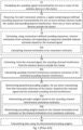
- Figure 1 describes a prior art method proposed to compute downlink precoding weights which mitigate inter-cluster interference disclosed in PCT Application WO 2016/155758 A1, Methods and Arrangements for Mitigating Inter-Cluster Interference, filed October 6, 2016 .
- This method is known in the art as "Reciprocity Assisted Interference-Aware Transmission” or "RAIT”.
- RAIT Reciprocity Assisted Interference-Aware Transmission
- One of the key features of RAIT is inter- and intra-cell interference suppression for automatic interference handling in a network, based only on sounding information (no backhaul between sites required).
- inter-cell interference mitigation is to estimate the inter-cell spatial interference covariance matrix in the uplink, based on sounding information; assume that the spatial distribution of the uplink inter-cell interferers is representative of the UE spatial properties; and that the downlink transmission should be made with the UE spatial awareness to avoid sending interference in their "direction" (nullforming to inter-cell interfered UEs in the downlink).
- uplink inter-cell interference covariance estimates are obtained and used, based on reciprocity, as information about the spatial distribution of inter-cell UEs, which should not be interfered "too much" in the downlink.
- the sounding channel interference covariance estimates of the estimated sounding channel interference are associated with the strength of the uplink inter-cell interferers. Still, a strong uplink interferer should not necessarily be associated with an inter-cell UE in the downlink which should be "protected” from interference in the downlink. There are multiple reasons for this. As an example, the device could be doing only uplink transmissions at the moment of interest, but knowledge of this would require joint inter-cell scheduling.
- a problematic case is one which can be covered without joint inter-cell scheduling, and which relies instead on UE-specific handling.
- UE have different characteristics (e.g. number of RX/TX antennas) and capabilities (e.g. able to do Interference Rejection Combining (IRC), or even Interference Cancelation (IC) at RX).
- IRC Interference Rejection Combining
- IC Interference Cancelation
- US 2015/078186 A1 discloses a method that includes interference control at transmitters and interference mitigation at receivers in a wireless communication system.
- Methods disclosed in the document exploit the interference sensitivity at neighboring terminals by taking into account the reciprocity of propagation radio channels in Time Division Duplexing systems (TDD). It can be applied to design the resource allocation for downlink (DL) and uplink (UL) transmissions in a wireless communication system.
- the methods include the self-configuration of the transmit power, the transmit precoder and the receive filter, at each transmitter and receiver in a multi-cell network.
- US 2016/006521 A1 discloses a terminal device including a reception module that receives a control channel and a spatially multiplexed data signal channel, a control signal detection module that extracts, from an output from the reception module, a demodulation control information which is a transmission parameter of a signal that is transmitted to the terminal device, in a data signal channel that is output from the reception module, and assistance control information which is a transmission parameter of a signal that is transmitted to a different terminal device, in the data signal channel that is output from the reception module, a channel estimator that obtains a channel estimate by using a reference signal, a signal detection module that demultiplexes the data signal channel by using the demodulation control information, the assistance control information, and the channel estimate, and a decoding module that decodes a signal that is output by the signal detection module, in which information indicating a rank is included in the assistance control information.
- US 2017/208613 A1 discloses a multi-input and multi-output communication method in a large-scale antenna system.
- An MIMO transmission method includes: obtaining statistical channel information on at least one terminal, dividing terminals into a plurality of classes and a plurality of groups based on the statistical channel information, wherein the groups depend on the classes; determining a group beamforming matrix for each of the divided groups; performing a group beamforming transmission by group based on the group beam-forming matrix to obtain instantaneous channel information; and scheduling terminals based on the instantaneous channel information.
- US 2018/115381 A1 discloses methods and devices for mitigating inter-cluster interference in clusters where one or more network nodes are transmitting in coordination using several transceiver antennas.
- the disclosure proposes a method, performed in a coordination unit in a communication system, of mitigating intercluster interference, wherein the coordination unit is configured to coordinate transmissions in a cluster comprising one or more wireless devices and one or more network nodes, wherein the one or more network nodes are transmitting in coordination to the wireless devices in the cluster using several transceiver antennas.
- An object of the present disclosure is to provide methods and devices which seek to mitigate, alleviate, or eliminate one or more of the above-identified deficiencies in the art and disadvantages singly or in any combination and to mitigate inter-cluster interference in a communication system.
- One embodiment provides a method, performed in a communication network, of mitigating inter cluster interference, wherein the communication network is configured to coordinate transmissions of one or more wireless devices within two or more wireless device categories and one or more network nodes, wherein the one or more network nodes are transmitting in coordination to the one or more wireless devices using a plurality of transceiver antennas.
- the method includes receiving, for each of the plurality of transceiver antennas in each of the one or more network nodes a first signal comprising pre-defined sounding sequences transmitted by at least one of the one or more wireless devices from a first of the two or more wireless device categories and receiving, for each of the plurality of transceiver antennas in each of the one or more network nodes a second signal comprising pre-defined sounding sequences transmitted by at least one of the one or more wireless devices from any of the two or more wireless device categories.
- the method further includes estimating, from the first signal and the second signal the sounding channel interference from the one or more wireless devices from the first wireless device category; and determining downlink precoder weights, for use when transmitting from the transceiver antennas, using the estimated sounding channel interference from the one or more wireless devices from the first wireless device category.
- inter cluster interference between different categories of wireless devices may be mitigated.
- sounding channel interference from the wireless devices from the first wireless device category and using the estimated sounding channel interference to determine downlink precoder weights sounding interference from wireless devices from other categories clusters is actively used to estimate the channels to inter-cluster wireless devices.
- the estimated channels are then used to avoid creating interference in the joint transmission also between the categories, and not only within a cluster.
- the technique provides determining a precoder based on information which can be estimated in the channel estimation procedure using existing technology, thereby enabling low implementation costs.
- the wireless device categories may be directed toward interference mitigation non-capable wireless devices or interference mitigation capable wireless devices.
- the interference mitigation capable devices are those wireless devices that have multiple antennas and/or advanced receiver algorithms. These wireless devices utilize multiple antennas, specialized antennas and/or advanced receiver algorightms to mitigate interference, such that interference mitigation assistance from a network may not be as critical as compared to an interference mitigation non-capable wireless device that does not have such hardware or algorithms.
- the determining implies that the precoder weights are determined such that interference of the transmissions from the transceiver antennas to the one or more wireless devices from the first wireless device category to be reduced.
- the estimating comprises calculating sounding channel interference covariance estimates of the estimated sounding channel interference, and wherein the determining comprises determining precoder weights based on the sounding channel interference covariance estimates.
- the estimating may include estimating, from the received first signal, the first sounding channel interference; and estimating, from the received second signal, the second sounding channel interference. Further, the estimating may includes calculating a first sounding channel interference covariance estimate of the first estimated sounding channel interference and a second sounding channel interference covariance estimate of the second estimated sounding channel interference, and wherein the determining includes determining precoder weights based on a weighted sum of the first and second sounding channel interference covariance estimates. These estimates can be obtained through a standard channel estimation procedure in combination with a setup of sounding signals.
- the method may include estimating, using received pre-defined sounding sequences, channel estimation error estimates corresponding to respective downlink channel estimates based on the received first signal and the received second signal, and wherein the determining comprises determining precoder weights based on the estimated channel estimation error estimates.
- This aspect of the disclosure accounts for channel estimation quality when calculating the precoder, specifically in, but not limited to, forming the nulls to non-desired UEs. Since channel estimation quality is known per TX antenna, it means that the precoding algorithm will know which TX antennas are usable when transmitting to a certain UE and which are not.
- determing implies that the precoder weights are selected such that transmissions to wireless devices outside the cluster are minimized to a higher extent for a first signal corresponding to a first channel estimation error than for a second signal corresponding to a second channel estimation error, when the first channel estimation error corresponds to a higher channel quality than the second channel estimation error.
- the method includes transmitting data using the determined precoder weights. Then it is possible to maximize the average system throughput and maximize the cell edge user throughput and minimize the total system transmission power.
- the method includes scheduling the sounding sequences transmitted by the at least one of the one or more wireless devices from a first of the two or more wireless device categories and the sounding sequences transmitted by at least one of the one or more wireless devices from any of the two or more wireless device categories.
- the sounding sequences from wireless devices from one category, and then from either another category or from all wireless devices in all categories may then be scheduled to enable efficient downlink shared channel sounding sequence data resource assignment.
- the method includes scheduling the sounding signals a pre-defined time before a corresponding downlink transmission. This enables a good estimate of the sounding channel interference at the time of sounding signal transmission, since all wireless devices outside the cluster which the precoder tries to avoid interfering, because of a future colliding downlink transmission in a neighbor cluster, are being scheduled sounding signals at the same time as the devices in the own cluster.
- the scheduling includes scheduling orthogonal sounding sequences within each cluster.
- the network can estimate the downlink channel for all Transmission points to multiple wireless devices at the same time.
- the scheduling includes scheduling sounding sequences in different clusters to have a correlation below a threshold.
- sounding interference from other clusters usually referred to as "pilot pollution”
- pilot pollution can be used to estimate the channels to inter-cluster wireless devices.
- the disclosure relates to a coordination unit configured to coordinate transmissions in a cluster comprising one or more wireless devices and one or more network nodes, wherein the one or more network nodes are transmitting in coordination to the wireless devices in the cluster using several transceiver antennas.
- the coordination unit comprises processing circuitry configured to implement aspects of the disclosed method of mitigating inter-cluster interference, with all the advantages described above in relation to the disclosed method of mitigating inter-cluster interference.
- the present disclosure also relates to a network node configured to coordinate transmissions in a cluster comprising one or more wireless devices and one or more network nodes, wherein the one or more network nodes are transmitting in coordination to the wireless devices in the cluster using several transceiver antennas.
- the network node comprises a communication interface comprising one or more transceiver antennas, wherein the communication interface is configured for communication with a wireless device.
- the network node further comprises a coordination unit according as described above, with all the advantages described above in relation to the disclosed method of mitigating inter-cluster interference.
- the present disclosure also relates to computer readable mediums, having stored there on a computer program which, when run in a coordination unit, causes the coordination unit to perform an aspect of the disclosed method of mitigating inter-cluster interference, with all the advantages described above in relation to the disclosed method of mitigating inter-cluster interference.
- the phrase “in some embodiments” is used repeatedly. The phrase generally does not refer to the same embodiments; however, it may.
- the terms “comprising,” “having,” and “including” are synonymous, unless the context dictates otherwise.
- the phrase “A and/or B” means (A), (B), or (A and B).
- the phrase “A/B” means (A), (B), or (A and B), similar to the phrase “A and/or B”.
- the phrase “at least one of A, B and C” means (A), (B), (C), (A and B), (A and C), (B and C) or (A, B and C).
- the phrase “(A) B” means (B) or (A and B), that is, A is optional
- the essence of the proposed technique is a novel multi-user joint transmission scheme which takes inter-cluster interference of wireless devices within two or more wireless device categories into account.
- the precoding scheme is further based on the channel estimation error.
- the channel estimation error is obtained through a standard channel estimation procedure in combination with a setup of sounding signals.
- sounding interference from at least one wireless device category is here desirable and actively used to estimate the channels to inter-cluster wireless devices, which are then used to avoid creating interference in the Joint Transmission, and not only within a cluster.
- the present disclosure proposes a precoding scheme which minimizes interference power caused to wireless devices in at least one wireless category.
- the proposed precoder will beam form away from active wireless devices not in the at lease one wireless category which would otherwise have suffered from interference by the transmissions.
- the proposed precoding is based entirely on sounding signal measurements, i.e. information which can be estimated in the channel estimation procedure.
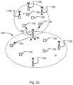
- Figure 2a illustrates one example network where the proposed precoder may be implemented.
- three base stations 110, in LTE eNodeBs are jointly transmitting to wireless devices 10 within a first device category, namely, interference mitigation capable wireless devices or UEs and to wireless devices 12 within a second device category, namely interference mitigation non-capable wireless devices or UEs.
- an interference mitigation capable wireless device or UE is a UE having multiple antennas and/or advanced receiver algorithms.
- an interference mitigation non-capable wireless device or UE is a UE with low antennas and/or does not use receiver (RX) algorithms. In LTE this mode is referred to as coherent Joint TX, which is one of the defined COMP modes in LTE.
- more than one point transmits the same data blocks to a UE simultaneously.
- the UE receives a combined version of signals from the more than one signal paths from different access points.
- the jointly transmitted signal can raise an average signal to noise plus interference ratio. As a consequence, the downlink transmission quality is improved.
- LTE is generally used herein as an example, the same principle may be used in other cellular systems where cell synchronization is performed in a group of cells, in particular in a 5G network.
- the base stations 110 are e.g. transmitting the same signal to one wireless device, from different antennas in different base stations 110a.
- a number of coordinated base stations 110 and wireless devices 10, 12 are referred to as a cluster 100.
- the transmitting side e.g. the base station or similar network side function
- the transmitting side need to know the per-physical-resource radio channel from transmission, TX, point to receiver, RX, antenna for each Transmission point and RX antenna in the network (typically called the downlink channel).
- TX transmission
- RX point to receiver
- antenna antenna for each Transmission point and RX antenna in the network
- the downlink channel typically called the downlink channel.
- the receiver of data needs to estimate the channel to be able to demodulate the data, but here, in order to avoid interference and aim right, the transmitter needs this information as well.
- the system uses the same radio channel frequency for both uplink and downlink transmissions (TDD) and that the classical channel reciprocity is usable.
- TDD uplink and downlink transmissions
- the latter means that the channel estimates for one direction can be used directly or indirectly to estimate the channel in the other direction.
- the downlink channel estimates are obtained by letting the UEs periodically or aperiodically transmit pilot (or sounding ) sequences to the transmission points which receive these sequences in order to estimate the channel.
- pilot or sounding
- multiple orthogonal pilot sequences can be transmitted at the same time by several UEs within one cluster. In this way, the network can estimate the downlink channel for all Transmission points to multiple UEs at the same time (again, assuming reciprocity). This is illustrated in figure 2b .
- the network needs to calculate a precoding for each physical resource (or group of physical resources) in order to transmit the D data streams from N TX antennas to the M RX antennas.
- the downlink channel matrix is denoted H .
- the transmitted signal vector from the N TX antennas is denoted y and the received signal vector collecting the received signals from all antennas of all users in the cluster of interest is denoted z.
- W the received signal vector
- Examples of classical precoding functions are SLNR (maximizing Signal-to-Leakage-and-Noise ratio), Zero Forcing (minimizing interference).
- Figure 2c illustrates two clusters a and b with coordinated devices.
- the devices in the cluster are enumerated using the letter of the cluster as a suffix.
- the base stations of cluster "a” are enumerated 110a and the wireless devices of cluster “a” are enumerated 10a.
- the base stations in cluster "a” are transmitting they try to cancel or at least minimize the interference caused to other wireless devices 10a, 12a within the cluster using precoding and/or beamforming.
- the inventive methods and devices herein propose a new precoder weight calculating algorithm which takes an estimate of the caused inter-cluster interference into account and tries to minimize such interference.
- wireless devices since some wireless devices have certain capabilities, functions and/or conditions, the need to transmit in their direction is not needed. These wireless devices are classified as being within one or more specific wireless device categories. As such, the inventive methods and devices herein propose a new precoder weight calculating algorithm which takes an estimate of the caused inter-cluster interference based on wireless devices within one or more wireless device category and tries to minimize such interference.
- wireless devices 10, 12 within two wireless device categories are illustrated.
- the wireless devices within each wireless device category have a common feature and/or capability.
- the common capabilty is directed toward interference mitigation capability, i.e. those wireless devices that are interference mitigation non-capable wireless devices 12a and those wireless devices that are interference mitigation capable wireless devices 10a.
- an interference mitigation capable wireless device or UE is a UE having multiple antennas and/or advanced receiver algorithms.
- an interference mitigation non-capable wireless device or UE is a UE with low antennas and/or does not use receiver (RX) algorithms.
- RX receiver
- Other constraints may include, but not limited to, subscription rate, bandwidth, VIP status, and devices that are known to be typically used for transmission of delay sensitive traffic, i.e. devices typically used for critical MTC which need ultra-reliable low latency communication.
- the cluster for example the cluster in Figure 2a-c , comprises wireless devices 10a, 12a, where wireless device 12a are interference mitigation non-capable wireless devices and wireless device 10a are interference mitigation capable wireless devices, and one or more network nodes 110a, wherein the one or more network nodes 110a are transmitting in coordination to the wireless devices 10a, 12a in the cluster using several transceiver antennas.
- the method is typically performed when network node 110a, such as an eNodeB, is about to transmit a signal to a wireless device in the cluster.
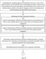
- the method comprises scheduling S1 the sounding sequences transmitted by the one or more wireless devices 10a, 12a in the cluster 100.
- the network node 110a allocates resources e.g. time and frequency for the sounding signals and also informs the wireless devices about the resources.
- the network node is responsible for all scheduling.
- other solutions are also possible, as discussed below.
- the scheduling S1 typically comprises scheduling orthogonal sounding sequences transmitted by the one or more wireless devices within each cluster 100.
- the scheduling may include reserving some of the time intervals, i.e. contrained time intervals, for only interference mitigation non-capable wireless devices 12a.
- the other time intervals i.e. uncontrained time intervals, do not have such constraints so that, if uplink wireless devices can be scheduled in those TTIs, no wireless devices are excluded from being scheduled.
- the network can estimate the downlink channel for all transmission points to multiple wireless devices based on their respective interference mitigation capabilities at the same time (again, assuming reciprocity).
- the downlink channel matrix is denoted H.
- the contrained time interval is directed toward the sounding sequences by interference mitigation non-capable wireless devices 12a. This is illustrative. Those skilled in the art will recognized that the contrained time may also be directed to additional categories of wireless devices.
- step S2 for each transceiver antenna in each of the one or more network nodes 110a, a signal is received comprising pre-defined sounding sequences transmitted by the one or more wireless devices 10a, 12a of the cluster 100 and sounding channel interference from one or more wireless devices 10b, 12b.
- Each antenna corresponds to a transmission point.
- the antennas may be located in one or several network nodes. Because the sounding signals are known to the network nodes this enables calculation of the physical channel from the network nodes' transmit antennas to the wireless devices' receive antennas for a certain resource r at a certain time t .
- the time may be referred to as a transmission time interval, TTI.
- the system estimates S4 from the received signals, the sounding channel interference from those wireless devices not associated with the particular device category.
- These estimates include two sets of inter-cluster (inter-cell) estimates, one based on the signal received during the constrained time intervals associated with the particular device category, i.e. a constrained estimate, and the second based on the signal received from during the unconstrained time intervals from all of the two or more wireless devices, i.e. an unconstrained estimate.
- the network node estimates the channel, using the known sounding sequences. By analyzing the actually received signal it is, when knowing the channel, also possible to estimate the interference and noise.
- the sounding schedule such that sounding sequences in different clusters have a correlation below a threshold. In other words, the sounding sequences are uncorrelated, or at least almost uncorrelated, between clusters. By channel analysis it may therefore be able to extract so called "pilot pollution”.
- the network node may identify the sum of the "unknown" wireless devices that are also transmitting sounding signals.
- the method further comprises determining S5 downlink precoder weights, for use when transmitting from the transceiver antennas of the cluster 100, using the estimated sounding channel interference from the one or more wireless devices 10b, 12b.
- This step implies utilizing the knowledge about possible "unknown" wireless devices in order to avoid disturbing them.
- the precoder is estimated based on the estimated channel between the transmitters and receiver of the transmission in accordance with prior art, wherein the estimated sounding channel interference is also taken into account as an additional factor, where the estimated sounding channel interference is obtained from a weighted sum of the estimates obtained from the constrained and nonconstrained estimate.
- the weighted sum of the estimates obtained from the constrained and nonconstrained estimates may be based on a tradeoff between how much interference protection should be dedicated to the constrained UE set versus to all UEs.
- the selection of proper weights, to optimize a proper performance metric, such as throughput, can be made using network simulations, or in a live network environment through manual tuning or machine learning approaches.
- the weighted sum may be calculated by multiplying both the constrained and unconstrained estimates by weighting values that equal 1. For example, a weighted sum of 70% for the constrained estimate and 30% for the unconstrained estimate would be calculated as (0.7)*constrained estimate + (0.3)*uncontrained estimate. In this example, the weighting values of 0.7 and 0.3 equal 1 when added together.
- the weighting value for the constrained estimate can range from 0 to 1, while the weighting value for the unconstrained estimate can range from 0 to 1.
- the basis for using a weighted sum is to tune how considerate to be for the category of UEs which are not seen as being the prioritized UEs for interference avoidance.
- the determining S5 implies that the precoder weights are determined such that the interference that the transmissions from the transceiver antennas will cause to the wireless devices 10b, 12b outside the cluster 100 is minimized or reduced.
- the precoder is set to optimize the channel to the receiver or receivers, while still cancelling the interference both for wireless devices inside and outside the own cluster.
- the method comprises the step of transmitting S6 data using the determined S5 precoder weights. This implies that the network node transmits data using the calculated precoder. Because the precoder was selected to consider even other cluster's wireless devices, the inter-cluster interference is reduced.
- the sounding channel interference may be estimated in different ways.
- One example embodiment is to calculate S4a sounding channel interference covariance estimates of the estimated sounding channel interference, for each of the constrained and unconstrained estimates.
- the determining S5 comprises determining S5a precoder weights based on a weighted sum of the sounding channel interference covariance constrained and unconstrained estimates. This implies that the sounding channel interference covariance is estimated and that the precoder is calculated using the sounding channel interference covariance as one input value.
- the covariance represents the spatial statistics of the intercluster interference.
- H ( r, t ) The physical channel from the eNodeB TX antennas to the UE RX antennas for a certain resource r at a certain time t is denoted H ( r, t ) and since the channel is assumed reciprocal, the channel in the reverse direction is H T ( r , t). In most of the equations below, the resource and time notation ( r, t ) is omitted for readability.
- the subscript U is used for the UE signals and matrices, and subscript E for the eNodeB signals.
- the channel H and the diagonal maximum TX gain is given by P E (which may be a complex rotation due to RX-TX phase differences)
- the channel estimate of H is denoted ⁇ .
- the channel from the cluster TX antennas to intercluster UEs i.e. UEs in other clusters
- G The channel from the cluster TX antennas to intercluster UEs (i.e. UEs in other clusters)
- G The channel from the cluster TX antennas to intercluster UEs (i.e. UEs in other clusters)
- G The channel estimates of G are not available, since the precise sounding resources of another cluster are not known by the own cluster, possibly due to slow backhaul communication between clusters.
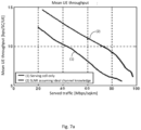
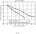
- Figure 7a illustrates simulation of throughput using a SLNR precoding algorithm with ideal channel knowledge as input and Figure 7b illustrates the same precoder with practical channel estimates as input.
- the SLNR precoding algorithm assumes that it has ideal channel knowledge.
- SLNR precoding gives nice gains for ideal channel knowledge, Figure 7a , but all gains are turned into loss, Fig. 7b , compared to the legacy serving cell transmission when practical channel estimates are used.
- the proposed technique can be extended to further comprise estimating S3, using received pre-defined sounding sequences, channel estimation error estimates corresponding to respective downlink channel estimates based on the received signal and wherein the determining S5 comprises determining S5b precoder weights based on the estimated channel estimation error estimates.
- a typical example is that the determining S5 implies that the precoder weights are selected such that, transmissions to wireless devices 10b, 12b outside the cluster 100 are reduced to a higher extent for a first signal corresponding to a first channel estimation error than for a second signal corresponding to a second channel estimation error, when the first channel estimation error corresponds to a higher channel quality than the second channel estimation error.
- the method comprises calculating S3a channel estimation error covariance estimates, and the determining S5 comprises determining S5b precoder weights based on the channel estimation error covariance estimates.
- determining S5 downlink precoder weights implies that the precoder weights are selected such that, transmissions to wireless devices outside the cluster are reduced to a higher extent for a first signal corresponding to a first channel estimation error than for a second signal corresponding to a second channel estimation error, when the first channel estimation error corresponds to a higher channel quality than the second channel estimation error.
- step S5 a few different potential embodiments of how the precoder may be determined in step S5, using a so called precoding calculation function, as well as the estimation of ⁇ H and ⁇ G are presented.
- channel estimation and inter-cluster interference channel covariance estimation follow below.
- the channel estimation and inter-cluster interference channel covariance estimation are computed separately for the sounding information obtained from the two different sounding intevals for the two different UE categories. These estimates from the two sounding intervals can then be weighted appropriately as mentioned above.
- the disclosure is not limited to this example.
- a standard channel estimation procedure is used to obtain a channel estimate ⁇ from the received samples y E on sounding resources.
- the determining S5 comprises minimizing a sum of the estimated interference for the one or more wireless devices 10b, 12b outside the cluster 100, and a difference between the resulting effective channel between the transceiver antennas and the wireless devices in the cluster and a corresponding desired effective channel.
- the determining S5 comprises maximizing a Signal to Leakage and Noise Ratio of a channel between the transceiver antennas and the wireless devices in the cluster, wherein the maximizing comprises a regularization term which is based on the sounding channel interference estimates.
- the time aspect of the estimates was omitted for clarity.
- the UL and DL transmissions do not take place in the same time instant, and therefore the coordination unit does not have the latest information on neither channel estimates nor interference covariance estimates.
- the channel estimation filtering or extrapolation to the given time from previous sounding instants is a standard procedure outside of the scope of this disclosure.
- the timing aspect of the interference covariance estimate part will now be discussed.
- the scheduling S1 comprises coordinating sounding sequence transmissions between the cluster 100 and at least one other cluster.
- the scheduling S1 comprises scheduling the sounding signals a pre-defined time before a corresponding downlink transmission.
- this could be to set a fixed sounding-to-DL-transmission time gap ⁇ DL-SRS so that the UEs scheduled for sounding at time instant t- ⁇ DL-SRS are exactly the same UEs being scheduled for DL transmission at time t in all clusters.
- More advanced ways to coordinate include if one cluster knows the pilot sounding resources of another cluster the former cluster could select among its own UEs that are likely to be significant victim UEs (based e.g. on pathgain/RSRP estimates to find out the most strongly interfered UEs) of the latter cluster's transmissions during the time period between two pilot sounding occasions for the latter cluster and let those selected UEs' pilot sounding collide with the pilot sounding of the latter cluster.
- the scheduling S1 comprises scheduling sounding sequences of at least one of the wireless devices 10a, 12a within the cluster 100 to at least partly overlap with the sounding sequences of at least one other cluster.
- the clusters' pilot sounding resources could be set up in a predetermined fashion and knowledge of that sounding pattern could be shared among multiple clusters.
- a cluster may signal another cluster the pilot sounding pattern or individual future occasions.
- the cluster comprises a single network node 110a comprising several transceiver antennas, as illustrated in Figure 6 .
- An application for MU-MIMO is obtained by setting the number of network nodes to one in the previous derivation, i.e. only one network point/node is included in the cluster. This would allow one point/node to partly also avoid transmitting towards victim UEs of neighboring nodes/points. This could also be referred to as a version of coordinated beamforming.
- Figure 4 illustrates an example coordination unit 115, according to some of the example embodiments, wherein the coordination unit 115 is configured to coordinate transmissions in a cluster comprising one or more wireless devices and one or more network nodes, wherein the one or more network nodes are transmitting in coordination to the one or more wireless devices in the cluster using several transceiver antennas.
- the inclusion of coordination unit 115 is dependant upon whether any applicable rules are to be implemented on a network wide basis or not. If such rules are to be applied network wide, then coordination unit 115 may not be utilized. In those situations where different cells within a network need different rules, coordination unit 115 may be utilized.
- the coordination unit 115 comprises processing circuitry 113 configured to receive, for each transceiver antenna in each of the one or more network nodes 110a, a signal comprising pre-defined sounding sequences transmitted by the one or more wireless devices inside the cluster and sounding channel interference from one or more wireless devices outside the cluster.
- the processing circuitry 113 is further configured to estimate, from the received signal, the sounding channel interference from the wireless devices outside the cluster.
- the processing circuitry 113 is also configured to determine downlink precoding weights, for use when transmitting from the transceiver antennas of the cluster, based on the received signal and the estimated sounding channel interference.
- the processing circuitry 113 may be any suitable type of computation unit, e.g.
- processing circuitry 113 need not be provided as a single unit but may be provided as any number of units or circuitry.
- the processing circuitry 113 may be in communication, directly or indirectly, with a radio communication interface (not shown).
- the processing circuitry 113 may be capable of executing computer program code.
- the coordination unit 115 may comprise a memory, MEM 112.
- the memory 112 may be comprised in the processing circuitry 113.
- a computer program may be stored in the memory 112. The computer program may, when run in the coordination unit 115, cause the coordination unit 115 to perform aspects of the method as disclosed above.
- the memory 112 can be any combination of a Random Access Memory, RAM, and a Read Only Memory, ROM.
- the memory 112 may comprise persistent storage, which, for example, can be any single one or combination of magnetic memory, optical memory, or solid state memory or even remotely mounted memory.
- the processing circuitry 113 comprises modules configured to perform the methods described above.
- the processing circuitry 113 comprises a receive module M1 configured to receive, for each transceiver antenna in each of the one or more network nodes 110a, a signal comprising pre-defined sounding sequences transmitted by the one or more wireless devices inside the cluster and sounding channel interference from one or more wireless devices outside the cluster.
- the processing circuitry 113 further comprises an estimation module M5 configured to estimate, from the received signal, the sounding channel interference from the wireless devices outside the cluster.
- the processing circuitry 113 also comprises a determination module M7 configured to determine downlink precoding weights, for use when transmitting from the transceiver antennas of the cluster, based on the received signal and the estimated sounding channel interference.
- the processing circuitry 113 may additionally comprise a transmit module M9 configured to transmit data using the determined precoding weights.
- the processing circuitry 113 may additionally comprise an estimation and calculation module M3 configured to estimate, using received pre-defined sounding sequences, channel estimation error estimates corresponding to respective downlink channel estimates based on the received signal, and calculate channel estimation error covariance estimates.
- the coordination unit is implemented in a computer cloud.
- the coordination unit is implemented in a software defined network, SDN.
- the processing circuitry 113 is configured to calculate sounding channel interference covariance estimates of the estimated sounding channel interference, and to determine precoding weights based on the sounding channel interference covariance estimates.
- the processing circuitry 113 is configured to estimate, using received pre-defined sounding sequences, channel estimation error estimates corresponding to respective downlink channel estimates based on the received signal and wherein the determining comprises determining precoding weights based on the estimated channel estimation error estimates.
- the processing circuitry 113 is configured to calculate channel estimation error covariance estimates, and wherein the determining comprises determining precoding weights based on the channel estimation error covariance estimates.
- determining implies that the precoding weights are selected such that, transmissions to wireless devices outside the cluster are reduced to a higher extent for a first signal corresponding to a first channel estimation error than for a second signal corresponding to a second channel estimation error, when the first channel estimation error corresponds to a higher channel quality than the second channel estimation error.
- the processing circuitry 113 is configured to schedule the sounding sequences transmitted by the one or more wireless devices in the cluster.
- the processing circuitry 113 is configured to transmit data using the determined precoding weights.
- Figure 5 illustrates an example network node 110a, according to some of the example embodiments, wherein the network node 110a is configured to coordinate transmissions in a cluster comprising one or more wireless devices and one or more network nodes 110a, wherein the one or more network nodes 110a are transmitting in coordination to the wireless devices in the cluster using several transceiver antennas.
- the network node 110a comprises an embodiment of a coordination unit as described above in relation to Fig. 3 .
- the network node 110a further comprises a communication interface 111 comprising one or more transceiver antennas, wherein the communications interface 111 is configured for communication with a wireless device.
- the communication interface 111 comprises a radio communication interface 111a and a network communication interface 111b.
- the radio communication interface 111a is configured for communication with wireless devices within reach of the network node over a radio communication technology.
- the network communication interface 111b is configured for communication with other network nodes. This communication is often wired e.g. using fiber. However, it may as well be wireless.
- the connection between network nodes is generally referred to as the backhaul.
- FIGS 8a and 8b illustrate predicted gains obtained by Multi-User Joint Transmission over traditional serving cell transmission using the present invention.
- Figure 8a illustrates a simulation of a Multi-User Joint transmission using a custom Matlab simulator using standard 3GPP Hexagonal Hetnet models extracted from the Raptor simulator.
- Figure 8b illustrates mean wireless device throughput for different served traffic conditions.
- Multi-User Joint Transmission schemes based on Minimum Mean-Square-Error Zero Forcing, MMSE ZF, where inter-cluster interference is (the present invention), legend (3), and is not, legend (2), taken into account, are compared to legacy serving cell only scheduling (the typical LTE or HSPA networks today).
- the present invention is predicted to improve the mean wireless device throughput, with the improvement increasing as the served traffic, measured in data rate per area unit, increases.
- wireless terminal or “wireless device” encompass any device which is able to communicate wirelessly with another device, as well as, optionally, with an access node of a wireless network, by transmitting and/or receiving wireless signals.
- wireless device encompasses, but is not limited to: a user equipment, e.g. an LTE UE, a mobile terminal, a stationary or mobile wireless device for machine-to-machine communication, an integrated or embedded wireless card, an externally plugged in wireless card, a dongle etc.
- user equipment is sometimes used to exemplify various embodiments.
Landscapes
- Engineering & Computer Science (AREA)
- Computer Networks & Wireless Communication (AREA)
- Signal Processing (AREA)
- Power Engineering (AREA)
- Mobile Radio Communication Systems (AREA)
Claims (15)
- Verfahren, das in einem Kommunikationsnetzwerk durchgeführt wird, zum Abschwächen von Interferenzen zwischen Clustern, wobei das Kommunikationsnetzwerk dazu konfiguriert ist, Übertragungen in einem Cluster zu koordinieren, umfassend eine oder mehrere drahtlose Vorrichtungen (10a, 12a) innerhalb von zwei drahtlosen Vorrichtungskategorien und einen oder mehrere Netzwerkknoten (110a), wobei der eine oder die mehreren Netzwerkknoten (110a) in dem Cluster in Koordinierung zu der einen oder den mehreren drahtlosen Vorrichtungen (10a, 12a) in dem Cluster unter Verwendung einer Vielzahl von Sendeempfängerantennen übertragen, wobei eine der zwei drahtlosen Vorrichtungskategorien nicht interferenzminderungsfähige drahtlose Vorrichtungen sind und eine der zwei drahtlosen Vorrichtungskategorien interferenzminderungsfähige drahtlose Vorrichtungen sind, das Verfahren umfassend:Empfangen (S2a), während eines begrenzten Zeitintervalls, für jede der Vielzahl von Sendeempfängerantennen in jedem des einen oder der mehreren Netzwerkknoten (110a) eines ersten Signals, umfassend vordefinierte Sounding-Sequenzen, die durch mindestens eine der einen oder der mehreren drahtlosen Vorrichtungen (12a) von einer ersten der zwei drahtlosen Vorrichtungskategorien übertragen werden, und Sounding-Kanalinterferenzen von einer oder mehreren drahtlosen Vorrichtungen außerhalb des Clusters;Empfangen (S2b), während eines unbegrenzten Zeitintervalls, für jede der Vielzahl von Sendeempfängerantennen in jedem des einen oder der mehreren Netzwerkknoten (110a) eines zweiten Signals, umfassend vordefinierte Sounding-Sequenzen, die durch mindestens eine der einen oder der mehreren drahtlosen Vorrichtungen (10a, 12a) des Clusters von einer beliebigen der zwei drahtlosen Vorrichtungskategorien übertragen werden, und Sounding-Kanalinterferenzen von einer oder mehreren drahtlosen Vorrichtungen außerhalb des Clusters;Schätzen (S4), von dem ersten Signal der Sounding-Kanalinterferenz, die der einen oder den mehreren drahtlosen Vorrichtungen (12a) aus der ersten drahtlosen Vorrichtungskategorie zugeordnet ist; undSchätzen (S4), von dem zweiten Signal der Sounding-Kanalinterferenz, die der einen oder den mehreren drahtlosen Vorrichtungen (10a, 12a) von einer beliebigen der zwei drahtlosen Vorrichtungskategorien zugeordnet ist; undBestimmen (S5) von Downlink-Vorcodierer-Gewichtungen, zur Verwendung beim Übertragen von den Sendeempfängerantennen, unter Verwendung des empfangenen ersten Signals und des zweiten Signals und der Schätzungen der Sounding-Kanalinterferenz.
- Verfahren nach einem der vorstehenden Ansprüche, wobei das Bestimmen (S5) der Vorcodierer-Gewichtungen so erfolgt, dass die Interferenz der Übertragungen von den Sendeempfängerantennen zu der einen oder den mehreren drahtlosen Vorrichtungen der ersten drahtlosen Vorrichtungskategorie reduziert wird, und/oder
wobei das Schätzen (S4) das Berechnen (S4a) von Sounding-Kanalinterferenz-Kovarianzschätzungen der geschätzten Sounding-Kanalinterferenz umfasst, und wobei das Bestimmen (S5) das Bestimmen (SSa) von Vorcodierer-Gewichtungen basierend auf den Sounding-Kanalinterferenz-Kovarianzschätzungen umfasst. - Verfahren nach einem der vorstehenden Ansprüche, wobei das Schätzen (S4) das Schätzen, von dem empfangenen ersten Signal, der ersten Sounding-Kanalinterferenz; und das Schätzen, von dem empfangenen zweiten Signal, der zweiten Sounding-Kanalinterferenz umfasst, und optional,
wobei das Schätzen (S4) das Berechnen (S4a) einer ersten Sounding-Kanalinterferenz-Kovarianzschätzung der ersten geschätzten Sounding-Kanalinterferenz und einer zweiten Sounding-Kanalinterferenz-Kovarianzschätzung der zweiten geschätzten Sounding-Kanalinterferenz umfasst, und wobei das Bestimmen (S5) das Bestimmen (SSa) von Vorcodierer-Gewichtungen basierend auf einer gewichteten Summe der ersten und der zweiten Sounding-Kanalinterferenz-Kovarianzschätzung umfasst. - Verfahren nach einem der vorstehenden Ansprüche, wobei das Verfahren Folgendes umfasst: Schätzen (S3), unter Verwendung von empfangenen vordefinierten Sounding-Sequenzen, von Kanalschätzungs-Fehlerschätzungen, die jeweiligen Downlink-Kanalschätzungen basierend auf dem empfangenen ersten Signal und dem empfangenen zweiten Signal entsprechen, und wobei das Bestimmen (S5) das Bestimmen (SSb) von Vorcodierer-Gewichtungen basierend auf den geschätzten Kanalschätzungs-Fehlerschätzungen umfasst.
- Verfahren nach Anspruch 4, wobei das Verfahren das Berechnen (S3a) von Kanalschätzungsfehler-Kovarianzschätzungen umfasst, und wobei das Bestimmen (S5) das Bestimmen (SSb) von Vorcodierer-Gewichtungen basierend auf den Kanalschätzungsfehler-Kovarianzschätzungen umfasst und/oder
wobei das Bestimmen (S5) impliziert, dass die Vorcodierer-Gewichtungen so ausgewählt werden, dass Übertragungen zu drahtlosen Vorrichtungen (10b) außerhalb des Clusters (100) in einem höheren Maß für ein erstes Signal, das einem ersten Kanalschätzungsfehler entspricht, minimiert werden als für ein zweites Signal, das einem zweiten Kanalschätzungsfehler entspricht, wenn der erste Kanalschätzungsfehler einer höheren Kanalqualität entspricht als der zweite Kanalschätzungsfehler. - Verfahren nach einem der vorstehenden Ansprüche, wobei das Bestimmen (S5) das Maximieren eines Signal-Verlust- und Rausch-Verhältnisses eines Kanals zwischen den Sendeempfängerantennen und den drahtlosen Vorrichtungen in dem Cluster umfasst, wobei das Maximieren einen Regularisierungsterm umfasst, der auf den Sounding-Kanal-Interferenzschätzungen basiert und/oder
wobei das Verfahren in einer Koordinierungseinheit in dem Kommunikationsnetzwerk durchgeführt wird. - Koordinierungseinheit (115), die dazu konfiguriert ist, Übertragungen in einem Cluster zu koordinieren, umfassend eine oder mehrere drahtlose Vorrichtungen innerhalb von zwei drahtlosen Vorrichtungskategorien und einen oder mehrere Netzwerkknoten, wobei der eine oder die mehreren Netzwerkknoten in dem Cluster in Koordinierung zu den drahtlosen Vorrichtungen in dem Cluster unter Verwendung mehrerer Sendeempfängerantennen übertragen, wobei eine der zwei drahtlosen Vorrichtungskategorien nicht interferenzminderungsfähige drahtlose Vorrichtungen sind und eine der zwei drahtlosen Vorrichtungskategorien interferenzminderungsfähige drahtlose Vorrichtungen sind, wobei die Koordinierungseinheit (115) Folgendes umfasst:
eine Verarbeitungsschaltung (113), die konfiguriert ist zum:Empfangen, während eines begrenzten Zeitintervalls, für jede der Vielzahl von Sendeempfängerantennen in jedem des einen oder der mehreren Netzwerkknoten (110a) eines ersten Signals, umfassend vordefinierte Sounding-Sequenzen, die durch mindestens eine der einen oder der mehreren drahtlosen Vorrichtungen (12a) von einer ersten der zwei drahtlosen Vorrichtungskategorien übertragen werden, und Sounding-Kanalinterferenzen von einer oder mehreren drahtlosen Vorrichtungen außerhalb des Clusters;Empfangen, während eines unbegrenzten Zeitintervalls, für jede der Vielzahl von Sendeempfängerantennen in jedem des einen oder der mehreren Netzwerkknoten (110a) eines zweiten Signals, umfassend vordefinierte Sounding-Sequenzen, die durch mindestens eine der einen oder der mehreren drahtlosen Vorrichtungen (10a, 12a) des Clusters von einer beliebigen der zwei drahtlosen Vorrichtungskategorien übertragen werden, und Sounding-Kanalinterferenzen von einer oder mehreren drahtlosen Vorrichtungen außerhalb des Clusters;Schätzen, von dem ersten Signal der Sounding-Kanalinterferenz, die der einen oder den mehreren drahtlosen Vorrichtungen (12a) aus der ersten drahtlosen Vorrichtungskategorie zugeordnet ist; und
Schätzen, von dem zweiten Signal, der Sounding-Kanalinterferenz, die der einen oder den mehreren drahtlosen Vorrichtungen (10a, 12a) einer beliebigen der zwei drahtlosen Vorrichtungskategorien zugeordnet ist; undBestimmen von Downlink-Vorcodierer-Gewichtungen, zur Verwendung beim Übertragen von den Sendeempfängerantennen, unter Verwendung des empfangenen ersten Signals und des zweiten Signals und der geschätzten Sounding-Kanalinterferenz. - Koordinierungseinheit (115) nach Anspruch 7, wobei die Verarbeitungsschaltung (113) dazu konfiguriert ist, die Vorcodierer-Gewichtungen so zu bestimmen, dass die Interferenz der Übertragungen von den Sendeempfängerantennen zu der einen oder den mehreren drahtlosen Vorrichtungen von der ersten drahtlosen Vorrichtungskategorie reduziert wird, und/oder
wobei die Verarbeitungsschaltung (113) dazu konfiguriert ist, Sounding-Kanalinterferenz-Kovarianzschätzungen der geschätzten Sounding-Kanalinterferenz zu berechnen, und wobei das Bestimmen (S5) das Bestimmen (S5a) von Vorcodierer-Gewichtungen basierend auf den Sounding-Kanalinterferenz-Kovarianzschätzungen umfasst. - Koordinierungseinheit (115) nach einem der Ansprüche 7-8, wobei die Verarbeitungsschaltung (113) dazu konfiguriert ist, aus dem empfangenen ersten Signal die erste Sounding-Kanalinterferenz zu schätzen; und
Schätzen, von dem empfangenen zweiten Signal, der zweiten Sounding-Kanalinterferenz und, optional,
wobei die Verarbeitungsschaltung (113) dazu konfiguriert ist, eine erste Sounding-Kanalinterferenz-Kovarianzschätzung der ersten geschätzten Sounding-Kanalinterferenz und eine zweite Sounding-Kanalinterferenz-Kovarianzschätzung der zweiten geschätzten Sounding-Kanalinterferenz zu berechnen (S4a), und wobei das Bestimmen (S5) das Bestimmen (S5a) von Vorcodierer-Gewichtungen basierend auf einer gewichteten Summe der ersten und der zweiten Sounding-Kanalinterferenz-Kovarianzschätzung umfasst. - Koordinierungseinheit (115) nach einem der Ansprüche 7-9, wobei die Verarbeitungsschaltung (113) konfiguriert ist zumSchätzen, unter Verwendung von empfangenen vordefinierten Sounding-Sequenzen, von Kanalschätzungs-Fehlerschätzungen, die jeweiligen Downlink-Kanalschätzungen basierend auf dem empfangenen ersten Signal und dem empfangenen zweiten Signal entsprechen, und wobei das Bestimmen (S5) das Bestimmen (S5b) von Vorcodierer-Gewichtungen basierend auf den geschätzten Kanalschätzungs-Fehlerschätzungen umfasst, und optional,wobei die Verarbeitungsschaltung (113) dazu konfiguriert ist, Kanalschätzungsfehler-Kovarianzschätzungen zu berechnen, und wobei das Bestimmen (S5) das Bestimmen (S5b) von Vorcodierer-Gewichtungen basierend auf den Kanalschätzungsfehler-Kovarianzschätzungen umfasst.
- Koordinierungseinheit (115) nach einem der Ansprüche 7-10, wobei die Verarbeitungsschaltung (113) dazu konfiguriert ist, Daten unter Verwendung der bestimmten (S5) Vorcodierer-Gewichtungen zu übertragen.
- Koordinierungseinheit (115) nach Anspruch 7-11, wobei die Verarbeitungsschaltung (113) dazu konfiguriert ist, die von der mindestens einen der einen oder mehreren drahtlosen Vorrichtungen von einer ersten der zwei oder mehreren drahtlosen Vorrichtungskategorien übertragenen Sounding-Sequenzen und die von mindestens einer der einen oder mehreren drahtlosen Vorrichtungen von einer beliebigen der zwei oder mehreren drahtlosen Vorrichtungskategorien übertragenen Sounding-Sequenzen zu planen.
- Koordinierungseinheit (115) nach Anspruch 12, wobei die Verarbeitungsschaltung (113) dazu konfiguriert ist, Sounding-Sequenzen von mindestens einer der drahtlosen Vorrichtungen (10a, 12a) innerhalb des Clusters (100) so zu planen, dass sie sich zumindest teilweise mit den Sounding-Sequenzen von mindestens einem anderen Cluster überschneiden, und/oderwobei die Verarbeitungsschaltung (113) dazu konfiguriert ist, die Sounding-Signale eine vordefinierte Zeit vor einer entsprechenden Downlink-Übertragung zu planen, und/oderwobei die Verarbeitungsschaltung (113) dazu konfiguriert ist, orthogonale Sounding-Sequenzen innerhalb jedes Clusters (100) zu planen, und/oderwobei die Verarbeitungsschaltung (113) dazu konfiguriert ist, Sounding-Sequenzen in verschiedenen Clustern so zu planen, dass sie eine Korrelation unterhalb eines Schwellenwerts aufweisen.
- Netzwerkknoten (110a), der dazu konfiguriert ist, Übertragungen in einem Cluster zu koordinieren, der zwei oder mehrere drahtlose Vorrichtungen und einen oder mehrere Netzwerkknoten (110a) umfasst, wobei der eine oder die mehreren Netzwerkknoten (110a) in Koordination zu den drahtlosen Vorrichtungen in dem Cluster unter Verwendung mehrerer Sendeempfängerantennen übertragen, wobei der Netzwerkknoten (110a)Folgendes umfasst:eine Kommunikationsschnittstelle (111), umfassend eine oder mehrere Sendeempfängerantennen, wobei die Kommunikationsschnittstelle (111) für die Kommunikation mit einer drahtlosen Vorrichtung konfiguriert ist, undeine Koordinierungseinheit (115) nach einem der Ansprüche 7 bis 13.
- Computerlesbares Medium, mit einem darauf gespeicherten Computerprogramm, das, bei Ausführung in einer Koordinierungseinheit, die Koordinierungseinheit dazu veranlasst, das Verfahren wie nach einem der Ansprüche 1-6 offenbart durchzuführen.
Applications Claiming Priority (1)
| Application Number | Priority Date | Filing Date | Title |
|---|---|---|---|
| PCT/IB2018/057376 WO2020065370A1 (en) | 2018-09-24 | 2018-09-24 | Uplink and downlink reciprocity management of interference |
Publications (2)
| Publication Number | Publication Date |
|---|---|
| EP3857724A1 EP3857724A1 (de) | 2021-08-04 |
| EP3857724B1 true EP3857724B1 (de) | 2024-02-07 |
Family
ID=63915322
Family Applications (1)
| Application Number | Title | Priority Date | Filing Date |
|---|---|---|---|
| EP18789698.0A Active EP3857724B1 (de) | 2018-09-24 | 2018-09-24 | Uplink- und downlink-reziprozitätsverwaltung von interferenz |
Country Status (4)
| Country | Link |
|---|---|
| US (1) | US11411621B2 (de) |
| EP (1) | EP3857724B1 (de) |
| CN (1) | CN113016150B (de) |
| WO (1) | WO2020065370A1 (de) |
Families Citing this family (8)
| Publication number | Priority date | Publication date | Assignee | Title |
|---|---|---|---|---|
| EP4091257A4 (de) * | 2020-01-14 | 2023-09-20 | Nokia Solutions and Networks Oy | Downlink-strahlformung in einem mu-mimo-system |
| WO2022110087A1 (zh) * | 2020-11-28 | 2022-06-02 | 华为技术有限公司 | 一种通信方法、装置及计算机可读存储介质 |
| WO2023274538A1 (en) * | 2021-07-01 | 2023-01-05 | Telefonaktiebolaget Lm Ericsson (Publ) | A method for determining receiver weights |
| WO2023101578A1 (en) * | 2021-11-30 | 2023-06-08 | Telefonaktiebolaget Lm Ericsson (Publ) | Interference suppression in a wireless communication network |
| CN114466364B (zh) * | 2021-12-31 | 2025-08-15 | 华为技术有限公司 | 通信方法、装置、系统及存储介质 |
| CN119256497A (zh) * | 2022-07-12 | 2025-01-03 | 瑞典爱立信有限公司 | 经由特征波束成形的互易性辅助干扰抑制 |
| EP4616541A1 (de) * | 2022-11-07 | 2025-09-17 | Telefonaktiebolaget LM Ericsson (publ) | Verfahren zur auswahl eines precoders auf der basis von gemessener srs-interferenz auf srs, die von downlink-benutzervorrichtungen mit schwerem verkehr übertragen werden |
| WO2025174282A1 (en) * | 2024-02-15 | 2025-08-21 | Telefonaktiebolaget Lm Ericsson (Publ) | Method and network node for handling intercell interference |
Family Cites Families (7)
| Publication number | Priority date | Publication date | Assignee | Title |
|---|---|---|---|---|
| CN101374034B (zh) * | 2007-08-20 | 2012-06-13 | 中兴通讯股份有限公司 | 下行与上行多用户多输入多输出的预编码方法 |
| KR102109655B1 (ko) | 2012-02-23 | 2020-05-12 | 한국전자통신연구원 | 대규모 안테나 시스템에서의 다중 입력 다중 출력 통신 방법 |
| CN103871888B (zh) | 2012-12-18 | 2017-09-29 | 中芯国际集成电路制造(上海)有限公司 | 半导体器件及其形成方法 |
| EP2966885B1 (de) * | 2013-03-06 | 2019-07-31 | Sharp Kabushiki Kaisha | Endgerät, basisstationsvorrichtung, kommunikationssystem, empfangsverfahren, übertragungsverfahren und kommunikationsverfahren |
| US9456360B2 (en) * | 2013-08-06 | 2016-09-27 | Universitat Politecnica De Catalunya | Method and systems for decentralized interference management in a multi-antenna wireless communication system |
| EP3275089A1 (de) * | 2015-03-27 | 2018-01-31 | Telefonaktiebolaget LM Ericsson (publ) | Verfahren und anordnungen zur minderung von inter-cluster-interferenz |
| US10404347B2 (en) * | 2016-07-13 | 2019-09-03 | Qualcomm Incorporated | Beamforming in TDD MIMO systems with asymmetric antenna configuration |
-
2018
- 2018-09-24 WO PCT/IB2018/057376 patent/WO2020065370A1/en not_active Ceased
- 2018-09-24 CN CN201880099730.8A patent/CN113016150B/zh active Active
- 2018-09-24 US US17/274,326 patent/US11411621B2/en active Active
- 2018-09-24 EP EP18789698.0A patent/EP3857724B1/de active Active
Also Published As
| Publication number | Publication date |
|---|---|
| WO2020065370A1 (en) | 2020-04-02 |
| US11411621B2 (en) | 2022-08-09 |
| EP3857724A1 (de) | 2021-08-04 |
| CN113016150A (zh) | 2021-06-22 |
| CN113016150B (zh) | 2024-10-01 |
| US20210320693A1 (en) | 2021-10-14 |
Similar Documents
| Publication | Publication Date | Title |
|---|---|---|
| EP3857724B1 (de) | Uplink- und downlink-reziprozitätsverwaltung von interferenz | |
| US10476621B2 (en) | Methods and arrangements for mitigating inter-cluster interference | |
| US11451274B2 (en) | Adaptive downlink multi user multiple input multiple output (MU-MIMO)precoding using uplink signal subspace tracking for active antenna systems AAS | |
| EP2836039B1 (de) | Drahtloses mimo-kommunikationssystem, übertragungsverfahren und vorrichtung | |
| US9407343B2 (en) | Method and apparatus for mitigating downlink interference | |
| EP2182649B1 (de) | Verfahren und vorrichtung zum entfernen von störungen zwischen von mehreren mobilstationen empfangenen signalen | |
| US9948369B2 (en) | Method and apparatus for implementing transparent multi-user multiple-input multiple-output transmission | |
| EP2329606B1 (de) | Interferenzunterdrückung durch signalkombination für mehrbenutzer-mimo-datenübertragungssystem | |
| EP2710753B1 (de) | Ul-comp-empfänger mit reduzierter komplexität | |
| US9148208B2 (en) | Antenna selection codebook for full dimensional MIMO systems | |
| CN103312390B (zh) | 基于干扰对齐的预编码方法,发射机和设备 | |
| JP2013059028A (ja) | 干渉アラインメントに基づくプレコーディング、プレデコーディング方法および送信機ならびに移動端末 | |
| WO2015070804A1 (en) | Large-scale fading coefficient estimation in wireless massive mimo systems | |
| US12231265B2 (en) | Methods and apparatus for channel estimation and precoding with incomplete channel observation and channel state information feedback | |
| CN106341168B (zh) | 预编码方法、信息发送方法、及其装置 | |
| EP2858448B1 (de) | Benutzergerät und verfahren zur anpassung des interferenzkanalcodeworts in koordiniertem interzellen-system mit mehreren antennen | |
| Salh et al. | Mitigated pilot contamination to achieve higher downlink data rate in 5G massive MIMO systems | |
| KR101384869B1 (ko) | 다중 안테나를 이용한 수신기 및 데이터 복원 방법 | |
| CN104247292B (zh) | 联合传送和接收过程 | |
| Salh et al. | Reduction Pilot Contamination in Downlink Multi-Cell for Massive MIMO Systems | |
| Apelfröjd et al. | Coded Reference Signals for Massive MIMO Channel Estimation in FDD Systems | |
| Salh et al. | Analyze of pilot reuse with achievable sum rate for massive MIMO cellular uplink | |
| Hwang | Multicell coordination with multiple receive antennas | |
| Tervo | Effective channel state acquisition in multi-cell multi-user MIMO system |
Legal Events
| Date | Code | Title | Description |
|---|---|---|---|
| STAA | Information on the status of an ep patent application or granted ep patent |
Free format text: STATUS: UNKNOWN |
|
| STAA | Information on the status of an ep patent application or granted ep patent |
Free format text: STATUS: THE INTERNATIONAL PUBLICATION HAS BEEN MADE |
|
| PUAI | Public reference made under article 153(3) epc to a published international application that has entered the european phase |
Free format text: ORIGINAL CODE: 0009012 |
|
| STAA | Information on the status of an ep patent application or granted ep patent |
Free format text: STATUS: REQUEST FOR EXAMINATION WAS MADE |
|
| 17P | Request for examination filed |
Effective date: 20210324 |
|
| AK | Designated contracting states |
Kind code of ref document: A1 Designated state(s): AL AT BE BG CH CY CZ DE DK EE ES FI FR GB GR HR HU IE IS IT LI LT LU LV MC MK MT NL NO PL PT RO RS SE SI SK SM TR |
|
| DAV | Request for validation of the european patent (deleted) | ||
| DAX | Request for extension of the european patent (deleted) | ||
| RIC1 | Information provided on ipc code assigned before grant |
Ipc: H04L 25/02 20060101ALI20230804BHEP Ipc: H04L 25/03 20060101ALI20230804BHEP Ipc: H04J 11/00 20060101ALI20230804BHEP Ipc: H04B 7/0456 20170101ALI20230804BHEP Ipc: H04B 7/06 20060101AFI20230804BHEP |
|
| GRAP | Despatch of communication of intention to grant a patent |
Free format text: ORIGINAL CODE: EPIDOSNIGR1 |
|
| STAA | Information on the status of an ep patent application or granted ep patent |
Free format text: STATUS: GRANT OF PATENT IS INTENDED |
|
| INTG | Intention to grant announced |
Effective date: 20230925 |
|
| GRAS | Grant fee paid |
Free format text: ORIGINAL CODE: EPIDOSNIGR3 |
|
| GRAA | (expected) grant |
Free format text: ORIGINAL CODE: 0009210 |
|
| STAA | Information on the status of an ep patent application or granted ep patent |
Free format text: STATUS: THE PATENT HAS BEEN GRANTED |
|
| AK | Designated contracting states |
Kind code of ref document: B1 Designated state(s): AL AT BE BG CH CY CZ DE DK EE ES FI FR GB GR HR HU IE IS IT LI LT LU LV MC MK MT NL NO PL PT RO RS SE SI SK SM TR |
|
| REG | Reference to a national code |
Ref country code: GB Ref legal event code: FG4D |
|
| REG | Reference to a national code |
Ref country code: CH Ref legal event code: EP |
|
| REG | Reference to a national code |
Ref country code: DE Ref legal event code: R096 Ref document number: 602018064964 Country of ref document: DE |
|
| REG | Reference to a national code |
Ref country code: IE Ref legal event code: FG4D |
|
| REG | Reference to a national code |
Ref country code: LT Ref legal event code: MG9D |
|
| PG25 | Lapsed in a contracting state [announced via postgrant information from national office to epo] |
Ref country code: IS Free format text: LAPSE BECAUSE OF FAILURE TO SUBMIT A TRANSLATION OF THE DESCRIPTION OR TO PAY THE FEE WITHIN THE PRESCRIBED TIME-LIMIT Effective date: 20240607 |
|
| PG25 | Lapsed in a contracting state [announced via postgrant information from national office to epo] |
Ref country code: LT Free format text: LAPSE BECAUSE OF FAILURE TO SUBMIT A TRANSLATION OF THE DESCRIPTION OR TO PAY THE FEE WITHIN THE PRESCRIBED TIME-LIMIT Effective date: 20240207 |
|
| PG25 | Lapsed in a contracting state [announced via postgrant information from national office to epo] |
Ref country code: GR Free format text: LAPSE BECAUSE OF FAILURE TO SUBMIT A TRANSLATION OF THE DESCRIPTION OR TO PAY THE FEE WITHIN THE PRESCRIBED TIME-LIMIT Effective date: 20240508 |
|
| REG | Reference to a national code |
Ref country code: AT Ref legal event code: MK05 Ref document number: 1656019 Country of ref document: AT Kind code of ref document: T Effective date: 20240207 |
|
| PG25 | Lapsed in a contracting state [announced via postgrant information from national office to epo] |
Ref country code: HR Free format text: LAPSE BECAUSE OF FAILURE TO SUBMIT A TRANSLATION OF THE DESCRIPTION OR TO PAY THE FEE WITHIN THE PRESCRIBED TIME-LIMIT Effective date: 20240207 Ref country code: NL Free format text: LAPSE BECAUSE OF FAILURE TO SUBMIT A TRANSLATION OF THE DESCRIPTION OR TO PAY THE FEE WITHIN THE PRESCRIBED TIME-LIMIT Effective date: 20240207 |
|
| PG25 | Lapsed in a contracting state [announced via postgrant information from national office to epo] |
Ref country code: ES Free format text: LAPSE BECAUSE OF FAILURE TO SUBMIT A TRANSLATION OF THE DESCRIPTION OR TO PAY THE FEE WITHIN THE PRESCRIBED TIME-LIMIT Effective date: 20240207 |
|
| PG25 | Lapsed in a contracting state [announced via postgrant information from national office to epo] |
Ref country code: AT Free format text: LAPSE BECAUSE OF FAILURE TO SUBMIT A TRANSLATION OF THE DESCRIPTION OR TO PAY THE FEE WITHIN THE PRESCRIBED TIME-LIMIT Effective date: 20240207 |
|
| PG25 | Lapsed in a contracting state [announced via postgrant information from national office to epo] |
Ref country code: NO Free format text: LAPSE BECAUSE OF FAILURE TO SUBMIT A TRANSLATION OF THE DESCRIPTION OR TO PAY THE FEE WITHIN THE PRESCRIBED TIME-LIMIT Effective date: 20240507 Ref country code: NL Free format text: LAPSE BECAUSE OF FAILURE TO SUBMIT A TRANSLATION OF THE DESCRIPTION OR TO PAY THE FEE WITHIN THE PRESCRIBED TIME-LIMIT Effective date: 20240207 Ref country code: LT Free format text: LAPSE BECAUSE OF FAILURE TO SUBMIT A TRANSLATION OF THE DESCRIPTION OR TO PAY THE FEE WITHIN THE PRESCRIBED TIME-LIMIT Effective date: 20240207 Ref country code: IS Free format text: LAPSE BECAUSE OF FAILURE TO SUBMIT A TRANSLATION OF THE DESCRIPTION OR TO PAY THE FEE WITHIN THE PRESCRIBED TIME-LIMIT Effective date: 20240607 Ref country code: HR Free format text: LAPSE BECAUSE OF FAILURE TO SUBMIT A TRANSLATION OF THE DESCRIPTION OR TO PAY THE FEE WITHIN THE PRESCRIBED TIME-LIMIT Effective date: 20240207 Ref country code: GR Free format text: LAPSE BECAUSE OF FAILURE TO SUBMIT A TRANSLATION OF THE DESCRIPTION OR TO PAY THE FEE WITHIN THE PRESCRIBED TIME-LIMIT Effective date: 20240508 Ref country code: FI Free format text: LAPSE BECAUSE OF FAILURE TO SUBMIT A TRANSLATION OF THE DESCRIPTION OR TO PAY THE FEE WITHIN THE PRESCRIBED TIME-LIMIT Effective date: 20240207 Ref country code: ES Free format text: LAPSE BECAUSE OF FAILURE TO SUBMIT A TRANSLATION OF THE DESCRIPTION OR TO PAY THE FEE WITHIN THE PRESCRIBED TIME-LIMIT Effective date: 20240207 Ref country code: BG Free format text: LAPSE BECAUSE OF FAILURE TO SUBMIT A TRANSLATION OF THE DESCRIPTION OR TO PAY THE FEE WITHIN THE PRESCRIBED TIME-LIMIT Effective date: 20240207 Ref country code: AT Free format text: LAPSE BECAUSE OF FAILURE TO SUBMIT A TRANSLATION OF THE DESCRIPTION OR TO PAY THE FEE WITHIN THE PRESCRIBED TIME-LIMIT Effective date: 20240207 |
|
| PG25 | Lapsed in a contracting state [announced via postgrant information from national office to epo] |
Ref country code: PL Free format text: LAPSE BECAUSE OF FAILURE TO SUBMIT A TRANSLATION OF THE DESCRIPTION OR TO PAY THE FEE WITHIN THE PRESCRIBED TIME-LIMIT Effective date: 20240207 Ref country code: PT Free format text: LAPSE BECAUSE OF FAILURE TO SUBMIT A TRANSLATION OF THE DESCRIPTION OR TO PAY THE FEE WITHIN THE PRESCRIBED TIME-LIMIT Effective date: 20240607 |
|
| PG25 | Lapsed in a contracting state [announced via postgrant information from national office to epo] |
Ref country code: SE Free format text: LAPSE BECAUSE OF FAILURE TO SUBMIT A TRANSLATION OF THE DESCRIPTION OR TO PAY THE FEE WITHIN THE PRESCRIBED TIME-LIMIT Effective date: 20240207 Ref country code: PT Free format text: LAPSE BECAUSE OF FAILURE TO SUBMIT A TRANSLATION OF THE DESCRIPTION OR TO PAY THE FEE WITHIN THE PRESCRIBED TIME-LIMIT Effective date: 20240607 Ref country code: PL Free format text: LAPSE BECAUSE OF FAILURE TO SUBMIT A TRANSLATION OF THE DESCRIPTION OR TO PAY THE FEE WITHIN THE PRESCRIBED TIME-LIMIT Effective date: 20240207 Ref country code: LV Free format text: LAPSE BECAUSE OF FAILURE TO SUBMIT A TRANSLATION OF THE DESCRIPTION OR TO PAY THE FEE WITHIN THE PRESCRIBED TIME-LIMIT Effective date: 20240207 |
|
| PG25 | Lapsed in a contracting state [announced via postgrant information from national office to epo] |
Ref country code: DK Free format text: LAPSE BECAUSE OF FAILURE TO SUBMIT A TRANSLATION OF THE DESCRIPTION OR TO PAY THE FEE WITHIN THE PRESCRIBED TIME-LIMIT Effective date: 20240207 |
|
| PG25 | Lapsed in a contracting state [announced via postgrant information from national office to epo] |
Ref country code: SM Free format text: LAPSE BECAUSE OF FAILURE TO SUBMIT A TRANSLATION OF THE DESCRIPTION OR TO PAY THE FEE WITHIN THE PRESCRIBED TIME-LIMIT Effective date: 20240207 |
|
| PG25 | Lapsed in a contracting state [announced via postgrant information from national office to epo] |
Ref country code: CZ Free format text: LAPSE BECAUSE OF FAILURE TO SUBMIT A TRANSLATION OF THE DESCRIPTION OR TO PAY THE FEE WITHIN THE PRESCRIBED TIME-LIMIT Effective date: 20240207 Ref country code: EE Free format text: LAPSE BECAUSE OF FAILURE TO SUBMIT A TRANSLATION OF THE DESCRIPTION OR TO PAY THE FEE WITHIN THE PRESCRIBED TIME-LIMIT Effective date: 20240207 |
|
| PG25 | Lapsed in a contracting state [announced via postgrant information from national office to epo] |
Ref country code: SK Free format text: LAPSE BECAUSE OF FAILURE TO SUBMIT A TRANSLATION OF THE DESCRIPTION OR TO PAY THE FEE WITHIN THE PRESCRIBED TIME-LIMIT Effective date: 20240207 |
|
| PG25 | Lapsed in a contracting state [announced via postgrant information from national office to epo] |
Ref country code: SM Free format text: LAPSE BECAUSE OF FAILURE TO SUBMIT A TRANSLATION OF THE DESCRIPTION OR TO PAY THE FEE WITHIN THE PRESCRIBED TIME-LIMIT Effective date: 20240207 Ref country code: SK Free format text: LAPSE BECAUSE OF FAILURE TO SUBMIT A TRANSLATION OF THE DESCRIPTION OR TO PAY THE FEE WITHIN THE PRESCRIBED TIME-LIMIT Effective date: 20240207 Ref country code: RO Free format text: LAPSE BECAUSE OF FAILURE TO SUBMIT A TRANSLATION OF THE DESCRIPTION OR TO PAY THE FEE WITHIN THE PRESCRIBED TIME-LIMIT Effective date: 20240207 Ref country code: EE Free format text: LAPSE BECAUSE OF FAILURE TO SUBMIT A TRANSLATION OF THE DESCRIPTION OR TO PAY THE FEE WITHIN THE PRESCRIBED TIME-LIMIT Effective date: 20240207 Ref country code: DK Free format text: LAPSE BECAUSE OF FAILURE TO SUBMIT A TRANSLATION OF THE DESCRIPTION OR TO PAY THE FEE WITHIN THE PRESCRIBED TIME-LIMIT Effective date: 20240207 Ref country code: CZ Free format text: LAPSE BECAUSE OF FAILURE TO SUBMIT A TRANSLATION OF THE DESCRIPTION OR TO PAY THE FEE WITHIN THE PRESCRIBED TIME-LIMIT Effective date: 20240207 |
|
| REG | Reference to a national code |
Ref country code: DE Ref legal event code: R097 Ref document number: 602018064964 Country of ref document: DE |
|
| PG25 | Lapsed in a contracting state [announced via postgrant information from national office to epo] |
Ref country code: IT Free format text: LAPSE BECAUSE OF FAILURE TO SUBMIT A TRANSLATION OF THE DESCRIPTION OR TO PAY THE FEE WITHIN THE PRESCRIBED TIME-LIMIT Effective date: 20240207 |
|
| PLBE | No opposition filed within time limit |
Free format text: ORIGINAL CODE: 0009261 |
|
| STAA | Information on the status of an ep patent application or granted ep patent |
Free format text: STATUS: NO OPPOSITION FILED WITHIN TIME LIMIT |
|
| PG25 | Lapsed in a contracting state [announced via postgrant information from national office to epo] |
Ref country code: IT Free format text: LAPSE BECAUSE OF FAILURE TO SUBMIT A TRANSLATION OF THE DESCRIPTION OR TO PAY THE FEE WITHIN THE PRESCRIBED TIME-LIMIT Effective date: 20240207 |
|
| 26N | No opposition filed |
Effective date: 20241108 |
|
| PG25 | Lapsed in a contracting state [announced via postgrant information from national office to epo] |
Ref country code: MC Free format text: LAPSE BECAUSE OF FAILURE TO SUBMIT A TRANSLATION OF THE DESCRIPTION OR TO PAY THE FEE WITHIN THE PRESCRIBED TIME-LIMIT Effective date: 20240207 Ref country code: SI Free format text: LAPSE BECAUSE OF FAILURE TO SUBMIT A TRANSLATION OF THE DESCRIPTION OR TO PAY THE FEE WITHIN THE PRESCRIBED TIME-LIMIT Effective date: 20240207 |
|
| REG | Reference to a national code |
Ref country code: CH Ref legal event code: PL |
|
| PG25 | Lapsed in a contracting state [announced via postgrant information from national office to epo] |
Ref country code: LU Free format text: LAPSE BECAUSE OF NON-PAYMENT OF DUE FEES Effective date: 20240924 |
|
| PG25 | Lapsed in a contracting state [announced via postgrant information from national office to epo] |
Ref country code: RS Free format text: LAPSE BECAUSE OF FAILURE TO SUBMIT A TRANSLATION OF THE DESCRIPTION OR TO PAY THE FEE WITHIN THE PRESCRIBED TIME-LIMIT Effective date: 20240207 |
|
| REG | Reference to a national code |
Ref country code: BE Ref legal event code: MM Effective date: 20240930 |
|
| PG25 | Lapsed in a contracting state [announced via postgrant information from national office to epo] |
Ref country code: BE Free format text: LAPSE BECAUSE OF NON-PAYMENT OF DUE FEES Effective date: 20240930 |
|
| PG25 | Lapsed in a contracting state [announced via postgrant information from national office to epo] |
Ref country code: FR Free format text: LAPSE BECAUSE OF NON-PAYMENT OF DUE FEES Effective date: 20240930 |
|
| PG25 | Lapsed in a contracting state [announced via postgrant information from national office to epo] |
Ref country code: CH Free format text: LAPSE BECAUSE OF NON-PAYMENT OF DUE FEES Effective date: 20240930 |
|
| PG25 | Lapsed in a contracting state [announced via postgrant information from national office to epo] |
Ref country code: IE Free format text: LAPSE BECAUSE OF NON-PAYMENT OF DUE FEES Effective date: 20240924 |
|
| PGFP | Annual fee paid to national office [announced via postgrant information from national office to epo] |
Ref country code: DE Payment date: 20250929 Year of fee payment: 8 |
|
| PGFP | Annual fee paid to national office [announced via postgrant information from national office to epo] |
Ref country code: GB Payment date: 20250929 Year of fee payment: 8 |
|
| PG25 | Lapsed in a contracting state [announced via postgrant information from national office to epo] |
Ref country code: CY Free format text: LAPSE BECAUSE OF FAILURE TO SUBMIT A TRANSLATION OF THE DESCRIPTION OR TO PAY THE FEE WITHIN THE PRESCRIBED TIME-LIMIT; INVALID AB INITIO Effective date: 20180924 |
|
| PG25 | Lapsed in a contracting state [announced via postgrant information from national office to epo] |
Ref country code: HU Free format text: LAPSE BECAUSE OF FAILURE TO SUBMIT A TRANSLATION OF THE DESCRIPTION OR TO PAY THE FEE WITHIN THE PRESCRIBED TIME-LIMIT; INVALID AB INITIO Effective date: 20180924 |