EP3857818B1 - Auto-optimisation de réseau radio basée sur des données provenant d'un réseau radio et de capteurs spatiotemporels - Google Patents
Auto-optimisation de réseau radio basée sur des données provenant d'un réseau radio et de capteurs spatiotemporels Download PDFInfo
- Publication number
- EP3857818B1 EP3857818B1 EP18782025.3A EP18782025A EP3857818B1 EP 3857818 B1 EP3857818 B1 EP 3857818B1 EP 18782025 A EP18782025 A EP 18782025A EP 3857818 B1 EP3857818 B1 EP 3857818B1
- Authority
- EP
- European Patent Office
- Prior art keywords
- radio network
- data samples
- performance
- data
- actions
- Prior art date
- Legal status (The legal status is an assumption and is not a legal conclusion. Google has not performed a legal analysis and makes no representation as to the accuracy of the status listed.)
- Active
Links
Images










Classifications
-
- H—ELECTRICITY
- H04—ELECTRIC COMMUNICATION TECHNIQUE
- H04L—TRANSMISSION OF DIGITAL INFORMATION, e.g. TELEGRAPHIC COMMUNICATION
- H04L41/00—Arrangements for maintenance, administration or management of data switching networks, e.g. of packet switching networks
- H04L41/16—Arrangements for maintenance, administration or management of data switching networks, e.g. of packet switching networks using machine learning or artificial intelligence
-
- H—ELECTRICITY
- H04—ELECTRIC COMMUNICATION TECHNIQUE
- H04B—TRANSMISSION
- H04B17/00—Monitoring; Testing
- H04B17/20—Monitoring; Testing of receivers
- H04B17/29—Performance testing
-
- H—ELECTRICITY
- H04—ELECTRIC COMMUNICATION TECHNIQUE
- H04L—TRANSMISSION OF DIGITAL INFORMATION, e.g. TELEGRAPHIC COMMUNICATION
- H04L43/00—Arrangements for monitoring or testing data switching networks
- H04L43/02—Capturing of monitoring data
- H04L43/022—Capturing of monitoring data by sampling
-
- H—ELECTRICITY
- H04—ELECTRIC COMMUNICATION TECHNIQUE
- H04W—WIRELESS COMMUNICATION NETWORKS
- H04W24/00—Supervisory, monitoring or testing arrangements
- H04W24/10—Scheduling measurement reports ; Arrangements for measurement reports
Definitions
- This description relates to wireless communications.
- a communication system may be a facility that enables communication between two or more nodes or devices, such as fixed or mobile communication devices. Signals can be carried on wired or wireless carriers.
- LTE Long Term Evolution
- APs base stations or access points
- eNBs enhanced Node AP
- UE user equipments
- LTE has included a number of improvements or developments.
- 5G New Radio (NR) development is part of a continued mobile broadband evolution process to meet the requirements of 5G, similar to earlier evolution of 3G & 4G wireless networks.
- 5G is also targeted at the new emerging use cases in addition to mobile broadband.
- a goal of 5G is to provide significant improvement in wireless performance, which may include new levels of data rate, latency, reliability, and security.
- 5G NR may also scale to efficiently connect the massive Internet of Things (IoT), and may offer new types of mission-critical services. For example, ultra-reliable and low-latency communications (URLLC) devices may require high reliability and very low latency.
- IoT massive Internet of Things
- URLLC ultra-reliable and low-latency communications
- the metadata from each given IoT gateway in an IoT network describes hardware attributes of that given IoT gateway and hardware attributes of IoT devices (101) coupled that given IoT gateway.
- the IHS main portion performs principal component analysis upon metadata and classifies multiple IoT gateways based on principal component analysis.
- Document WO2018/125346 describes a virtual sensor for determining predicted future sensor outputs from multiple sensors in computing device, has processor for performing actions associated with predicted future sensor outputs described by sensor output prediction vector.
- a model may be used to improve the performance of a radio network.
- a technique may include receiving, from one or more sensors, sensor data samples; receiving radio network information data samples associated with a radio network; determining, based on an association of one or more received sensor data samples with one or more of the received radio network information data samples, a first set of one or more associated sensor and radio network information data samples; developing a model that is trained based on at least a portion of the first set the associated sensor and radio network information data samples that are relevant to performance of the radio network; and improving performance of the radio network based on at least the model.
- the improving performance of the radio network may include: determining a second set of one or more associated sensor and radio network information data samples; and performing or causing another entity to perform one or more radio network actions and/or one or more non-radio network actions (e.g., preemptive actions before a significant decrease in radio network performance is detected) to improve the performance of the radio network, based on the model and the second set of one or more associated sensor and radio network information data samples.
- one or more radio network actions and/or one or more non-radio network actions e.g., preemptive actions before a significant decrease in radio network performance is detected
- the first set of one or more associated sensor and radio network information (ASRI) data samples may include training data that may be used to train the model; and the second set of one or more associated sensor and radio network information (ASRI) data samples may include live data that is used, with the trained model, to perform or cause another entity to perform one or more radio network actions and/or one or more non-radio network actions to improve the performance of the radio network.
- the performing or causing another entity to perform one or more non-radio network actions may include, e.g., performing or causing another entity to perform a change in a position, location, orientation, speed and/or movement of an object that impacts performance of the radio network.
- the developing a model that is trained may include training the model based on supervised learning, reinforcement learning, and/or unsupervised learning.
- a method or technique may further include determining a resulting change in a performance of the radio network in response to the one or more radio network actions and/or one or more non-radio network actions; determining a reward associated with the performed one or more radio network actions and/or performed one or more non-radio network actions, wherein the reward is based on whether the performed one or more radio network actions and/or performed one or more non-radio network actions results in or is associated with an increase or decrease in performance of the radio network.
- the developing the model may include: training the model based on the first set of one or more associated sensor and radio network information data samples; and performing further training of the model based on the second set of one or more associated sensor and radio network information data samples and the performed one or more radio network actions and/or one or more non-radio network actions.
- FIG. 1 is a block diagram of a wireless network 130 according to an example embodiment.
- user devices 131, 132, 133 and 135, which may also be referred to as mobile stations (MSs) or user equipment (UEs) may be connected (and in communication) with a base station (BS) 134, which may also be referred to as an access point (AP), an enhanced Node B (eNB) or a network node.
- AP access point
- eNB enhanced Node B
- At least part of the functionalities of an access point (AP), base station (BS) or (e)Node B (eNB) may also be carried out by any node, server or host which may be operably coupled to a transceiver, such as a remote radio head.
- BS (or AP) 134 provides wireless coverage within a cell 136, including to user devices 131, 132, 133 and 135. Although only four user devices are shown as being connected or attached to BS 134, any number of user devices may be provided. BS 134 is also connected to a core network 150 via a S1 interface 151. This is merely one simple example of a wireless network, and others may be used.
- a user device may refer to a portable computing device that includes wireless mobile communication devices operating with or without a subscriber identification module (SIM), including, but not limited to, the following types of devices: a mobile station (MS), a mobile phone, a cell phone, a smartphone, a personal digital assistant (PDA), a handset, a device using a wireless modem (alarm or measurement device, etc.), a laptop and/or touch screen computer, a tablet, a phablet, a game console, a notebook, and a multimedia device, as examples, or any other wireless device.
- SIM subscriber identification module
- core network 150 may be referred to as Evolved Packet Core (EPC), which may include a mobility management entity (MME) which may handle or assist with mobility/handover of user devices between BSs, one or more gateways that may forward data and control signals between the BSs and packet data networks or the Internet, and other control functions or blocks.
- EPC Evolved Packet Core
- MME mobility management entity
- gateways may forward data and control signals between the BSs and packet data networks or the Internet, and other control functions or blocks.
- New Radio (5G) development may support a number of different applications or a number of different data service types, such as for example: machine type communications (MTC), enhanced machine type communication (eMTC), Internet of Things (IoT), and/or narrowband IoT user devices, enhanced mobile broadband (eMBB), and ultra-reliable and low-latency communications (URLLC).
- MTC machine type communications
- eMTC enhanced machine type communication
- IoT Internet of Things
- URLLC ultra-reliable and low-latency communications
- IoT may refer to an ever-growing group of objects that may have Internet or network connectivity, so that these objects may send information to and receive information from other network devices. For example, many sensor type applications or devices may monitor a physical condition or a status, and may send a report to a server or other network device, e.g., when an event occurs.
- Machine Type Communications MTC, or Machine to Machine communications
- MTC Machine Type Communications
- eMBB Enhanced mobile broadband
- Ultra-reliable and low-latency communications is a new data service type, or new usage scenario, which may be supported for New Radio (5G) systems.
- 5G New Radio
- 3GPP targets in providing connectivity with reliability corresponding to block error rate (BLER) of 10 -5 and up to 1 ms U-Plane (user/data plane) latency, by way of illustrative example.
- BLER block error rate
- U-Plane user/data plane
- the various example embodiments may be applied to a wide variety of wireless technologies or wireless networks, such as LTE, LTE-A, 5G, cmWave, and/or mmWave band networks, IoT, MTC, eMTC, eMBB, URLLC, etc., or any other wireless network or wireless technology.
- wireless technologies or wireless networks such as LTE, LTE-A, 5G, cmWave, and/or mmWave band networks, IoT, MTC, eMTC, eMBB, URLLC, etc.
- LTE Long Term Evolution
- LTE-A Long Term Evolution
- 5G Fifth Generation
- cmWave Fifth Generation
- 5G technologies are expected to significantly increase data rates (or bandwidths) and/or decrease latency.
- Many of the 5G technologies such as URLLC, may require very strict performance, such as guaranteed low latency.
- the dynamic nature of a physical environment may cause radio network performance to frequently or continuously change. In some cases, environmental changes may cause radio network performance to degrade to a level that does not meet required 5G performance requirements for some 5G applications (e.g., URLLC applications), such as requirements for BLER or latency, as noted above.
- a UE or BS may measure a change in a KPI (key performance indicator), such as a change in signal-to-interference plus noise ratio, received signal strength, block error rate (BLER), or other KPI or measurement, e.g., indicating a degrading radio network performance.
- KPI key performance indicator
- BLER block error rate
- a UE or BS may detect a drop in SINR or received signal strength, for example, of a wireless channel between the UE and BS, and then may request or perform an increase in connection robustness (e.g., by using more robust modulation and coding scheme and/or activating additional multi-connectivity links)or a handover to another BS, e.g., to avoid a disconnection or in attempt to improve radio network performance for the UE.
- connection robustness e.g., by using more robust modulation and coding scheme and/or activating additional multi-connectivity links
- such a reactive approach of detecting a radio network performance change e.g., detecting a decrease in SINR or decrease in received signal strength or other KPI change
- detecting a radio network performance change e.g., detecting a decrease in SINR or decrease in received signal strength or other KPI change
- subsequently reacting to such detected change by performing some action for the radio network may not be adequate for the strict latency and BLER requirements of 5G wireless networks.
- increasing the link robustness and/or performing a handover reactively in this example, may still result in radio network performance degrading to a level that is below the requirements of 5G (e.g., BLER and/or latency may be unacceptably high, or even a connection failure may occur).
- This problem in reacting to a measured change in a radio measurement or measured KPI for the radio network may arise because, for example, by the time the change in measurement or KPI for the radio network has been detected, there may be insufficient time to perform one or more actions to avoid further degradation in network performance.
- a more predictive or a more preemptive approach may be used to address an expected or predicted change in radio network performance based on one or more associated sensor and radio network information data samples.
- a key benefit or technical advantage of such approach is that, it enables execution or performing of preemptive corrective actions before the network performance has degraded below an acceptable level for critical application(s), such as URLLC. This is possible because the associated sensor and radio network data brings new information for the optimization method thus allowing to predict events that are not predictable (or difficult to predict) with the traditional approach, that is to utilize only the radio network data.
- a deterministic nature of a physical environment may be used to perform one or more preemptive corrective actions, such as one or more preemptive corrective radio network actions and/or preemptive corrective non-radio network actions, e.g., to improve radio network performance.
- Some of the associated sensor and radio network information data samples may be selected that are relevant to performance of the radio network (e.g., associated with or may indicate a likely or expected decrease in radio network performance). For example, based on past associated sensor data samples and radio network information data samples, specific patterns in behavior or movement of objects or changes in the physical environment may be associated with current and/or future (e.g., expected or predicted) changes in radio network performance.
- the associated sensor and radio network information (ASRI) data samples may be used to predict future radio network performance.
- the prediction of future radio network performance may be enhanced through the use of spatiotemporal sensor data (that is associated with radio network information), as compared to using only radio network information.
- an artificial intelligence (AI) neural network model may be used to further improve prediction of future radio network performance and identify one or more preemptive corrective actions that may be performed to improve radio network performance.
- a first set of associated sensor and radio network information (ASRI) data (e.g., training data) may be used to train the AI neural network model to learn correlating patterns among the spatiotemporal sensor data and radio network information.
- a second (e.g., subsequent) set of ASRI data may be input to the trained AI neural network model in order to output one or more preemptive corrective actions to improve the radio network performance.
- ASRI data e.g., live ASRI data
- the AI neural network model may trigger or cause one or more actions (e.g., preemptive corrective actions) to be performed to improve the performance of the radio network such as to maintain the radio network performance above an acceptable level, rather than performing a reactive action only after deterioration of the radio network performance has been detected.
- the AI neural network model has previously learned correlating patterns between the sensor data and radio network information (ASRI) data, one or more preemptive corrective actions may be determined and performed based on the live ASRI data input to the AI neural network model.
- the trained AI model may receive live ASRI data and then perform or cause another entity to perform one or more preemptive corrective actions, e.g., such as increasing transmission power, changing a modulation and coding scheme (MCS) for a UE to a more robust MCS, performing a handover of the UE to a different BS, improving connection robustness, such as by adding a link for a multi-link connection for the UE, or other radio network action and/or non-radio network action.
- MCS modulation and coding scheme
- a method may include: receiving, from one or more sensors, sensor data samples; receiving radio network information data samples associated with a radio network; determining, based on an association of one or more received sensor data samples with one or more of the received radio network information data samples, one or more associated sensor and radio network information data samples; selecting at least some of the one or more associated sensor and radio network information data samples that are relevant to performance of the radio network; and forwarding the selected associated sensor and radio network information data samples for subsequent use.
- radio network measurements e.g., UE measurements
- models or predictive algorithms such as artificial intelligence models or methods such as reinforcement learning with Q-learning, or other models
- actions e.g., radio network actions, or possible changes in the physical environment
- actions may be performed that are predicted or expected to improve radio network performance (e.g., increase SINR, avoid a connection failure or disconnection, reduce latency, ).
- FIG. 2 is a diagram illustrating deterministic behavior between location (or position) of a user device/UE provided on a robot and changes in received power for the user device/UE due to a blocking object according to an example embodiment.
- a signal blockage at 220 occurs between UE (robot repeating a deterministic path) and base station BTS1 when the robot 210 passes behind a blocking object 218 with respect to BTS1, resulting in a signal level 214 from BTS1 that drops below an error threshold 212, e.g., when the robot/UE is located at an x-coordinate of between 150m and 350m (220).
- one solution to this type of situation may include a handover of the UE on the robot 210 from BTS1 to BTS2 (which does not suffer the decrease in received power, as shown by received power signal 216 from BTS2).
- one solution to solve this issue may be a handover of the UE to BTS2.
- a delay 222 to perform such handover of the UE from BTS1 to BTS2 is very significant, and may not be short enough to prevent a loss in the connection (or dropped connection) between the UE and BTS1.
- the delay 222 to switch (or handover) the UE to BTS2 causes errors that are not tolerated by the URLLC requirements, as an example. Since the radio signal variations before the signal blockage won't necessarily indicate the upcoming decrease in received power by the UE, the traditional methods of reacting to the decrease in received power (or other detected decrease in network performance) may not effectively prevent further degradation in network performance or an error condition for the radio network.
- a reactionary approach to improve a radio network performance may typically not prevent further decrease in radio network performance, or even avoid certain error conditions, for 5G networks (e.g., URLLC or other applications) that may have very strict requirements in terms of latency, BLER, handover delay, data rate, reliability,...
- a correlation or association between radio network performance (or data samples associated with a radio network) and sensor data samples that indicate a state of a physical environment (e.g., location of the robot) may be used to predict a future radio network performance and/or perform an radio network action that may improve network performance. For example, based on an association or correlation between robot location/position and received power, a handover of the UE may be performed preemptively (e.g., before a significant decrease in received power is detected) when the location of the robot 210 moves from 130m to 140m (e.g., location is before the x-coordinate of 150m where the decrease in radio network performance (e.g., received power) is first typically detected.
- the handover from BTS1 to BTS2 may be performed when robot reaches an x-coordinate of 140m, in order to provide sufficient time that is greater than or equal to delay 222, e.g., to improve performance of the radio network (e.g., in this case, to avoid a decrease in received power below threshold 212 and/or a loss in the connection between UE and BTS1).
- a challenge may exist in how to consider dynamic changes of the physical environment that impact the deterministic behavior of the radio channel or radio network (introducing another deterministic cycle).
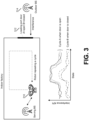
- the problem is demonstrated in FIG. 3 where a robot 310 repeats a cycle in a factory.
- interference from outdoor base station 314 experienced by the robot 310 follows a deterministic cycle-A.
- cycle-B When the door opens more interference propagates indoors and a new deterministic cycle is introduced (cycle-B).
- a state of the physical environment may indicate a state, location, position, orientation (or other physical characteristic) of physical objects in the environment. For instance, the location of robots, orientation of robot arms etc.
- the state of the loading port door 312 may be associated with a current or future radio network performance.
- the interference from the outdoor BS 314 is greater when the loading port door 312 is open.
- the state of the physical environment may be used to predict a future state of the radio network (or future state of radio network performance, and/or may be used to try different actions (e.g., different radio network actions and/or physical environment actions) to determine which action provides the best improvement in radio network performance.
- one or more actions may be performed (or even performed and then measured to determine which action(s) provide the best performance increase), such as, e.g., increasing transmission power to the UE of robot 310, or using a more robust modulation and coding scheme for a transmission to the UE/robot 310 just before the loading port door 312 opens, or changing the loading port door to open at a different time that impacts the radio network performance less.
- a method may include receiving, from one or more sensors, sensor data samples; receiving radio network information data samples associated with a radio network; determining, based on an association of one or more received sensor data samples with one or more of the received radio network information data samples, one or more associated sensor and radio network information data samples; selecting at least some of the one or more associated sensor and radio network information data samples that are relevant to performance of the radio network; and forwarding the selected associated sensor and radio network information data samples for subsequent use.
- the sensor data samples comprise spatiotemporal sensor data samples associated with a physical environment.
- spatiotemporal data samples may include data samples, which indicate a state of an object or a state of the physical environment at a particular time or sample time.
- the forwarding may include, e.g., storing the selected associated sensor and radio network information data samples, and/or forwarding the selected associated sensor and radio network information data samples for processing.
- the method may further include performing, based on the selected associated sensor and radio network information data samples, at least one action, e.g., where the action may include, for example, performing a radio network action such as adjusting a radio network parameter or configuration, and/or performing an action with respect to the physical environment such as moving or changing a state of an object) to improve performance of the radio network.
- the performing the action may include one or more of the following: one or more radio network actions; one or more automated radio network actions; one or more automated radio network actions triggered by a network self-optimization algorithm; and/or one or more non-radio network actions (e.g., actions associated with the physical environment) where an object or an aspect of the physical environment is changed to improve performance of the radio network.
- one or more radio network actions e.g., one or more automated radio network actions
- one or more automated radio network actions triggered by a network self-optimization algorithm e.g., actions associated with the physical environment
- the receiving, from one or more sensors, sensor data samples may include receiving sensor data samples associated with one or more of the following: a button, switch, or controller that controls an object or portion of the physical environment; a button, switch, or controller that controls a position, orientation or a movement of an object; a button, switch, or controller that controls a status or state of an object; a camera that captures images or video feed of an object or portion of a physical environment; and a sensor that detects a status or state of an object or portion of the physical environment.
- the receiving sensor data associated with a sensor that detects a status or state of an object or portion of the physical environment may include, e.g., receiving sensor data from a Radar or LiDAR that performs detection, ranging, bearing or location determination of an object or portion of the physical environment.
- the receiving radio network information associated with a radio network may include receiving at least one of the following, by way of illustrative example: a radio network key performance indicator for the radio network; information associated with a radio network action; and a radio network configuration parameter.
- the radio network key performance indicator may include one or more of (these are merely illustrative examples): a received signals strength; a total received power; a received interference power; and a signal to interference plus noise ratio (SINR); a pathloss; a reference signal received power; a reference signal received quality; a received signal strength indicator; a reliability; a block error rate; a latency; a jitter; a coverage; a capacity; a data transfer rate; a rank indicator; a modulation and coding scheme indicator; a channel state information; and a timing advance.
- SINR signal to interference plus noise ratio
- the determining one or more associated sensor and radio network information data samples may include, by way of example: determining, based on a time of one or more sensor data samples being within a time window of one or more of the radio network information data samples, one or more associated sensor and radio network information data samples. Also, the determining one or more associated sensor and radio network information data samples may include: determining that a first sensor is paired or associated with at least a first communications element; and, determining, based on a time of one or more sensor data samples from the first sensor that are within a time window of one or more of the radio network information data samples associated with at least the first communications element, one or more associated sensor and radio network information data samples.
- the communications element may include, e.g., a computer or a server, or a radio network element associated with the radio network, including at least one of a base station (BS), a user device (or UE), a core network element, or other radio network element.
- BS base station
- UE user device
- core network element or other radio network element.
- the selecting at least some of the one or more associated sensor and radio network information data samples that are relevant to performance of the radio network may include one or more of the following, for example: selecting at least some of the one or more associated sensor and radio network information data sample that occur or are sampled before a change in performance of the radio network; selecting at least some of the one or more associated sensor and radio network information data sample that occur or are sampled during a change in performance of the radio network; and selecting at least some of the one or more associated sensor and radio network information data sample that occur or are sampled after a change in performance of the radio network.
- the selecting at least some of the one or more associated sensor and radio network information data samples that are relevant to performance of the radio network may include one or more of: selecting at least some of the one or more associated sensor and radio network information data sample that occur or are sampled before a decrease in performance of the radio network; selecting at least some of the one or more associated sensor and radio network information data sample that occur or are sampled during a decrease in performance of the radio network; and selecting at least some of the one or more associated sensor and radio network information data sample that occur or are sampled after a decrease in performance of the radio network.
- the method may further include labeling a reason for selection of the selected associated sensor and radio network information data samples that are relevant to performance of the radio network.
- FIG. 4 is a diagram illustrating operation of a network according to an example embodiment.
- the network in FIG. 4 may include one or more sensors 410 that may generate sensor data samples associated with a state of the physical environment, e.g., such as a location, position, orientation or other state of an object.
- the network may also include a radio network 412, such may include, e.g., a core network, one or more BSs, and/or one or more UEs.
- Radio network 412 may provide radio network information data samples that indicate a state of the radio network and/or a state of radio network performance, such as indicating a value for one or more key performance indicators for the radio network, for example.
- the system may include or perform the following:
- FIG. 5 is a diagram illustration associating sensor data samples with radio network information data samples according to an example embodiment.
- Sensors 10 may sense or measure or identify one or more parameters associated with a physical environment.
- a DFA Data Filtering and Association
- ASRI Sensor and Radio-Network Information
- the storage where ASRI data 522 samples are stored is called Data Management (DM).
- a sensor data feed (SDF) 516 is output from sensors 410 to DFA 520.
- radio network (RN) 412 may include BSs, UEs, and/or core network entities, or other radio network nodes or entities.
- Radio network information (RI) 518 is output from RN 412 to DFA 520.
- FIG. 5 is a diagram illustrating an example embodiment of the DFA and DM.
- Sensors 410, and a radio network (RN) 412, a DFA 520, and a data management (DM) entity 524 are shown in FIG. 5 .
- DFA 520 (or DFA-Algorithm 520) controls the data stream towards the Data Management (DM) 524.
- SDF Sensor Data Feed
- RI Radio-Network Information
- the DFA 520 may associate and filter the relevant data from the streams (SDF 516 and RI 518) of data that are considered to be relevant for the network performance, and also labels the data with the reason of relevancy.
- There can be one or more instances of the DFA 520 meaning that different data sources may be processed by different instance of DFA 520 (DFA-Algorithm) in different physical or logical locations.
- the DFA instances can be located e.g., in RN base stations, a Mobile Edge Computing (MEC) server or any other server or computer.
- MEC Mobile Edge Computing
- the implementation of the DFA 520 (DFA-Algorithm) is implementation specific. It contains pre- programmed rules to trigger the data association.
- MEC Mobile Edge Computing
- 5G era Mobile Edge Computing
- MEC Mobile Edge Computing
- Data Management (DM) 524 is a logical entity where the associated data (ASRI) 522 may be sent to.
- the DM 524 may have one or more of the following functionalities, by way of example: data storage, instant forwarding of the incoming data, forwarding of the stored data (e.g., ASRI data).
- ASRI data stored data
- This entity is optional in a sense that the ASRI data 522 can be forwarded directly to any entity that can understand the protocol which is used to transmit the ASRI data 522.
- the architecture can be distributed or central, meaning that the data (e.g., ASRI data) streams from DFA (DFA-Algorithm) 520 instances can be connected to one or more instances of DMs 524 in different physical or logical locations.
- data e.g., ASRI data
- DFA-Algorithm DFA-Algorithm
- DFA (Data-Filtering-and-Association) 520 associates the data from the radio network and sensors, and filters and labels the relevant data from the stream of data that are considered to be relevant for the network performance.
- DFA 520 can be several instances of the DFA 520 in different logical or physical locations, meaning for instance that some sensors are connected to DFA instance inside RN base stations while rest of the sensors are connected to different DFA-Instances inside a MEC server. To allow this type of implementation, several interface protocols needs to be defined. This should also allow implementation in a multi- vendor network.
- FIG. 6 is a diagram illustrating a Data-Filtering-and-Association (DFA) according to an example embodiment.
- SDF (sensor data feed)-Interface 612 defines a protocol to transfer sensor data. The protocol may e.g., indicate the type of data, time stamp of each data sample, etc.
- RI-Interface 614 defines a protocol to transfer of radio network information (RI). The protocol may, for example, indicate the type of data, time stamp for each data sample, etc.
- DS-Interface 616 defines a protocol to transfer ASRI information to the DM 524.
- Configuration-Interface 618 defines a protocol to configure the operation or algorithm of DFA 520, e.g., based on DFA algorithm configuration data.
- Control-Interface 620 defines a protocol to send instructions from a set of pre-defined instructions to control or provide feedback to sensors 410 and/or 412. For instance, instead of continuously transmitting the SDF, when RI indicates an error in the network (e.g., which, in some cases, may be a decreased radio network performance), the interface 620 may be used to instruct a sensor to transmit the SDF of previous 10 seconds and the next 10 seconds. This saves transmission bandwidth since the sensors stream the data only when needed. In addition, the interface 620 may be used to control the data stream from the radio network.
- DFA (or DFA Algorithm) 520 may include three example functions or components, which may include: 1) Associate function 622 may perform association of the SDF and RI data.
- DFA 520 e.g., associate 622
- DFA 520 may associate data samples (associate sensor data samples and radio network information data samples) that arrive within a certain time window.
- data association may be performed by DFA 520 based on a time relationship of sensor data samples and RI samples, e.g., that arrive or have a time stamp within a time threshold.
- Such implementation is sufficient as long as it can be guaranteed that delivery of the data does not have excessive delays.
- To achieve more precise synchronization e.g.
- DFA 520 may store ASRI data samples.
- DFA memory 624 may include a memory to store N latest ASRI samples. The history of samples may be used by DFA 520 to obtain information prior the event that triggered the data association.
- Rules & program 626 of DFA 520 may include a set of rules, or a program, to trigger the association inside the own DFA instance 520, or to trigger association in another DFA instance through the control interface 620.
- Rules and program 626 may also specify which ASRI samples are stored to the memory and which samples are sent to the DM 524.
- the rules can be configured or a separate program downloaded through the configuration interface 618.
- the rules may include separate rules for different destinations receiving the associated data, for instance; one destination receives filtered data specified by one rule while other destination receives the raw data without filtering. Obviously, this can be achieved with separate DFA instances as well.
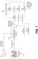
- FIG. 7 is a diagram of a data management entity according to an example embodiment.
- the role of DM may include, for example: Receive the ASRI, store the ASRI, and/or forward the received ASRI. Fetch and send the ASRI from the memory to a given destination on demand.
- DM-Interface(s) 716 defines an interface protocol to transfer ASRI-data to and/or from DM 524.
- Data Storage 712 is a logical entity that stores the ASRI, e.g., within a database.
- Program part 714 is specified by the configuration interface and it determines which ASRI samples are stored and which ASRI samples are forwarded (e.g.
- Data from source A may be configured to be stored while the data from source B is forwarded to a predefined destination, with or without storing the data first).
- Data forwarding 718 may determine which data samples are forwarded.
- Configuration Interface 720 defines a protocol to configure the DM 524. The configuration may include, e.g., data forwarding rules for specific sources.
- Control Interface 722 defines a protocol to fetch data or information from the storage.
- FIG. 8 is a diagram illustrating a robot 810 with a user equipment (UE), and a dynamic or moving blocking object 812 that impacts radio network performance for the UE.
- FIG. 9 is a diagram illustrating radio network information (RI) for a time period that is before an error, during an error, and after an error.
- RI radio network information
- a dynamic object 812 in a factory randomly blocks the signal between robot-UE 810 and BTS1 412.
- SINR drops below a threshold, which may be considered an error ( FIG. 9 ).
- DFA instance 520 is configured to monitor the error event (e.g., monitor SINR, including when SINR drops below threshold 914, FIG. 9 ) caused by the blockage.
- Sensor data feed 516 is video images provided by a camera attached to the BTS1.
- RI radio network information
- SINR radio network information
- the data association is triggered between the video images (SDF) and SINR (RI).
- the data (ASRI) before the error/event (920) is fetched from the DFA memory and is forwarded with the data (ASRI samples) during (922) the error and the data (ASRI samples) (924) after the error event.
- the samples are labelled to indicate which event triggered the association, and the state of the error (pre-error - error - post-error).
- the data association is ended according to a preconfigured rule being in this case some time interval after the error has ended.
- This data is forwarded for the DM 524 that is visualized in FIG. 9 as bursts of data from the three detected errors.
- data samples are shown for time periods before the error (920), during the error (922) and after the error (924).
- the ASRI associated SINR data and video frames
- the ASRI associated SINR data and video frames
- pre-error ASRI ASRI during error
- ASRI post-error ASRI post-error.
- the term error in this example indicates that a signal (e.g., SINR) has crossed a specific threshold, e.g., SINR has dropped below threshold 914.
- FIG. 11 is a diagram illustrating data that is forwarded or received for pre-error, error and post-error times, associated with different video frames.
- an error event occurs when the SINR drops below the threshold 914. As noted, this may occur when the dynamic blocking object 812 is within a specific range of locations or positions.
- FIG. 10 illustrates video frames of video of the dynamic blocking object 812 within pre-error locations 1010 (e.g., video frames of object 812 prior to the error condition); during the error 1012 (e.g., video frames of object 812 when the SINR of UE is below threshold 914, or during error condition); and after the error condition 1014 (video frames of object 812 after the error condition).
- video frames at 1010 shown that before the error the dynamic object 812 is approaching video frames at 1012 show that during the error the dynamic object 812 is in front of the UE; and video frames at 1014 show that after the error the object 812 is moving further away.
- the error events caused by the blockage show similar behavior with the SINR and video frames.
- FIG. 11 showing the typical video frames before-during-after the error and the SINR curves aligned based on the video images. This figure demonstrates that storing this type of data stores information that may be related to the root cause of the error caused by the signal blockage.
- the options may be described by the physical or logical locations of the sensors, DFA-Algorithm instances and DM instances. Each of the mentioned can be integral and/or external part of the RN. This means that the number of deployment options is very large and therefore only a few example deployments are demonstrated here, by way of illustrative example.
- FIG. 12 is a diagram illustrating a deployment option where the DFA-Algorithm 520 is inside a Multi-Access Edge Cloud (MEC) server.
- MEC Multi-Access Edge Cloud
- FIG. 13 is a diagram illustrating a similar deployment as with FIG. 12 , with the difference that the sensor data is aggregated to a SDF Aggregation Function 1310 which forwards the SDFs when requested by the DFA-Instance 520.
- This approach demonstrates at least two benefits compared to the example, of FIG. 12 : Sensors do not have to implement the SDF interface, and the SDF aggregation function 1310 can forward the SDFs over the SDF-Interface 1312.
- the control interface 1314 can be used to reduce the amount of data from SDFs to save transmission bandwidth. This can be done by sending a control message by the DFA-Algorithm 520 when the data is needed for association.
- FIG. 14 is a diagram shows deployment option where the sensors and DFA-Algorithm instances 520 are inside the radio network (RN) 412. Sensor data feed 516 and RI data samples 518 are shown.
- cameras example sensors
- each base station may have DFA-Algorithm instance 520 which forwards ASRI data 522 to the DM 524 outside RN.
- Advantages of this approach may include the possibility of tight synchronization in the association of sensor data and radio network information, and access to sensitive information inside the base station or RN.
- an artificial intelligence (AI) neural network may be used to improve performance of the radio network.
- AI neural network e.g., which may be referred to as an AI neural network mode, a neural network, a neural network model or a model
- Neural networks are computational models used in machine learning made up of nodes organized in layers. The nodes are also referred to as artificial neurons, or just neurons, and perform a function on provided input to produce some output value.
- a neural network requires a training period to learn the parameters, i.e., weights, used to map the input to a desired output. The mapping occurs via the function. Thus, the weights are weights for the mapping function of the neural network.
- Each neural network model may be trained for a specific task. According to an example embodiment, one task may include improving the performance of a radio network (or at least decreasing a reduction in radio network performance). The task performed by the neural network model is determined by the inputs provided, the mapping function, and the desired output.
- the neural network To provide the output given the input, the neural network must be trained, which may involve learning the proper value for a large number of parameters for the mapping function.
- the parameters are also commonly referred to as weights as they are used to weight terms in the mapping function.
- This training is an iterative process, with the values of the weights being tweaked over thousands of rounds of training until arriving at the optimal, or most accurate, values.
- the parameters are initialized, often with random values, and a training optimizer iteratively updates the parameters, also referred to as weights, of the network to minimize error in the mapping function. In other words, during each round, or step, of iterative training the network updates the values of the parameters so that the values of the parameters eventually converge on the optimal values.
- Training can either be supervised or unsupervised.
- supervised training training examples are provided to the neural network.
- a training example includes the inputs and a desired output. Training examples are also referred to as labeled data because the input is labeled with the desired output.
- the network learns the values for the weights used in the mapping function that most often result in the desired output when given the inputs.
- unsupervised training the network learns to identify a structure or pattern in the provided input. In other words, the network identifies implicit relationships in the data.
- Unsupervised training is used in deep neural networks as well as other neural networks and typically requires a large set of unlabeled data and a longer training period. Once the training period completes, the neural network can be used to perform the task it was trained for.
- learning may be performed by the neural network model based on data, and a cost function, or a reward function.
- a cost function may provide a measure or indication of how far away a particular solution is from an optimal (or desired) solution to a problem to be solved.
- a reward or reward function may indicate that an output is closer to a desired or optimal solution.
- a cost function may indicate how far away a radio network performance (e.g., resulting from a set of associated sensor and radio network information data samples) is from a desired or optimal solution.
- a desired or optimal solution in the example of improving radio network performance may be indicated as a solution that may improve (e.g., maximizes) one or more radio network key performance indicators (e.g., improves or maximizes SINR, error rate, received signal strength, of signals received by the UE ).
- a reward or reward function may be used to indicate, for example, an output that has increased or decreased radio network performance (e.g., +1 may be used to increase that a set of input data resulted in an increase in radio network performance, and a -1 may be used to indicate that a set of data resulted in a decrease in radio network performance, in order to train the model).
- the learning or training of a neural network model may be classified into two broad categories (supervised and unsupervised), depending on whether there is a learning "signal" or "feedback” available to a model.
- supervised within the field of machine learning, there may be two main types of learning or training of a neural network model: supervised, and unsupervised.
- the main difference between the two types is that supervised learning is done using known or prior knowledge of what the output values for our samples should be. Therefore, the goal of supervised learning is to learn a function that, given a sample of data and desired outputs, best approximates the relationship between input and output observable in the data.
- Unsupervised learning does not have labeled outputs, so its goal is to infer the natural structure present within a set of data points.
- Supervised learning The computer is presented with example inputs and their desired outputs, and the goal may be to learn a general rule that maps inputs to outputs.
- Supervised learning may, for example, be performed in the context of classification, where a computer or learning algorithm attempts to map input to output labels, or regression, where the computer or algorithm may map input(s) to a continuous output(s).
- Common algorithms in supervised learning may include, e.g., logistic regression, naive bayes, support vector machines, artificial neural networks, and random forests. In both regression and classification, a goal may include to find specific relationships or structure in the input data that allow us to effectively produce correct output data.
- the input signal can be only partially available, or restricted to special feedback:
- Semi-supervised learning the computer is given only an incomplete training signal: a training set with some (often many) of the target outputs missing.
- Active learning the computer can only obtain training labels for a limited set of instances (based on a budget), and also has to optimize its choice of objects to acquire labels for. When used interactively, these can be presented to the user for labeling.
- Reinforcement learning training data (in form of rewards and punishments) is given only as feedback to the program's actions in a dynamic environment, e.g., using live data.
- Unsupervised learning No labels are given to the learning algorithm, leaving it on its own to find structure in its input.
- Some example tasks within unsupervised learning may include clustering, representation learning, and density estimation. In these cases, the computer or learning algorithm is attempting to learn the inherent structure of the data without using explicitly-provided labels.
- Some common algorithms include k-means clustering, principal component analysis, and autoencoders. Since no labels are provided, there is no specific way to compare model performance in most unsupervised learning methods.
- FIG. 15 is a diagram illustrating a system that uses an artificial intelligence algorithm to train a neural network model, and then use the neural network model to improve the operation of a radio network, according to an example embodiment. Many of the blocks shown in FIG. 15 are similar to FIG. 5 , and other FIGs here.
- sensors 10 may sense or measure or identify one or more parameters associated with a physical environment.
- a DFA (Data Filtering and Association) (or DFA algorithm) 520 is the logical entity that associates the RI (radio network information) 518 and SDFs (sensor data feeds) 516. The associated data is called Associated Sensor and Radio-Network Information (ASRI) 522.
- DFA Data Filtering and Association
- ASRI Associated Sensor and Radio-Network Information
- the storage where ASRI data 522 samples are stored is called Data Management (DM) 524.
- a sensor data feed (SDF) 516 is output from sensors 410 to DFA 520.
- radio network (RN) 412 may include BSs, UEs, and/or core network entities, or other radio network nodes or entities.
- Radio network information (RI) 518 is output from RN 412 to DFA 520.
- the DFA 520 may associate and filter the relevant data from the streams (SDF 516 and RI 518) of data that are considered to be relevant for the network performance, and may label the data with the reason of relevancy.
- an artificial intelligence (AI) algorithm 1510 which may be running on one or more computers or servers, may receive training ASRI data 1520, and may train a neural network model 1512.
- AI artificial intelligence
- Various types of training or learning may be used to train the model 1512, e.g., such as supervised learning, unsupervised learning, and reinforcement learning, as examples.
- a first set of ASRI data e.g., training data 1520
- AI algorithm 1510 may be used by AI algorithm 1510 to train model 1512.
- a second set of data (e.g., live data or live ASRI) 1522 may be used by AI algorithm, based on the trained model 1512, to perform (or cause another entity to perform) one or more actions that may improve the performance of radio network 412.
- a two-part (or multi-step) process may be employed that may include, e.g.,: 1) a training process in which AI algorithm 1510 trains the neural network model 1512; and 2) a radio network (RN) optimization process, e.g., in which further ASRI data (e.g., live ASRI data 1522) may be received by AI algorithm 1510 and used to perform (or trigger or cause another entity to perform) one or more actions to improve the performance of radio network 412.
- RN radio network
- the actions performed may include radio network actions and non-radio network actions.
- the actions may be predictive actions or preemptive actions, e.g., which may preemptively attempt to improve a radio network performance, based on the trained model and the live ASRI data.
- preemptive actions may include one or more radio network actions and/or one or more non-radio network actions that may be designed (or estimated) to improve radio network performance or at least reduce a decrease in performance (e.g., an expected or predicted decrease in RN performance) of the radio network based on the trained model 1512 and the live data or live ASRI data 1522.
- Performing an action or causing another entity to perform an action may include, e.g., one or more of: performing or causing another entity to perform one or more radio network actions; providing one or more input parameters to a network optimization entity or another entity; performing or causing another entity to perform one or more non-radio network actions where an object or an aspect of a physical environment is changed.
- Performing or causing another entity to perform one or more non-radio network actions where an object or an aspect of a physical environment is changed may include performing or causing another entity to perform a change in a position, location, orientation, speed and/or movement of an object (e.g., robot, wall, or any other object or portion of a physical environment) that impacts performance of the radio network.
- an object e.g., robot, wall, or any other object or portion of a physical environment
- performing (or causing another entity to perform) a radio network action may include, e.g., performing (or causing another entity to perform) a radio network action related to at least one of the following: a handover of a user device to a target base station; a load balancing of traffic or data between two or more base stations; a link adaptation for a radio link between a base station and a user device; a cell selection or cell reselection performed by a user device; a scheduling; a resource allocation; a transmit power control; and a timing advance adjustment.
- the system may also perform the following: determining a resulting change in a performance of the radio network in response to the one or more radio network actions and/or one or more non-radio network actions; determining a reward associated with the performed one or more radio network actions and/or performed one or more non-radio network actions, wherein the reward is based on whether the performed one or more radio network actions and/or performed one or more non-radio network actions results in or is associated with an increase or decrease in performance of the radio network.
- the improving performance of the radio network may include outputting at least one of the following: a key performance indicator (KPI) of the radio network for a next data sample; and an estimated best action and/or probability distribution over available actions or an estimated reward for each of one or more actions, using one or more of Q-Learning, policy gradient, or actor-critic algorithms.
- KPI key performance indicator
- the neural network model may estimate a state transition function between inputs (e.g., ASRI data) that include a plurality of associated sensor and radio network information data samples before time t and outputs that include one or more predicted sensor data samples and/or one or more predicted radio network information data samples after time t.
- inputs e.g., ASRI data
- ASRI data e.g., ASRI data
- the system may perform the following after training of the neural network model: determining a predicted future state of the radio network based on the second set of one or more associated sensor and radio network information data samples and the model: determining that the predicted future state of the radio network indicates that a predicted performance of the radio network is expected to be below a threshold; and, performing at least one of the following to improve performance of the radio network: 1) providing information, including the predicted future state of the radio network to a network optimization entity; 2) performing or causing another entity to perform a non-radio network action; and 3) performing or causing another entity to perform a radio network action.
- the receiving, from one or more sensors, sensor data samples may include receiving sensor data samples associated with one or more of the following: 1) a button, switch, or controller that controls an object or portion of the physical environment; 2) a button, switch, or controller that controls a position, location, orientation or a movement of an object; 3) a button, switch, or controller that controls a status or state of an object; 4) a camera that captures images or video feed of an object or portion of a physical environment; and 5) a sensor that detects a status or state of an object or portion of the physical environment.
- the receiving radio network information data samples associated with a radio network may include receiving at least one of the following: 1) a radio network key performance indicator for the radio network; 2) information associated with a radio network action; and 3) a radio network configuration parameter.
- a radio network key performance indicator may include (by way of illustrative examples) one or more of: a received signals strength; a total received power; a received interference power; and a signal to interference plus noise ratio (SINR); a pathloss; a reference signal received power; a reference signal received quality; a received signal strength indicator; a reliability; a block error rate; a latency; a jitter; a coverage; a capacity; a data transfer rate; a rank indicator; a modulation and coding scheme indicator; a channel state information; and a timing advance.
- SINR signal to interference plus noise ratio
- AI algorithm 1510 may be used to train a neural network model 1512 (e.g., based on a first set of ASRI data or training data), and then the AI algorithm 1510, based on the trained model 1512, may determine actions to be performed and/or output control information 1524 to perform (or cause another entity to perform) one or more actions to improve performance of the radio network.
- a neural network model 1512 e.g., based on a first set of ASRI data or training data
- the radio network may perform predictive (or preemptive) self-optimization by artificial intelligence algorithm 1510 that may use radio network KPIs & parameters and data from sensors that sense spatiotemporal changes from the environment (e.g., ASRI data), to learn correlating patterns among them (e.g., patterns of behavior that are typically correlated, between the sensor data and the associated radio network information).
- AI algorithm 1510 may use radio network KPIs & parameters and data from sensors that sense spatiotemporal changes from the environment (e.g., ASRI data), to learn correlating patterns among them (e.g., patterns of behavior that are typically correlated, between the sensor data and the associated radio network information).
- radio network performance is improved by performing an action from a set of actions which is considered to (e.g., most likely to) improve the radio network performance the most given the recent data from sensors and radio network (e.g., based on the trained neural network model 1512).
- the AI algorithm 1510 and associated neural network model 1512 may be trained with recordings (stored data) of sensor data and radio network information data that have led to events relevant for the radio network performance. Alternatively, the AI algorithm 1510 may be trained directly with the live data feed 1522. Based on a high-quality training data (high quality ASRI data), the AI algorithm 1510 may build (e.g., within neural network model 1512) an understanding on how the data streams (sensor data and radio network information) look before certain events in the network. For instance, with camera as a sensor, the neural network 1512 may learn after a few occurrences that radio link failure follows when UE moves behind a blocking object.
- the AI algorithm 1510 may be able to trigger (e.g., cause) an action such as a handover of the UE/user device when the camera feed (sensor data feed) indicates that the UE is going to move behind the blocking object, e.g., based on its current path and speed, as indicated over multiple data samples or video frames, for example.
- the system may perform several operations: 1) Sensors capturing spatiotemporal data from the environment; 2) Radio-Network (RN) capturing RN Information (RI); 3) RI is associated with the sensor data feed (SDF) (Associated Sensor & Radio-Network Information ASRI); 4)
- SDF Sensor & Radio-Network Information ASRI
- the ASRI samples considered to be relevant for network performance are labeled and selected from the stream of ASRI data; 5) The relevant associated data samples are stored to a database or forwarded directly for further processing.
- a training process is performed, e.g., where Artificial Intelligence (AI) based model learns correlating patterns among SDF & RI from historical data known to lead to events relevant for network performance (an example of correlating patterns among sensor data and RI may include: Forklift moves from position X to position y, this typically leads to decrease in SINR for RI for a UE); and, 7) RN optimization (or radio network performance improvement), where the AI based algorithm 1510 may provide input or control information to perform actions (e.g., preemptive actions or predictive actions, which may include radio network actions and/or non-radio network actions) to improve (e.g., optimize) radio network performance.
- actions e.g., preemptive actions or predictive actions, which may include radio network actions and/or non-radio network actions
- the neural network model 1512 may learn correlating patterns between SDF and RI for events that are relevant to the performance of the radio network 412. This may include the AI algorithm 1510 training the neural network model (e.g., without necessarily performing any resulting actions). Different AI learning techniques may be used to train the neural network model 1512. In addition, after training (and/or during training) of the neural network model 1512, live ASRI data may be received by AI Algorithm 1510 and fed to neural network model 1512. Based on the live ASRI data, the trained neural network model 1512 may output an indication of one or more actions to be performed, e.g., to improve the performance of the radio network 412.
- actions to be performed may include radio network actions and/or non-radio network actions.
- some data e.g., live data or a second set of ASRI data
- a control loop may be used to measure a resulting change in radio network performance that resulted from (or associated with) the applied action.
- the ASRI data may be fed to the AI algorithm and neural network model 1512 to detect error(s) (such as a resulting subsequent radio network performance that does not improve, or does not improve as much as expected based on the applied action), and then the neural network model 1512 may be updated based on this resulting radio network performance feedback to reduce error.
- error(s) such as a resulting subsequent radio network performance that does not improve, or does not improve as much as expected based on the applied action
- the neural network model 1512 may be updated based on this resulting radio network performance feedback to reduce error.
- AI methods such as supervised, un-supervised or reinforcement learning methods may be used to train the neural network model based on ASRI data.
- the training can be performed with live data and/or with data from a database.
- the neural network model describes input-output relationship of information found from ASRI data. The model depends on the use case and implementation.
- Some, but not limiting, examples may include: 1) Train a neural network model 1512 to approximate the state transition function where the inputs are n latest ASRI samples before time t and output are m ASRI samples after time t. Therefore, the trained neural network model 1512 may, at least partially, predict or forecast the upcoming samples when given the recent samples as input. This information may be used later to perform the actions. Furthermore, based on subsequent ASRI feedback, the neural network model may evaluate a goodness (or success) of the performed actions, e.g., by approximating input-output relationship (with neural network) between the n latest ASRI samples and consequences of an action evaluated by a reward function (e.g., in a simple case, a reward is +1 if radio network performance improved and -1 otherwise).
- neural network model 1512 After the neural network model 1512 has been trained, then use neural network model to trigger the actions (predictive or preemptive actions), when certain ASRI data is received (e.g., certain ASRI data is received that may match a particular pattern known by the neural network model 1512).
- certain ASRI data e.g., certain ASRI data is received that may match a particular pattern known by the neural network model 1512.
- the model After the model is trained, there are several alternatives how to implement the algorithm that performs the optimization actions, for instance: Provide forecast information of network conditions for a pre-programmed optimization algorithm. This way the model could e.g. give a warning signal of certain error events before they take place.
- the trained neural network model may be used as a starting point for reinforcement learning algorithm which executes the actions and learns over time the optimal actions that may be preferred in order to optimize or improve radio network performance under different conditions (as indicated by different ASRI data).
- the method may perform (or cause or trigger) actions after certain amount of training data is obtained from the live network after which the reinforcement learning may begin.
- the neural network model 1512 may predict a future radio network KPI (e.g., predict SINR for UE at next data sample). This information may be used to perform or cause another entity to perform an action to improve radio network performance (e.g., increase SINR, or reduce an amount of decrease in SINR in a future ASRI sample). The predicted SINR may be provided to another entity, which may then perform an action.
- Base station sleep modes e.g., coverage, capacity, energy and reliability
- link adaptation e.g., MIMO rank adaptation
- link management multi-connectivity, add or remove links, such as adding a link to improve connection robustness
- URLLC reliability & latency management e.g., handover decisions (e.g., cause UE to perform a handover from BS1 to BS2 that is not blocked or interfered with); Beamforming / beam management (e.g., switch UE to a different beam to avoid an interfering object); Power control (e.g., cause UE to increase transmission power); Interference coordination (e.g., send a message to adjacent BS to control interference from that BS); Antenna tilt or location optimization; quality-of-service/quality-of-experience management (these include items already listed).
- Base station sleep modes e.g., link adaptation; MIMO rank adaptation
- link management multi-connectivity, add or remove links, such as adding a link to improve connection robustness
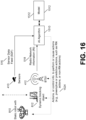
- FIG. 16 is a diagram of a system according to another example embodiment.
- the robot with a UE may be interfered with in some cases based on a moving blocking object (e.g., the moving forklift).
- the neural network model may learn (or may be trained based on) one or more correlating patterns of the ASRI data. For example, over a number of ASRI data sets, the neural network model 1512 may learn that when the object (e.g., forklift) 812 moves from position x to position y, this is associated with an immediate decrease in SINR (signal to interference plus noise ratio) of the UE of the robot 810.
- SINR signal to interference plus noise ratio
- live training ASRI data may be received by the trained neural network model, and different actions may be performed (or caused to be performed by another entity) in response to detecting this correlating pattern of the object moving from position x to position y.
- the neural network model 1512 may be further trained to further improve radio network performance.
- the best (or optimum) improvement in SINR of the UE in this situation may be to increase transmission power of the UE by z dB, and decrease the modulation and coding scheme (MCS) to a lower MCS, e.g., to allow communications between the UE and BTS1 to be more robust, and avoid a decrease in SINR.
- MCS modulation and coding scheme
- a preferred action may be to perform an immediate handover of the UE from BS1 (or BTS1) to BTS2 (not shown) that is not blocked by the blocking object, e.g., to avoid (or minimize) a decrease in the UE SINR (e.g., either the SINR measured by UE and reported to BS1, or SINR measured by BS1).
- the neural network model 1512 may be trained to learn one or more correlating patterns of the ASRI data, and then subsequent data may be used by the neural network model 1512 to cause one or more actions to be performed to improve radio network performance.
- FIG. 17 is a block diagram illustrating a system in which separate DFA instances are used to filter training data and live data according to an example embodiment.
- a DFA instance 520A is used to filter or identify errors (or ASRI data not pertinent to performance of the radio network, such as ASRI data associated in time with a decrease in SINR) for the training ASRI data 522, while a DFA instance 520B is used to sample ASRI data for the live ASRI data 1522 that may be used to cause or trigger actions.
- DFA instance 520A may filter to provide DM 524 only with ASRI data associated with one or more errors or decreases in radio network performance (such as the ASRI, including SDF/video frames associated in time with the decrease in SINR of the UE).
- ASRI data may be used to train the neural network model 1512, for example.
- the DFA instance 520B may sample (but doesn't necessarily filter) ASRI data, to be provided as sampled live ASRI data 1522.
- Neural network model 1512 may then attempt to identify such correlating patterns in the ASRI data, to cause corrective actions to be performed, e.g., in attempt to improve the performance of the radio network.
- radio network information may include SINR experienced by the robot UE (810) and SDF may include video image(s) from a camera attached to the BTS1 (which may indicate location of blocking object 812). Therefore, for example, the AI algorithm 1510 and neural network model 1512 may learn the correlation between the video images and SINR to predict the upcoming error that is caused by the blockage. To do this, training data is needed from the error situation to train the model. After the training is complete, the model needs continuous stream of live data to detect the upcoming errors.
- the neural network model 1512 may be looking for changes in position of the forklift, to flag or cause corrective actions to be performed, which may be a preemptive or predictive action since corrective action (at least in some cases) may be performed before the error (e.g., a decrease in SINR, or a significant decrease in SINR that would cause a disconnection of the UE from BTS1) actually occurs, based on the live ASRI data 1522 and the trained neural network model 1512 (which is now trained to recognize the the correlation between the object 812 moving from location x to location y, and a decrease in UE SINR, for example).
- corrective actions may be a preemptive or predictive action since corrective action (at least in some cases) may be performed before the error (e.g., a decrease in SINR, or a significant decrease in SINR that would cause a disconnection of the UE from BTS1) actually occurs, based on the live ASRI data 1522 and the trained neural network model 1512 (which is now trained to recognize the the correlation between the
- the system provides a technical advantage of allow an action, such as a preemptive corrective action, to be performed that may avoid an error or decrease in radio network performance, or to perform the corrective action before the predicted or expected error actually occurs.
- an action such as a preemptive corrective action
- This is in contrast to a reactive action that may be performed after the error (e.g., drop in SINR of the UE) is actually detected, and the BTS1 may attempt a handover of the UE, but it may be too late to perform such a handover, and the connection between the BTS1 and the UE may be lost at that point when a reactive action is performed.
- the first DFA-instance 520A may collects the training data: DFA instance 520A is configured to monitor the error event (e.g., decrease in SINR) caused by the blockage.
- the error event e.g., decrease in SINR
- the data association is triggered.
- the data before the event is fetched from the memory of DFA and sent forward with the data after the error event.
- the samples are labelled to indicate which event triggered the association, and the state of the error (before-during-after).
- the data association is ended according to a preconfigured rule being in this case some time interval after the error have ended. This data is forwarded for the DM that is visualized in FIG. 17 as bursts of data from the three detected errors.
- the second DFA-instance is configured to stream live ASRI data for the AI algorithm 1510 and neural network model 1512.
- the data association is configured to be done one time after every predefined sampling interval. This data is then forwarded directly for the AI algorithm 1510 and neural network model 1512 to be consumed.
- the AI algorithm and/or neural network model identifies and performs preemptive corrective actions (e.g. (before the error occurs or before the error becomes too severe) to solve the upcoming error.
- preemptive corrective actions may include, e.g., increasing transmission power, adjusting the MCS, performing a handover, or any other radio network change or adjustment, or a non-radio network action.
- the neural network model 1512 may be trained with the ASRI data from the 1st DFA instance 520A and the preemptive corrective actions are performed based on the sampled live ASRI data from the 2nd DFA instance 520B.
- FIG. 9 demonstrates why the described way of collecting the training data helps to build a predictive AI model.
- FIG. 9 shows three blockage-error events where the SINR drops below the threshold.
- FIG. 9 indicates the areas before-during-after the error.
- FIG. 10 shows the video frames during the first error showing that: before the error the dynamic object is approaching (1010); during the error the dynamic object is front of the UE (1012); and after the error the object is moving further away (1014).
- FIG. 11 shows the typical video frames before-during-after the error and the SINR curves of three different errors events aligned based on the video images.
- FIG. 11 demonstrates that storing this type of data stores information of the root cause of the error caused by the blockage. Therefore, when training the AI model with this data the model may be able to identify the ASRI samples that are leading to errors.
- FIG. 18 illustrates SINR data samples from live data that is input to the neural network model 1512 according to an example embodiment.
- the four ASRI samples (1810, 1820, 1830, 1840, e.g., indicating change in position of object over four video frames) shown in FIG. 18 indicate (in this example, based on known correlating patterns known by model 1512) that the dynamic object is going to block the radio signal and cause a significant decrease in SINR (for example). If the neural network model 1512 is properly trained, and when giving the neural network model 1512 these live ASRI samples, the neural network model 1512 can predict the error (e.g., signal blockage or significant decrease in SINR for the UE), and thus preemptive corrective actions can be performed to solve or address the issue (e.g., preemptive corrective action(s) may be performed to avoid the error and/or to at least decrease severity of the error).
- the error e.g., signal blockage or significant decrease in SINR for the UE
- FIG. 19 is a diagram illustrating operation of reinforcement learning according to an example embodiment.
- Reinforcement learning is a subfield of machine learning, where the machine learning algorithm learns to perform a given task by trial and error.
- the agent e.g., software agent
- the agent refers to or may include the entity (e.g., AI algorithm 1510 and/or neural network 1512) that may be trained, and then adjusted or adapted based on various actions that are performed.
- the environment may refer to various parameters or objects that may be measured (e.g., ASRI data), and/or controlled via applied actions.
- the basic principle of reinforcement learning is illustrated in FIG. 19 , where the environment is in state-s and receives a reward-r after taking some action-a.
- the reinforcement algorithm When taking a new action, the environment is in a new state and receives a new reward.
- the reinforcement algorithm tries to learn which action to take in which states to maximize the future reward.
- the reinforcement learning may work as follows: State of the environment could be described as locations of the objects parameters of the radio network, and/or sensor data such as video camera images (ASRI data); Actions may include radio network actions and/or non-radio network actions, such as adjusting MCS or transmission power, performing a handover, moving the base station antennas, or other action.
- the Reward may be detected as or based on an improved UE SINR compared to previous state, or improved UE reliability.
- FIG. 20 is a block diagram illustrating a neural network architecture (neural network model) according to an example embodiment.
- the Neural network architecture of FIG. 20 provides a function between multiple inputs (X), and multiple outputs (Y); Arrows indicate the flow of data from the bottom to the top in FIG. 20 .
- inputs (X) are received at time t from sensors.
- a well known neural network method is performed, including Convolution long short term memory (ConvLSTM) that uses prior knowledge and convolution, based on inputs (e.g., video data frames) and considers previous video frames (e.g., to see forklift moving). Also, the number of parameters can be reduced by using convolution.
- Convolution long short term memory Convolution long short term memory
- residual block 1b (there may be multiple residual blocks) provides further (or deep) learning, e.g., evaluating the data at lower and lower resolutions.
- the neural network will correct or adjust the number of nodes or vectors to the correct size, to provide a probability value for each action, For example, if there are 100 actions, then the neural network may provide 100 outputs.
- the neural network outputs Q values, based on a reinforcement learning referred to as Q learning, which is a function that takes in sensor values (input X), and output is probability distribution of actions, e.g., what is a best action based on these inputs.
- Q learning a reinforcement learning referred to as Q learning
- output is probability distribution of actions, e.g., what is a best action based on these inputs.
- Similar network architecture could be used in A3C algorithm where the output Y would consist of policy P(X) and value estimate V(X), where X is the state or input.
- Y Y
- Q learning is an algorithm that may select a best action, or largest output value, and then apply that corresponding action on Radio network, and measures if that rewards was achieved, and updates probability or Q values of that action.
- A3C algorithm the network would already select the policy (probability of each action) and value estimation for each of the actions.
- FIG. 21 is a block diagram illustrating a neural network architecture (neural network model) that uses multiple input modalities according to an example embodiment.
- Different modes or modalities of input data may be input or provided, e.g., such as video frames, radar data, and LiDAR data.
- each of these types of data may be separately processed, and then a deep learning is performed based on all of the input modalities.
- a modality specific-Convolution long short term memory (ConvLSTM) is performed for video (2110), radar (2120) and LiDAR (2130).
- ConvLSTM modality specific-Convolution long short term memory
- ConvLSTM modality specific-Convolution long short term memory
- the neural network outputs Q values estimation for each action for multi-model inputs.
- the network would output V(X) and P(X) instead of Q(X).
- the beginning of the network may be split so that there are some layers that are modality dependent (for different modalities or input types, such as video, radar, LiDAR, in this example), and those layers are then connected or combined to modality agnostic part of the network as depicted in FIG. 21 .
- a neural network model that includes multiple input modalities, this can improve the results and also enables better pretraining of the neural network, since data of different types or modalities may be used for training.
- FIG. 22 is a block diagram that illustrates an overview of different learning that may be used and/or combined to train a neural network model according to an example embodiment. As shown in FIG. 22 , three options are shown for learning, including: option A) supervised training; option B) supervised plus reinforcement learning; and Option C) reinforcement learning only.
- the model (neural network model) may be pretrained with prerecorded data, to obtain a pretrained model.
- the input data e.g., ASRI data
- the model may be trained to obtain an environment model, and at 2230, the runtime phase may be performed in which the model is used based on live data to determine and/or perform actions.
- Option B is performed (supervised plus reinforcement learning)
- reinforcement learning (RL) training phase may (optional) be performed, e.g., to obtain a pretrained RL model.
- RL runtime training is performed with live data.
- reinforcement learning training phase may be performed (optional), e.g., to obtain a pretrained RL model.
- reinforcement learning (RL) runtime training with live data is performed.
- Supervised only method is trained with real data and actions recorded from the environment.
- the training objective can be, e.g., to try to learn the state of the system in the future, given previous frames and actions.
- the neural network model can predict radio network KPIs (e.g., a SINR for a next or subsequent data sample), etc.
- the output of the supervised method is the Environment model. It can be used as an input to a pre-defined adaptive system. For instance, the model could indicate the upcoming errors for a pre-programmed optimization algorithm. Simplest way is to use supervised only, as it does not have reinforcement learning.
- Output is environment model - in a simple example related to the forklift example, the environment model (a neural network) may indicate, probabilities for one or more (or all) KPIs :
- SINR Predicts SINR of a UE for next time stamp/sample; would indicate a most probable SINR value for next sample/time stamp, for each BS.
- Option B Supervised + Reinforcement Learning: Environmental model created by observing the environment.
- the neural network model may be attempting to create a policy (or model) of what actions should be performed for different inputs, based on reward system.
- SINR reduces when Forklift moves, but there are no actions applied yet.
- different actions are applied (e.g., for Q learning - each output indicates expected reward if the action is taken); so apply different actions, and observe output, and then adjust Q values, depending on reward achieved based on applied action)
- the reinforcement learning model is trained directly without any pretraining. It may contain a RL training phase, where the method is allowed to explore the different output options in a realistic situation, but where mistakes can be overcome.
- FIG. 23 is a block diagram illustrating a training phase for a neural network model based on options A and B according to an example embodiment.
- pretraining data for supervised learning
- agent e.g., AI algorithm and/or neural network model
- runtime training data for reinforcement learning
- training or pretraining may be based on modality specific parts (see e.g., FIG. 21 ) of the environment model by cross-referencing different input modalities.
- FIG. 24 is a block diagram illustrating a runtime phase for a neural network model based on option A according to an example embodiment.
- live data live ASRI data
- action-value function approximation 2314 of agent 2310 Based on the trained neural network model and the live ASRI data, action-value function approximation 2314 of agent 2310 generate output (e.g., probability values, predictive KPIs for radio network, such as SINR for next time sample or Q-values) based on St (state 2312, or live ASRI data) and a (actions performed).
- the output of the agent 2310 may be input to a pre-programmed self-optimization algorithm 2410.
- the self-optimization algorithm 2410 may determine one or more actions (e.g., preemptive corrective actions, such as radio network actions or non-radio network actions) to be performed to improve the performance of the radio network 412.
- the self-optimization algorithm 2410 may indicate (or send control information indicating) a preemptive corrective action to be performed.
- Action-Value approximation Q 2314 may be a neural network model that estimates which action(s) should be taken based on state St, which is based on current ASRI data (or subset of the ASRI data).
- live mode - output from 2310 or 2314 may include Q values for each of multiple actions.
- the outputs may be either 1) a predicted KPI for next time sample (e.g., expected SINR for next time sample); or 2) Q values - may be or may include an estimate of expected future reward for each of multiple actions (e.g., an action associated with highest reward or highest Q value may be performed).
- a predicted KPI for next time sample e.g., expected SINR for next time sample
- Q values - may be or may include an estimate of expected future reward for each of multiple actions (e.g., an action associated with highest reward or highest Q value may be performed).
- FIG. 25 is a block diagram illustrating a runtime phase for a neural network model based on option B in which a policy for determining an action is included within an agent 2510.
- the agent 2510 including the action-value function approximation neural network 2314 learns the optimal policy 2512 for selecting the actions. This will require trial and error to converge towards optimal solution.
- the policy 2512 is generated or created by the agent itself - agent 2510 selects the action.
- the neural network (action-value function approximation 2314) provides prediction of environment state - e.g., the KPI prediction for multiple KPIs (which might be expected KPI values for next time sample).
- option C the main difference to options A & B ( FIGs. 23-24 ) is that this approach doesn't have any pre-programmed capabilities to control the network.
- the algorithm starts without any prior information on how to control the network.
- the goal is to learn the optimal policy to control the network via reinforcement learning. Therefore, this approach could be most suitable for situations where errors are tolerated, such as deployment optimization phase of the network before setting the network live. This is also suitable for cases with novel sensors or novel environments that cannot be easily pretrained.
- various example embodiments may provide a predictive model, to take actions, based on the ASRI data and the model, to improve performance or radio network.
- the system (based on the trained neural network model and live ASRI data) may provide or indicate preemptive corrective actions that can be performed to avoid negative RN events or improve RN performance (the action may improve RN performance, as compared to if action had not been performed).
- Some example Advantages may include one or more of:
- the association of RI and sensor data captures additional information on events in the environment that impacts the network performance. This allows to perform predictive self-optimization (or preemptive corrective actions) that would have not been otherwise possible because in many cases traditional radio network information used for network optimization doesn't indicate the upcoming events early enough and therefore the traditional algorithms are reactive rather than preemptive (or predictive).
- An AI neural network model may be trained based on associated sensor data (e.g., based on data associated with physical environment) and radio network information (ASRI). In this manner, the AI neural network model may learn correlating patterns among the ASRI data. As an example correlating pattern, the AI neural network model, based on training ASRI data, may learn that a forklift moving from position x to y is associated with (or is correlated with) a significant decrease in UE SINR within z ms (e.g., within 2 ms).
- one or more actions may be performed, and resulting ASRI may be received by the neural network model, and the AI neural network model (e.g., weights of the neural network model) may be adjusted or adapted based on which actions improve radio network performance (e.g., which actions cause a highest resulting UE SINR for the next data sample or next n data samples), and which actions do not improve radio network performance, for various ASRI data.
- the AI neural network model e.g., weights of the neural network model
- the AI neural network model may be adjusted or adapted based on which actions improve radio network performance (e.g., which actions cause a highest resulting UE SINR for the next data sample or next n data samples), and which actions do not improve radio network performance, for various ASRI data.
- live ASRI data may be input to the trained AI neural network model to trigger one or more preemptive corrective actions (e.g., radio network actions and/or non-radio network actions) in order to improve performance of the radio network, e.g., such as one or more actions that have been shown to result in a highest UE SINR for the next data sample or next n data samples.
- preemptive corrections actions may be performed to improve radio network performance, rather than performing a reactive action that may typically be performed only after a significant degradation in radio network performance has been detected.
- an associated video stream may reveal that the reason for sudden radio link degradation is an object blocking the radio signal, or an associated press of a button may reveal that opening a door introduces significant interference within certain area of the building from outdoor base stations.
- Providing associated RI and SDF may be used to make decisions on one or more actions that may be performed to improve RN performance (or actions that may be used to prevent an error), or actions that may be triggered to improve RN performance.
- These actions that may be triggered may include a RN action (e.g., increasing transmission power, performing a handover of the UE, switching the UE to a more robust MCS, ...), or actions associated with the physical environment, e.g., such as changing the movement or timing of movement of a blocking object, changing a positioning or orientation of a blocking object, or other change in status of the physical environment.
- RN action e.g., increasing transmission power, performing a handover of the UE, switching the UE to a more robust MCS, .
- actions associated with the physical environment e.g., such as changing the movement or timing of movement of a blocking object, changing a positioning or orientation of a blocking object, or other change in status of the physical environment.
- the system may perform a RN action, such as performing a handover of the UE from BTS1 to BTS2 when blocking object reaches 140m, or increases transmission power when blocking object reaches 150m.
- the neural network model may learn these correlating events, and then may be used, when presented with similar live data, to trigger or cause preemptive corrective actions to be performed to address or reduce the problem.
- the association of RI and sensor data captures additional information on events in the environment that impacts the network performance.
- the information leading to these events are stored which can be used e.g., to train models that are able to predict these events based on live data feed.
- an associated video stream may reveal that the reason for sudden radio link degradation is an object blocking the radio signal (as illustrated in FIG. 2 ), or an associated press of a button may reveal that opening a door introduces significant interference within certain area of the building from outdoor base stations (as illustrated in FIG. 3 ).
- indoor to outdoor isolations may have significant impact on reliability level.
- opening a factory door may be equivalent to isolation reduction of 10 to 20 decibels.
- Examples and techniques are not restricted to the given examples.
- the examples and techniques may be applicable to any use case where spatiotemporal changes have impact on radio network performance e.g.: Logistics automation: sensors may track movement of containers, in logistic center or harbor, that have significant impact for the wireless connectivity; Connected hospitals: opening a door in MRI or surgery room may introduce interference (these types of rooms are typically isolated from radio waves); Elevators with wireless connectivity: sensor may track state of the elevators in an elevator shaft which is relevant for the quality of connectivity; Connected-Cars/Trains or eMBB users within cars/trains: sensor data may indicate e.g. that the car/train is approaching 5G network coverage outage area.
- FIG. 26 is a flow chart illustrating operation of a system according to an example embodiment.
- Operation 2610 includes receiving, from one or more sensors, sensor data samples.
- Operation 2620 includes receiving radio network information data samples associated with a radio network.
- Operation 2630 includes determining, based on an association of one or more received sensor data samples with one or more of the received radio network information data samples, a first set of one or more associated sensor and radio network information data samples.
- Operation 2640 includes developing a model that is trained based on at least a portion of the first set the associated sensor and radio network information data samples that are relevant to performance of the radio network.
- operation 2650 includes improving performance of the radio network based on at least the model.
- FIG. 27 is a block diagram of a wireless station (e.g., AP, BS or user device, or other network node) 2700 according to an example embodiment.
- the wireless station 2700 may include, for example, one or two RF (radio frequency) or wireless transceivers 2702A, 2702B, where each wireless transceiver includes a transmitter to transmit signals and a receiver to receive signals.
- the wireless station also includes a processor or control unit/entity (controller) 2704 to execute instructions or software and control transmission and receptions of signals, and a memory 2706 to store data and/or instructions.
- Processor 2704 may also make decisions or determinations, generate frames, packets or messages for transmission, decode received frames or messages for further processing, and other tasks or functions described herein.
- Processor 2704 which may be a baseband processor, for example, may generate messages, packets, frames or other signals for transmission via wireless transceiver 2702 (2702A or 2702B).
- Processor 2704 may control transmission of signals or messages over a wireless network, and may control the reception of signals or messages, etc., via a wireless network (e.g., after being down-converted by wireless transceiver 2702, for example).
- Processor 2704 may be programmable and capable of executing software or other instructions stored in memory or on other computer media to perform the various tasks and functions described above, such as one or more of the tasks or methods described above.
- Processor 2704 may be (or may include), for example, hardware, programmable logic, a programmable processor that executes software or firmware, and/or any combination of these.
- processor 2704 and transceiver 2702 together may be considered as a wireless transmitter/receiver system, for example.
- a controller (or processor) 2708 may execute software and instructions, and may provide overall control for the station 2700, and may provide control for other systems not shown in FIG. 27 , such as controlling input/output devices (e.g., display, keypad), and/or may execute software for one or more applications that may be provided on wireless station 2700, such as, for example, an email program, audio/video applications, a word processor, a Voice over IP application, or other application or software.
- applications may be provided on wireless station 2700, such as, for example, an email program, audio/video applications, a word processor, a Voice over IP application, or other application or software.
- a storage medium may be provided that includes stored instructions, which when executed by a controller or processor may result in the processor 2704, or other controller or processor, performing one or more of the functions or tasks described above.
- RF or wireless transceiver(s) 2702A/2702B may receive signals or data and/or transmit or send signals or data.
- Processor 2704 (and possibly transceivers 2702A/2702B) may control the RF or wireless transceiver 2702A or 2702B to receive, send, broadcast or transmit signals or data.
- 5G Another example of a suitable communications system is the 5G concept. It is assumed that network architecture in 5G will be quite similar to that of the LTE-advanced. 5G is likely to use multiple input - multiple output (MIMO) antennas, many more base stations or nodes than the LTE (a so-called small cell concept), including macro sites operating in co-operation with smaller stations and perhaps also employing a variety of radio technologies for better coverage and enhanced data rates.
- MIMO multiple input - multiple output
- NFV network functions virtualization
- a virtualized network function may comprise one or more virtual machines running computer program codes using standard or general type servers instead of customized hardware. Cloud computing or data storage may also be utilized.
- radio communications this may mean node operations may be carried out, at least partly, in a server, host or node operationally coupled to a remote radio head. It is also possible that node operations will be distributed among a plurality of servers, nodes or hosts. It should also be understood that the distribution of labour between core network operations and base station operations may differ from that of the LTE or even be non-existent.
- Embodiments of the various techniques described herein may be implemented in digital electronic circuitry, or in computer hardware, firmware, software, or in combinations of them.
- Embodiments may implemented as a computer program product, i.e., a computer program tangibly embodied in an information carrier, e.g., in a machine-readable storage device or in a propagated signal, for execution by, or to control the operation of, a data processing apparatus, e.g., a programmable processor, a computer, or multiple computers.
- Embodiments may also be provided on a computer readable medium or computer readable storage medium, which may be a non-transitory medium.
- Embodiments of the various techniques may also include embodiments provided via transitory signals or media, and/or programs and/or software embodiments that are downloadable via the Internet or other network(s), either wired networks and/or wireless networks.
- embodiments may be provided via machine type communications (MTC), and also via an Internet of Things (IOT).
- MTC machine type communications
- IOT Internet of Things
- the computer program may be in source code form, object code form, or in some intermediate form, and it may be stored in some sort of carrier, distribution medium, or computer readable medium, which may be any entity or device capable of carrying the program.
- carrier include a record medium, computer memory, read-only memory, photoelectrical and/or electrical carrier signal, telecommunications signal, and software distribution package, for example.
- the computer program may be executed in a single electronic digital computer or it may be distributed amongst a number of computers.
- embodiments of the various techniques described herein may use a cyber-physical system (CPS) (a system of collaborating computational elements controlling physical entities).
- CPS may enable the embodiment and exploitation of massive amounts of interconnected ICT devices (sensors, actuators, processors microcontrollers,...) embedded in physical objects at different locations.
- ICT devices sensors, actuators, processors microcontrollers, etc.
- Mobile cyber physical systems in which the physical system in question has inherent mobility, are a subcategory of cyber-physical systems. Examples of mobile physical systems include mobile robotics and electronics transported by humans or animals. The rise in popularity of smartphones has increased interest in the area of mobile cyber-physical systems. Therefore, various embodiments of techniques described herein may be provided via one or more of these technologies.
- a computer program such as the computer program(s) described above, can be written in any form of programming language, including compiled or interpreted languages, and can be deployed in any form, including as a stand-alone program or as a module, component, subroutine, or other unit or part of it suitable for use in a computing environment.
- a computer program can be deployed to be executed on one computer or on multiple computers at one site or distributed across multiple sites and interconnected by a communication network.
- Method steps may be performed by one or more programmable processors executing a computer program or computer program portions to perform functions by operating on input data and generating output. Method steps also may be performed by, and an apparatus may be implemented as, special purpose logic circuitry, e.g., an FPGA (field programmable gate array) or an ASIC (application-specific integrated circuit).
- FPGA field programmable gate array
- ASIC application-specific integrated circuit
- processors suitable for the execution of a computer program include, by way of example, both general and special purpose microprocessors, and any one or more processors of any kind of digital computer, chip or chipset.
- a processor will receive instructions and data from a read-only memory or a random access memory or both.
- Elements of a computer may include at least one processor for executing instructions and one or more memory devices for storing instructions and data.
- a computer also may include, or be operatively coupled to receive data from or transfer data to, or both, one or more mass storage devices for storing data, e.g., magnetic, magneto-optical disks, or optical disks.
- Information carriers suitable for embodying computer program instructions and data include all forms of non-volatile memory, including by way of example semiconductor memory devices, e.g., EPROM, EEPROM, and flash memory devices; magnetic disks, e.g., internal hard disks or removable disks; magneto-optical disks; and CD-ROM and DVD-ROM disks.
- semiconductor memory devices e.g., EPROM, EEPROM, and flash memory devices
- magnetic disks e.g., internal hard disks or removable disks
- magneto-optical disks e.g., CD-ROM and DVD-ROM disks.
- the processor and the memory may be supplemented by, or incorporated in, special purpose logic circuitry.
- embodiments may be implemented on a computer having a display device, e.g., a cathode ray tube (CRT) or liquid crystal display (LCD) monitor, for displaying information to the user and a user interface, such as a keyboard and a pointing device, e.g., a mouse or a trackball, by which the user can provide input to the computer.
- a display device e.g., a cathode ray tube (CRT) or liquid crystal display (LCD) monitor
- a user interface such as a keyboard and a pointing device, e.g., a mouse or a trackball
- Other kinds of devices can be used to provide for interaction with a user as well; for example, feedback provided to the user can be any form of sensory feedback, e.g., visual feedback, auditory feedback, or tactile feedback; and input from the user can be received in any form, including acoustic, speech, or tactile input.
- Embodiments may be implemented in a computing system that includes a back-end component, e.g., as a data server, or that includes a middleware component, e.g., an application server, or that includes a front-end component, e.g., a client computer having a graphical user interface or a Web browser through which a user can interact with an embodiment, or any combination of such back-end, middleware, or front-end components.
- Components may be interconnected by any form or medium of digital data communication, e.g., a communication network. Examples of communication networks include a local area network (LAN) and a wide area network (WAN), e.g., the Internet.
- LAN local area network
- WAN wide area network
Landscapes
- Engineering & Computer Science (AREA)
- Computer Networks & Wireless Communication (AREA)
- Signal Processing (AREA)
- Physics & Mathematics (AREA)
- Electromagnetism (AREA)
- Artificial Intelligence (AREA)
- Computer Vision & Pattern Recognition (AREA)
- Databases & Information Systems (AREA)
- Evolutionary Computation (AREA)
- Medical Informatics (AREA)
- Software Systems (AREA)
- Mobile Radio Communication Systems (AREA)
Claims (21)
- Appareil comprenant :des moyens pour recevoir (612), d'un ou plusieurs capteurs (410) associés à un environnement physique, des échantillons de données de capteur indiquant un état de l'environnement physique ou un changement de l'environnement physique ;des moyens pour recevoir des échantillons de données d'informations de réseau radio (614) associés à un réseau radio (412) comportant au moins un indicateur de performance de réseau radio ;des moyens pour déterminer (520), en fonction d'une relation temporelle d'un ou plusieurs échantillons de données de capteur reçus avec un ou plusieurs des échantillons de données d'informations de réseau radio reçus telle que chacun des un ou plusieurs échantillons de données de capteur reçus et des un ou plusieurs échantillons de données d'informations de réseau radio reçus sont arrivés ou ont un horodatage dans une fenêtre temporelle, un premier ensemble d'un ou plusieurs échantillons de données de capteur et d'informations de réseau radio associés ;des moyens pour sélectionner (520) une partie du premier ensemble d'un ou plusieurs échantillons de données de capteur et d'informations de réseau radio associés qui sont pertinents pour la performance du réseau radio, comportant la sélection d'un ou plusieurs échantillons de données de capteur et d'informations de réseau radio associés qui sont associés à un changement de la performance de réseau radio ;des moyens pour étiqueter (520) un motif de sélection des échantillons de données de capteur et d'informations de réseau radio associés sélectionnés qui sont pertinents pour la performance du réseau radio ;des moyens pour développer (1510) un modèle (1512) qui est entraîné, au moins en fonction de la partie du premier ensemble d'un ou plusieurs échantillons de données de capteur et d'informations de réseau radio associés qui sont pertinents pour la performance du réseau radio ; etdes moyens pour améliorer (2314) la performance du réseau radio, au moins en fonction du modèle.
- Appareil selon la revendication 1, dans lequel les moyens pour améliorer la performance du réseau radio comprennent :des moyens pour déterminer un deuxième ensemble d'un ou plusieurs échantillons de données de capteur et d'informations de réseau radio associés ; etdes moyens pour effectuer ou amener une autre entité à effectuer une ou plusieurs actions de réseau radio et/ou une ou plusieurs actions de réseau non-radio pour améliorer la performance du réseau radio, en fonction du modèle et du deuxième ensemble d'un ou plusieurs échantillons de données de capteur et d'informations de réseau radio associés.
- Appareil selon la revendication 2, dans lequel les moyens pour effectuer ou amener une autre entité à effectuer des actions comprennent des moyens pour effectuer ou amener une autre entité à effectuer une ou plusieurs actions préemptives comportant une ou plusieurs actions de réseau radio et/ou une ou plusieurs actions préemptives de réseau non-radio en fonction du modèle et du deuxième ensemble d'un ou plusieurs échantillons de données de capteur et d'informations de réseau radio associés, dans lequel une action préemptive comprend une action qui est estimée comme réduisant au moins une diminution de la performance du réseau radio en fonction du modèle et du deuxième ensemble d'un ou plusieurs échantillons de données de capteur et d'informations de réseau radio associés.
- Appareil selon l'une des revendications 2 et 3, dans lequel :le premier ensemble d'un ou plusieurs échantillons de données de capteur et d'informations de réseau radio associés comprend des données d'entraînement qui sont utilisées pour entraîner le modèle ; etle deuxième ensemble d'un ou plusieurs échantillons de données de capteur et d'informations de réseau radio associés comprend des données en direct qui sont utilisées, avec le modèle entraîné, pour effectuer ou amener une autre entité à effectuer une ou plusieurs actions de réseau radio et/ou une ou plusieurs actions de réseau non-radio pour améliorer la performance du réseau radio.
- Appareil selon l'une des revendications 2 à 4, dans lequel les moyens pour effectuer ou amener une autre entité à effectuer une ou plusieurs actions de réseau radio et/ou une ou plusieurs actions de réseau non-radio comprennent des moyens pour effectuer au moins l'une des opérations suivantes en fonction du modèle et du deuxième ensemble d'un ou plusieurs échantillons de données de capteur et d'informations de réseau radio associés :effectuer ou amener une autre entité à effectuer une ou plusieurs actions de réseau radio ;fournir un ou plusieurs paramètres d'entrée à une entité d'optimisation de réseau ou à une autre entité ;effectuer ou amener une autre entité à effectuer une ou plusieurs actions de réseau non-radio lorsqu'un objet ou un aspect d'un environnement physique a changé.
- Appareil selon la revendication 5 dans lequel les moyens pour effectuer ou amener une autre entité à effectuer une ou plusieurs actions de réseau non-radio lorsqu'un objet ou un aspect d'un environnement physique a changé comprennent :
des moyens pour effectuer ou amener une autre entité à effectuer un changement d'une position, d'un emplacement, d'une orientation, d'une vitesse et/ou d'un déplacement d'un objet qui a une incidence sur la performance du réseau radio. - Appareil selon l'une des revendications 1 à 6, dans lequel les moyens pour améliorer la performance du réseau radio comprennent des moyens pour effectuer une action de réseau radio comprenant la réalisation d'une action de réseau radio liée à au moins l'une des opérations suivantes :un transfert intercellulaire d'un dispositif utilisateur à une station de base cible ;un équilibrage de charge du trafic ou des données entre deux stations de base ou plus ;une adaptation de liaison pour une liaison radio entre une station de base et un dispositif utilisateur ;un sélection de cellule ou une sélection à nouveau de cellule effectuée par un dispositif utilisateur ;un ordonnancement ;un allocation de ressources ;une commande de puissance de transmission ; etun réglage d'avance temporelle.
- Appareil selon l'une des revendications 1 à 7, dans lequel les moyens pour développer un modèle qui est entraîné comprennent des moyens pour entraîner le modèle en fonction d'au moins un parmi :l'entraînement du modèle à l'aide d'un apprentissage supervisé ;l'entraînement du modèle à l'aide d'un apprentissage par renforcement ;l'entraînement du modèle à l'aide d'un apprentissage non supervisé ; etl'entraînement du modèle par références croisées de différentes modalités d'entrée.
- Appareil selon l'une des revendications 2 à 8, comprenant en outre :des moyens pour déterminer un changement résultant d'une performance du réseau radio en réponse aux une ou plusieurs actions de réseau radio et/ou une ou plusieurs actions de réseau non-radio ; etdes moyens pour déterminer une récompense associée aux une ou plusieurs actions de réseau radio effectuées et/ou aux une ou plusieurs actions de réseau non-radio effectuées, dans lequel la récompense dépend du fait que les une ou plusieurs actions de réseau radio effectuées et/ou les une ou plusieurs actions de réseau non-radio effectuées se traduisent ou non par une augmentation ou une diminution de la performance du réseau radio ou y soient ou non associées.
- Appareil selon l'une des revendications 2 à 9, dans lequel les moyens pour développer un modèle comprennent :des moyens pour entraîner le modèle en fonction du premier ensemble d'un ou plusieurs échantillons de données de capteur et d'informations de réseau radio associés ; etdes moyens pour effectuer un entraînement supplémentaire du modèle en fonction du deuxième ensemble d'un ou plusieurs échantillons de données de capteur et d'informations de réseau radio associés et des une ou plusieurs actions de réseau radio et/ou des une ou plusieurs actions de réseau non-radio effectuées.
- Appareil selon l'une des revendications 2 à 10, dans lequel les moyens pour développer un modèle qui est entraîné comprennent :des moyens pour déterminer un changement résultant d'une performance du réseau radio en réponse aux une ou plusieurs actions de réseau radio effectuées et/ou aux une ou plusieurs actions de réseau non-radio effectuées ; etdes moyens pour entraîner le modèle en fonction du deuxième ensemble d'un ou plusieurs échantillons de données de capteur et d'informations de réseau radio associés, des une ou plusieurs actions de réseau radio effectuées et/ou des une ou plusieurs actions de réseau non-radio effectuées, et du changement résultant déterminé de la performance du réseau radio.
- Appareil selon l'une des revendications 1 à 11, dans lequel les moyens pour améliorer la performance du réseau radio comprennent des moyens pour délivrer au moins l'un des éléments suivants :un indicateur clé de performance du réseau radio pour un prochain échantillon de données ; etune meilleure action estimée et/ou une distribution de probabilités sur les actions disponibles, ou une récompense estimée pour chacune d'une ou plusieurs actions, à l'aide d'un ou plusieurs parmi un algorithme d'apprentissage Q-Learning, un algorithme de gradient de politique ou un algorithme acteurcritique.
- Appareil selon l'une des revendications 1 à 12, dans lequel le modèle estime une fonction de transition d'état entre des entrées qui comportent une pluralité d'échantillons de données de capteur et d'informations de réseau radio associés avant un instant t, et des sorties qui comportent un ou plusieurs échantillons de données de capteur prédits et/ou un ou plusieurs échantillons de données d'informations de réseau radio prédits après l'instant t.
- Appareil selon l'une des revendications 2 à 13, comprenant en outre :des moyens pour déterminer un futur état prédit du réseau radio en fonction du deuxième ensemble d'un ou plusieurs échantillons de données de capteur et d'informations de réseau radio associés et du modèle ; etdes moyens pour améliorer une performance du réseau radio au moins en fonction du futur état prédit du réseau radio.
- Appareil selon l'une des revendications 2 à 14, comprenant en outre :des moyens pour déterminer un futur état prédit du réseau radio en fonction du deuxième ensemble d'un ou plusieurs échantillons de données de capteur et d'informations de réseau radio associés et du modèle ;des moyens pour déterminer que le futur état prédit du réseau radio indique qu'une performance prédite du réseau radio devrait se situer en dessous d'un seuil ; etdes moyens pour effectuer au moins l'une des opérations suivantes pour améliorer une performance du réseau radio :fournir à une entité d'optimisation de réseau des informations comportant le futur état prédit du réseau radio ;effectuer ou amener une autre entité à effectuer une action de réseau non radio ; eteffectuer ou amener une autre entité à effectuer une action de réseau radio.
- Appareil selon l'une des revendications 1 à 15, dans lequel les échantillons de données de capteur comprennent des échantillons de données de capteur spatiotemporels associés à un environnement physique.
- Appareil selon l'une des revendications 1 à 16, dans lequel les moyens pour recevoir d'un ou plusieurs capteurs, des échantillons de données de capteur comprennent la réception d'échantillons de données de capteur associés à un ou plusieurs des éléments suivants :un bouton, un commutateur ou un dispositif de commande qui commande un objet ou une partie de l'environnement physique ;un bouton, un commutateur ou un dispositif de commande qui commande une position, un emplacement, une orientation ou un déplacement d'un objet ;un bouton, un commutateur ou un dispositif de commande qui commande un statut ou un état d'un objet ;une caméra qui capture des images ou un flux vidéo d'un objet ou d'une partie d'un environnement physique ; etun capteur qui détecte un statut ou un état d'un objet ou d'une partie de l'environnement physique.
- Appareil selon l'une des revendications 1 à 17, dans lequel les moyens pour recevoir des échantillons de données d'informations de réseau radio associés à un réseau radio comprennent des moyens pour recevoir au moins deux des éléments suivants :un indicateur clé de performance de réseau radio pour le réseau radio ;des informations associées à une action de réseau radio ; etun paramètre de configuration de réseau radio.
- Appareil selon la revendication 18 dans lequel l'indicateur clé de performance de réseau radio comprend au moins un parmi :une intensité de signaux reçus ;un puissance totale reçue ;une puissance d'interférence reçue ; etun rapport signal/interférence plus bruit (SINR) ;une perte de chemin ;une puissance reçue de signal de référence ;une qualité reçue de signal de référence ;un indicateur d'intensité de signal reçue ;une fiabilité ;un taux d'erreur de bloc ;un latence ;un gigue ;une couverture ;une capacité ;un taux de transfert de données ;un indicateur de rang ;un indicateur de schéma de modulation et de codage ;des informations d'état de canal ; etune avance temporelle.
- Procédé comprenant :la réception (2610), d'un ou plusieurs capteurs associés à un environnement physique, d'échantillons de données de capteur indiquant un état de l'environnement physique ou un changement de l'environnement physique ;la réception (2620) d'échantillons de données d'informations de réseau radio associés à un réseau radio comportant au moins un indicateur de performance de réseau radio ;la détermination (2630), en fonction d'une relation temporelle d'un ou plusieurs échantillons de données de capteur reçus avec un ou plusieurs des échantillons de données d'informations de réseau radio reçus telle que chacun des un ou plusieurs échantillons de données de capteur reçus et des un ou plusieurs échantillons de données d'informations de réseau radio reçus sont arrivés ou ont un horodatage dans une fenêtre temporelle, d'un premier ensemble d'un ou plusieurs échantillons de données de capteur et d'informations de réseau radio associés ;la sélection d'une partie du premier ensemble d'un ou plusieurs échantillons de données de capteur et d'informations de réseau radio associés qui sont pertinents pour la performance du réseau radio, comportant la sélection d'un ou plusieurs échantillons de données de capteur et d'informations de réseau radio associés qui sont associés à un changement de la performance de réseau radio ;l'étiquetage d'un motif de sélection des échantillons de données de capteur et d'informations de réseau radio associés sélectionnés qui sont pertinents pour la performance du réseau radio ;le développement (2640) d'un modèle qui est entraîné, au moins en fonction de la partie du premier ensemble d'un ou plusieurs échantillons de données de capteur et d'informations de réseau radio associés qui sont pertinents pour la performance du réseau radio ; etl'amélioration (2650) de la performance du réseau radio, au moins en fonction du modèle.
- Support de stockage non transitoire lisible par ordinateur comprenant des instructions stockées qui, lorsqu'elles sont exécutées par au moins un processeur, sont configurées pour amener un système informatique à :recevoir, d'un ou plusieurs capteurs associés à un environnement physique, des échantillons de données de capteur indiquant un état de l'environnement physique ou un changement de l'environnement physique ;recevoir des échantillons de données d'informations de réseau radio associés à un réseau radio comportant au moins un indicateur de performance de réseau radio ;déterminer, en fonction d'une relation temporelle d'un ou plusieurs échantillons de données de capteur reçus avec un ou plusieurs des échantillons de données d'informations de réseau radio reçus telle que chacun des un ou plusieurs échantillons de données de capteur reçus et des un ou plusieurs échantillons de données d'informations de réseau radio reçus sont arrivés ou ont un horodatage dans une fenêtre temporelle, un premier ensemble d'un ou plusieurs échantillons de données de capteur et d'informations de réseau radio associés ;sélectionner une partie du premier ensemble d'un ou plusieurs échantillons de données de capteur et d'informations de réseau radio associés qui sont pertinents pour la performance du réseau radio, comportant la sélection d'un ou plusieurs échantillons de données de capteur et d'informations de réseau radio associés qui sont associés à un changement de la performance de réseau radio ;étiqueter un motif de sélection des échantillons de données de capteur et d'informations de réseau radio associés sélectionnés qui sont pertinents pour la performance du réseau radio ;développer un modèle qui est entraîné, au moins en fonction de la partie du premier ensemble d'un ou plusieurs échantillons de données de capteur et d'informations de réseau radio associés qui sont pertinents pour la performance du réseau radio ; etaméliorer la performance du réseau radio, au moins en fonction du modèle.
Applications Claiming Priority (1)
| Application Number | Priority Date | Filing Date | Title |
|---|---|---|---|
| PCT/EP2018/076533 WO2020064134A1 (fr) | 2018-09-28 | 2018-09-28 | Auto-optimisation de réseau radio basée sur des données provenant d'un réseau radio et de capteurs spatiotemporels |
Publications (2)
| Publication Number | Publication Date |
|---|---|
| EP3857818A1 EP3857818A1 (fr) | 2021-08-04 |
| EP3857818B1 true EP3857818B1 (fr) | 2024-03-06 |
Family
ID=63722388
Family Applications (1)
| Application Number | Title | Priority Date | Filing Date |
|---|---|---|---|
| EP18782025.3A Active EP3857818B1 (fr) | 2018-09-28 | 2018-09-28 | Auto-optimisation de réseau radio basée sur des données provenant d'un réseau radio et de capteurs spatiotemporels |
Country Status (4)
| Country | Link |
|---|---|
| US (1) | US11418270B2 (fr) |
| EP (1) | EP3857818B1 (fr) |
| CN (1) | CN113169887B (fr) |
| WO (1) | WO2020064134A1 (fr) |
Families Citing this family (45)
| Publication number | Priority date | Publication date | Assignee | Title |
|---|---|---|---|---|
| WO2020080989A1 (fr) * | 2018-10-19 | 2020-04-23 | Telefonaktiebolaget Lm Ericsson (Publ) | Gestion d'apprentissage machine pour améliorer les performances d'un réseau de communication sans fil |
| WO2020104047A1 (fr) * | 2018-11-21 | 2020-05-28 | Telefonaktiebolaget Lm Ericsson (Publ) | Premier nœud, deuxième nœud, troisième nœud et procédés exécutés par ces derniers permettant la gestion d'un trafic de données |
| CN111082960B9 (zh) * | 2019-04-15 | 2023-01-24 | 中兴通讯股份有限公司 | 数据的处理方法及装置 |
| WO2020254859A1 (fr) * | 2019-06-19 | 2020-12-24 | Telefonaktiebolaget Lm Ericsson (Publ) | Apprentissage automatique pour transfert intercellulaire |
| KR102930625B1 (ko) * | 2019-08-27 | 2026-02-26 | 엘지전자 주식회사 | 학습 데이터를 생성하는 인공 지능 장치, 인공 지능 서버 및 그 방법 |
| WO2021049984A1 (fr) * | 2019-09-12 | 2021-03-18 | Telefonaktiebolaget Lm Ericsson (Publ) | Fourniture d'une politique de sélection de pré-codeur pour un émetteur à antennes multiples |
| US11580421B2 (en) * | 2019-10-16 | 2023-02-14 | Qualcomm Incorporated | Weakly supervised learning for improving multimodal sensing platform |
| US12267173B2 (en) * | 2019-10-18 | 2025-04-01 | Samsung Electronics Co., Ltd. | Method and apparatus for enabling optimized decoding of data packet in HARQ based communication |
| CN112752327B (zh) * | 2019-10-29 | 2023-10-20 | 上海华为技术有限公司 | 功率调节方法和接入网设备 |
| US12341842B2 (en) * | 2019-11-04 | 2025-06-24 | Telefonaktiebolaget Lm Ericsson (Publ) | Technique for analyzing QoE of a delay critical robotic application |
| US20230128921A1 (en) * | 2020-03-02 | 2023-04-27 | Nippon Telegraph And Telephone Corporation | Wireless communication method, wireless communication system, quality prediction engine, wireless terminal apparatus, and program |
| US11424791B2 (en) | 2020-04-16 | 2022-08-23 | Qualcomm Incorporated | Machine learning model selection in beamformed communications |
| US12219365B2 (en) | 2020-05-01 | 2025-02-04 | Digital Global Systems, Inc. | System, method, and apparatus for providing dynamic, prioritized spectrum management and utilization |
| US12192777B2 (en) | 2020-05-01 | 2025-01-07 | Digital Global Systems, Inc. | System, method, and apparatus for providing dynamic, prioritized spectrum management and utilization |
| US11775819B2 (en) * | 2020-05-06 | 2023-10-03 | Dell Products L.P. | Automated configuration determinations for data center devices using artificial intelligence techniques |
| CN113905446A (zh) * | 2020-06-22 | 2022-01-07 | 中国移动通信有限公司研究院 | 一种下行调制编码方式估计方法、装置及网络设备 |
| US11570638B2 (en) * | 2020-06-26 | 2023-01-31 | Intel Corporation | Automated network control systems that adapt network configurations based on the local network environment |
| US12439305B2 (en) * | 2020-07-09 | 2025-10-07 | Qualcomm Incorporated | Machine learning handover prediction based on sensor data from wireless device |
| KR20230058012A (ko) * | 2020-09-02 | 2023-05-02 | 엘지전자 주식회사 | 무선 통신 시스템에서 핸드오버를 위한 장치 및 방법 |
| US11963051B2 (en) * | 2020-09-17 | 2024-04-16 | Intel Corporation | Context aware handovers |
| US20220108207A1 (en) * | 2020-10-02 | 2022-04-07 | Rockwell Collins, Inc. | Automation of communication, navigation, surveillance, sensor and survivability system capabilities in primary, alternate, contingency, and emergency schemes for facilitating seamless command, control, communication, computer, cyber-defense, combat, intelligence, surveillance, and reconnaissance capabilities |
| EP4245055A1 (fr) * | 2020-11-13 | 2023-09-20 | Telefonaktiebolaget LM Ericsson (publ) | Inclinaison d'antenne entraînée par un ue |
| JP7629939B2 (ja) | 2020-11-24 | 2025-02-14 | 株式会社Nttドコモ | 通信装置、ユーザ装置、通信システムおよび通信方法 |
| US11564117B2 (en) * | 2020-11-30 | 2023-01-24 | Verizon Patent And Licensing Inc. | User equipment based network capability scoring for wireless wide area network management |
| US20240098569A1 (en) * | 2020-12-03 | 2024-03-21 | Telefonaktiebolaget Lm Ericsson (Publ) | Devices, methods, and systems for predicting radio access network performance |
| US20220190990A1 (en) * | 2020-12-16 | 2022-06-16 | Qualcomm Incorporated | Network-configured training procedure |
| EP4260596A4 (fr) | 2021-01-13 | 2024-06-19 | Samsung Electronics Co., Ltd. | Procédé et dispositif de traitement de données dans un réseau de communication sans fil |
| US11765021B2 (en) * | 2021-03-08 | 2023-09-19 | Rakuten Mobile, Inc. | Correction of network errors using algorithms |
| EP4075733A1 (fr) * | 2021-04-14 | 2022-10-19 | Robert Bosch GmbH | Procédé et appareil pour la planification d'un réseau d'accès radio dans un environnement de production |
| US11910314B2 (en) * | 2021-05-14 | 2024-02-20 | Qualcomm Incorporated | Sensor aided beam management |
| EP4348843A4 (fr) * | 2021-05-28 | 2025-04-30 | Telefonaktiebolaget LM Ericsson (publ) | Procédés et appareil de commande d'un ou plusieurs paramètres de transmission utilisés par un réseau de communication sans fil pour une population de dispositifs comprenant un système cyber-physique |
| WO2022261225A1 (fr) * | 2021-06-09 | 2022-12-15 | OptimERA Inc. | Dispositifs de communication, systèmes de communication et procédés de communication associés |
| CN115051925B (zh) * | 2021-06-18 | 2023-07-18 | 北京邮电大学 | 一种基于迁移学习的时空序列预测方法 |
| US12333320B2 (en) * | 2021-09-21 | 2025-06-17 | At&T Intellectual Property I, L.P. | Apparatuses and methods for facilitating platform-agnostic network functions |
| US11750719B2 (en) | 2021-10-06 | 2023-09-05 | Samsung Electronics Co., Ltd. | Method of performing communication load balancing with multi-teacher reinforcement learning, and an apparatus for the same |
| CN116055012A (zh) * | 2021-10-21 | 2023-05-02 | 华为技术有限公司 | 一种通信方法及装置 |
| US12356220B2 (en) * | 2021-12-29 | 2025-07-08 | T-Mobile Innovations Llc | Telecommunications network predictions based on machine learning using aggregated network key performance indicators |
| CN114978388B (zh) * | 2022-05-18 | 2023-11-07 | 大连大学 | 一种无人机时频域联合认知抗干扰智能决策方法 |
| CN115226125A (zh) * | 2022-06-01 | 2022-10-21 | 苏州碳感科技有限公司 | 一种nb网络传感器通信质量计算方法、装置及存储介质 |
| CN115333961B (zh) * | 2022-06-30 | 2023-10-13 | 北京邮电大学 | 基于深度强化学习的无线通信网络管控方法及相关设备 |
| US12555905B2 (en) * | 2022-07-06 | 2026-02-17 | Airhop Communications, Inc. | Methods and apparatus for dynamic antenna tilt coordination |
| EP4710255A1 (fr) * | 2023-05-09 | 2026-03-18 | InterDigital Patent Holdings, Inc. | Procédés de mise à jour, de demande et de partage d'un ensemble de données d'apprentissage |
| EP4475464B1 (fr) * | 2023-06-06 | 2025-08-06 | Cumucore Oy | Procédé et pont tsn pour optimiser les performances d'un réseau industriel intérieur et réseau industriel |
| CN119945506B (zh) * | 2025-01-17 | 2025-11-18 | 广州新创航宇电子科技有限公司 | 一种基于车载nvis短波天线的无线通信方法 |
| CN120288595B (zh) * | 2025-04-02 | 2025-12-16 | 山东梯联网信息科技有限公司 | 一种单梯单栋网络桥接通信保障方法及系统 |
Family Cites Families (15)
| Publication number | Priority date | Publication date | Assignee | Title |
|---|---|---|---|---|
| US9084155B2 (en) * | 2012-06-13 | 2015-07-14 | All Purpose Networks LLC | Optimized broadband wireless network performance through base station application server |
| CN103781108A (zh) * | 2012-10-23 | 2014-05-07 | 伍爵博 | 一种基于神经网络的无线传感器网络数据预测方法 |
| US10257678B2 (en) * | 2014-05-20 | 2019-04-09 | Convida Wireless, Llc | Scalable data discovery in an internet of things (IoT) system |
| US10034185B2 (en) * | 2015-03-31 | 2018-07-24 | King Fahd University Of Petroleum And Minerals | Apparatus and method for evaluating wireless sensor networks |
| US10175666B2 (en) * | 2015-10-30 | 2019-01-08 | International Business Machines Corporation | Managing internet of things collection having different capabilities |
| CN105578472B (zh) * | 2016-01-19 | 2018-11-02 | 南京微传物联网科技有限公司 | 一种基于免疫原理的无线传感网络性能在线优化规划方法 |
| US11327475B2 (en) * | 2016-05-09 | 2022-05-10 | Strong Force Iot Portfolio 2016, Llc | Methods and systems for intelligent collection and analysis of vehicle data |
| CN105979599B (zh) * | 2016-05-09 | 2019-03-22 | 重庆邮电大学 | 一种基于信道质量预测的无线传感器网络自适应跳信道方法 |
| CN106535225A (zh) * | 2016-10-16 | 2017-03-22 | 黄林果 | 一种云环境下的无线mesh网络的网关优化布置方法 |
| US10699214B2 (en) * | 2016-10-26 | 2020-06-30 | International Business Machines Corporation | Automatic identification and deployment of virtual sensor models |
| US10917706B2 (en) * | 2016-12-15 | 2021-02-09 | Microsoft Technology Licensing, Llc | Configurable IoT device data collection |
| US20180189647A1 (en) * | 2016-12-29 | 2018-07-05 | Google, Inc. | Machine-learned virtual sensor model for multiple sensors |
| US10425449B2 (en) * | 2017-02-15 | 2019-09-24 | Dell Products, L.P. | Classifying internet-of-things (IOT) gateways using principal component analysis |
| US20190140906A1 (en) * | 2017-11-09 | 2019-05-09 | International Business Machines Corporation | Dynamically optimizing internet of things device configuration rules via a gateway |
| US11520647B2 (en) * | 2017-12-11 | 2022-12-06 | The Texas A&M University System | Agricultural sensor placement and fault detection in wireless sensor networks |
-
2018
- 2018-09-28 EP EP18782025.3A patent/EP3857818B1/fr active Active
- 2018-09-28 CN CN201880099823.0A patent/CN113169887B/zh active Active
- 2018-09-28 US US17/250,900 patent/US11418270B2/en active Active
- 2018-09-28 WO PCT/EP2018/076533 patent/WO2020064134A1/fr not_active Ceased
Also Published As
| Publication number | Publication date |
|---|---|
| US11418270B2 (en) | 2022-08-16 |
| WO2020064134A1 (fr) | 2020-04-02 |
| US20220021469A1 (en) | 2022-01-20 |
| CN113169887A (zh) | 2021-07-23 |
| CN113169887B (zh) | 2023-07-25 |
| EP3857818A1 (fr) | 2021-08-04 |
Similar Documents
| Publication | Publication Date | Title |
|---|---|---|
| EP3857818B1 (fr) | Auto-optimisation de réseau radio basée sur des données provenant d'un réseau radio et de capteurs spatiotemporels | |
| EP4147478B1 (fr) | Configuration de mesure pour la gestion de ressources radio utilisant un apprentissage automatique local | |
| US12362785B2 (en) | Beam prediction for wireless networks | |
| EP3928551B1 (fr) | Configuration d'un réseau neuronal pour un noeud de réseau d'accès radio (ran) d'un réseau sans fil | |
| US11979754B2 (en) | Connection behavior identification for wireless networks | |
| EP4344081A1 (fr) | Sélection de modèle d'apprentissage automatique pour prédiction de faisceau pour réseaux sans fil | |
| WO2023040885A1 (fr) | Procédé de sélection de paramètre, procédé de configuration de paramètre, terminal et dispositif côté réseau | |
| JP7685608B2 (ja) | ユーザ機器(ue)における方位検出の二次的方法のための機械学習(ml)モデルの取得 | |
| US11330450B2 (en) | Associating and storing data from radio network and spatiotemporal sensors | |
| US20240340942A1 (en) | Sidelink signal sensing of passively reflected signal to predict decrease in radio network performance of a user node-network node radio link | |
| US20240381232A1 (en) | Signaling for coordination of ml model adaptation for wireless networks | |
| US20260067859A1 (en) | Performing a positioning measurement | |
| US12556947B2 (en) | Reward simulation for reinforcement learning for wireless network | |
| WO2026092950A1 (fr) | Paramètre d'exigence de signal de récompense | |
| WO2026092949A1 (fr) | Paramètre d'exigence de signal de récompense | |
| WO2026033310A1 (fr) | Priorité de rapport d'informations d'état de canal | |
| GB2642672A (en) | Selection of random access preamble | |
| WO2025201657A1 (fr) | Simulation de récompense pour apprentissage par renforcement pour réseau sans fil | |
| WO2026028391A1 (fr) | Dispositif de communication sans fil et procédé de prédiction de qualité de communication |
Legal Events
| Date | Code | Title | Description |
|---|---|---|---|
| STAA | Information on the status of an ep patent application or granted ep patent |
Free format text: STATUS: UNKNOWN |
|
| STAA | Information on the status of an ep patent application or granted ep patent |
Free format text: STATUS: THE INTERNATIONAL PUBLICATION HAS BEEN MADE |
|
| PUAI | Public reference made under article 153(3) epc to a published international application that has entered the european phase |
Free format text: ORIGINAL CODE: 0009012 |
|
| STAA | Information on the status of an ep patent application or granted ep patent |
Free format text: STATUS: REQUEST FOR EXAMINATION WAS MADE |
|
| 17P | Request for examination filed |
Effective date: 20210428 |
|
| AK | Designated contracting states |
Kind code of ref document: A1 Designated state(s): AL AT BE BG CH CY CZ DE DK EE ES FI FR GB GR HR HU IE IS IT LI LT LU LV MC MK MT NL NO PL PT RO RS SE SI SK SM TR |
|
| DAV | Request for validation of the european patent (deleted) | ||
| DAX | Request for extension of the european patent (deleted) | ||
| REG | Reference to a national code |
Ref country code: DE Ref legal event code: R079 Free format text: PREVIOUS MAIN CLASS: H04L0012240000 Ipc: H04L0041160000 Ref country code: DE Ref legal event code: R079 Ref document number: 602018066267 Country of ref document: DE Free format text: PREVIOUS MAIN CLASS: H04L0012240000 Ipc: H04L0041160000 |
|
| GRAP | Despatch of communication of intention to grant a patent |
Free format text: ORIGINAL CODE: EPIDOSNIGR1 |
|
| STAA | Information on the status of an ep patent application or granted ep patent |
Free format text: STATUS: GRANT OF PATENT IS INTENDED |
|
| INTG | Intention to grant announced |
Effective date: 20231215 |
|
| RIC1 | Information provided on ipc code assigned before grant |
Ipc: H04L 41/16 20220101AFI20231201BHEP |
|
| GRAS | Grant fee paid |
Free format text: ORIGINAL CODE: EPIDOSNIGR3 |
|
| GRAA | (expected) grant |
Free format text: ORIGINAL CODE: 0009210 |
|
| STAA | Information on the status of an ep patent application or granted ep patent |
Free format text: STATUS: THE PATENT HAS BEEN GRANTED |
|
| AK | Designated contracting states |
Kind code of ref document: B1 Designated state(s): AL AT BE BG CH CY CZ DE DK EE ES FI FR GB GR HR HU IE IS IT LI LT LU LV MC MK MT NL NO PL PT RO RS SE SI SK SM TR |
|
| REG | Reference to a national code |
Ref country code: GB Ref legal event code: FG4D |
|
| REG | Reference to a national code |
Ref country code: CH Ref legal event code: EP |
|
| REG | Reference to a national code |
Ref country code: IE Ref legal event code: FG4D |
|
| REG | Reference to a national code |
Ref country code: DE Ref legal event code: R096 Ref document number: 602018066267 Country of ref document: DE |
|
| REG | Reference to a national code |
Ref country code: LT Ref legal event code: MG9D |
|
| PG25 | Lapsed in a contracting state [announced via postgrant information from national office to epo] |
Ref country code: LT Free format text: LAPSE BECAUSE OF FAILURE TO SUBMIT A TRANSLATION OF THE DESCRIPTION OR TO PAY THE FEE WITHIN THE PRESCRIBED TIME-LIMIT Effective date: 20240306 |
|
| REG | Reference to a national code |
Ref country code: NL Ref legal event code: MP Effective date: 20240306 |
|
| PG25 | Lapsed in a contracting state [announced via postgrant information from national office to epo] |
Ref country code: GR Free format text: LAPSE BECAUSE OF FAILURE TO SUBMIT A TRANSLATION OF THE DESCRIPTION OR TO PAY THE FEE WITHIN THE PRESCRIBED TIME-LIMIT Effective date: 20240607 |
|
| PG25 | Lapsed in a contracting state [announced via postgrant information from national office to epo] |
Ref country code: HR Free format text: LAPSE BECAUSE OF FAILURE TO SUBMIT A TRANSLATION OF THE DESCRIPTION OR TO PAY THE FEE WITHIN THE PRESCRIBED TIME-LIMIT Effective date: 20240306 Ref country code: RS Free format text: LAPSE BECAUSE OF FAILURE TO SUBMIT A TRANSLATION OF THE DESCRIPTION OR TO PAY THE FEE WITHIN THE PRESCRIBED TIME-LIMIT Effective date: 20240606 |
|
| PG25 | Lapsed in a contracting state [announced via postgrant information from national office to epo] |
Ref country code: ES Free format text: LAPSE BECAUSE OF FAILURE TO SUBMIT A TRANSLATION OF THE DESCRIPTION OR TO PAY THE FEE WITHIN THE PRESCRIBED TIME-LIMIT Effective date: 20240306 |
|
| PG25 | Lapsed in a contracting state [announced via postgrant information from national office to epo] |
Ref country code: RS Free format text: LAPSE BECAUSE OF FAILURE TO SUBMIT A TRANSLATION OF THE DESCRIPTION OR TO PAY THE FEE WITHIN THE PRESCRIBED TIME-LIMIT Effective date: 20240606 Ref country code: NO Free format text: LAPSE BECAUSE OF FAILURE TO SUBMIT A TRANSLATION OF THE DESCRIPTION OR TO PAY THE FEE WITHIN THE PRESCRIBED TIME-LIMIT Effective date: 20240606 Ref country code: LT Free format text: LAPSE BECAUSE OF FAILURE TO SUBMIT A TRANSLATION OF THE DESCRIPTION OR TO PAY THE FEE WITHIN THE PRESCRIBED TIME-LIMIT Effective date: 20240306 Ref country code: HR Free format text: LAPSE BECAUSE OF FAILURE TO SUBMIT A TRANSLATION OF THE DESCRIPTION OR TO PAY THE FEE WITHIN THE PRESCRIBED TIME-LIMIT Effective date: 20240306 Ref country code: GR Free format text: LAPSE BECAUSE OF FAILURE TO SUBMIT A TRANSLATION OF THE DESCRIPTION OR TO PAY THE FEE WITHIN THE PRESCRIBED TIME-LIMIT Effective date: 20240607 Ref country code: FI Free format text: LAPSE BECAUSE OF FAILURE TO SUBMIT A TRANSLATION OF THE DESCRIPTION OR TO PAY THE FEE WITHIN THE PRESCRIBED TIME-LIMIT Effective date: 20240306 Ref country code: ES Free format text: LAPSE BECAUSE OF FAILURE TO SUBMIT A TRANSLATION OF THE DESCRIPTION OR TO PAY THE FEE WITHIN THE PRESCRIBED TIME-LIMIT Effective date: 20240306 Ref country code: BG Free format text: LAPSE BECAUSE OF FAILURE TO SUBMIT A TRANSLATION OF THE DESCRIPTION OR TO PAY THE FEE WITHIN THE PRESCRIBED TIME-LIMIT Effective date: 20240306 |
|
| REG | Reference to a national code |
Ref country code: AT Ref legal event code: MK05 Ref document number: 1664624 Country of ref document: AT Kind code of ref document: T Effective date: 20240306 |
|
| PG25 | Lapsed in a contracting state [announced via postgrant information from national office to epo] |
Ref country code: SE Free format text: LAPSE BECAUSE OF FAILURE TO SUBMIT A TRANSLATION OF THE DESCRIPTION OR TO PAY THE FEE WITHIN THE PRESCRIBED TIME-LIMIT Effective date: 20240306 Ref country code: LV Free format text: LAPSE BECAUSE OF FAILURE TO SUBMIT A TRANSLATION OF THE DESCRIPTION OR TO PAY THE FEE WITHIN THE PRESCRIBED TIME-LIMIT Effective date: 20240306 |
|
| PG25 | Lapsed in a contracting state [announced via postgrant information from national office to epo] |
Ref country code: NL Free format text: LAPSE BECAUSE OF FAILURE TO SUBMIT A TRANSLATION OF THE DESCRIPTION OR TO PAY THE FEE WITHIN THE PRESCRIBED TIME-LIMIT Effective date: 20240306 |
|
| PG25 | Lapsed in a contracting state [announced via postgrant information from national office to epo] |
Ref country code: NL Free format text: LAPSE BECAUSE OF FAILURE TO SUBMIT A TRANSLATION OF THE DESCRIPTION OR TO PAY THE FEE WITHIN THE PRESCRIBED TIME-LIMIT Effective date: 20240306 |
|
| PG25 | Lapsed in a contracting state [announced via postgrant information from national office to epo] |
Ref country code: IS Free format text: LAPSE BECAUSE OF FAILURE TO SUBMIT A TRANSLATION OF THE DESCRIPTION OR TO PAY THE FEE WITHIN THE PRESCRIBED TIME-LIMIT Effective date: 20240706 |
|
| PG25 | Lapsed in a contracting state [announced via postgrant information from national office to epo] |
Ref country code: SM Free format text: LAPSE BECAUSE OF FAILURE TO SUBMIT A TRANSLATION OF THE DESCRIPTION OR TO PAY THE FEE WITHIN THE PRESCRIBED TIME-LIMIT Effective date: 20240306 Ref country code: PT Free format text: LAPSE BECAUSE OF FAILURE TO SUBMIT A TRANSLATION OF THE DESCRIPTION OR TO PAY THE FEE WITHIN THE PRESCRIBED TIME-LIMIT Effective date: 20240708 |
|
| PG25 | Lapsed in a contracting state [announced via postgrant information from national office to epo] |
Ref country code: EE Free format text: LAPSE BECAUSE OF FAILURE TO SUBMIT A TRANSLATION OF THE DESCRIPTION OR TO PAY THE FEE WITHIN THE PRESCRIBED TIME-LIMIT Effective date: 20240306 Ref country code: CZ Free format text: LAPSE BECAUSE OF FAILURE TO SUBMIT A TRANSLATION OF THE DESCRIPTION OR TO PAY THE FEE WITHIN THE PRESCRIBED TIME-LIMIT Effective date: 20240306 |
|
| PG25 | Lapsed in a contracting state [announced via postgrant information from national office to epo] |
Ref country code: AT Free format text: LAPSE BECAUSE OF FAILURE TO SUBMIT A TRANSLATION OF THE DESCRIPTION OR TO PAY THE FEE WITHIN THE PRESCRIBED TIME-LIMIT Effective date: 20240306 |
|
| PG25 | Lapsed in a contracting state [announced via postgrant information from national office to epo] |
Ref country code: PL Free format text: LAPSE BECAUSE OF FAILURE TO SUBMIT A TRANSLATION OF THE DESCRIPTION OR TO PAY THE FEE WITHIN THE PRESCRIBED TIME-LIMIT Effective date: 20240306 |
|
| PG25 | Lapsed in a contracting state [announced via postgrant information from national office to epo] |
Ref country code: SK Free format text: LAPSE BECAUSE OF FAILURE TO SUBMIT A TRANSLATION OF THE DESCRIPTION OR TO PAY THE FEE WITHIN THE PRESCRIBED TIME-LIMIT Effective date: 20240306 |
|
| PG25 | Lapsed in a contracting state [announced via postgrant information from national office to epo] |
Ref country code: SM Free format text: LAPSE BECAUSE OF FAILURE TO SUBMIT A TRANSLATION OF THE DESCRIPTION OR TO PAY THE FEE WITHIN THE PRESCRIBED TIME-LIMIT Effective date: 20240306 Ref country code: SK Free format text: LAPSE BECAUSE OF FAILURE TO SUBMIT A TRANSLATION OF THE DESCRIPTION OR TO PAY THE FEE WITHIN THE PRESCRIBED TIME-LIMIT Effective date: 20240306 Ref country code: RO Free format text: LAPSE BECAUSE OF FAILURE TO SUBMIT A TRANSLATION OF THE DESCRIPTION OR TO PAY THE FEE WITHIN THE PRESCRIBED TIME-LIMIT Effective date: 20240306 Ref country code: PT Free format text: LAPSE BECAUSE OF FAILURE TO SUBMIT A TRANSLATION OF THE DESCRIPTION OR TO PAY THE FEE WITHIN THE PRESCRIBED TIME-LIMIT Effective date: 20240708 Ref country code: PL Free format text: LAPSE BECAUSE OF FAILURE TO SUBMIT A TRANSLATION OF THE DESCRIPTION OR TO PAY THE FEE WITHIN THE PRESCRIBED TIME-LIMIT Effective date: 20240306 Ref country code: IS Free format text: LAPSE BECAUSE OF FAILURE TO SUBMIT A TRANSLATION OF THE DESCRIPTION OR TO PAY THE FEE WITHIN THE PRESCRIBED TIME-LIMIT Effective date: 20240706 Ref country code: EE Free format text: LAPSE BECAUSE OF FAILURE TO SUBMIT A TRANSLATION OF THE DESCRIPTION OR TO PAY THE FEE WITHIN THE PRESCRIBED TIME-LIMIT Effective date: 20240306 Ref country code: CZ Free format text: LAPSE BECAUSE OF FAILURE TO SUBMIT A TRANSLATION OF THE DESCRIPTION OR TO PAY THE FEE WITHIN THE PRESCRIBED TIME-LIMIT Effective date: 20240306 Ref country code: AT Free format text: LAPSE BECAUSE OF FAILURE TO SUBMIT A TRANSLATION OF THE DESCRIPTION OR TO PAY THE FEE WITHIN THE PRESCRIBED TIME-LIMIT Effective date: 20240306 |
|
| PG25 | Lapsed in a contracting state [announced via postgrant information from national office to epo] |
Ref country code: IT Free format text: LAPSE BECAUSE OF FAILURE TO SUBMIT A TRANSLATION OF THE DESCRIPTION OR TO PAY THE FEE WITHIN THE PRESCRIBED TIME-LIMIT Effective date: 20240306 |
|
| REG | Reference to a national code |
Ref country code: DE Ref legal event code: R097 Ref document number: 602018066267 Country of ref document: DE |
|
| PG25 | Lapsed in a contracting state [announced via postgrant information from national office to epo] |
Ref country code: IT Free format text: LAPSE BECAUSE OF FAILURE TO SUBMIT A TRANSLATION OF THE DESCRIPTION OR TO PAY THE FEE WITHIN THE PRESCRIBED TIME-LIMIT Effective date: 20240306 |
|
| PLBE | No opposition filed within time limit |
Free format text: ORIGINAL CODE: 0009261 |
|
| STAA | Information on the status of an ep patent application or granted ep patent |
Free format text: STATUS: NO OPPOSITION FILED WITHIN TIME LIMIT |
|
| PG25 | Lapsed in a contracting state [announced via postgrant information from national office to epo] |
Ref country code: DK Free format text: LAPSE BECAUSE OF FAILURE TO SUBMIT A TRANSLATION OF THE DESCRIPTION OR TO PAY THE FEE WITHIN THE PRESCRIBED TIME-LIMIT Effective date: 20240306 |
|
| PG25 | Lapsed in a contracting state [announced via postgrant information from national office to epo] |
Ref country code: DK Free format text: LAPSE BECAUSE OF FAILURE TO SUBMIT A TRANSLATION OF THE DESCRIPTION OR TO PAY THE FEE WITHIN THE PRESCRIBED TIME-LIMIT Effective date: 20240306 |
|
| 26N | No opposition filed |
Effective date: 20241209 |
|
| PG25 | Lapsed in a contracting state [announced via postgrant information from national office to epo] |
Ref country code: MC Free format text: LAPSE BECAUSE OF FAILURE TO SUBMIT A TRANSLATION OF THE DESCRIPTION OR TO PAY THE FEE WITHIN THE PRESCRIBED TIME-LIMIT Effective date: 20240306 Ref country code: SI Free format text: LAPSE BECAUSE OF FAILURE TO SUBMIT A TRANSLATION OF THE DESCRIPTION OR TO PAY THE FEE WITHIN THE PRESCRIBED TIME-LIMIT Effective date: 20240306 |
|
| REG | Reference to a national code |
Ref country code: CH Ref legal event code: PL |
|
| PG25 | Lapsed in a contracting state [announced via postgrant information from national office to epo] |
Ref country code: LU Free format text: LAPSE BECAUSE OF NON-PAYMENT OF DUE FEES Effective date: 20240928 |
|
| GBPC | Gb: european patent ceased through non-payment of renewal fee |
Effective date: 20240928 |
|
| PG25 | Lapsed in a contracting state [announced via postgrant information from national office to epo] |
Ref country code: GB Free format text: LAPSE BECAUSE OF NON-PAYMENT OF DUE FEES Effective date: 20240928 |
|
| REG | Reference to a national code |
Ref country code: BE Ref legal event code: MM Effective date: 20240930 |
|
| PG25 | Lapsed in a contracting state [announced via postgrant information from national office to epo] |
Ref country code: BE Free format text: LAPSE BECAUSE OF NON-PAYMENT OF DUE FEES Effective date: 20240930 |
|
| PG25 | Lapsed in a contracting state [announced via postgrant information from national office to epo] |
Ref country code: FR Free format text: LAPSE BECAUSE OF NON-PAYMENT OF DUE FEES Effective date: 20240930 |
|
| PG25 | Lapsed in a contracting state [announced via postgrant information from national office to epo] |
Ref country code: CH Free format text: LAPSE BECAUSE OF NON-PAYMENT OF DUE FEES Effective date: 20240930 |
|
| PG25 | Lapsed in a contracting state [announced via postgrant information from national office to epo] |
Ref country code: IE Free format text: LAPSE BECAUSE OF NON-PAYMENT OF DUE FEES Effective date: 20240928 |
|
| PGFP | Annual fee paid to national office [announced via postgrant information from national office to epo] |
Ref country code: DE Payment date: 20250805 Year of fee payment: 8 |
|
| PG25 | Lapsed in a contracting state [announced via postgrant information from national office to epo] |
Ref country code: CY Free format text: LAPSE BECAUSE OF FAILURE TO SUBMIT A TRANSLATION OF THE DESCRIPTION OR TO PAY THE FEE WITHIN THE PRESCRIBED TIME-LIMIT; INVALID AB INITIO Effective date: 20180928 |
|
| PG25 | Lapsed in a contracting state [announced via postgrant information from national office to epo] |
Ref country code: HU Free format text: LAPSE BECAUSE OF FAILURE TO SUBMIT A TRANSLATION OF THE DESCRIPTION OR TO PAY THE FEE WITHIN THE PRESCRIBED TIME-LIMIT; INVALID AB INITIO Effective date: 20180928 |