EP3858019B1 - Mehrschlitzplanung auf unlizenziertem spektrum - Google Patents
Mehrschlitzplanung auf unlizenziertem spektrum Download PDFInfo
- Publication number
- EP3858019B1 EP3858019B1 EP18934727.1A EP18934727A EP3858019B1 EP 3858019 B1 EP3858019 B1 EP 3858019B1 EP 18934727 A EP18934727 A EP 18934727A EP 3858019 B1 EP3858019 B1 EP 3858019B1
- Authority
- EP
- European Patent Office
- Prior art keywords
- slot
- multiple slots
- symbol
- slots
- ending
- Prior art date
- Legal status (The legal status is an assumption and is not a legal conclusion. Google has not performed a legal analysis and makes no representation as to the accuracy of the status listed.)
- Active
Links
Images

Classifications
-
- H—ELECTRICITY
- H04—ELECTRIC COMMUNICATION TECHNIQUE
- H04W—WIRELESS COMMUNICATION NETWORKS
- H04W72/00—Local resource management
- H04W72/04—Wireless resource allocation
- H04W72/044—Wireless resource allocation based on the type of the allocated resource
- H04W72/0446—Resources in time domain, e.g. slots or frames
-
- H—ELECTRICITY
- H04—ELECTRIC COMMUNICATION TECHNIQUE
- H04W—WIRELESS COMMUNICATION NETWORKS
- H04W74/00—Wireless channel access
- H04W74/08—Non-scheduled access, e.g. ALOHA
- H04W74/0808—Non-scheduled access, e.g. ALOHA using carrier sensing, e.g. carrier sense multiple access [CSMA]
-
- H—ELECTRICITY
- H04—ELECTRIC COMMUNICATION TECHNIQUE
- H04W—WIRELESS COMMUNICATION NETWORKS
- H04W72/00—Local resource management
- H04W72/20—Control channels or signalling for resource management
- H04W72/23—Control channels or signalling for resource management in the downlink direction of a wireless link, i.e. towards a terminal
Definitions
- the subject matter disclosed herein generally relates to wireless communications and, more particularly, to multi-slot scheduling on unlicensed spectrum.
- LBT listen before talk
- MCOT maximum channel occupancy time
- 3GPP 5G new radio can support both slot-based transmission and mini-slot based transmission.
- slot-based transmission a starting position and an ending position for a transmission are bound to slot boundaries.
- mini-slot based transmission multiple flexible starting symbols and ending symbols for PDSCH transmission and PUSCH transmission are defined in TS38.214.
- the corresponding starting symbol and duration for PUSCH type A and B are listed in below table 1.
- S represents a starting symbol
- L represents a duration of symbols in a transmission.
- Table 1 Valid S and L combinations PUSCH mapping type Normal cyclic prefix Extended cyclic prefix S L S+L S L S+L Type A 0 ⁇ 4,...,14 ⁇ ⁇ 4,...,14 ⁇ 0 ⁇ 4,...,12 ⁇ ⁇ 4,...,12 ⁇ Type B ⁇ 0,...,13 ⁇ ⁇ 1,...,14 ⁇ ⁇ 1,...,14 ⁇ ⁇ 0,...,12 ⁇ ⁇ 1,...,12 ⁇ ⁇ 1,...,12 ⁇
- PUSCH type A has only one starting symbol and up to 11 ending symbols; PUSCH type B has up to 14 candidate starting symbols and 14 candidate ending symbols.
- the detailed values are listed in Table 2. It is noted that the maximum ending symbols is symbol 13 so that one PUSCH transmission is guaranteed not across slot boundary.
- Table 2 Candidate starting symbols and ending symbols for normal CP Starting symbols (start of symbol #) Ending symbols (end of symbol #) PUSCH Type A ⁇ 0 ⁇ ⁇ 3,4,...,13 ⁇ PUSCH Type B ⁇ 0,1,...,13 ⁇ ⁇ 0,1,...,13 ⁇
- NR-U (NR-access on unlicensed spectrum) supports scheduling multiple slots for PUSCH by a single UL grant, i.e. a single DCI format 0_1.
- the DCI format 0_1 includes, among other fields, a field of time domain resource assignment.
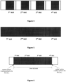
- the field of time domain resource assignment may be set to "common" for all of the scheduled multiple slots. For example, as shown in Figure 4 , assuming four slots are scheduled by a single UL grant, when the time domain resource assignment in the UL grant indicates the row index 6 of Table 3, then the starting symbol and ending symbol are symbol 4 and symbol 11 (calculated by 4+8-1). If the field of time domain resource assignment is set to common for the four scheduled slots, then the starting symbol and ending symbol for all of the first to fourth slots are 4 and 11, respectively. Thus, transmission gaps are formed between the first slot and the second slot, between the second slot and the third slot, and between the third slot and the fourth slot.
- non-contiguous time domain resource allocation is caused.
- This non-contiguous time domain resource allocation is not suitable for burst based transmission on unlicensed spectrum because LBT is needed for each of the multiple scheduled slots. That means that any transmission gap bears the risk of 'losing' the channel to another node that sensed the channel to be idle in such a gap and henceforth starts its own transmission.
- a multiple full slot scheduling may be used as shown in Figure 5 .
- the scheduling flexibility is restricted since the multiple scheduled slots have to start from the symbol 0.
- Table 3 Default PUSCH time domain resource allocation Row index PUSCH mapping type K L S L 1 Type A j 0 14 2 Type A j 0 12 3 Type A j 0 10 4 Type B j 2 10 5 Type B j 4 10 6 Type B j 4 8 7 Type B j 4 6 8 Type A j +1 0 14 9 Type A j +1 0 12 10 Type A j +1 0 10 11 Type A j +2 0 14 12 Type A j +2 0 12 13 Type A j +2 0 10 14 Type B j 8 6 15 Type A j +3 0 14 16 Type A j +3 0 10 Table 4: Definition of value j ⁇ PUSCH j 0 1 1 1 2 2 3 3 3
- S represents the starting position
- L represents the duration
- K2 represents slot level offset between the slot where UL grant is received and the slot where associated PUSCH is scheduled.
- ⁇ PUSCH is the subcarrier spacing. Different subcarrier spacing values correspond to different values of K2. So, j is used to indicate such difference.
- Modules may also be implemented in code and/or software for execution by various types of processors.
- An identified module of code may, for instance, include one or more physical or logical blocks of executable code which may, for instance, be organized as an object, procedure, or function. Nevertheless, the executables of an identified module need not be physically located together, but, may include disparate instructions stored in different locations which, when joined logically together, include the module and achieve the stated purpose for the module.
- a module of code may be a single instruction, or many instructions, and may even be distributed over several different code segments, among different programs, and across several memory devices.
- operational data may be identified and illustrated herein within modules and may be embodied in any suitable form and organized within any suitable type of data structure. This operational data may be collected as a single data set, or may be distributed over different locations including over different computer readable storage devices.
- the software portions are stored on one or more computer readable storage devices.
- the computer readable medium may be a computer readable storage medium.
- the computer readable storage medium may be a storage device storing code.
- the storage device may be, for example, but need not necessarily be, an electronic, magnetic, optical, electromagnetic, infrared, holographic, micromechanical, or semiconductor system, apparatus, or device, or any suitable combination of the foregoing.
- Code for carrying out operations for embodiments may be any number of lines and may be written in any combination of one or more programming languages including an object-oriented programming language such as Python, Ruby, Java, Smalltalk, C++, or the like, and conventional procedural programming languages, such as the "C" programming language, or the like, and/or machine languages such as assembly languages.
- the code may be executed entirely on the user's computer, partly on the user's computer, as a stand-alone software package, partly on the user's computer and partly on a remote computer or entirely on the remote computer or server.
- the remote computer may be connected to the user's computer through any type of network, including a local area network (LAN) or a wide area network (WAN), or the connection may be made to an external computer (for example, through the Internet using an Internet Service Provider).
- LAN local area network
- WAN wide area network
- the code may also be stored in a storage device that can direct a computer, other programmable data processing apparatus, or other devices, to function in a particular manner, such that the instructions stored in the storage device produce an article of manufacture including instructions which implement the function specified in the schematic flowchart diagrams and/or schematic block diagrams block or blocks.
- the code may also be loaded onto a computer, other programmable data processing apparatus, or other devices, to cause a series of operational steps to be performed on the computer, other programmable apparatus or other devices to produce a computer implemented process such that the code executed on the computer or other programmable apparatus provides processes for implementing the functions specified in the flowchart and/or block diagram block or blocks.
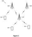
- Figure 1 depicts an embodiment of a wireless communication system 100 for multi-slot scheduling on unlicensed spectrum.
- the wireless communication system 100 includes remote units 102 and base units 104. Even though a specific number of remote units 102 and base units 104 are depicted in Figure 1 , one skilled in the art will recognize that any number of remote units 102 and base units 104 may be included in the wireless communication system 100.
- the remote units 102 may include computing devices, such as desktop computers, laptop computers, personal digital assistants (PDAs), tablet computers, smart phones, smart televisions (e.g., televisions connected to the Internet), set-top boxes, game consoles, security systems (including security cameras), vehicle on-board computers, network devices (e.g., routers, switches, modems), or the like.
- the remote units 102 include wearable devices, such as smart watches, fitness bands, optical head-mounted displays, or the like.
- the remote units 102 may be referred to as subscriber units, mobiles, mobile stations, users, terminals, mobile terminals, fixed terminals, subscriber stations, user equipment (UE), user terminals, a device, or by other terminology used in the art.
- the remote units 102 may communicate directly with one or more of the base units 104 via UL communication signals.
- the base units 104 may be distributed over a geographic region.
- a base unit 104 may also be referred to as an access point, an access terminal, a base, a base station, a Node-B, an eNB, a gNB, a Home Node-B, a relay node, a device, or by any other terminology used in the art.
- the base units 104 are generally part of a radio access network that includes one or more controllers communicably coupled to one or more corresponding base units 104.
- the radio access network is generally communicably coupled to one or more core networks, which may be coupled to other networks, like the Internet and public switched telephone networks, among other networks. These and other elements of radio access and core networks are not illustrated, but are well known generally by those having ordinary skill in the art.
- the wireless communication system 100 is compliant with 3GPP 5G new radio (NR). More generally, however, the wireless communication system 100 may implement some other open or proprietary communication protocol.
- NR 3GPP 5G new radio
- the base units 104 may serve a number of remote units 102 within a serving area, for example, a cell (or a cell sector) or more cells via a wireless communication link.
- the base units 104 transmit DL communication signals to serve the remote units 102 in the time, frequency, and/or spatial domain.
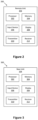
- Figure 2 depicts one embodiment of an apparatus 200 that may be used for multi-slot scheduling on unlicensed spectrum.
- the apparatus 200 includes one embodiment of the remote unit 102.
- the remote unit 102 may include a processor 202, a memory 204, an input device 206, a display 208, a transmitter 210, and a receiver 212.
- the input device 206 and the display 208 are combined into a single device, such as a touch screen.
- the remote unit 102 may not include any input device 206 and/or display 208.
- the remote unit 102 may include at least one of the processor 202, the memory 204, the transmitter 210 and the receiver 212, and may not include the input device 206 and/or the display 208.
- the processor 202 may include any known controller capable of executing computer-readable instructions and/or capable of performing logical operations.
- the processor 202 may be a microcontroller, a microprocessor, a central processing unit (CPU), a graphics processing unit (GPU), an auxiliary processing unit, a field programmable gate array (FPGA), or similar programmable controller.
- the processor 202 executes instructions stored in the memory 204 to perform the methods and routines described herein.
- the processor 202 is communicatively coupled to the memory 204, the input device 206, the display 208, the transmitter 210, and the receiver 212.
- the memory 204 in one embodiment, is a computer readable storage medium.
- the memory 204 includes volatile computer storage media.
- the memory 204 may include a RAM, including dynamic RAM (DRAM), synchronous dynamic RAM (SDRAM), and/or static RAM (SRAM).
- the memory 204 includes non-volatile computer storage media.
- the memory 204 may include a hard disk drive, a flash memory, or any other suitable non-volatile computer storage device.
- the memory 204 includes both volatile and non-volatile computer storage media.
- the memory 204 stores data relating to system parameters.
- the memory 204 also stores program code and related data, such as an operating system or other controller algorithms operating on the remote unit 102.
- the input device 206 may include any known computer input device including a touch panel, a button, a keyboard, a stylus, a microphone, or the like.
- the input device 206 may be integrated with the display 208, for example, as a touch screen or similar touch-sensitive display.
- the input device 206 includes a touch screen such that text may be input using a virtual keyboard displayed on the touch screen and/or by handwriting on the touch screen.
- the input device 206 includes two or more different devices, such as a keyboard and a touch panel.
- the display 208 may include any known electronically controllable display or display device.
- the display 208 may be designed to output visual, audible, and/or haptic signals.
- the display 208 includes an electronic display capable of outputting visual data to a user.
- the display 208 may include, but is not limited to, an LCD display, an LED display, an OLED display, a projector, or similar display device capable of outputting images, text, or the like to a user.
- the display 208 may include a wearable display such as a smart watch, smart glasses, a heads-up display, or the like.
- the display 208 may be a component of a smart phone, a personal digital assistant, a television, a table computer, a notebook (laptop) computer, a personal computer, a vehicle dashboard, or the like.
- the display 208 includes one or more speakers for producing sound.
- the display 208 may produce an audible alert or notification (e.g., a beep or chime).
- the display 208 includes one or more haptic devices for producing vibrations, motion, or other haptic feedback.
- all or portions of the display 208 may be integrated with the input device 206.
- the input device 206 and display 208 may form a touch screen or similar touch-sensitive display.
- the display 208 may be located near the input device 206.
- the transmitter 210 is used to provide UL communication signals to the base unit 104 and the receiver 212 is used to receive DL communication signals from the base unit 104.
- the transmitter 210 and the receiver 212 may transmit and receive resources via different cells.
- the remote unit 102 may have any suitable number of transmitters 210 and receivers 212.
- the transmitter 210 and the receiver 212 may be any suitable type of transmitters and receivers.
- the transmitter 210 and the receiver 212 may be part of a transceiver.
- Figure 3 depicts one embodiment of another apparatus 300 that may be used for multi-slot scheduling on unlicensed spectrum.
- the apparatus 300 includes one embodiment of the base unit 104.
- the base unit 104 may include at least one of a processor 302, a memory 304, an input device 306, a display 308, a transmitter 310 and a receiver 312.
- the processor 302, the memory 304, the input device 306, the display 308, the transmitter 310, and the receiver 312 may be substantially similar to the processor 202, the memory 204, the input device 206, the display 208, the transmitter 210, and the receiver 212 of the remote unit 102, respectively.
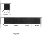
- Figure 6 illustrate a schematic view of a time-contiguous domain resource allocation for multiple slots scheduled by a single UL grant.
- the time-contiguous domain resource allocation for multiple UL slots is labeled as one UL burst.
- the time-contiguous domain resource may start from any symbol in the first slot, and end at any symbol in the last slot.
- the multiple slots scheduled by a single UL grant may be any integer, and preferably be 2 or more.
- Figure 6 shows that the total scheduled slots are four.
- the slots between the first slot and the last slot are referred to as the middle slots.
- the second slot and the third slot are middle slots.
- the number of middle slots equals the total scheduled slots minus 2. Therefore, in the situation that the total scheduled slots are 2 slots, the number of middle slots is zero.
- all of the symbols (Symbol 0 to Symbol 13) in each of the middle slots have to be fully scheduled.
- Both the existing PUSCH mapping type A and type B may be used to indicate time domain resource allocation for a single slot.
- a new PUSCH mapping type C is introduced to indicate time domain resource allocation for multiple slots.
- the starting position refers to a starting symbol in the first slot. Since the starting position is always in the first slot (in other words, the index of the first slot is always 1), it is enough to determine the starting position according to the starting symbol.
- the ending position refers to an ending symbol in the last slot. The ending position is determined according to an index of the last slot and the ending symbol in the last slot.
- the index of the last slot may be calculated based on the number of scheduled slots. In particular, the index of the last slot equals the number of scheduled slots. In the example of Figure 6 , the index of the last slot is 4.
- a starting symbol in the first slot, an ending symbol in the last slot and the number of total scheduled slots are used for indicating the starting position and the ending position of the allocated resource.
- the starting symbol in the first slot is selected from a set of starting symbols.
- the ending symbol in the last slot is selected from a set of ending symbols.
- the set of starting symbols and the set of ending symbols are configured by RRC signaling.
- the number of total scheduled slots is a number that is no more than the maximum number of slots scheduled by a single UL grant.
- the maximum number of slots scheduled by a single UL grant may be configured by RRC signaling.
- UE Upon receiving an indication of a starting symbol in the first slot, the indication of the ending symbol in the last slot, as well as the total number of scheduled slots as part of the received UL grant, UE knows the time domain resource allocation for the multiple slots, i.e. the starting position and the ending position of the allocated resource.
- a starting symbol in the first slot, an ending symbol in the last slot and the total number of scheduled slots are used for indicating the starting position and the ending position of the allocated resource; and the starting symbol in the first slot and the ending symbol in the last slot are selected, respectively from a set of starting symbols and a set of ending symbols.
- the second alternative implementation differs from the first alternative implementation in that the starting symbols and ending symbols for PUSCH mapping type B shown in Table 2 are chosen as a set of starting symbols and a set of ending symbols. In this way, the RRC signaling for configuring the set of starting symbols and the set of ending symbols is not needed.
- the number of scheduled slots is indicated in the UL grant.
- the number of scheduled middle slots may be indicated in the UL grant. Due to the requirement of time-contiguous domain allocation, only the first slot and the final slot may be a partial slot, which means the starting symbol in the first slot is after symbol 0 or the ending symbol in the final slot is before symbol 13. On the other hand, all of the middle slots that are between the first slot and the final slot have to be full, which means that the starting symbol in each middle slot is always symbol 0 and the ending symbol of each middle slot is always symbol 13. So, if the UL grant is used for scheduling minimum 2 slots, then there is no ambiguity for UE to determine the time domain resource allocation when the number of scheduled middle slots is indicated.
- the total number of actually scheduled slots can be minimum 2 slots and maximum N slots.
- N is configured to 5
- 2 bits can be used to indicate 0, 1, 2 or 3 scheduled middle slots.
- the total number of scheduled slots can be 2, 3, 4 or 5.
- a new PUSCH mapping type C is introduced to indicate time-contiguous resource allocation for multiple slots.
- the existing PUSCH mapping type A and type B are used in combination to indicate time-contiguous domain resource allocation for multiple slots.
- the time-contiguous resource allocation for multi-slot transmission includes four cases: (1) all the slots are full slots; (2) the first slot is a partial slot and all the remaining slots are full slots; (3) the first to the last second slots are full slots and the last slot is a partial slot; (4) the first slot and the last slot are partial slots and all the middle slots are full slots.
- a full slot means that the starting symbol is symbol 0 and the ending symbol is symbol 13.
- a partial slot includes three cases: in a first case, the starting symbol is after symbol 0 and the ending symbol is Symbol 13; in a second case, the starting symbol is Symbol 0 and the ending symbol is before Symbol 13; in a third case, the starting symbol is after Symbol 0 and the ending symbol is before symbol 13.
- the first slot should be scheduled as PUSCH mapping type B since it doesn't start from symbol 0 and all the other slots are full slots and can be scheduled as PUSCH mapping type A since all the other slots start from symbol 0 and occupy 14 symbols.
- all the other slots may be scheduled as PUSCH mapping type B since PUSCH mapping type B may start from Symbol 0 and end at any symbol (including Symbol 13) within one slot.
- the last slot may be scheduled as PUSCH mapping type A if the last slot occupies at least 4 symbols or scheduled as PUSCH mapping type B. All the other slots are full slots and may be scheduled as PUSCH mapping type A or PUSCH mapping type B.
- the last slot may be scheduled as PUSCH mapping type A if the last slot occupies at least 4 symbols or scheduled as PUSCH mapping type B.
- the first slot should be scheduled as PUSCH mapping type B since it doesn't start from symbol 0. All the middle slots are full slots and may be scheduled as PUSCH mapping type A or PUSCH mapping type B.
- PUSCH mapping type A and/or PUSCH mapping type B may be used individually or in combination to schedule a time-contiguous resource allocation for multi-slot transmission.
- PUSCH mapping type A and/or PUSCH mapping type B may be used individually or in combination to schedule a time-contiguous resource allocation for multi-slot transmission.
- mapping type may be specified for the first slot and the last slot. All the middle slots may be fixed to mapping type A or type B.
- mapping type may be specified for the first slot and the middle slots.
- the last slot may use mapping type A if the last slot occupies at least 4 symbols and use mapping type B if the last slot occupies 1, 2 or 3 symbols.
- mapping type may be specified only for the last slot.
- the first slot uses mapping type A if it starts from symbol 0 and use mapping type B if it starts from any of symbols 1 to 12. All the middle slots may be fixed to mapping type A or type B.
- the first slot may use mapping type A if it starts from symbol 0 and use mapping type B if it starts from any of symbols 1 to 12. All the middle slots may be fixed to mapping type A or type B.
- the last slot may use mapping type A if the last slot occupies at least 4 symbols and use mapping type B if the last slot occupies 1, 2 or 3 symbols.
- the base unit transmits a downlink control information (DCI) for scheduling time-contiguous data transmission in multiple slots to a remote unit, wherein the DCI includes an indicator indicating time domain resource allocation in the multiple slots.
- DCI downlink control information
- the remote unit receives the DCI for scheduling time-contiguous data transmission in multiple slots.
- the remote unit determines a starting position and an ending position of the scheduled time-contiguous data transmission, based on the indicator included in the DCI.
- step 8230 the remote unit, in response to a successful listen before talk (LBT), transmits data from the determined starting position to the determined ending position.
- LBT listen before talk
- step 8120 the base unit receives the data from the starting position to the ending position.
Landscapes
- Engineering & Computer Science (AREA)
- Computer Networks & Wireless Communication (AREA)
- Signal Processing (AREA)
- Mobile Radio Communication Systems (AREA)
Claims (13)
- Verfahren, das durch eine entfernte Einheit durchgeführt wird, umfassend:Empfangen (8210) von Downlink-Steuerinformationen, DCI, zum Planen einer zeitlich zusammenhängenden Datensendung in mehreren Schlitzen, wobei die DCI einen Indikator, der die Zeitbereichsressourcenzuweisung in den mehreren Schlitzen angibt, einschließen;Bestimmen (8220), basierend auf dem Indikator, einer Startposition und einer Endposition der geplanten zeitlich zusammenhängenden Datensendung; undSenden (8230) von Daten von der bestimmten Startposition zu der bestimmten Endposition; wobei die Daten als Reaktion auf erfolgreiches Listen-Before-Talk, LBT, gesendet werden, und dadurch gekennzeichnet, dassder Indikator separate Angaben zu PUSCH-Zuordnungsarten für einen ersten Schlitz, einen letzten Schlitz und einen mittleren Schlitz bzw. mittlere Schlitze der mehreren Schlitze einschließt.
- Verfahren nach Anspruch 1, wobei der Indikator ein Startsymbol in einem ersten Schlitz der mehreren Schlitze angibt.
- Verfahren nach Anspruch 2, wobei das Startsymbol in dem ersten Schlitz aus einem Satz möglicher Startsymbole, die durch eine Funkressourcensteuerungssignalisierung, RRC-Signalisierung, konfiguriert sind, ausgewählt ist oder wobei das Startsymbol in dem ersten Schlitz aus einem Satz möglicher Startsymbole einer Zuordnungsart B eines gemeinsam genutzten physikalischen Uplink-Kanals, PUSCH, ausgewählt ist.
- Verfahren nach Anspruch 1, wobei ein Startsymbol in einem ersten Schlitz der mehreren Schlitze auf Symbol 0 festgelegt ist.
- Verfahren nach Anspruch 1, wobei der Indikator ein Endsymbol eines letzten Schlitzes der mehreren Schlitze angibt.
- Verfahren nach Anspruch 5, wobei das Endsymbol des letzten Schlitzes aus einem Satz möglicher Endsymbole, die durch die Funkressourcensteuerungssignalisierung, RRC-Signalisierung, konfiguriert sind, ausgewählt ist oder wobei das Endsymbol des letzten Schlitzes aus einem Satz möglicher Endsymbole der Zuordnungsart B des gemeinsam genutzten physikalischen Uplink-Kanals, PUSCH, ausgewählt ist.
- Verfahren nach Anspruch 1, wobei der Indikator:die Anzahl der mehreren Schlitze angibt;die Anzahl voller Schlitze; odereinen Startsymbolindex in einem ersten Schlitz der mehreren Schlitze und eine Differenz zwischen dem Startsymbolindex und einem Endsymbolindex eines letzten Schlitzes der mehreren Schlitze angibt.
- Verfahren nach Anspruch 2, wobei der Indikator ferner eine Dauer der geplanten Symbole in den mehreren Schlitzen angibt.
- Verfahren nach Anspruch 1, wobei der Indikator einen Startsymbolindex in einem ersten Schlitz der mehreren Schlitze und eine Dauer in einer Anzahl von Symbolen in einem letzten Schlitz der mehreren Schlitze angibt.
- Verfahren nach Anspruch 1, wobei der Indikator separate Angaben einschließt, um die Startposition beziehungsweise die Endposition anzugeben.
- Verfahren, das durch eine Basisstation durchgeführt wird, umfassend:Senden von Downlink-Steuerinformationen, DCI, zu einer entfernten Einheit zum Planen der zeitlich zusammenhängenden Datensendung in mehreren Schlitzen, wobei die DCI einen Indikator, der die Zeitbereichsressourcenzuweisung in den mehreren Schlitzen angibt, einschließen; undEmpfangen, von der entfernten Einheit, von Daten von einer Startposition zu einer Endposition, die aus der angegebenen Zeitbereichsressourcenzuweisung in den mehreren Schlitzen bestimmt werden; wobei die Daten von der entfernten Einheit als Reaktion auf ein erfolgreiches Listen-Before-Talk, LBT, empfangen werden, und dadurch gekennzeichnet, dassder Indikator separate Angaben zu PUSCH-Zuordnungsarten für einen ersten Schlitz, einen letzten Schlitz und einen mittleren Schlitz bzw. mittlere Schlitze der mehreren Schlitze einschließt.
- Vorrichtung für eine entfernte Einheit, umfassend:einen Empfänger (212), der eingerichtet ist, um Downlink-Steuerinformationen, DCI, zum Planen der zeitlich zusammenhängenden Datensendung in mehreren Schlitzen zu empfangen, wobei die DCI einen Indikator, der die Zeitbereichsressourcenzuweisung in den mehreren Schlitzen angibt, einschließen;einen Prozessor (202), der eingerichtet ist, um, basierend auf dem Indikator, eine Startposition und eine Endposition der geplanten zeitlich zusammenhängenden Datensendung zu bestimmen; undeinen Sender (210), der eingerichtet ist, um Daten von der bestimmten Startposition zu der bestimmten Endposition zu senden; wobei der Sender (210) eingerichtet ist, um die Daten als Reaktion auf ein erfolgreiches Listen-Before-Talk, LBT, zu senden, und dadurch gekennzeichnet, dass der Indikator separate Angaben zu PUSCH-Zuordnungsarten für einen ersten Schlitz, einen letzten Schlitz und einen mittleren Schlitz bzw. mittlere Schlitze der mehreren Schlitze einschließt.
- Vorrichtung für eine Basisstation, umfassend:einen Sender (312), der eingerichtet ist, um Downlink-Steuerinformationen, DCI, zu einer entfernten Einheit zum Planen der zeitlich zusammenhängenden Datensendung in mehreren Schlitzen zu senden, wobei die DCI einen Indikator, der die Zeitbereichsressourcenzuweisung in den mehreren Schlitzen angibt, einschließen, wobei der Indikator separate Angaben zu PUSCH-Zuordnungsarten für einen ersten Schlitz, einen letzten Schlitz und einen mittleren Schlitz bzw. mittlere Schlitze der mehreren Schlitzen einschließt; undeinen Empfänger (312), der eingerichtet ist, um, von der entfernten Einheit, Daten von einer Startposition zu einer Endposition zu empfangen, die aus der angegebenen Zeitbereichsressourcenzuweisung in den mehreren Schlitzen bestimmt werden; wobei der Empfänger (312) eingerichtet ist, um die Daten von der entfernten Einheit als Reaktion auf ein erfolgreiches Listen-Before-Talk, LBT, zu empfangen, unddadurch gekennzeichnet, dass der Indikator separate Angaben zu PUSCH-Zuordnungsarten für einen ersten Schlitz, einen letzten Schlitz und einen mittleren Schlitz bzw. mittlere Schlitze der mehreren Schlitze einschließt.
Applications Claiming Priority (1)
| Application Number | Priority Date | Filing Date | Title |
|---|---|---|---|
| PCT/CN2018/108282 WO2020062011A1 (en) | 2018-09-28 | 2018-09-28 | Multi-slot scheduling on unlicensed spectrum |
Publications (4)
| Publication Number | Publication Date |
|---|---|
| EP3858019A1 EP3858019A1 (de) | 2021-08-04 |
| EP3858019A4 EP3858019A4 (de) | 2022-05-11 |
| EP3858019B1 true EP3858019B1 (de) | 2025-07-09 |
| EP3858019C0 EP3858019C0 (de) | 2025-07-09 |
Family
ID=69950949
Family Applications (1)
| Application Number | Title | Priority Date | Filing Date |
|---|---|---|---|
| EP18934727.1A Active EP3858019B1 (de) | 2018-09-28 | 2018-09-28 | Mehrschlitzplanung auf unlizenziertem spektrum |
Country Status (5)
| Country | Link |
|---|---|
| US (1) | US12232124B2 (de) |
| EP (1) | EP3858019B1 (de) |
| CN (1) | CN112889327A (de) |
| ES (1) | ES3035818T3 (de) |
| WO (1) | WO2020062011A1 (de) |
Families Citing this family (6)
| Publication number | Priority date | Publication date | Assignee | Title |
|---|---|---|---|---|
| CN118631407A (zh) * | 2018-08-10 | 2024-09-10 | 苹果公司 | 用于新无线电超可靠低延时通信的物理上行链路共享信道增强 |
| CN111343718B (zh) * | 2018-12-18 | 2022-09-09 | 北京紫光展锐通信技术有限公司 | 占有时隙的确定方法及装置、存储介质、用户终端 |
| CN113424581B (zh) * | 2019-02-14 | 2025-05-13 | 中兴通讯股份有限公司 | 数据传输 |
| CN114696979B (zh) * | 2020-12-31 | 2024-11-26 | 维沃移动通信有限公司 | 信道的调度方法及通信设备 |
| CN119605134A (zh) * | 2022-08-11 | 2025-03-11 | 高通股份有限公司 | 针对未许可频谱中的侧链路通信的配置准予增强 |
| CN120034976A (zh) * | 2023-11-23 | 2025-05-23 | 华为技术有限公司 | 一种通信方法及装置 |
Family Cites Families (12)
| Publication number | Priority date | Publication date | Assignee | Title |
|---|---|---|---|---|
| CN102404074B (zh) | 2010-09-17 | 2014-06-18 | 电信科学技术研究院 | Tdd系统中的非周期srs的传输方法和设备 |
| CN111740812B (zh) * | 2016-04-01 | 2022-09-20 | 中兴通讯股份有限公司 | 探测参考信号发送方法 |
| CN107370589B (zh) | 2016-05-13 | 2023-04-07 | 中兴通讯股份有限公司 | 信号传输方法、装置及用户设备 |
| US11076388B2 (en) * | 2017-01-13 | 2021-07-27 | Qualcomm Incorporated | Configurable common uplink burst length |
| US20210144757A1 (en) * | 2017-06-23 | 2021-05-13 | Idac Holdings, Inc. | Transmission with restrictions in unlicensed spectrum |
| JP6861891B2 (ja) * | 2017-09-11 | 2021-04-21 | エルジー エレクトロニクス インコーポレイティド | 無線通信システムにおけるダウンリンク制御情報を送信する方法及び装置 |
| US10512072B2 (en) * | 2017-09-11 | 2019-12-17 | Lg Electronics Inc. | Method and apparatus for transmitting downlink control information in wireless communication system |
| WO2019074414A1 (en) * | 2017-10-13 | 2019-04-18 | Telefonaktiebolaget Lm Ericsson (Publ) | RECEIVE ACCUSED SIGNALING METHOD FOR RADIO ACCESS NETWORKS |
| EP3484088B1 (de) * | 2017-11-13 | 2021-11-03 | ASUSTek Computer Inc. | Verfahren und vorrichtung zur anzeige einer zeitbereichsressourcenzuweisung einer datenübertragung in einem drahtloskommunikationssystem |
| KR102777983B1 (ko) * | 2018-07-26 | 2025-03-10 | 삼성전자주식회사 | 무선 통신 시스템에서 자원을 할당하는 방법, 장치 및 시스템 |
| US11153872B2 (en) * | 2018-07-31 | 2021-10-19 | Asustek Computer Inc. | Method and apparatus for indicating slot format of an unlicensed cell in a wireless communication system |
| PL3834337T3 (pl) | 2018-08-10 | 2023-08-28 | Telefonaktiebolaget Lm Ericsson (Publ) | Przyznanie szeregowania łącza wstępującego dla wielu fizycznych kanałów współdzielonych łącza wstępującego |
-
2018
- 2018-09-28 EP EP18934727.1A patent/EP3858019B1/de active Active
- 2018-09-28 ES ES18934727T patent/ES3035818T3/es active Active
- 2018-09-28 US US17/276,129 patent/US12232124B2/en active Active
- 2018-09-28 CN CN201880098024.1A patent/CN112889327A/zh active Pending
- 2018-09-28 WO PCT/CN2018/108282 patent/WO2020062011A1/en not_active Ceased
Non-Patent Citations (1)
| Title |
|---|
| SHARP: "HARQ enhancement for NR unlicensed operation", vol. RAN WG1, no. Chongqing, China; 20191014 - 20191020, 8 October 2019 (2019-10-08), XP051809235, Retrieved from the Internet <URL:https://ftp.3gpp.org/tsg_ran/WG1_RL1/TSGR1_98b/Docs/R1-1910931.zip R1-1910931.docx> [retrieved on 20191008] * |
Also Published As
| Publication number | Publication date |
|---|---|
| WO2020062011A1 (en) | 2020-04-02 |
| EP3858019A1 (de) | 2021-08-04 |
| US20220053541A1 (en) | 2022-02-17 |
| EP3858019C0 (de) | 2025-07-09 |
| EP3858019A4 (de) | 2022-05-11 |
| ES3035818T3 (en) | 2025-09-09 |
| CN112889327A (zh) | 2021-06-01 |
| US12232124B2 (en) | 2025-02-18 |
Similar Documents
| Publication | Publication Date | Title |
|---|---|---|
| US11968687B2 (en) | Scheduling of transmission time intervals | |
| US12143972B2 (en) | Apparatus and method of scheduling Multi-TTI transmissions | |
| US11825478B2 (en) | Uplink/downlink scheduling in a wireless communication system | |
| EP3858019B1 (de) | Mehrschlitzplanung auf unlizenziertem spektrum | |
| US20240250779A1 (en) | Harq-ack transmission on unlicensed spectrum | |
| WO2022175894A1 (en) | Configuring a sidelink resource pool | |
| US12119969B2 (en) | Non-anchor carrier frequency offset indication | |
| US11456816B2 (en) | Flexible uplink/downlink transmissions in a wireless communication system | |
| US20240314777A1 (en) | Retransmitting portions of a transport block | |
| US20220216968A1 (en) | Srs configurations and srs transmission | |
| US12200700B2 (en) | Time domain resource allocation |
Legal Events
| Date | Code | Title | Description |
|---|---|---|---|
| STAA | Information on the status of an ep patent application or granted ep patent |
Free format text: STATUS: THE INTERNATIONAL PUBLICATION HAS BEEN MADE |
|
| PUAI | Public reference made under article 153(3) epc to a published international application that has entered the european phase |
Free format text: ORIGINAL CODE: 0009012 |
|
| STAA | Information on the status of an ep patent application or granted ep patent |
Free format text: STATUS: REQUEST FOR EXAMINATION WAS MADE |
|
| 17P | Request for examination filed |
Effective date: 20210312 |
|
| AK | Designated contracting states |
Kind code of ref document: A1 Designated state(s): AL AT BE BG CH CY CZ DE DK EE ES FI FR GB GR HR HU IE IS IT LI LT LU LV MC MK MT NL NO PL PT RO RS SE SI SK SM TR |
|
| DAV | Request for validation of the european patent (deleted) | ||
| DAX | Request for extension of the european patent (deleted) | ||
| A4 | Supplementary search report drawn up and despatched |
Effective date: 20220408 |
|
| RIC1 | Information provided on ipc code assigned before grant |
Ipc: H04W 74/08 20090101ALN20220404BHEP Ipc: H04W 72/04 20090101AFI20220404BHEP |
|
| STAA | Information on the status of an ep patent application or granted ep patent |
Free format text: STATUS: EXAMINATION IS IN PROGRESS |
|
| 17Q | First examination report despatched |
Effective date: 20240718 |
|
| REG | Reference to a national code |
Ref country code: DE Ref legal event code: R079 Free format text: PREVIOUS MAIN CLASS: H04W0072040000 Ipc: H04W0072044600 Ref country code: DE Ref legal event code: R079 Ref document number: 602018083533 Country of ref document: DE Free format text: PREVIOUS MAIN CLASS: H04W0072040000 Ipc: H04W0072044600 |
|
| GRAP | Despatch of communication of intention to grant a patent |
Free format text: ORIGINAL CODE: EPIDOSNIGR1 |
|
| STAA | Information on the status of an ep patent application or granted ep patent |
Free format text: STATUS: GRANT OF PATENT IS INTENDED |
|
| INTG | Intention to grant announced |
Effective date: 20250210 |
|
| RIC1 | Information provided on ipc code assigned before grant |
Ipc: H04W 72/23 20230101ALN20250131BHEP Ipc: H04W 74/0808 20240101ALN20250131BHEP Ipc: H04W 72/0446 20230101AFI20250131BHEP |
|
| GRAS | Grant fee paid |
Free format text: ORIGINAL CODE: EPIDOSNIGR3 |
|
| GRAA | (expected) grant |
Free format text: ORIGINAL CODE: 0009210 |
|
| STAA | Information on the status of an ep patent application or granted ep patent |
Free format text: STATUS: THE PATENT HAS BEEN GRANTED |
|
| AK | Designated contracting states |
Kind code of ref document: B1 Designated state(s): AL AT BE BG CH CY CZ DE DK EE ES FI FR GB GR HR HU IE IS IT LI LT LU LV MC MK MT NL NO PL PT RO RS SE SI SK SM TR |
|
| REG | Reference to a national code |
Ref country code: GB Ref legal event code: FG4D |
|
| REG | Reference to a national code |
Ref country code: CH Ref legal event code: EP |
|
| REG | Reference to a national code |
Ref country code: IE Ref legal event code: FG4D |
|
| REG | Reference to a national code |
Ref country code: DE Ref legal event code: R096 Ref document number: 602018083533 Country of ref document: DE |
|
| U01 | Request for unitary effect filed |
Effective date: 20250725 |
|
| U07 | Unitary effect registered |
Designated state(s): AT BE BG DE DK EE FI FR IT LT LU LV MT NL PT RO SE SI Effective date: 20250801 |
|
| REG | Reference to a national code |
Ref country code: ES Ref legal event code: FG2A Ref document number: 3035818 Country of ref document: ES Kind code of ref document: T3 Effective date: 20250909 |
|
| PGFP | Annual fee paid to national office [announced via postgrant information from national office to epo] |
Ref country code: GB Payment date: 20250923 Year of fee payment: 8 |
|
| U20 | Renewal fee for the european patent with unitary effect paid |
Year of fee payment: 8 Effective date: 20250929 |
|
| PG25 | Lapsed in a contracting state [announced via postgrant information from national office to epo] |
Ref country code: IS Free format text: LAPSE BECAUSE OF FAILURE TO SUBMIT A TRANSLATION OF THE DESCRIPTION OR TO PAY THE FEE WITHIN THE PRESCRIBED TIME-LIMIT Effective date: 20251109 |
|
| PG25 | Lapsed in a contracting state [announced via postgrant information from national office to epo] |
Ref country code: NO Free format text: LAPSE BECAUSE OF FAILURE TO SUBMIT A TRANSLATION OF THE DESCRIPTION OR TO PAY THE FEE WITHIN THE PRESCRIBED TIME-LIMIT Effective date: 20251009 |
|
| PG25 | Lapsed in a contracting state [announced via postgrant information from national office to epo] |
Ref country code: HR Free format text: LAPSE BECAUSE OF FAILURE TO SUBMIT A TRANSLATION OF THE DESCRIPTION OR TO PAY THE FEE WITHIN THE PRESCRIBED TIME-LIMIT Effective date: 20250709 |
|
| PG25 | Lapsed in a contracting state [announced via postgrant information from national office to epo] |
Ref country code: GR Free format text: LAPSE BECAUSE OF FAILURE TO SUBMIT A TRANSLATION OF THE DESCRIPTION OR TO PAY THE FEE WITHIN THE PRESCRIBED TIME-LIMIT Effective date: 20251010 |
|
| PG25 | Lapsed in a contracting state [announced via postgrant information from national office to epo] |
Ref country code: PL Free format text: LAPSE BECAUSE OF FAILURE TO SUBMIT A TRANSLATION OF THE DESCRIPTION OR TO PAY THE FEE WITHIN THE PRESCRIBED TIME-LIMIT Effective date: 20250709 |
|
| PG25 | Lapsed in a contracting state [announced via postgrant information from national office to epo] |
Ref country code: RS Free format text: LAPSE BECAUSE OF FAILURE TO SUBMIT A TRANSLATION OF THE DESCRIPTION OR TO PAY THE FEE WITHIN THE PRESCRIBED TIME-LIMIT Effective date: 20251009 |
|
| PGFP | Annual fee paid to national office [announced via postgrant information from national office to epo] |
Ref country code: ES Payment date: 20251015 Year of fee payment: 8 |
|
| PG25 | Lapsed in a contracting state [announced via postgrant information from national office to epo] |
Ref country code: SM Free format text: LAPSE BECAUSE OF FAILURE TO SUBMIT A TRANSLATION OF THE DESCRIPTION OR TO PAY THE FEE WITHIN THE PRESCRIBED TIME-LIMIT Effective date: 20250709 |
|
| PG25 | Lapsed in a contracting state [announced via postgrant information from national office to epo] |
Ref country code: CZ Free format text: LAPSE BECAUSE OF FAILURE TO SUBMIT A TRANSLATION OF THE DESCRIPTION OR TO PAY THE FEE WITHIN THE PRESCRIBED TIME-LIMIT Effective date: 20250709 |
|
| PG25 | Lapsed in a contracting state [announced via postgrant information from national office to epo] |
Ref country code: SK Free format text: LAPSE BECAUSE OF FAILURE TO SUBMIT A TRANSLATION OF THE DESCRIPTION OR TO PAY THE FEE WITHIN THE PRESCRIBED TIME-LIMIT Effective date: 20250709 |