EP3858037B1 - Signalisation d'un retard minimal d'ordonnancement - Google Patents
Signalisation d'un retard minimal d'ordonnancement Download PDFInfo
- Publication number
- EP3858037B1 EP3858037B1 EP19789817.4A EP19789817A EP3858037B1 EP 3858037 B1 EP3858037 B1 EP 3858037B1 EP 19789817 A EP19789817 A EP 19789817A EP 3858037 B1 EP3858037 B1 EP 3858037B1
- Authority
- EP
- European Patent Office
- Prior art keywords
- minimum threshold
- scheduling
- pdcch
- transmission
- minimum
- Prior art date
- Legal status (The legal status is an assumption and is not a legal conclusion. Google has not performed a legal analysis and makes no representation as to the accuracy of the status listed.)
- Active
Links
Images



Classifications
-
- H—ELECTRICITY
- H04—ELECTRIC COMMUNICATION TECHNIQUE
- H04W—WIRELESS COMMUNICATION NETWORKS
- H04W72/00—Local resource management
- H04W72/12—Wireless traffic scheduling
- H04W72/1263—Mapping of traffic onto schedule, e.g. scheduled allocation or multiplexing of flows
- H04W72/1273—Mapping of traffic onto schedule, e.g. scheduled allocation or multiplexing of flows of downlink data flows
-
- H—ELECTRICITY
- H04—ELECTRIC COMMUNICATION TECHNIQUE
- H04L—TRANSMISSION OF DIGITAL INFORMATION, e.g. TELEGRAPHIC COMMUNICATION
- H04L5/00—Arrangements affording multiple use of the transmission path
- H04L5/003—Arrangements for allocating sub-channels of the transmission path
- H04L5/0078—Timing of allocation
-
- H—ELECTRICITY
- H04—ELECTRIC COMMUNICATION TECHNIQUE
- H04L—TRANSMISSION OF DIGITAL INFORMATION, e.g. TELEGRAPHIC COMMUNICATION
- H04L1/00—Arrangements for detecting or preventing errors in the information received
- H04L1/0001—Systems modifying transmission characteristics according to link quality, e.g. power backoff
- H04L1/0023—Systems modifying transmission characteristics according to link quality, e.g. power backoff characterised by the signalling
- H04L1/0026—Transmission of channel quality indication
-
- H—ELECTRICITY
- H04—ELECTRIC COMMUNICATION TECHNIQUE
- H04L—TRANSMISSION OF DIGITAL INFORMATION, e.g. TELEGRAPHIC COMMUNICATION
- H04L25/00—Baseband systems
- H04L25/02—Details ; arrangements for supplying electrical power along data transmission lines
- H04L25/0202—Channel estimation
- H04L25/0224—Channel estimation using sounding signals
- H04L25/0226—Channel estimation using sounding signals sounding signals per se
-
- H—ELECTRICITY
- H04—ELECTRIC COMMUNICATION TECHNIQUE
- H04L—TRANSMISSION OF DIGITAL INFORMATION, e.g. TELEGRAPHIC COMMUNICATION
- H04L5/00—Arrangements affording multiple use of the transmission path
- H04L5/0091—Signalling for the administration of the divided path, e.g. signalling of configuration information
- H04L5/0092—Indication of how the channel is divided
-
- H—ELECTRICITY
- H04—ELECTRIC COMMUNICATION TECHNIQUE
- H04L—TRANSMISSION OF DIGITAL INFORMATION, e.g. TELEGRAPHIC COMMUNICATION
- H04L5/00—Arrangements affording multiple use of the transmission path
- H04L5/0091—Signalling for the administration of the divided path, e.g. signalling of configuration information
- H04L5/0094—Indication of how sub-channels of the path are allocated
-
- H—ELECTRICITY
- H04—ELECTRIC COMMUNICATION TECHNIQUE
- H04W—WIRELESS COMMUNICATION NETWORKS
- H04W72/00—Local resource management
- H04W72/20—Control channels or signalling for resource management
- H04W72/23—Control channels or signalling for resource management in the downlink direction of a wireless link, i.e. towards a terminal
-
- H—ELECTRICITY
- H04—ELECTRIC COMMUNICATION TECHNIQUE
- H04W—WIRELESS COMMUNICATION NETWORKS
- H04W72/00—Local resource management
- H04W72/50—Allocation or scheduling criteria for wireless resources
- H04W72/535—Allocation or scheduling criteria for wireless resources based on resource usage policies
-
- H—ELECTRICITY
- H04—ELECTRIC COMMUNICATION TECHNIQUE
- H04W—WIRELESS COMMUNICATION NETWORKS
- H04W76/00—Connection management
- H04W76/20—Manipulation of established connections
- H04W76/27—Transitions between radio resource control [RRC] states
-
- H—ELECTRICITY
- H04—ELECTRIC COMMUNICATION TECHNIQUE
- H04L—TRANSMISSION OF DIGITAL INFORMATION, e.g. TELEGRAPHIC COMMUNICATION
- H04L5/00—Arrangements affording multiple use of the transmission path
- H04L5/0001—Arrangements for dividing the transmission path
- H04L5/0003—Two-dimensional division
- H04L5/0005—Time-frequency
- H04L5/0007—Time-frequency the frequencies being orthogonal, e.g. OFDM(A) or DMT
- H04L5/001—Time-frequency the frequencies being orthogonal, e.g. OFDM(A) or DMT the frequencies being arranged in component carriers
-
- H—ELECTRICITY
- H04—ELECTRIC COMMUNICATION TECHNIQUE
- H04L—TRANSMISSION OF DIGITAL INFORMATION, e.g. TELEGRAPHIC COMMUNICATION
- H04L5/00—Arrangements affording multiple use of the transmission path
- H04L5/003—Arrangements for allocating sub-channels of the transmission path
- H04L5/0048—Allocation of pilot signals, i.e. of signals known to the receiver
- H04L5/0051—Allocation of pilot signals, i.e. of signals known to the receiver of dedicated pilots, i.e. pilots destined for a single user or terminal
-
- H—ELECTRICITY
- H04—ELECTRIC COMMUNICATION TECHNIQUE
- H04W—WIRELESS COMMUNICATION NETWORKS
- H04W80/00—Wireless network protocols or protocol adaptations to wireless operation
- H04W80/02—Data link layer protocols
Definitions
- aspects of the present disclosure relate generally to wireless communications systems, and more particularly, to signaling scheduling delays.
- Wireless communication systems are widely deployed to provide various telecommunication services such as telephony, video, data, messaging, broadcasts, etc. These systems may employ multiple-access technologies capable of supporting communication with multiple users by sharing available system resources (e.g., bandwidth and transmit power).
- multiple-access systems include 3rd Generation Partnership Project (3GPP) Long Term Evolution (LTE) systems, LTE Advanced (LTE-A) systems, code division multiple access (CDMA) systems, time division multiple access (TDMA) systems, frequency division multiple access (FDMA) systems, orthogonal frequency division multiple access (OFDMA) systems, single-carrier frequency division multiple access (SC-FDMA) systems, and time division synchronous code division multiple access (TD-SCDMA) systems.
- 3GPP 3rd Generation Partnership Project
- LTE Long Term Evolution
- LTE-A LTE Advanced
- CDMA code division multiple access
- TDMA time division multiple access
- FDMA frequency division multiple access
- OFDMA orthogonal frequency division multiple access
- SC-FDMA single-carrier
- a wireless multiple-access communication system may include a number of base stations (BSs) that each can simultaneously support communication for multiple communication devices, otherwise known as user equipment (UEs).
- BSs base stations
- UEs user equipment
- a set of one or more gNBs may define an e NodeB (eNB).
- a wireless multiple access communication system may include a number of distributed units (DUs) (e.g., edge units (EUs), edge nodes (ENs), radio heads (RHs), smart radio heads (SRHs), transmission reception points (TRPs), etc.) in communication with a number of central units (CUs) (e.g., central nodes (CNs), access node controllers (ANCs), etc.), where a set of one or more distributed units, in communication with a central unit, may define an access node (e.g., a NR BS, a NR NB, a network node, a 5G NB, a next generation NB (gNB), etc.).
- DUs distributed units
- EUs edge units
- ENs edge nodes
- RHs radio heads
- RHs smart radio heads
- TRPs transmission reception points
- CUs central units
- CNs central nodes
- ANCs access node controllers
- gNB next generation NB
- a gNB or DU may communicate with a set of UEs on downlink channels (e.g., for transmissions from a base station or to a UE) and uplink channels (e.g., for transmissions from a UE to a gNB or DU).
- downlink channels e.g., for transmissions from a base station or to a UE
- uplink channels e.g., for transmissions from a UE to a gNB or DU.
- NR e.g., 5G radio access
- LTE long term evolution
- 3GPP 3rd Generation Partnership Project
- CP cyclic prefix
- DL downlink
- UL uplink
- MIMO multiple-input multiple-output
- WO 2017/213421 ( US20190342864 ) relates to detecting a downlink control signal from the base station through a terminal - specific search space or a common search space at a first time point; and transmitting an uplink signal corresponding to the downlink control signal to the base station on the basis of the downlink control signal, wherein, when the downlink control signal is detected in the terminal specific search space, the uplink signal is transmitted at a second time point, and when the downlink control signal is detected in the common search space , the uplink signal is transmitted at a third time point.
- a minimum processing delay between a downlink reception and an uplink transmission is also disclosed.
- CN 108076455 discloses method that includes: Obtain the ability that user equipment (UE) supports minimum treat time delay. If the UE supports multiple minimum treat time delays simultaneously, the minimum treat time delay is determined by the transmission block TBS and time delay thresholding of Downlink Control Information DCI.
- UE user equipment
- Certain aspects of the present disclosure generally relate to methods and apparatus for signaling scheduling information.
- Certain aspects of the present disclosure provide a method for wireless communications by a user equipment, UE, comprising: receiving a physical downlink control channel, PDCCH, transmission with downlink control information, DCI, signaling a scheduling parameter indicating a scheduling delay between an end of the PDCCH transmission and a beginning of a transmission scheduled by the PDCCH; determining whether a value of the scheduling parameter is below a minimum threshold; treating the DCI as invalid if the value of the scheduling parameter is below the minimum threshold;and receiving the transmission scheduled by the PDCCH if the value of the scheduling parameter is not below the minimum threshold, wherein the scheduled transmission comprises at least one channel state information reference signal, CSI-RS, transmitted on the downlink after an aperiodic CSI, A-CSI, request is triggered.
- CSI-RS channel state information reference signal
- Certain aspects of the present disclosure provide a method for wireless communication by a network entity.
- the method generally determining a minimum threshold for a scheduling parameter that indicates a scheduling delay between an end of a physical downlink control channel, PDCCH, transmission and a beginning of a transmission scheduled by the PDCCH; and configuring a user equipment, UE, with the minimum threshold wherein the scheduled transmission comprises at least one channel state information reference signals, CSI-RS, transmitted on the downlink after an aperiodic CSI, A-CSI, request is triggered.
- CSI-RS channel state information reference signals
- the one or more aspects comprise the features hereinafter fully described and particularly pointed out in the claims.
- the following description and the annexed drawings set forth in detail certain illustrative features of the one or more aspects. These features are indicative, however, of but a few of the various ways in which the principles of various aspects may be employed, and this description is intended to include all such aspects and their equivalents.
- NR new radio access technology or 5G technology
- NR may support various wireless communication services, such as enhanced mobile broadband (eMBB) targeting wide bandwidth (e.g. 80 MHz beyond), millimeter wave (mmW) targeting high carrier frequency (e.g. 27 GHz or beyond), massive machine type communications (mMTC) targeting non-backward compatible MTC techniques, and/or mission critical targeting ultra-reliable low-latency communications (URLLC).
- eMBB enhanced mobile broadband
- mmW millimeter wave
- mMTC massive machine type communications
- URLLC ultra-reliable low-latency communications
- These services may include latency and reliability requirements.
- These services may also have different transmission time intervals (TTI) to meet respective quality of service (QoS) requirements.
- TTI transmission time intervals
- QoS quality of service
- these services may co-exist in the same subframe.
- enhanced machine type communications are supported, targeting low cost devices, often at the cost of lower throughput.
- eMTC may involve half-duplex (HD) operation in which uplink transmissions and downlink transmissions can both be performed-but not simultaneously.
- Some eMTC devices e.g., eMTC UEs
- eMTC UEs may look at (e.g., be configured with or monitor) no more than around 1 MHz or six resource blocks (RBs) of bandwidth at any given time.
- eMTC UEs may be configured to receive no more than around 1000 bits per subframe. For example, these eMTC UEs may support a max throughput of around 300 Kbits per second.
- This throughput may be sufficient for certain eMTC use cases, such as certain activity tracking, smart meter tracking, and/or updates, etc., which may consist of infrequent transmissions of small amounts of data; however, greater throughput for eMTC devices may be desirable for other cases, such as certain Internet-of-Things (IoT) use cases, wearables such as smart watches, etc.
- IoT Internet-of-Things
- a CDMA network may implement a radio technology such as Universal Terrestrial Radio Access (UTRA), cdma2000, etc.
- UTRA includes Wideband CDMA (WCDMA) and other variants of CDMA.
- cdma2000 covers IS-2000, IS-95 and IS-856 standards.
- a TDMA network may implement a radio technology such as Global System for Mobile Communications (GSM).
- GSM Global System for Mobile Communications
- An OFDMA network may implement a radio technology such as NR (e.g.
- E-UTRA Evolved UTRA
- UMB Ultra Mobile Broadband
- IEEE 802.11 Wi-Fi
- IEEE 802.16 WiMAX
- IEEE 802.20 Flash-OFDMA
- UTRA and E-UTRA are part of Universal Mobile Telecommunication System (UMTS).
- NR is an emerging wireless communications technology under development in conjunction with the 5G Technology Forum (5GTF).
- 3GPP Long Term Evolution (LTE) and LTE-Advanced (LTE-A) are releases of UMTS that use E-UTRA.
- LTE Long Term Evolution
- LTE-A LTE-Advanced
- UTRA, E-UTRA, UMTS, LTE, LTE-A and GSM are described in documents from an organization named "3rd Generation Partnership Project" (3GPP).
- cdma2000 and UMB are described in documents from an organization named "3rd Generation Partnership Project 2" (3GPP2).
- 3GPP2 3rd Generation Partnership Project 2
- the techniques described herein may be used for the wireless networks and radio technologies mentioned above as well as other wireless networks and radio technologies.
- aspects may be described herein using terminology commonly associated with 3G and/or 4G wireless technologies, aspects of the present disclosure can be applied in other generation-based communication systems, such as 5G and later, including NR technologies.
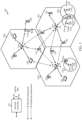
- FIG. 1 illustrates an example wireless network 100 in which aspects of the present disclosure may be performed.
- the wireless network 100 may include a network entity (e.g., a gNB 110) configured to perform operations 1000 of FIG. 10 to signal minimum scheduling delays to a UE 120 (configured to perform operations 1100 of FIG. 11
- a network entity e.g., a gNB 110
- FIG. 11 illustrates an example wireless network 100 in which aspects of the present disclosure may be performed.
- the wireless network 100 may include a network entity (e.g., a gNB 110) configured to perform operations 1000 of FIG. 10 to signal minimum scheduling delays to a UE 120 (configured to perform operations 1100 of FIG. 11
- a UE 120 may be configured for enhanced machine type communications (eMTC).
- the UE 120 may be considered a low cost device, low cost UE, eMTC device, and/or eMTC UE.
- the UE 120 can be configured to support higher bandwidth and/or data rates (e.g., higher than 1 MHz).
- the UE 120 may be configured with a plurality of narrowband regions (e.g., 24 resource blocks (RBs) or 96 RBs).
- the UE 120 may receive a resource allocation, from a gNB 110, allocating frequency hopped resources within a system bandwidth for the UE 120 to monitor and/or transmit on.
- the resource allocation can indicate non-contiguous narrowband frequency resources for uplink transmission in at least one subframe.
- the resource allocation may indicate frequency resources are not contained within a bandwidth capability of the UE to monitor for downlink transmission.
- the UE 120 may determine, based on the resource allocation, different narrowband than the resources indicated in the resource allocation from the gNB 110 for uplink transmission or for monitoring.
- the resource allocation indication (e.g., such as that included in the downlink control information (DCI)) may include a set of allocated subframes, frequency hopping related parameters, and an explicit resource allocation on the first subframe of the allocated subframes.
- the frequency hopped resource allocation on subsequent subframes are obtained by applying the frequency hopping procedure based on the frequency hopping related parameters (which may also be partly included in the DCI and configured partly through radio resource control (RRC) signaling) starting from the resources allocated on the first subframe of the allocated subframes.
- RRC radio resource control
- the wireless network 100 may include a number of gNBs 110 and other network entities.
- a gNB may be a station that communicates with UEs.
- Each gNB 110 may provide communication coverage for a particular geographic area.
- the term "cell” can refer to a coverage area of a Node B and/or a NB subsystem serving this coverage area, depending on the context in which the term is used.
- the term "cell” and NB, next generation NB (gNB), 5G NB, access point (AP), BS, NR BS, or transmission reception point (TRP) may be interchangeable.
- a cell may not necessarily be stationary, and the geographic area of the cell may move according to the location of a mobile gNB.
- the gNBs may be interconnected to one another and/or to one or more other gNBs or network nodes (not shown) in the wireless network 100 through various types of backhaul interfaces such as a direct physical connection, a virtual network, or the like using any suitable transport network.
- any number of wireless networks may be deployed in a given geographic area.
- Each wireless network may support a particular radio access technology (RAT) and may operate on one or more frequencies.
- a RAT may also be referred to as a radio technology, an air interface, etc.
- a frequency may also be referred to as a carrier, a frequency channel, a tone, a subband, a subcarrier, etc.
- Each frequency may support a single RAT in a given geographic area in order to avoid interference between wireless networks of different RATs.
- NR or 5G RAT networks may be deployed.
- a gNB may provide communication coverage for a macro cell, a pico cell, a femto cell, and/or other types of cell.
- a macro cell may cover a relatively large geographic area (e.g., several kilometers in radius) and may allow unrestricted access by UEs with service subscription.
- a pico cell may cover a relatively small geographic area and may allow unrestricted access by UEs with service subscription.
- a femto cell may cover a relatively small geographic area (e.g., a home) and may allow restricted access by UEs having association with the femto cell (e.g., UEs in a Closed Subscriber Group (CSG), UEs for users in the home, etc.).
- CSG Closed Subscriber Group
- a gNB for a macro cell may be referred to as a macro gNB.
- a gNB for a pico cell may be referred to as a pico gNB.
- a gNB for a femto cell may be referred to as a femto gNB or a home gNB.
- the gNBs 110a, 110b and 110c may be macro gNBs for the macro cells 102a, 102b and 102c, respectively.
- the gNB 110x may be a pico gNB for a pico cell 102x.
- the gNBs 110y and 110z may be femto gNB for the femto cells 102y and 102z, respectively.
- a gNB may support one or multiple (e.g., three) cells.
- the wireless network 100 may also include relay stations.
- a relay station is a station that receives a transmission of data and/or other information from an upstream station (e.g., a gNB or a UE) and sends a transmission of the data and/or other information to a downstream station (e.g., a UE or a gNB).
- a relay station may also be a UE that relays transmissions for other UEs.
- a relay station 110r may communicate with the gNB 110a and a UE 120r in order to facilitate communication between the gNB 110a and the UE 120r.
- a relay station may also be referred to as a relay gNB, a relay, etc.
- the wireless network 100 may be a heterogeneous network that includes gNBs of different types, e.g., macro gNB, pico gNB, femto gNB, relays, etc. These different types of gNBs may have different transmit power levels, different coverage areas, and different impact on interference in the wireless network 100.
- gNBs of different types, e.g., macro gNB, pico gNB, femto gNB, relays, etc.
- These different types of gNBs may have different transmit power levels, different coverage areas, and different impact on interference in the wireless network 100.
- a macro gNB may have a high transmit power level (e.g., 20 Watts)
- pico gNB, femto gNB, and relays may have a lower transmit power level (e.g., 1 Watt).
- the wireless network 100 may support synchronous or asynchronous operation.
- the gNBs may have similar frame timing, and transmissions from different gNBs may be approximately aligned in time.
- the gNBs may have different frame timing, and transmissions from different gNBs may not be aligned in time.
- the techniques described herein may be used for both synchronous and asynchronous operation.
- a network controller 130 may couple to a set of gNBs and provide coordination and control for these gNBs.
- the network controller 130 may communicate with the gNBs 110 via a backhaul.
- the gNBs 110 may also communicate with one another, for example, directly or indirectly via wireless or wireline backhaul.
- the UEs 120 may be dispersed throughout the wireless network 100, and each UE may be stationary or mobile.
- a UE may also be referred to as a mobile station, a terminal, an access terminal, a subscriber unit, a station, a Customer Premises Equipment (CPE), a cellular phone, a smart phone, a personal digital assistant (PDA), a wireless modem, a wireless communication device, a handheld device, a laptop computer, a cordless phone, a wireless local loop (WLL) station, a tablet, a camera, a gaming device, a netbook, a smartbook, an ultrabook, a medical device or medical equipment, a biometric sensor/device, a wearable device such as a smart watch, smart clothing, smart glasses, a smart wrist band, smart jewelry (e.g., a smart ring, a smart bracelet, etc.), an entertainment device (e.g., a music device, a video device, a
- CPE Customer Premises Equipment
- Some UEs may be considered evolved or machine-type communication (MTC) devices or evolved MTC (eMTC) devices.
- MTC and eMTC UEs include, for example, robots, drones, remote devices, sensors, meters, monitors, location tags, etc., that may communicate with a gNB, another device (e.g., remote device), or some other entity.
- a wireless node may provide, for example, connectivity for or to a network (e.g., a wide area network such as Internet or a cellular network) via a wired or wireless communication link.
- Some UEs may be considered Internet-of Things (IoT) devices or narrowband IoT (NB-IoT) devices.
- IoT Internet-of Things
- NB-IoT narrowband IoT
- a solid line with double arrows indicates desired transmissions between a UE and a serving gNB, which is a gNB designated to serve the UE on the downlink and/or uplink.
- a finely dashed line with double arrows indicates interfering transmissions between a UE and a gNB.
- Certain wireless networks utilize orthogonal frequency division multiplexing (OFDM) on the downlink and single-carrier frequency division multiplexing (SC-FDM) on the uplink.
- OFDM and SC-FDM partition the system bandwidth into multiple (K) orthogonal subcarriers, which are also commonly referred to as tones, bins, etc.
- K orthogonal subcarriers
- Each subcarrier may be modulated with data.
- modulation symbols are sent in the frequency domain with OFDM and in the time domain with SC-FDM.
- the spacing between adjacent subcarriers may be fixed, and the total number of subcarriers (K) may be dependent on the system bandwidth.
- the spacing of the subcarriers may be 15 kHz and the minimum resource allocation (e.g., an RB) may be 12 subcarriers (or 180 kHz). Consequently, the nominal FFT size may be equal to 128, 256, 512, 1024 or 2048 for system bandwidth of 1.25, 2.5, 5, 10 or 20 megahertz (MHz), respectively.
- the system bandwidth may also be partitioned into subbands. For example, a subband may cover 1.8 MHz (i.e., 6 resource blocks), and there may be 1, 2, 4, 8 or 16 subbands for system bandwidth of 1.25, 2.5, 5, 10 or 20 MHz, respectively.
- aspects of the examples described herein may be associated with LTE technologies, aspects of the present disclosure may be applicable with other wireless communications systems, such as NR.
- NR may utilize OFDM with a CP on the uplink and downlink and include support for half-duplex operation using TDD.
- a single component carrier bandwidth of 100 MHz may be supported.
- NR resource blocks may span 12 sub-carriers with a sub-carrier bandwidth of 75 kHz over a 0.1 ms duration.
- Each radio frame may consist of two half frames, each half frame consisting of 5 subframes, with a length of 10 ms. Consequently, each subframe may have a length of 1 ms.
- Each subframe may indicate a link direction (i.e., DL or UL) for data transmission and the link direction for each subframe may be dynamically switched.
- Each subframe may include DL/UL data as well as DL/UL control data.
- UL and DL subframes for NR may be as described in more detail below with respect to FIGs. 6 and 7 .
- Beamforming may be supported and beam direction may be dynamically configured.
- MIMO transmissions with precoding may also be supported.
- MIMO configurations in the DL may support up to 8 transmit antennas with multi-layer DL transmissions up to 8 streams and up to 2 streams per UE.
- Multi-layer transmissions with up to 2 streams per UE may be supported.
- Aggregation of multiple cells may be supported with up to 8 serving cells.
- the basic transmission time interval (TTI) or packet duration is the 1 subframe.
- TTI transmission time interval
- a subframe is still 1 ms, but the basic TTI is referred to as a slot.
- a subframe contains a variable number of slots (e.g., 1, 2, 4, 8, 16,... slots) depending on the tone-spacing (e.g., 15, 30, 60, 120, 240... kHz).
- a scheduling entity e.g., a gNB
- the scheduling entity may be responsible for scheduling, assigning, reconfiguring, and releasing resources for one or more subordinate entities. That is, for scheduled communication, subordinate entities utilize resources allocated by the scheduling entity.
- gNBs are not the only entities that may function as a scheduling entity. That is, in some examples, a UE may function as a scheduling entity, scheduling resources for one or more subordinate entities (e.g., one or more other UEs). In this example, the UE is functioning as a scheduling entity, and other UEs utilize resources scheduled by the UE for wireless communication.
- a UE may function as a scheduling entity in a peer-to-peer (P2P) network, and/or in a mesh network. In a mesh network example, UEs may optionally communicate directly with one another in addition to communicating with the scheduling entity.
- P2P peer-to-peer
- a scheduling entity and one or more subordinate entities may communicate utilizing the scheduled resources.
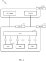
- FIG. 2 illustrates an example logical architecture of a distributed radio access network (RAN) 200, which may be implemented in the wireless communication system illustrated in FIG. 1 .
- a 5G access node 206 may include an access node controller (ANC) 202.
- the ANC 202 may be a central unit (CU) of the distributed RAN 200.
- the backhaul interface to the next generation core network (NG-CN) 204 may terminate at the ANC 202.
- the backhaul interface to neighboring next generation access nodes (NG-ANs) 210 may terminate at the ANC 202.
- the ANC 202 may include one or more TRPs 208 (which may also be referred to as BSs, NR BSs, gNBs, or some other term).
- the TRPs 208 may be a DU.
- the TRPs may be connected to one ANC (ANC 202) or more than one ANC (not illustrated).
- ANC 202 ANC 202
- RaaS radio as a service
- a TRP may include one or more antenna ports.
- the TRPs may be configured to individually (e.g., dynamic selection) or jointly (e.g., joint transmission) serve traffic to a UE.
- the logical architecture of the distributed RAN 200 may support fronthauling solutions across different deployment types.
- the logical architecture may be based on transmit network capabilities (e.g., bandwidth, latency, and/or jitter).
- the logical architecture may share features and/or components with LTE.
- the NG-AN 210 may support dual connectivity with NR.
- the NG-AN 210 may share a common fronthaul for LTE and NR.
- the logical architecture may enable cooperation between and among TRPs 208. For example, cooperation may be preset within a TRP and/or across TRPs via the ANC 202. An inter-TRP interface may be present.
- the logical architecture of the distributed RAN 200 may support a dynamic configuration of split logical functions.
- the Radio Resource Control (RRC) layer, Packet Data Convergence Protocol (PDCP) layer, Radio Link Control (RLC) layer, Medium Access Control (MAC) layer, and a Physical (PHY) layers may be adaptably placed at the DU or CU (e.g., TRP or ANC, respectively).
- RRC Radio Resource Control
- PDCP Packet Data Convergence Protocol
- RLC Radio Link Control
- MAC Medium Access Control
- PHY Physical
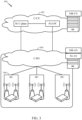
- FIG. 3 illustrates an example physical architecture of a distributed RAN 300, according to aspects of the present disclosure.
- a centralized core network unit (C-CU) 302 may host core network functions.
- the C-CU 302 may be centrally deployed.
- C-CU functionality may be offloaded (e.g., to advanced wireless services (AWS)), in an effort to handle peak capacity.
- AWS advanced wireless services
- a centralized RAN unit (C-RU) 304 may host one or more ANC functions.
- the C-RU 304 may host core network functions locally.
- the C-RU 304 may have distributed deployment.
- the C-RU 304 may be closer to the network edge.
- a DU 306 may host one or more TRPs (e.g., an edge node (EN), an edge unit (EU), a radio head (RH), a smart radio head (SRH), or the like).
- the DU may be located at edges of the network with radio frequency (RF) functionality.
- RF radio frequency
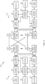
- FIG. 4 illustrates example components 400 of the gNB 110 and UE 120 illustrated in FIG. 1 , which may be used to implement aspects of the present disclosure for frequency hopping for large bandwidth allocations.
- antennas 452, Tx/Rx 222, processors 466, 458, 464, and/or controller/processor 480 of the UE 120 may be configured to perform operations 1100 of FIG. 11
- antennas 434, processors 460, 420, 438, and/or controller/processor 440 of the gNB 110 may be configured to perform operations 1100 of FIG. 10 .
- FIG. 4 shows a block diagram of a design of a gNB 110 and a UE 120, which may be one of the gNBs and one of the UEs in FIG. 1 .
- the gNB 110 may be the macro gNB 110c in FIG. 1
- the UE 120 may be the UE 120y.
- the gNB 110 may also be gNB of some other type.
- the gNB 110 may be equipped with antennas 434a through 434t, and the UE 120 may be equipped with antennas 452a through 452r.
- a transmit processor 420 may receive data from a data source 412 and control information from a controller/processor 440.
- the control information may be for the Physical Broadcast Channel (PBCH), Physical Control Format Indicator Channel (PCFICH), Physical Hybrid ARQ Indicator Channel (PHICH), Physical Downlink Control Channel (PDCCH), etc.
- the data may be for the Physical Downlink Shared Channel (PDSCH), etc.
- the processor 420 may process (e.g., encode and symbol map) the data and control information to obtain data symbols and control symbols, respectively.
- the processor 420 may also generate reference symbols, e.g., for the PSS, SSS, and cell-specific reference signal (CRS).
- CRS cell-specific reference signal
- a transmit (TX) multiple-input multiple-output (MIMO) processor 430 may perform spatial processing (e.g., precoding) on the data symbols, the control symbols, and/or the reference symbols, if applicable, and may provide output symbol streams to the modulators (MODs) 432a through 432t.
- Each modulator 432 may process a respective output symbol stream (e.g., for OFDM, etc.) to obtain an output sample stream.
- Each modulator 432 may further process (e.g., convert to analog, amplify, filter, and upconvert) the output sample stream to obtain a downlink signal.
- Downlink signals from modulators 432a through 432t may be transmitted via the antennas 434a through 434t, respectively.
- the antennas 452a through 452r may receive the downlink signals from the gNB 110 and may provide received signals to the demodulators (DEMODs) 454a through 454r, respectively.
- Each demodulator 454 may condition (e.g., filter, amplify, downconvert, and digitize) a respective received signal to obtain input samples.
- Each demodulator 454 may further process the input samples (e.g., for OFDM, etc.) to obtain received symbols.
- a MIMO detector 456 may obtain received symbols from all the demodulators 454a through 454r, perform MIMO detection on the received symbols if applicable, and provide detected symbols.
- a receive processor 458 may process (e.g., demodulate, deinterleave, and decode) the detected symbols, provide decoded data for the UE 120 to a data sink 460, and provide decoded control information to a controller/processor 480.
- a transmit processor 464 may receive and process data (e.g., for the Physical Uplink Shared Channel (PUSCH)) from a data source 462 and control information (e.g., for the Physical Uplink Control Channel (PUCCH) from the controller/processor 480.
- the transmit processor 464 may also generate reference symbols for a reference signal.
- the symbols from the transmit processor 464 may be precoded by a TX MIMO processor 466 if applicable, further processed by the demodulators 454a through 454r (e.g., for SC-FDM, etc.), and transmitted to the gNB 110.
- the uplink signals from the UE 120 may be received by the antennas 434, processed by the modulators 432, detected by a MIMO detector 436 if applicable, and further processed by a receive processor 438 to obtain decoded data and control information sent by the UE 120.
- the receive processor 438 may provide the decoded data to a data sink 439 and the decoded control information to the controller/processor 440.
- the controllers/processors 440 and 480 may direct the operation at the gNB 110 and the UE 120, respectively.
- the processor 440 and/or other processors and modules at the gNB 110 may perform or direct, e.g., the execution of various processes for the techniques described herein.
- the processor 480 and/or other processors and modules at the UE 120 may also perform or direct, e.g., the execution of the functional blocks illustrated in FIGs. 9 and 11 , and/or other processes for the techniques described herein.
- the processor 440 and/or other processors and modules at the gNB 110 may also perform or direct, e.g., the execution of the functional blocks illustrated in FIG. 10 , and/or other processes for the techniques described herein.
- the memories 442, 482 may store data and program codes for the gNB 110 and the UE 120, respectively.
- a scheduler 444 may schedule UEs for data transmission on the downlink and/or uplink.
- FIG. 5 illustrates a diagram 500 showing examples for implementing a communications protocol stack, according to aspects of the present disclosure.
- the illustrated communications protocol stacks may be implemented by devices operating in a in a 5G system (e.g., a system that supports uplink-based mobility).
- Diagram 500 illustrates a communications protocol stack including a Radio Resource Control (RRC) layer 510, a Packet Data Convergence Protocol (PDCP) layer 515, a Radio Link Control (RLC) layer 520, a Medium Access Control (MAC) layer 525, and a Physical (PHY) layer 530.
- RRC Radio Resource Control
- PDCP Packet Data Convergence Protocol
- RLC Radio Link Control
- MAC Medium Access Control
- PHY Physical
- the layers of a protocol stack may be implemented as separate modules of software, portions of a processor or ASIC, portions of non-collocated devices connected by a communications link, or various combinations thereof. Collocated and non-collocated implementations may be used, for example, in a protocol stack for a network access device (e.g., ANs, CUs, and/or DUs) or a UE.
- a network access device e.g., ANs, CUs, and/or DUs
- a first option 505-a shows a split implementation of a protocol stack, in which implementation of the protocol stack is split between a centralized network access device (e.g., an ANC 202 in FIG. 2 ) and distributed network access device (e.g., DU 208 in FIG. 2 ).
- a centralized network access device e.g., an ANC 202 in FIG. 2
- distributed network access device e.g., DU 208 in FIG. 2
- an RRC layer 510 and a PDCP layer 515 may be implemented by the central unit
- an RLC layer 520, a MAC layer 525, and a PHY layer 530 may be implemented by the DU.
- the CU and the DU may be collocated or non-collocated.
- the first option 505-a may be useful in a macro cell, micro cell, or pico cell deployment.
- a second option 505-b shows a unified implementation of a protocol stack, in which the protocol stack is implemented in a single network access device (e.g., access node (AN), new radio base station (NR BS), a new radio Node-B (NR NB), a network node (NN), or the like.).
- the RRC layer 510, the PDCP layer 515, the RLC layer 520, the MAC layer 525, and the PHY layer 530 may each be implemented by the AN.
- the second option 505-b may be useful in a femto cell deployment.
- a UE may implement an entire protocol stack (e.g., the RRC layer 510, the PDCP layer 515, the RLC layer 520, the MAC layer 525, and the PHY layer 530).
- an entire protocol stack e.g., the RRC layer 510, the PDCP layer 515, the RLC layer 520, the MAC layer 525, and the PHY layer 530.
- FIG. 6 is a diagram showing an example of a frame format 600 for NR.
- the transmission timeline for each of the downlink and uplink may be partitioned into units of radio frames.
- Each radio frame may have a predetermined duration (e.g., 10 ms) and may be partitioned into 10 subframes, each of 1 ms, with indices of 0 through 9.
- Each subframe may include a variable number of slots depending on the subcarrier spacing.
- Each slot may include a variable number of symbol periods (e.g., 7 or 14 symbols) depending on the subcarrier spacing.
- the symbol periods in each slot may be assigned indices.
- a mini-slot which may be referred to as a sub-slot structure, refers to a transmit time interval having a duration less than a slot (e.g., 2, 3, or 4 symbols).
- Each symbol in a slot may indicate a link direction (e.g., DL, UL, or flexible) for data transmission and the link direction for each subframe may be dynamically switched.
- the link directions may be based on the slot format.
- Each slot may include DL/LTL data as well as DL/UL control information.
- a synchronization signal (SS) block is transmitted.
- the SS block includes a PSS, a SSS, and a two symbol PBCH.
- the SS block can be transmitted in a fixed slot location, such as the symbols 0-3 as shown in FIG. 6 .
- the PSS and SSS may be used by UEs for cell search and acquisition.
- the PSS may provide half-frame timing
- the SS may provide the CP length and frame timing.
- the PSS and SSS may provide the cell identity.
- the PBCH carries some basic system information, such as downlink system bandwidth, timing information within radio frame, SS burst set periodicity, system frame number, etc.
- the SS blocks may be organized into SS bursts to support beam sweeping.
- Further system information such as, remaining minimum system information (RMSI), system information blocks (SIBs), other system information (OSI) can be transmitted on a physical downlink shared channel (PDSCH) in certain subframes.
- the SS block may be transmitted up to sixty-four times, for example, with up to sixty-four different beam directions for mmW.
- the up to sixty-four transmissions of the SS block are referred to as the SS burst set.
- two or more subordinate entities may communicate with each other using sidelink signals.
- Real-world applications of such sidelink communications may include public safety, proximity services, UE-to-network relaying, vehicle-to-vehicle (V2V) communications, Internet-of-Everything (IoE) communications, IoT communications, mission-critical mesh, and/or various other suitable applications.
- a sidelink signal may refer to a signal communicated from one subordinate entity (e.g., UE1) to another subordinate entity (e.g., UE2) without relaying that communication through the scheduling entity (e.g., UE or gNB), even though the scheduling entity may be utilized for scheduling and/or control purposes.
- the sidelink signals may be communicated using a licensed spectrum (unlike wireless local area networks, which typically use an unlicensed spectrum).
- a UE may operate in various radio resource configurations, including a configuration associated with transmitting pilots using a dedicated set of resources (e.g., a radio resource control (RRC) dedicated state, etc.) or a configuration associated with transmitting pilots using a common set of resources (e.g., an RRC common state, etc.).
- RRC radio resource control
- the UE may select a dedicated set of resources for transmitting a pilot signal to a network.
- the UE may select a common set of resources for transmitting a pilot signal to the network.
- a pilot signal transmitted by the UE may be received by one or more network access devices, such as an AN, or a DU, or portions thereof.
- Each receiving network access device may be configured to receive and measure pilot signals transmitted on the common set of resources, and also receive and measure pilot signals transmitted on dedicated sets of resources allocated to the UEs for which the network access device is a member of a monitoring set of network access devices for the UE.
- One or more of the receiving network access devices, or a CU to which receiving network access device(s) transmit the measurements of the pilot signals may use the measurements to identify serving cells for the UEs, or to initiate a change of serving cell for one or more of the UEs.
- New radio may refer to radios configured to operate according to a new air interface (e.g., other than Orthogonal Frequency Divisional Multiple Access (OFDMA)-based air interfaces) or fixed transport layer (e.g., other than Internet Protocol (IP)).
- NR may include Enhanced Mobile Broadband (eMBB) service targeting wide bandwidth (e.g. 80 MHz beyond), millimeter wave (mmW) targeting high carrier frequency (e.g. 60 GHz), massive MTC (mMTC) targeting non-backward compatible MTC techniques, and/or mission critical targeting ultra-reliable low latency communications (URLLC) service.
- the RAN may include a central unit (CU) and distributed units (DUs).
- a NR Node B e.g., 5G Node B
- TRPs transmission reception points
- BWP Bandwidth part
- cross-slot scheduling e.g., DCI in one slot schedules an event in another slot
- same-slot scheduling e.g., DCI in one slot schedules an event in the same slot
- BWP adaptation but may be cumbersome.
- cross-slot scheduling for power saving may not work if non-Type-D-quasi co location (QCL) aperiodic-channel state information (CSI) request is supported.
- QCL non-Type-D-quasi co location
- CSI non-Type-D-quasi co location
- FIG. 8 illustrates example downlink communications for BWP.
- slots 802 for BWPO may be narrow band (e.g., default BWP)
- slots 804 for BWP1 may be wide band and may employ same slot scheduling
- slots 806 for BWP2 may be wide band with cross-slot scheduling.
- Different BWPs may correspond to different power consumptions. Therefore, power may be saved by switching between BWPs, for example, from a BWP with a higher corresponding power consumption to a BWP with a lower power consumption.
- FIG. 9 illustrates an example downlink communications with multiple BWPs having DCI.
- the parameter k0 generally indicates a delay between DL grant and corresponding DL data (PDSCH) reception.
- the third row of table 1 may not be addressable.
- the DCI may indicate a BWP ID of 2 (e.g., indicating BWP2) and select the second row of another table (table 2), indicating a k0 of 1 to schedule data in slot 908.
- Certain aspects of the present disclosure provide enhancement to improve cross-slot scheduling configuration by implementing a minimum k0 threshold which may be dynamically updated or explicitly configured. For example, a UE may either invalidate DCI based on an indicated k0 or adjust the indicated k0, according to the minimum k0 threshold. Aspects described herein may also be beneficial to carrier aggregation (CA) power for cross-carrier scheduling. Similar techniques may also be applied for the parameter k2, used to indicate a delay between UL grant reception in DL and UL data (PUSCH) transmission.
- CA carrier aggregation
- FIG. 10 illustrates example operations 1000 for wireless communication, in accordance with certain aspects of the present disclosure.
- the operations 1000 may be performed, for example, by a base station, such as the base station 110.
- the operations 1000 begin, at block 1002, by determining a minimum threshold for a scheduling parameter that indicates a scheduling delay between an end of a physical downlink control channel (PDCCH) transmission and a beginning of a transmission scheduled by the PDCCH.
- the base station configures a user equipment (UE) with the minimum threshold.
- UE user equipment
- the minimum threshold may be specified in a standard.
- FIG. 11 illustrates example operations 1100 for wireless communication, in accordance with certain aspects of the present disclosure.
- the operations 1100 may be performed, for example, by a UE, such as the UE 120.
- the operations 1100 correspond to the operations 1000, but from the perspective of the UE 120.
- the operations 1100 begin, at block 1102, by receiving a physical downlink control channel (PDCCH) with downlink control information (DCI) signaling a scheduling parameter indicating a scheduling delay between an end of the PDCCH transmission and a beginning of a transmission scheduled by the PDCCH.
- PDCCH physical downlink control channel
- DCI downlink control information
- the UE determines a value of the scheduling parameter is below a minimum threshold.
- the UE taking at least one action in response to the determination.
- the minimum k0 threshold may be semi-statically signaled per scheduled CC or per UE via a DCI, medium access control (MAC)-control element (CE), or radio-resource control (RRC) configuration.
- the minimum k0 threshold may be explicitly RRC-configured per BWP. For example, entries in a PDSCH-symbolAllocation table with k0 less than a threshold, or a PUSCH-symbol allocation table with k2 less than a threshold, may be implicitly invalidated considered unusable. Error cases may occur if an invalidated entry is still indicated by scheduling, or if no entries in the table are valid.
- DCI may indicate a value for k0 that is smaller than the minimum threshold, which would be considered invalid by the UE. How the UE handles this condition may be left up to UE implementation. For example, as the UE is not expected to handle PDSCH scheduled with k0 smaller than the threshold, it may drop (e.g., ignore) this DCI.
- a threshold value may be added to an indication of k0 in the scheduling DCI.
- k0' may be calculated by the UE based on a sum of k0 and a k0 threshold indicated in the DCI. In this case, all entries in the PDSCH-symbolAllocation table may still be usable and the UE may not need to drop the DCI.
- a minimum of an indicated k0 and the k0 threshold may be used. For example, instead of dropping the DCI, the UE may set k0 to the threshold k0 (which serves as a minimum or "floor").
- the minimum threshold may be defined in specification.
- the minimum k0 threshold may be directly defined in the specification instead of by explicit configuration.
- the minimum threshold may be tied to connected mode discontinuous reception (C-DRX). For example, during the ON duration of the C-DRX mode, a larger minimum k0 threshold may be used and a smaller (or none) minimum k0 threshold when DRX inactivity timer is counting.
- C-DRX connected mode discontinuous reception
- the minimum k0 threshold may apply not only to PDSCH scheduling, but may be generalized to apply to other DL scheduling, including but not limited to CSI-RS transmitted on the DL after an A-CSI request is triggered by the network.
- CSI-RS is transmitted in the same slot as the A-CSI request DCI for non-Type-D-QCL. While the examples provided herein have described a minimum threshold for k0 and PDSCH scheduling to facilitate understanding, aspects of the present disclosure may be similarly applied to the UL counterpart of k0, the minimum k2 and PUSCH scheduling.
- TDRA time domain resource allocation
- the TDRA table configured for the target BWP is typically used. Because a UE does not know a-priori when it would receive a BWP-switching DCI, it may be difficult to guarantee that a schedulable k0 is always greater than zero, even if a minimum k0 is configured to be greater than zero for the current BWP. The following provide various approaches to work-around this problem.
- FDRA frequency domain RA
- minimum k0 is a function of all the entries in the TDRA table, but the UE does not know a-priori when and which BWP would be triggered to switch to (in case there are more than two BWPs configured).
- This minimum DL scheduling offset may accomplish the following:
- a UE-specific TDRA table may be used if available, so that a minimum scheduling offset may still apply.
- Minimum DL/UL scheduling offsets can be attributes of BWP configurations.
- the minimum DL/UL scheduling offsets in use can be a set of values associated with the BWP which is currently active.
- each minimum DL scheduling offset configured per DL BWP.
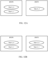
- both BWPO and BWP1 both have multiple minimum DL scheduling offsets (with the same values). The same use of multiple values can be used for minimum UL scheduling offsets and UL BWPs.
- minimum scheduling offsets corresponding to a large and small delay can be configured for BWP1.
- semi-static signaling e.g. via RRC signaling
- AC CE or DCI signaling may select which of the minimum scheduling offsets to use.
- the larger minimum scheduling offset can be selected to maximize power saving benefits.
- the minimum scheduling offset implicitly selected for use when the BWP becomes active can also be the value that was most recently selected for use when the BWP was last active. A default value may still need to be designated for the very first time the BWP becomes active after the BWP is (re)configured.
- the parameter sets configured per BWP need not be limited to minimum scheduling offsets only, but could be extended to include other parameters.
- the application time of the new value may account for the time taken for the reception and processing of the signaling.
- the current minimum scheduling offset defines the latest time that DCI processing has to finish. Therefore the application time of the new value may be such that it is not earlier than the current minimum scheduling offset from the slot the DCI indicating the change is received. Otherwise, a more stringent processing timeline may have to be imposed to DCI processing and may result in reduced power saving.
- the start time of the new minimum value (X_new) may be applied in the slot which is max(X, Z) number of slots after the DCI indicating the change is received.
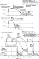
- FIG. 13 illustrates an example of operation with minimum DL scheduling offset for PDSCH.
- DCI with an indication of k0 which is smaller than the minimum DL scheduling offset may be considered invalid.
- TDRA table entries with k0 less than the minimum DL scheduling offset are essentially "dummy values.” Explicitly controlling the minimum scheduling offset may allow more flexibility in configuring the TDRA table. In some cases, the table may be configured with the same content for the table for different BWPs, while still having different minimum scheduling offset across BWPs.
- FIG. 14 illustrates an example of operation with minimum DL/LTL scheduling offset for A-CSI.
- the minimum DL scheduling offset may also serve as at least the lower bound for the triggering offset for aperiodic CSI-RS.
- the timing of CSI-RS may be a function of the configured CSI triggering offset (which is fixed to zero for non-QCL-Type-D in Rel-15), and the minimum DL scheduling offset. Two examples of such functions include:
- the minimum scheduling offset may be applied with scheduling across multiple BWPs.
- the illustrated example assumes a BWP switching latency of 1 slot, a single TDRA configured value (2) of k0 for BWPO and two TDRA configured values (0,2) of k0 for BWP1.
- the minimum DL scheduling offset may need to be satisfied (or a PDSCH scheduled by a DCI may be dropped as illustrated in the figure).
- search space configuration for cross-carrier scheduling may be based on the currently active BWP on the scheduled carrier. There may be a linkage rule for the search space defined for the scheduled carrier to that for the scheduling carrier. Similar to self-scheduling, the minimum k0 may be determined based on the TDRA tables across all schedulable BWP on the scheduled carrier, along with any additional conditions such as BWP transition latency.
- a UE may save more power by operating in lower power mode (e.g. at reduced clock / voltage for the baseband). The UE may even choose to suspend processing related to the SCell while it is not being scheduled, for example, with reduced CSI measurement and reporting, and/or SRS transmission.
- the scheduling carrier e.g., the primary cell or PCell
- the scheduled carrier e.g. SCell
- this can be achieved by careful configuration of minimum k0 across the BWP of the scheduled carrier.
- Explicit minimum scheduling offsets applied to cross-carrier scheduling may help solve the issue, while simplifying the configuration and operation.
- FIG. 16 illustrates how the minimum scheduling offset may be applied to Cross-Carrier Scheduling operation.
- the illustrated example assumes a BWP switching latency of 1 slot, a single TDRA configured value (3) of k0 for BWPO and two TDRA configured values (1,3) of k0 for BWP1.
- the minimum scheduling offset of the active BWP on the scheduled carrier guarantees certain scheduling delay.
- BWPO of CC1 can be the "power saving BWP" as it is configured with a large minimum DL scheduling offset. It can be used most of the time when traffic is sparse. When there is more traffic, BWP1 of CC1 can become the active BWP and a smaller minimum DL scheduling offset can be used for lower latency.
- minimum scheduling offsets may be used as UE feedback (e.g., implicitly indicating UE capability).
- UE feedback e.g., implicitly indicating UE capability.
- a non-zero minimum DL scheduling offset may need to be configured, but the amount of the offset may be dependent on UE capability (e.g. the buffering capacity it is designed to support).
- a UE may make sense for a UE to report a desired minimum scheduling offset effectively as an indication of UE capability. Extending this further, there may be a power saving benefit for having sufficiently large minimum scheduling offset for cross-carrier scheduling (regardless of same/different numerologies). The amount of scheduling delay needed to achieve power saving may be UE-implementation dependent.
- the UE capability framework described herein can be generalized to any cross-carrier scheduling configuration.
- a UE-based assistance framework may be used (to report a desired minimum scheduling offset) instead of UE capability framework.
- a UE may report preferred values of minimum scheduling offsets.
- the network may then decide, based on the UE-reported preferred values, how to configure the final minimum scheduling offsets.
- a minimum UL scheduling offsets described herein could be applied to a variety of different uplink transmissions.
- a sounding reference signal (SRS) is one example of such a transmission.
- a minimum UL scheduling offset could be applied to an aperiodic SRS (A-SRS) transmitted on the uplink after an (A-SRS) request is triggered (e.g., via DCI conveyed in a PDCCH).
- A-SRS aperiodic SRS
- an A-SRS configuration may be signaled via RRC signaling and triggered via DCI.
- the time granularity of the scheduling parameter in the DCI and/or the minimum threshold may vary.
- the granularity in either symbol resolution or slot resolution may be used.
- symbol level resolution may be derived from a scheduling parameter (e.g., indicated from a TDRA table).
- the granularity may be quantized to a slot resolution.
- the granularity may be based on the numerology of the transmission scheduled by the PDCCH, in case it is different from the numerology of the PDCCH. In other cases, the granularity could be based on the PDCCH. In some other cases, the granularity could be based on the numerology of the currently active BWP, or a reference numerology.
- the term numerology generally refers to waveform parameters, such as cyclic prefix length and subcarrier spacing (SCS). In general, the duration of an OFDM symbol is inversely proportional to subcarrier spacing.
- the methods disclosed herein comprise one or more steps or actions for achieving the described method.
- the method steps and/or actions may be interchanged with one another without departing from the scope of the claims.
- the order and/or use of specific steps and/or actions may be modified without departing from the scope of the claims.
- a phrase referring to "at least one of" a list of items refers to any combination of those items, including single members.
- "at least one of: a, b, or c” is intended to cover a, b, c, a-b, a-c, b-c, and a-b-c, as well as any combination with multiples of the same element (e.g., a-a, a-a-a, a-a-b, a-a-c, a-b-b, a-c-c, b-b, b-b-b, b-b-c, c-c, and c-c-c or any other ordering of a, b, and c).
- determining encompasses a wide variety of actions. For example, “determining” may include calculating, computing, processing, deriving, investigating, looking up (e.g., looking up in a table, a database or another data structure), ascertaining and the like. Also, “determining” may include receiving (e.g., receiving information), accessing (e.g., accessing data in a memory) and the like. Also, “determining” may include resolving, selecting, choosing, establishing and the like.
- the various operations of methods described above may be performed by any suitable means capable of performing the corresponding functions.
- the means may include various hardware and/or software component(s) and/or module(s), including, but not limited to a circuit, an application specific integrated circuit (ASIC), or processor.
- ASIC application specific integrated circuit
- DSP digital signal processor
- ASIC application specific integrated circuit
- FPGA field programmable gate array
- PLD programmable logic device
- a general-purpose processor may be a microprocessor, but in the alternative, the processor may be any commercially available processor, controller, microcontroller, or state machine.
- a processor may also be implemented as a combination of computing devices, e.g., a combination of a DSP and a microprocessor, a plurality of microprocessors, one or more microprocessors in conjunction with a DSP core, or any other such configuration.
- an example hardware configuration may comprise a processing system in a wireless node.
- the processing system may be implemented with a bus architecture.
- the bus may include any number of interconnecting buses and bridges depending on the specific application of the processing system and the overall design constraints.
- the bus may link together various circuits including a processor, machine-readable media, and a bus interface.
- the bus interface may be used to connect a network adapter, among other things, to the processing system via the bus.
- the network adapter may be used to implement the signal processing functions of the PHY layer.
- a user interface e.g., keypad, display, mouse, joystick, etc.
- the bus may also link various other circuits such as timing sources, peripherals, voltage regulators, power management circuits, and the like, which are well known in the art, and therefore, will not be described any further.
- the processor may be implemented with one or more general-purpose and/or special-purpose processors. Examples include microprocessors, microcontrollers, DSP processors, and other circuitry that can execute software. Those skilled in the art will recognize how best to implement the described functionality for the processing system depending on the particular application and the overall design constraints imposed on the overall system.
- the functions may be stored or transmitted over as one or more instructions or code on a computer-readable medium.
- Software shall be construed broadly to mean instructions, data, or any combination thereof, whether referred to as software, firmware, middleware, microcode, hardware description language, or otherwise.
- Computer-readable media include both computer storage media and communication media including any medium that facilitates transfer of a computer program from one place to another.
- the processor may be responsible for managing the bus and general processing, including the execution of software modules stored on the machine-readable storage media.
- a computer-readable storage medium may be coupled to a processor such that the processor can read information from, and write information to, the storage medium. In the alternative, the storage medium may be integral to the processor.
- the machine-readable media may include a transmission line, a carrier wave modulated by data, and/or a computer readable storage medium with instructions stored thereon separate from the wireless node, all of which may be accessed by the processor through the bus interface.
- the machine-readable media, or any portion thereof may be integrated into the processor, such as the case may be with cache and/or general register files.
- machine-readable storage media may include, by way of example, RAM (Random Access Memory), flash memory, ROM (Read Only Memory), PROM (Programmable Read-Only Memory), EPROM (Erasable Programmable Read-Only Memory), EEPROM (Electrically Erasable Programmable Read-Only Memory), registers, magnetic disks, optical disks, hard drives, or any other suitable storage medium, or any combination thereof.
- RAM Random Access Memory
- ROM Read Only Memory
- PROM PROM
- EPROM Erasable Programmable Read-Only Memory
- EEPROM Electrical Erasable Programmable Read-Only Memory
- registers magnetic disks, optical disks, hard drives, or any other suitable storage medium, or any combination thereof.
- the machine-readable media may be embodied in a computer-program product.
- a software module may comprise a single instruction, or many instructions, and may be distributed over several different code segments, among different programs, and across multiple storage media.
- the computer-readable media may comprise a number of software modules.
- the software modules include instructions that, when executed by an apparatus such as a processor, cause the processing system to perform various functions.
- the software modules may include a transmission module and a receiving module. Each software module may reside in a single storage device or be distributed across multiple storage devices.
- a software module may be loaded into RAM from a hard drive when a triggering event occurs.
- the processor may load some of the instructions into cache to increase access speed.
- One or more cache lines may then be loaded into a general register file for execution by the processor.
- any connection is properly termed a computer-readable medium.
- the software is transmitted from a website, server, or other remote source using a coaxial cable, fiber optic cable, twisted pair, digital subscriber line (DSL), or wireless technologies such as infrared (IR), radio, and microwave
- the coaxial cable, fiber optic cable, twisted pair, DSL, or wireless technologies such as infrared, radio, and microwave are included in the definition of medium.
- Disk and disc include compact disc (CD), laser disc, optical disc, digital versatile disc (DVD), floppy disk, and Blu-ray ® disc where disks usually reproduce data magnetically, while discs reproduce data optically with lasers.
- computer-readable media may comprise non-transitory computer-readable media (e.g., tangible media).
- computer-readable media may comprise transitory computer- readable media (e.g., a signal). Combinations of the above should also be included within the scope of computer-readable media.
- certain aspects may comprise a computer program product for performing the operations presented herein.
- a computer program product may comprise a computer-readable medium having instructions stored (and/or encoded) thereon, the instructions being executable by one or more processors to perform the operations described herein.
- modules and/or other appropriate means for performing the methods and techniques described herein can be downloaded and/or otherwise obtained by a user terminal and/or base station as applicable.
- a user terminal and/or base station can be coupled to a server to facilitate the transfer of means for performing the methods described herein.
- various methods described herein can be provided via storage means (e.g., RAM, ROM, a physical storage medium such as a compact disc (CD) or floppy disk, etc.), such that a user terminal and/or base station can obtain the various methods upon coupling or providing the storage means to the device.
- storage means e.g., RAM, ROM, a physical storage medium such as a compact disc (CD) or floppy disk, etc.
- CD compact disc
- floppy disk etc.
- any other suitable technique for providing the methods and techniques described herein to a device can be utilized.
Landscapes
- Engineering & Computer Science (AREA)
- Signal Processing (AREA)
- Computer Networks & Wireless Communication (AREA)
- Quality & Reliability (AREA)
- Power Engineering (AREA)
- Mobile Radio Communication Systems (AREA)
- Management, Administration, Business Operations System, And Electronic Commerce (AREA)
Claims (15)
- Procédé de communication sans fil par un équipement utilisateur, UE, comprenant :la réception (1102) d'une transmission sur canal physique de commande de liaison descendante, PDCCH, comportant des informations de commande de liaison descendante, DCI, signalant un paramètre d'ordonnancement indiquant un retard d'ordonnancement entre une fin de la transmission PDCCH et un début d'une transmission ordonnancée par le PDCCH ;la détermination (1104) qu'une valeur du paramètre d'ordonnancement est inférieure ou non à un seuil minimum ;le traitement des DCI comme étant non valides si la valeur du paramètre d'ordonnancement est inférieure au seuil minimum ; etla réception de la transmission ordonnancée par le PDCCH si la valeur du paramètre d'ordonnancement n'est pas inférieure au seuil minimum, dans lequel la transmission ordonnancée comprend au moins un signal de référence d'informations d'état de canal, CSI-RS, transmis sur la liaison descendante après le déclenchement d'une demande CSI apériodique (A-CSI).
- Procédé selon la revendication 1, dans lequel une valeur du seuil minimum est signalée pour chaque porteuse constituante programmée, CC ou pour chaque UE par au moins :
des DCI, un élément de commande, CE, de commande d'accès au support, MAC, ou une configuration de commande de ressources radio, RRC. - Procédé selon la revendication 1, dans lequel une ou plusieurs valeurs du seuil minimum sont configurées par partie de largeur de bande, BWP ; et de préférencedans lequel la valeur du seuil minimum utilisée pour la détermination est basée sur une BWP actuellement active ; et idéalementle procédé comprend :
la détermination d'entrées dans au moins une table d'allocation de symboles de canal partagé de liaison descendante physique, PDSCH, ou une table d'allocation de symboles de canal partagé de liaison montante physique, PUSCH, avec un paramètre d'ordonnancement correspondant inférieur au seuil minimum comme étant au moins invalides ou inutilisables en fonction de la détermination que la valeur du paramètre d'ordonnancement est inférieure au seuil minimum. - Procédé selon la revendication 1, comprenant en outre la réception d'une signalisation indiquant le seuil minimum.
- Procédé selon la revendication 4, dans lequel la signalisation comporte une sélection parmi un ensemble de valeurs de la valeur de seuil minimum ; et de préférence dans lequel :l'ensemble de valeurs est signalé par une signalisation de commande de ressources radio, RRC ; etune valeur de l'ensemble de valeurs est sélectionnée par l'intermédiaire d'au moins : un élément de commande d'accès au support, MAC, une signalisation CE ou des DCI ; et/oule procédé comprend en outre la sélection d'une des valeurs en fonction d'une charge de trafic.
- Procédé selon la revendication 1, dans lequel une valeur du seuil minimum est signalés pour chaque BWP.
- Procédé selon la revendication 1, dans lequel la détermination que la valeur du paramètre d'ordonnancement est inférieure ou non à un seuil minimum est réalisée dans une résolution de symbole multiplexée par répartition orthogonale de la fréquence, OFDM, ou une résolution de tranche, sur la base d'une numérologie du PDCCH, d'une numérologie de la transmission ordonnancée par le PDCCH, d'une numérologie de la BWP actuellement active, ou d'une numérologie de référence.
- Procédé de communications sans fil par une entité de réseau, comprenant :la détermination (1002) d'un seuil minimum pour un paramètre d'ordonnancement qui indique un retard d'ordonnancement entre une fin d'une transmission sur canal physique de commande de liaison descendante, PDCCH, et un début d'une transmission ordonnancée par le PDCCH ; etla configuration (1004) d'un équipement utilisateur, UE, avec le seuil minium dans lequel la transmission ordonnancée comprend au moins un signal de référence d'informations d'état de canal, CSI-RS, transmis sur la liaison descendante après le déclenchement d'une demande CSI apériodique, A-CSI.
- Procédé selon la revendication 8, dans lequel une ou plusieurs valeurs du seuil minimum sont configurées pour chaque partie de largeur de bande, BWP
- Procédé selon la revendication 8, comprenant en outre la fourniture d'une signalisation indiquant le seuil minimum ; et de préférencedans lequel la signalisation indique une sélection de la valeur seuil minimum parmi un ensemble de valeurs ; et de préférence.dans lequel:l'ensemble de valeurs est indiqué par une signalisation de commande de ressources radio, RRC ; etle procédé comprend en outre la fourniture d'une signalisation sélectionnant une valeur de l'ensemble de valeurs par au moins : un élément de commande, CE, de commande d'accès au support, MAC, ou une signalisation de DCI ; et/oule procédé comprend en outre la sélection d'une des valeurs en fonction d'une charge de trafic.
- Procédé selon la revendication 8, dans lequel une valeur du seuil minimum est signalée pour chaque BWP ; et/ou
dans lequel la détermination du seuil minimum est réalisée dans un résolution de symbole multiplexée par répartition orthogonale de la fréquence, OFDM, ou une résolution de tranche, en fonction d'une numérologie du PDCCH ou de la numérologie de la transmission ordonnancée par le PDCCH. - Appareil de communication sans fil par un équipement utilisateur, UE, comprenant :un moyen (464) de réception d'une transmission sur un canal physique de commande de liaison descendante, PDCCH, comportant des informations de commande de liaison descendante (DCI) signalant un paramètre d'ordonnancement indiquant un retard d'ordonnancement entre une fin de la transmission PDCCH et un début d'une transmission ordonnancée par le PDCCH ;un moyen de détermination qu'une valeur du paramètre d'ordonnancement est inférieure ou non à un seuil minimum ;un moyen de traitement des DCI comme étant invalides si la valeur du paramètre d'ordonnancement est inférieure au seuil minimum ; etun moyen de réception de la transmission ordonnancée par le PDCCH si la valeur du paramètre d'ordonnancement n'est pas inférieure au seuil minimum, dans lequel la transmission ordonnancée comprend au moins un signal de référence d'informations d'état de canal, CSI-RS, transmis sur la liaison descendante après le déclenchement d'une demande CSI apériodique (A-CSI).
- Appareil selon la revendication 12, comprenant en outre un moyen de réalisation du procédé selon l'une quelconque des revendications 2 à 7.
- Appareil de communication sans fil par une entité de réseau, comprenant :un moyen (440) de détermination d'un seuil minimum pour un paramètre d'ordonnancement qui indique un retard d'ordonnancement entre une fin d'une transmission sur canal physique de commande de liaison descendante, PDCCH, et un début d'une transmission ordonnancée par le PDCCH ; etun moyen (420) de configuration d'un équipement utilisateur, UE, avec le seuil minimum dans lequel la transmission ordonnancée comprend au moins un signal de référence d'informations d'état de canal, CSI-RS, transmis sur la liaison descendante après le déclenchement d'une demande apériodique CSI, A-CSI.
- Appareil selon la revendication 14, comprenant en outre un moyen de réalisation du procédé selon l'une quelconque des revendications 9 à 11.
Priority Applications (1)
| Application Number | Priority Date | Filing Date | Title |
|---|---|---|---|
| EP23209685.9A EP4333550B1 (fr) | 2018-09-28 | 2019-09-27 | Signalisation d'un retard minimal d'ordonnancement |
Applications Claiming Priority (6)
| Application Number | Priority Date | Filing Date | Title |
|---|---|---|---|
| US201862739084P | 2018-09-28 | 2018-09-28 | |
| US201962791445P | 2019-01-11 | 2019-01-11 | |
| US201962828220P | 2019-04-02 | 2019-04-02 | |
| US201962847045P | 2019-05-13 | 2019-05-13 | |
| US16/584,833 US11382118B2 (en) | 2018-09-28 | 2019-09-26 | Minimum scheduling delay signaling |
| PCT/US2019/053374 WO2020069264A1 (fr) | 2018-09-28 | 2019-09-27 | Signalisation d'un retard minimal d'ordonnancement |
Related Child Applications (1)
| Application Number | Title | Priority Date | Filing Date |
|---|---|---|---|
| EP23209685.9A Division EP4333550B1 (fr) | 2018-09-28 | 2019-09-27 | Signalisation d'un retard minimal d'ordonnancement |
Publications (2)
| Publication Number | Publication Date |
|---|---|
| EP3858037A1 EP3858037A1 (fr) | 2021-08-04 |
| EP3858037B1 true EP3858037B1 (fr) | 2023-12-06 |
Family
ID=69945282
Family Applications (2)
| Application Number | Title | Priority Date | Filing Date |
|---|---|---|---|
| EP23209685.9A Active EP4333550B1 (fr) | 2018-09-28 | 2019-09-27 | Signalisation d'un retard minimal d'ordonnancement |
| EP19789817.4A Active EP3858037B1 (fr) | 2018-09-28 | 2019-09-27 | Signalisation d'un retard minimal d'ordonnancement |
Family Applications Before (1)
| Application Number | Title | Priority Date | Filing Date |
|---|---|---|---|
| EP23209685.9A Active EP4333550B1 (fr) | 2018-09-28 | 2019-09-27 | Signalisation d'un retard minimal d'ordonnancement |
Country Status (4)
| Country | Link |
|---|---|
| US (3) | US11382118B2 (fr) |
| EP (2) | EP4333550B1 (fr) |
| CN (1) | CN112740798B (fr) |
| WO (1) | WO2020069264A1 (fr) |
Cited By (1)
| Publication number | Priority date | Publication date | Assignee | Title |
|---|---|---|---|---|
| US20230371040A1 (en) * | 2020-10-14 | 2023-11-16 | Zte Corporation | Information determination method and apparatus, device, and storage medium |
Families Citing this family (32)
| Publication number | Priority date | Publication date | Assignee | Title |
|---|---|---|---|---|
| CN110719631B (zh) * | 2018-07-12 | 2021-12-28 | 维沃移动通信有限公司 | 调度参数的确定方法、配置方法、终端和网络侧设备 |
| US12262320B2 (en) | 2018-09-24 | 2025-03-25 | Telefonaktiebolaget Lm Ericsson (Publ) | Control of power saving using layer-1 signaling |
| US12101766B2 (en) | 2018-09-24 | 2024-09-24 | Telefonaktiebolaget Lm Ericsson (Publ) | Control of DRX using layer-1 signaling |
| JP7230187B2 (ja) * | 2018-09-28 | 2023-02-28 | テレフオンアクチーボラゲット エルエム エリクソン(パブル) | 異なるスケジューリング遅延の仮説間での移行 |
| US11382118B2 (en) | 2018-09-28 | 2022-07-05 | Qualcomm Incorporated | Minimum scheduling delay signaling |
| US11375518B2 (en) * | 2019-01-23 | 2022-06-28 | Samsung Electronics Co., Ltd. | Method and apparatus for managing PDCCH processing timelines |
| US11483767B2 (en) * | 2019-02-15 | 2022-10-25 | Mediatek Inc. | Cross-slot scheduling for power saving in mobile communications |
| KR102401124B1 (ko) * | 2019-02-27 | 2022-05-23 | 엘지전자 주식회사 | 사이드링크 통신을 수행하는 장치의 장치 능력 보고 |
| US11166269B2 (en) * | 2019-03-28 | 2021-11-02 | Ofinno, Llc | Interaction between power saving adaptation and bandwidth part adaptation |
| CN111757473B (zh) * | 2019-03-28 | 2023-05-09 | 中国移动通信有限公司研究院 | 一种基于带宽部分的终端节能方法 |
| CN111757435B (zh) * | 2019-03-29 | 2025-01-14 | 华为技术有限公司 | 一种无线通信的方法、终端设备及网络设备 |
| EP3895489B1 (fr) | 2019-04-02 | 2024-09-11 | ZTE Corporation | Systèmes et procédés de gestion des informations de décalage de créneau |
| ES3048082T3 (en) * | 2019-05-03 | 2025-12-09 | Nokia Technologies Oy | Dynamic scheduling offset adaptation in ue power saving |
| CN112399569A (zh) * | 2019-08-14 | 2021-02-23 | 华为技术有限公司 | 一种通信方法及通信装置 |
| CN110351871B (zh) * | 2019-08-16 | 2021-10-29 | 展讯通信(上海)有限公司 | 用于指示最小调度时延的方法、装置及存储介质 |
| US10972354B1 (en) * | 2019-09-16 | 2021-04-06 | Sprint Spectrum L.P. | Wireless communication between a wide bandwidth network node and a narrow bandwidth wireless device |
| EP4021128B1 (fr) * | 2019-09-26 | 2025-05-28 | Samsung Electronics Co., Ltd. | Procédé et dispositif de planification inter-créneau dans un système de communication sans fil |
| CN119676834A (zh) * | 2019-09-30 | 2025-03-21 | 华为技术有限公司 | 一种通信方法及装置 |
| EP4140182A4 (fr) | 2020-04-24 | 2024-01-17 | Lenovo (Beijing) Limited | Procédés et appareil pour fdm dynamique entre une liaison parent et une liaison enfant dans un réseau iab |
| WO2021109437A1 (fr) * | 2020-04-30 | 2021-06-10 | Zte Corporation | Architecture de coordination de réponses de signalisation |
| CN113677015A (zh) * | 2020-05-15 | 2021-11-19 | 华为技术有限公司 | 一种数据处理方法及相关设备 |
| WO2021229038A1 (fr) * | 2020-05-15 | 2021-11-18 | Telefonaktiebolaget Lm Ericsson (Publ) | Signalisation de capacité dans un réseau de communication sans fil |
| US20230199782A1 (en) * | 2020-05-15 | 2023-06-22 | Qualcomm Incorporated | Secondary cell dormancy indication for scheduling multiple component carriers |
| US11943730B2 (en) | 2020-07-13 | 2024-03-26 | Qualcomm Incorporated | Search space specific delay between a downlink control channel and corresponding downlink/uplink data |
| US11876742B2 (en) * | 2020-07-27 | 2024-01-16 | Samsung Electronics Co., Ltd | Method and apparatus for enhancing SRS flexibility, coverage, and capacity in a communication system |
| CN114071667B (zh) * | 2020-08-07 | 2025-09-05 | 华为技术有限公司 | 通信的方法、通信装置及系统 |
| US12069626B2 (en) | 2020-10-07 | 2024-08-20 | Qualcomm Incorporated | Adaptive processing modes |
| CN120979933A (zh) * | 2020-10-12 | 2025-11-18 | 苹果公司 | 蜂窝通信系统中的非周期性探测参考信号偏移的动态配置 |
| CN112514317B (zh) * | 2020-11-06 | 2023-07-07 | 北京小米移动软件有限公司 | 一种通信方法、通信装置及存储介质 |
| WO2022151234A1 (fr) * | 2021-01-14 | 2022-07-21 | Apple Inc. | Systèmes et procédés de signalisation multi-pxsch à hautes fréquences |
| WO2022151301A1 (fr) * | 2021-01-15 | 2022-07-21 | Zte Corporation | Système et procédés d'optimisation de synchronisation de transmission |
| WO2023102841A1 (fr) * | 2021-12-09 | 2023-06-15 | Nec Corporation | Procédé, dispositif et support de stockage informatique de communication |
Family Cites Families (14)
| Publication number | Priority date | Publication date | Assignee | Title |
|---|---|---|---|---|
| US10075969B2 (en) * | 2011-04-25 | 2018-09-11 | Texas Instruments Incorporated | Medium access control schedulers for wireless communication |
| US9300431B2 (en) * | 2012-06-04 | 2016-03-29 | Alcatel Lucent | Apparatus, method and computer readable medium for payload segmentation of wireless packet data transmissions |
| US10356716B2 (en) * | 2014-07-17 | 2019-07-16 | Telefonaktiebolaget Lm Ericsson (Publ) | Method and network element for scheduling a communication device |
| KR102349361B1 (ko) | 2015-05-29 | 2022-01-10 | 애플 인크. | 5g 및 lte 시스템 및 장치에서의 단절없는 이동 |
| CN109314982B (zh) | 2016-06-10 | 2022-03-01 | Lg 电子株式会社 | 无线通信系统中减少时延的信号发送和接收方法及其装置 |
| US10470200B2 (en) | 2016-06-16 | 2019-11-05 | Qualcomm Incorporated | Low complexity higher order MIMO |
| CN108076455A (zh) | 2016-11-14 | 2018-05-25 | 北京信威通信技术股份有限公司 | 一种配置最小处理时延的方法及装置 |
| DE112018001537T5 (de) | 2017-03-22 | 2019-12-05 | Intel IP Corporation | Zeitbestimmungstechniken für 5g-Funkzugangsnetzwerk-Zellen |
| WO2019027209A1 (fr) * | 2017-07-31 | 2019-02-07 | 엘지전자 주식회사 | Procédé d'émission et de réception de signal sur la base de lte et de nr dans un système de communication sans fil et dispositif correspondant |
| EP3509373B1 (fr) * | 2018-01-09 | 2023-03-08 | Comcast Cable Communications LLC | Sélection de faisceau dans une retransmission de demande de reprise après défaillance de faisceau |
| US10993254B2 (en) | 2018-02-16 | 2021-04-27 | Qualcomm Incorporated | Downlink control information signaling schemes for bandwidth part switching |
| CN110691416B (zh) * | 2018-07-05 | 2023-06-09 | 华为技术有限公司 | 一种资源调度的方法和装置 |
| TWI750499B (zh) * | 2018-08-21 | 2021-12-21 | 美商Idac控股公司 | 無線傳輸/接收單元(wtru)功率控制方法及裝置 |
| US11382118B2 (en) | 2018-09-28 | 2022-07-05 | Qualcomm Incorporated | Minimum scheduling delay signaling |
-
2019
- 2019-09-26 US US16/584,833 patent/US11382118B2/en active Active
- 2019-09-27 EP EP23209685.9A patent/EP4333550B1/fr active Active
- 2019-09-27 EP EP19789817.4A patent/EP3858037B1/fr active Active
- 2019-09-27 WO PCT/US2019/053374 patent/WO2020069264A1/fr not_active Ceased
- 2019-09-27 CN CN201980062481.XA patent/CN112740798B/zh active Active
-
2020
- 2020-02-26 US US16/802,487 patent/US10887906B2/en active Active
-
2022
- 2022-06-22 US US17/846,370 patent/US11950229B2/en active Active
Cited By (2)
| Publication number | Priority date | Publication date | Assignee | Title |
|---|---|---|---|---|
| US20230371040A1 (en) * | 2020-10-14 | 2023-11-16 | Zte Corporation | Information determination method and apparatus, device, and storage medium |
| US12526816B2 (en) * | 2020-10-14 | 2026-01-13 | Zte Corporation | Information determination method and apparatus, device, and storage medium |
Also Published As
| Publication number | Publication date |
|---|---|
| US20200196337A1 (en) | 2020-06-18 |
| US10887906B2 (en) | 2021-01-05 |
| EP3858037A1 (fr) | 2021-08-04 |
| EP4333550C0 (fr) | 2025-09-03 |
| CN112740798B (zh) | 2024-12-27 |
| US20200107345A1 (en) | 2020-04-02 |
| CN112740798A (zh) | 2021-04-30 |
| US11382118B2 (en) | 2022-07-05 |
| US20220330302A1 (en) | 2022-10-13 |
| US11950229B2 (en) | 2024-04-02 |
| EP4333550B1 (fr) | 2025-09-03 |
| EP4333550A2 (fr) | 2024-03-06 |
| EP4333550A3 (fr) | 2024-03-20 |
| WO2020069264A1 (fr) | 2020-04-02 |
Similar Documents
| Publication | Publication Date | Title |
|---|---|---|
| US11950229B2 (en) | Minimum scheduling delay signaling | |
| KR102778455B1 (ko) | 빔 스위치 시간 능력의 피드백 | |
| US11101950B2 (en) | Demodulation reference signal (DMRS) bundling in slot aggregation and slot format considerations for new radio | |
| US11310838B2 (en) | Uplink and downlink preemption indications | |
| EP3769572B1 (fr) | Considérations sur la gestion de partie de bande passante (bwp) pour une communication à faible latence ultra-fiable (urllc) | |
| US11431463B2 (en) | Minimum scheduling offset | |
| EP3824582B1 (fr) | Mesure de porteuse transversale avec des signaux de référence d'informations d'état de canal apériodique (csi-rs) | |
| AU2019211145B2 (en) | Uplink power control configuration | |
| EP3791530B1 (fr) | Calcul d'informations d'état de canal apériodiques pour programmation inter-porteuse | |
| US11757599B2 (en) | Limits on quantity of downlink control information (DCI) processed | |
| EP3577937B1 (fr) | Couplage de structure de symbole de référence (rs) d'informations d'état de canal (csi) apériodiques (csi-rs) avec un contenu de rétroaction et une synchronisation de rapport | |
| EP3824585B1 (fr) | Planification multiporteuse et activation d'espace de recherche | |
| WO2020020075A1 (fr) | Collision entre des signaux de référence de sondage (srs) et d'autres canaux de liaison montante | |
| KR20230129593A (ko) | 그룹 공통 pdcch 내의 슬롯 포맷 표시자(sfi) 및 슬롯 어그리게이션 레벨 표시 및 sfi 충돌 핸들링 | |
| WO2021091876A1 (fr) | Mise à jour simultanée de comportement d'économie d'énergie sur de multiples ensembles de ressources de fréquence | |
| EP3704904B1 (fr) | Compte-rendu de marge de puissance d'intervalle de temps de transmission (tti) court | |
| US11330446B2 (en) | Dynamically enabling dual default beams |
Legal Events
| Date | Code | Title | Description |
|---|---|---|---|
| STAA | Information on the status of an ep patent application or granted ep patent |
Free format text: STATUS: UNKNOWN |
|
| STAA | Information on the status of an ep patent application or granted ep patent |
Free format text: STATUS: THE INTERNATIONAL PUBLICATION HAS BEEN MADE |
|
| PUAI | Public reference made under article 153(3) epc to a published international application that has entered the european phase |
Free format text: ORIGINAL CODE: 0009012 |
|
| STAA | Information on the status of an ep patent application or granted ep patent |
Free format text: STATUS: REQUEST FOR EXAMINATION WAS MADE |
|
| 17P | Request for examination filed |
Effective date: 20210329 |
|
| AK | Designated contracting states |
Kind code of ref document: A1 Designated state(s): AL AT BE BG CH CY CZ DE DK EE ES FI FR GB GR HR HU IE IS IT LI LT LU LV MC MK MT NL NO PL PT RO RS SE SI SK SM TR |
|
| DAV | Request for validation of the european patent (deleted) | ||
| DAX | Request for extension of the european patent (deleted) | ||
| REG | Reference to a national code |
Ref country code: DE Ref legal event code: R079 Free format text: PREVIOUS MAIN CLASS: H04W0072040000 Ipc: H04L0005000000 Ref document number: 602019042883 Country of ref document: DE |
|
| GRAP | Despatch of communication of intention to grant a patent |
Free format text: ORIGINAL CODE: EPIDOSNIGR1 |
|
| STAA | Information on the status of an ep patent application or granted ep patent |
Free format text: STATUS: GRANT OF PATENT IS INTENDED |
|
| RIC1 | Information provided on ipc code assigned before grant |
Ipc: H04W 80/02 20090101ALN20230515BHEP Ipc: H04L 5/00 20060101AFI20230515BHEP |
|
| INTG | Intention to grant announced |
Effective date: 20230619 |
|
| GRAS | Grant fee paid |
Free format text: ORIGINAL CODE: EPIDOSNIGR3 |
|
| GRAA | (expected) grant |
Free format text: ORIGINAL CODE: 0009210 |
|
| STAA | Information on the status of an ep patent application or granted ep patent |
Free format text: STATUS: THE PATENT HAS BEEN GRANTED |
|
| AK | Designated contracting states |
Kind code of ref document: B1 Designated state(s): AL AT BE BG CH CY CZ DE DK EE ES FI FR GB GR HR HU IE IS IT LI LT LU LV MC MK MT NL NO PL PT RO RS SE SI SK SM TR |
|
| REG | Reference to a national code |
Ref country code: GB Ref legal event code: FG4D |
|
| REG | Reference to a national code |
Ref country code: DE Ref legal event code: R096 Ref document number: 602019042883 Country of ref document: DE |
|
| REG | Reference to a national code |
Ref country code: CH Ref legal event code: EP |
|
| REG | Reference to a national code |
Ref country code: IE Ref legal event code: FG4D |
|
| REG | Reference to a national code |
Ref country code: LT Ref legal event code: MG9D |
|
| PG25 | Lapsed in a contracting state [announced via postgrant information from national office to epo] |
Ref country code: GR Free format text: LAPSE BECAUSE OF FAILURE TO SUBMIT A TRANSLATION OF THE DESCRIPTION OR TO PAY THE FEE WITHIN THE PRESCRIBED TIME-LIMIT Effective date: 20240307 |
|
| REG | Reference to a national code |
Ref country code: NL Ref legal event code: MP Effective date: 20231206 |
|
| PG25 | Lapsed in a contracting state [announced via postgrant information from national office to epo] |
Ref country code: LT Free format text: LAPSE BECAUSE OF FAILURE TO SUBMIT A TRANSLATION OF THE DESCRIPTION OR TO PAY THE FEE WITHIN THE PRESCRIBED TIME-LIMIT Effective date: 20231206 |
|
| PG25 | Lapsed in a contracting state [announced via postgrant information from national office to epo] |
Ref country code: ES Free format text: LAPSE BECAUSE OF FAILURE TO SUBMIT A TRANSLATION OF THE DESCRIPTION OR TO PAY THE FEE WITHIN THE PRESCRIBED TIME-LIMIT Effective date: 20231206 |
|
| PG25 | Lapsed in a contracting state [announced via postgrant information from national office to epo] |
Ref country code: LT Free format text: LAPSE BECAUSE OF FAILURE TO SUBMIT A TRANSLATION OF THE DESCRIPTION OR TO PAY THE FEE WITHIN THE PRESCRIBED TIME-LIMIT Effective date: 20231206 Ref country code: GR Free format text: LAPSE BECAUSE OF FAILURE TO SUBMIT A TRANSLATION OF THE DESCRIPTION OR TO PAY THE FEE WITHIN THE PRESCRIBED TIME-LIMIT Effective date: 20240307 Ref country code: ES Free format text: LAPSE BECAUSE OF FAILURE TO SUBMIT A TRANSLATION OF THE DESCRIPTION OR TO PAY THE FEE WITHIN THE PRESCRIBED TIME-LIMIT Effective date: 20231206 Ref country code: BG Free format text: LAPSE BECAUSE OF FAILURE TO SUBMIT A TRANSLATION OF THE DESCRIPTION OR TO PAY THE FEE WITHIN THE PRESCRIBED TIME-LIMIT Effective date: 20240306 |
|
| REG | Reference to a national code |
Ref country code: AT Ref legal event code: MK05 Ref document number: 1639400 Country of ref document: AT Kind code of ref document: T Effective date: 20231206 |
|
| PG25 | Lapsed in a contracting state [announced via postgrant information from national office to epo] |
Ref country code: NL Free format text: LAPSE BECAUSE OF FAILURE TO SUBMIT A TRANSLATION OF THE DESCRIPTION OR TO PAY THE FEE WITHIN THE PRESCRIBED TIME-LIMIT Effective date: 20231206 |
|
| PG25 | Lapsed in a contracting state [announced via postgrant information from national office to epo] |
Ref country code: SE Free format text: LAPSE BECAUSE OF FAILURE TO SUBMIT A TRANSLATION OF THE DESCRIPTION OR TO PAY THE FEE WITHIN THE PRESCRIBED TIME-LIMIT Effective date: 20231206 Ref country code: RS Free format text: LAPSE BECAUSE OF FAILURE TO SUBMIT A TRANSLATION OF THE DESCRIPTION OR TO PAY THE FEE WITHIN THE PRESCRIBED TIME-LIMIT Effective date: 20231206 Ref country code: NO Free format text: LAPSE BECAUSE OF FAILURE TO SUBMIT A TRANSLATION OF THE DESCRIPTION OR TO PAY THE FEE WITHIN THE PRESCRIBED TIME-LIMIT Effective date: 20240306 Ref country code: NL Free format text: LAPSE BECAUSE OF FAILURE TO SUBMIT A TRANSLATION OF THE DESCRIPTION OR TO PAY THE FEE WITHIN THE PRESCRIBED TIME-LIMIT Effective date: 20231206 Ref country code: LV Free format text: LAPSE BECAUSE OF FAILURE TO SUBMIT A TRANSLATION OF THE DESCRIPTION OR TO PAY THE FEE WITHIN THE PRESCRIBED TIME-LIMIT Effective date: 20231206 Ref country code: HR Free format text: LAPSE BECAUSE OF FAILURE TO SUBMIT A TRANSLATION OF THE DESCRIPTION OR TO PAY THE FEE WITHIN THE PRESCRIBED TIME-LIMIT Effective date: 20231206 |
|
| PG25 | Lapsed in a contracting state [announced via postgrant information from national office to epo] |
Ref country code: IS Free format text: LAPSE BECAUSE OF FAILURE TO SUBMIT A TRANSLATION OF THE DESCRIPTION OR TO PAY THE FEE WITHIN THE PRESCRIBED TIME-LIMIT Effective date: 20240406 |
|
| PG25 | Lapsed in a contracting state [announced via postgrant information from national office to epo] |
Ref country code: CZ Free format text: LAPSE BECAUSE OF FAILURE TO SUBMIT A TRANSLATION OF THE DESCRIPTION OR TO PAY THE FEE WITHIN THE PRESCRIBED TIME-LIMIT Effective date: 20231206 Ref country code: AT Free format text: LAPSE BECAUSE OF FAILURE TO SUBMIT A TRANSLATION OF THE DESCRIPTION OR TO PAY THE FEE WITHIN THE PRESCRIBED TIME-LIMIT Effective date: 20231206 |
|
| PG25 | Lapsed in a contracting state [announced via postgrant information from national office to epo] |
Ref country code: SK Free format text: LAPSE BECAUSE OF FAILURE TO SUBMIT A TRANSLATION OF THE DESCRIPTION OR TO PAY THE FEE WITHIN THE PRESCRIBED TIME-LIMIT Effective date: 20231206 |
|
| PG25 | Lapsed in a contracting state [announced via postgrant information from national office to epo] |
Ref country code: SM Free format text: LAPSE BECAUSE OF FAILURE TO SUBMIT A TRANSLATION OF THE DESCRIPTION OR TO PAY THE FEE WITHIN THE PRESCRIBED TIME-LIMIT Effective date: 20231206 Ref country code: SK Free format text: LAPSE BECAUSE OF FAILURE TO SUBMIT A TRANSLATION OF THE DESCRIPTION OR TO PAY THE FEE WITHIN THE PRESCRIBED TIME-LIMIT Effective date: 20231206 Ref country code: RO Free format text: LAPSE BECAUSE OF FAILURE TO SUBMIT A TRANSLATION OF THE DESCRIPTION OR TO PAY THE FEE WITHIN THE PRESCRIBED TIME-LIMIT Effective date: 20231206 Ref country code: IT Free format text: LAPSE BECAUSE OF FAILURE TO SUBMIT A TRANSLATION OF THE DESCRIPTION OR TO PAY THE FEE WITHIN THE PRESCRIBED TIME-LIMIT Effective date: 20231206 Ref country code: IS Free format text: LAPSE BECAUSE OF FAILURE TO SUBMIT A TRANSLATION OF THE DESCRIPTION OR TO PAY THE FEE WITHIN THE PRESCRIBED TIME-LIMIT Effective date: 20240406 Ref country code: EE Free format text: LAPSE BECAUSE OF FAILURE TO SUBMIT A TRANSLATION OF THE DESCRIPTION OR TO PAY THE FEE WITHIN THE PRESCRIBED TIME-LIMIT Effective date: 20231206 Ref country code: CZ Free format text: LAPSE BECAUSE OF FAILURE TO SUBMIT A TRANSLATION OF THE DESCRIPTION OR TO PAY THE FEE WITHIN THE PRESCRIBED TIME-LIMIT Effective date: 20231206 Ref country code: AT Free format text: LAPSE BECAUSE OF FAILURE TO SUBMIT A TRANSLATION OF THE DESCRIPTION OR TO PAY THE FEE WITHIN THE PRESCRIBED TIME-LIMIT Effective date: 20231206 |
|
| PG25 | Lapsed in a contracting state [announced via postgrant information from national office to epo] |
Ref country code: PL Free format text: LAPSE BECAUSE OF FAILURE TO SUBMIT A TRANSLATION OF THE DESCRIPTION OR TO PAY THE FEE WITHIN THE PRESCRIBED TIME-LIMIT Effective date: 20231206 Ref country code: PT Free format text: LAPSE BECAUSE OF FAILURE TO SUBMIT A TRANSLATION OF THE DESCRIPTION OR TO PAY THE FEE WITHIN THE PRESCRIBED TIME-LIMIT Effective date: 20240408 |
|
| PG25 | Lapsed in a contracting state [announced via postgrant information from national office to epo] |
Ref country code: PT Free format text: LAPSE BECAUSE OF FAILURE TO SUBMIT A TRANSLATION OF THE DESCRIPTION OR TO PAY THE FEE WITHIN THE PRESCRIBED TIME-LIMIT Effective date: 20240408 Ref country code: PL Free format text: LAPSE BECAUSE OF FAILURE TO SUBMIT A TRANSLATION OF THE DESCRIPTION OR TO PAY THE FEE WITHIN THE PRESCRIBED TIME-LIMIT Effective date: 20231206 |
|
| REG | Reference to a national code |
Ref country code: DE Ref legal event code: R097 Ref document number: 602019042883 Country of ref document: DE |
|
| PG25 | Lapsed in a contracting state [announced via postgrant information from national office to epo] |
Ref country code: DK Free format text: LAPSE BECAUSE OF FAILURE TO SUBMIT A TRANSLATION OF THE DESCRIPTION OR TO PAY THE FEE WITHIN THE PRESCRIBED TIME-LIMIT Effective date: 20231206 |
|
| PLBE | No opposition filed within time limit |
Free format text: ORIGINAL CODE: 0009261 |
|
| STAA | Information on the status of an ep patent application or granted ep patent |
Free format text: STATUS: NO OPPOSITION FILED WITHIN TIME LIMIT |
|
| PG25 | Lapsed in a contracting state [announced via postgrant information from national office to epo] |
Ref country code: SI Free format text: LAPSE BECAUSE OF FAILURE TO SUBMIT A TRANSLATION OF THE DESCRIPTION OR TO PAY THE FEE WITHIN THE PRESCRIBED TIME-LIMIT Effective date: 20231206 |
|
| PG25 | Lapsed in a contracting state [announced via postgrant information from national office to epo] |
Ref country code: SI Free format text: LAPSE BECAUSE OF FAILURE TO SUBMIT A TRANSLATION OF THE DESCRIPTION OR TO PAY THE FEE WITHIN THE PRESCRIBED TIME-LIMIT Effective date: 20231206 Ref country code: DK Free format text: LAPSE BECAUSE OF FAILURE TO SUBMIT A TRANSLATION OF THE DESCRIPTION OR TO PAY THE FEE WITHIN THE PRESCRIBED TIME-LIMIT Effective date: 20231206 |
|
| 26N | No opposition filed |
Effective date: 20240909 |
|
| PG25 | Lapsed in a contracting state [announced via postgrant information from national office to epo] |
Ref country code: MC Free format text: LAPSE BECAUSE OF FAILURE TO SUBMIT A TRANSLATION OF THE DESCRIPTION OR TO PAY THE FEE WITHIN THE PRESCRIBED TIME-LIMIT Effective date: 20231206 |
|
| REG | Reference to a national code |
Ref country code: CH Ref legal event code: PL |
|
| PG25 | Lapsed in a contracting state [announced via postgrant information from national office to epo] |
Ref country code: LU Free format text: LAPSE BECAUSE OF NON-PAYMENT OF DUE FEES Effective date: 20240927 |
|
| REG | Reference to a national code |
Ref country code: BE Ref legal event code: MM Effective date: 20240930 |
|
| PG25 | Lapsed in a contracting state [announced via postgrant information from national office to epo] |
Ref country code: BE Free format text: LAPSE BECAUSE OF NON-PAYMENT OF DUE FEES Effective date: 20240930 |
|
| PG25 | Lapsed in a contracting state [announced via postgrant information from national office to epo] |
Ref country code: CH Free format text: LAPSE BECAUSE OF NON-PAYMENT OF DUE FEES Effective date: 20240930 |
|
| PG25 | Lapsed in a contracting state [announced via postgrant information from national office to epo] |
Ref country code: IE Free format text: LAPSE BECAUSE OF NON-PAYMENT OF DUE FEES Effective date: 20240927 |
|
| PG25 | Lapsed in a contracting state [announced via postgrant information from national office to epo] |
Ref country code: FI Free format text: LAPSE BECAUSE OF FAILURE TO SUBMIT A TRANSLATION OF THE DESCRIPTION OR TO PAY THE FEE WITHIN THE PRESCRIBED TIME-LIMIT Effective date: 20231207 |
|
| PGFP | Annual fee paid to national office [announced via postgrant information from national office to epo] |
Ref country code: DE Payment date: 20250808 Year of fee payment: 7 |
|
| PGFP | Annual fee paid to national office [announced via postgrant information from national office to epo] |
Ref country code: GB Payment date: 20250814 Year of fee payment: 7 |
|
| PGFP | Annual fee paid to national office [announced via postgrant information from national office to epo] |
Ref country code: FR Payment date: 20250808 Year of fee payment: 7 |
|
| PG25 | Lapsed in a contracting state [announced via postgrant information from national office to epo] |
Ref country code: CY Free format text: LAPSE BECAUSE OF FAILURE TO SUBMIT A TRANSLATION OF THE DESCRIPTION OR TO PAY THE FEE WITHIN THE PRESCRIBED TIME-LIMIT; INVALID AB INITIO Effective date: 20190927 |
|
| PG25 | Lapsed in a contracting state [announced via postgrant information from national office to epo] |
Ref country code: HU Free format text: LAPSE BECAUSE OF FAILURE TO SUBMIT A TRANSLATION OF THE DESCRIPTION OR TO PAY THE FEE WITHIN THE PRESCRIBED TIME-LIMIT; INVALID AB INITIO Effective date: 20190927 |