EP3858084B1 - Rétroaction de liaison latérale - Google Patents
Rétroaction de liaison latérale Download PDFInfo
- Publication number
- EP3858084B1 EP3858084B1 EP19773472.6A EP19773472A EP3858084B1 EP 3858084 B1 EP3858084 B1 EP 3858084B1 EP 19773472 A EP19773472 A EP 19773472A EP 3858084 B1 EP3858084 B1 EP 3858084B1
- Authority
- EP
- European Patent Office
- Prior art keywords
- feedback
- sidelink
- frame
- user
- data
- Prior art date
- Legal status (The legal status is an assumption and is not a legal conclusion. Google has not performed a legal analysis and makes no representation as to the accuracy of the status listed.)
- Active
Links
Images


Classifications
-
- H—ELECTRICITY
- H04—ELECTRIC COMMUNICATION TECHNIQUE
- H04L—TRANSMISSION OF DIGITAL INFORMATION, e.g. TELEGRAPHIC COMMUNICATION
- H04L1/00—Arrangements for detecting or preventing errors in the information received
- H04L1/0001—Systems modifying transmission characteristics according to link quality, e.g. power backoff
- H04L1/0023—Systems modifying transmission characteristics according to link quality, e.g. power backoff characterised by the signalling
- H04L1/0027—Scheduling of signalling, e.g. occurrence thereof
-
- H—ELECTRICITY
- H04—ELECTRIC COMMUNICATION TECHNIQUE
- H04W—WIRELESS COMMUNICATION NETWORKS
- H04W72/00—Local resource management
- H04W72/20—Control channels or signalling for resource management
-
- H—ELECTRICITY
- H04—ELECTRIC COMMUNICATION TECHNIQUE
- H04L—TRANSMISSION OF DIGITAL INFORMATION, e.g. TELEGRAPHIC COMMUNICATION
- H04L1/00—Arrangements for detecting or preventing errors in the information received
- H04L1/0001—Systems modifying transmission characteristics according to link quality, e.g. power backoff
- H04L1/0002—Systems modifying transmission characteristics according to link quality, e.g. power backoff by adapting the transmission rate
- H04L1/0003—Systems modifying transmission characteristics according to link quality, e.g. power backoff by adapting the transmission rate by switching between different modulation schemes
-
- H—ELECTRICITY
- H04—ELECTRIC COMMUNICATION TECHNIQUE
- H04L—TRANSMISSION OF DIGITAL INFORMATION, e.g. TELEGRAPHIC COMMUNICATION
- H04L1/00—Arrangements for detecting or preventing errors in the information received
- H04L1/0001—Systems modifying transmission characteristics according to link quality, e.g. power backoff
- H04L1/0009—Systems modifying transmission characteristics according to link quality, e.g. power backoff by adapting the channel coding
-
- H—ELECTRICITY
- H04—ELECTRIC COMMUNICATION TECHNIQUE
- H04L—TRANSMISSION OF DIGITAL INFORMATION, e.g. TELEGRAPHIC COMMUNICATION
- H04L1/00—Arrangements for detecting or preventing errors in the information received
- H04L1/0001—Systems modifying transmission characteristics according to link quality, e.g. power backoff
- H04L1/0023—Systems modifying transmission characteristics according to link quality, e.g. power backoff characterised by the signalling
- H04L1/0026—Transmission of channel quality indication
-
- H—ELECTRICITY
- H04—ELECTRIC COMMUNICATION TECHNIQUE
- H04L—TRANSMISSION OF DIGITAL INFORMATION, e.g. TELEGRAPHIC COMMUNICATION
- H04L1/00—Arrangements for detecting or preventing errors in the information received
- H04L1/12—Arrangements for detecting or preventing errors in the information received by using return channel
- H04L1/16—Arrangements for detecting or preventing errors in the information received by using return channel in which the return channel carries supervisory signals, e.g. repetition request signals
- H04L1/18—Automatic repetition systems, e.g. Van Duuren systems
- H04L1/1829—Arrangements specially adapted for the receiver end
- H04L1/1861—Physical mapping arrangements
-
- H—ELECTRICITY
- H04—ELECTRIC COMMUNICATION TECHNIQUE
- H04L—TRANSMISSION OF DIGITAL INFORMATION, e.g. TELEGRAPHIC COMMUNICATION
- H04L5/00—Arrangements affording multiple use of the transmission path
- H04L5/003—Arrangements for allocating sub-channels of the transmission path
- H04L5/0053—Allocation of signalling, i.e. of overhead other than pilot signals
- H04L5/0057—Physical resource allocation for CQI
-
- H—ELECTRICITY
- H04—ELECTRIC COMMUNICATION TECHNIQUE
- H04W—WIRELESS COMMUNICATION NETWORKS
- H04W72/00—Local resource management
- H04W72/50—Allocation or scheduling criteria for wireless resources
- H04W72/54—Allocation or scheduling criteria for wireless resources based on quality criteria
- H04W72/542—Allocation or scheduling criteria for wireless resources based on quality criteria using measured or perceived quality
-
- H—ELECTRICITY
- H04—ELECTRIC COMMUNICATION TECHNIQUE
- H04W—WIRELESS COMMUNICATION NETWORKS
- H04W76/00—Connection management
- H04W76/10—Connection setup
- H04W76/14—Direct-mode setup
-
- H—ELECTRICITY
- H04—ELECTRIC COMMUNICATION TECHNIQUE
- H04W—WIRELESS COMMUNICATION NETWORKS
- H04W92/00—Interfaces specially adapted for wireless communication networks
- H04W92/16—Interfaces between hierarchically similar devices
- H04W92/18—Interfaces between hierarchically similar devices between terminal devices
-
- H—ELECTRICITY
- H04—ELECTRIC COMMUNICATION TECHNIQUE
- H04L—TRANSMISSION OF DIGITAL INFORMATION, e.g. TELEGRAPHIC COMMUNICATION
- H04L1/00—Arrangements for detecting or preventing errors in the information received
- H04L1/12—Arrangements for detecting or preventing errors in the information received by using return channel
- H04L1/16—Arrangements for detecting or preventing errors in the information received by using return channel in which the return channel carries supervisory signals, e.g. repetition request signals
- H04L1/1607—Details of the supervisory signal
- H04L1/1614—Details of the supervisory signal using bitmaps
-
- H—ELECTRICITY
- H04—ELECTRIC COMMUNICATION TECHNIQUE
- H04L—TRANSMISSION OF DIGITAL INFORMATION, e.g. TELEGRAPHIC COMMUNICATION
- H04L1/00—Arrangements for detecting or preventing errors in the information received
- H04L1/12—Arrangements for detecting or preventing errors in the information received by using return channel
- H04L1/16—Arrangements for detecting or preventing errors in the information received by using return channel in which the return channel carries supervisory signals, e.g. repetition request signals
- H04L1/1607—Details of the supervisory signal
- H04L1/1621—Group acknowledgement, i.e. the acknowledgement message defining a range of identifiers, e.g. of sequence numbers
-
- H—ELECTRICITY
- H04—ELECTRIC COMMUNICATION TECHNIQUE
- H04L—TRANSMISSION OF DIGITAL INFORMATION, e.g. TELEGRAPHIC COMMUNICATION
- H04L5/00—Arrangements affording multiple use of the transmission path
- H04L5/003—Arrangements for allocating sub-channels of the transmission path
- H04L5/0053—Allocation of signalling, i.e. of overhead other than pilot signals
- H04L5/0055—Physical resource allocation for ACK/NACK
Definitions
- the present application relates to the field of wireless communication systems or networks, more specifically to approaches for a wireless communication among user devices of a wireless communication system using a sidelink communication.
- Embodiments concern the feedback over a sidelink interface, for example in case of D2D or V2X communications.
- Fig. 1 is a schematic representation of an example of a terrestrial wireless network 100 including, as is shown in Fig. 1(a) a core network 102 and one or more radio access networks RAN 1 , RAN 2 , ...RAN N .
- Fig. 1(b) is a schematic representation of an example of a radio access network RAN n that may include one or more base stations gNB 1 to gNB 5 , each serving a specific area surrounding the base station schematically represented by respective cells 106, to 106s. The base stations are provided to serve users within a cell.
- base station refers to a gNB in 5G networks, an eNB in UMTS/LTE/LTE-A/ LTE-A Pro, or just a BS in other mobile communication standards.
- a user may be a stationary device or a mobile device.
- the wireless communication system may also be accessed by mobile or stationary loT devices which connect to a base station or to a user.
- the mobile devices or the IoT devices may include physical devices, ground based vehicles, such as robots or cars, aerial vehicles, such as manned or unmanned aerial vehicles (UAVs), the latter also referred to as drones, buildings and other items or devices having embedded therein electronics, software, sensors, actuators, or the like as well as network connectivity that enable these devices to collect and exchange data across an existing network infrastructure.
- Fig. 1(b) shows an exemplary view of only five cells, however, the RAN n may include more or less such cells, and RAN n may also include only one base station.
- Fig. 1(b) shows two users UE 1 and UE 2 , also referred to as user equipment, UE, that are in cell 106 2 and that are served by base station gNB 2 .
- FIG. 1(b) shows two loT devices 110 1 and 110 2 in cell 106 4 , which may be stationary or mobile devices.
- the loT device 110 1 accesses the wireless communication system via the base station gNB 4 to receive and transmit data as schematically represented by arrow 112 1 .
- the loT device 110 2 accesses the wireless communication system via the user UE 3 as is schematically represented by arrow 112 2 .
- the respective base station gNB 1 to gNB 5 may be connected to the core network 102, e.g. via the S1 interface, via respective backhaul links 114 1 to 114 5 , which are schematically represented in Fig. 1(b) by the arrows pointing to "core”.
- the core network 102 may be connected to one or more external networks. Further, some or all of the respective base station gNB 1 to gNB 5 may connected, e.g. via the S1 or X2 interface or XN interface in NR, with each other via respective backhaul links 116 1 to 116 5 , which are schematically represented in Fig. 1(b) by the arrows pointing to "gNBs".
- the physical resource grid may comprise a set of resource elements to which various physical channels and physical signals are mapped.
- the physical channels may include the physical downlink and uplink shared channels (PDSCH, PUSCH) carrying user specific data, also referred to as downlink and uplink payload data, the physical broadcast channel (PBCH) carrying for example a master information block (MIB) and a system information block (SIB), the physical downlink and uplink control channels (PDCCH, PUCCH) carrying for example the downlink control information (DCI).
- the physical channels may further include the physical random access channel (PRACH or RACH) used by UEs for accessing the network once a UE synchronized and obtained the MIB and SIB.
- PRACH physical random access channel
- the physical signals may comprise reference signals or symbols (RS), synchronization signals and the like.
- the resource grid may comprise a frame or radio frame having a certain duration in the time domain and having a given bandwidth in the frequency domain.
- the frame may have a certain number of subframes of a predefined length. Each subframe may include two slots of 6 or 7 OFDM symbols depending on the cyclic prefix (CP) length.
- a frame may also consist of a smaller number of OFDM symbols, e.g. when utilizing shortened transmission time intervals (sTTI) or a mini-slot/non-slot-based frame structure comprising just a few OFDM symbols.
- sTTI shortened transmission time intervals
- mini-slot/non-slot-based frame structure comprising just a few OFDM symbols.
- the wireless communication system may be any single-tone or multicarrier system using frequency-division multiplexing, like the orthogonal frequency-division multiplexing (OFDM) system, the orthogonal frequency-division multiple access (OFDMA) system, or any other IFFT-based signal with or without CP, e.g. DFT-s-OFDM.
- Other waveforms like nonorthogonal waveforms for multiple access, e.g. filter-bank multicarrier (FBMC), generalized frequency division multiplexing (GFDM) or universal filtered multi carrier (UFMC), may be used.
- FBMC filter-bank multicarrier
- GFDM generalized frequency division multiplexing
- UFMC universal filtered multi carrier
- the wireless communication system may operate, e.g., in accordance with the LTE-Advanced pro standard or the 5G or NR, New Radio, standard.
- the wireless network or communication system depicted in Fig. 1 may by an heterogeneous network having distinct overlaid networks, e.g., a network of macro cells with each macro cell including a macro base station, like base station gNB 1 to gNB 5 , and a network of small cell base stations (not shown in Fig. 1 ), like femto or pico base stations.
- a network of macro cells with each macro cell including a macro base station, like base station gNB 1 to gNB 5 , and a network of small cell base stations (not shown in Fig. 1 ), like femto or pico base stations.
- non-terrestrial wireless communication networks including spaceborne transceivers, like satellites, and/or airborne transceivers, like unmanned aircraft systems.
- the non-terrestrial wireless communication network or system may operate in a similar way as the terrestrial system described above with reference to Fig. 1 , for example in accordance with the LTE-advanced pro standard or the 5G or NR, New Radio, standard.
- UEs that communicate directly with each other over one or more sidelink (SL) channels e.g., using the PC5 interface.
- UEs that communicate directly with each other over the sidelink may include vehicles communicating directly with other vehicles (V2V communication), vehicles communicating with other entities of the wireless communication network (V2X communication), for example roadside entities, like traffic lights, traffic signs, or pedestrians.
- V2V communication vehicles communicating directly with other vehicles
- V2X communication vehicles communicating with other entities of the wireless communication network
- Other UEs may not be vehicular related UEs and may comprise any of the above mentioned devices.
- Such devices may also communicate directly with each other (D2D communication) using the SL channels.
- both UEs When considering two UEs directly communicating with each other over the sidelink, both UEs may be served by the same base station, i.e., both UEs may be within the coverage area of a base station, like one of the base stations depicted in Fig. 1 . This is referred to as a "in coverage” scenario. In accordance with other examples, both UEs that communicate over the sidelink may not be served by a base station which is referred to as an "out-of-coverage" scenario. It is noted that "out-of-coverage" does not mean that the two UEs are not within one of the cells depicted in Fig.
- Fig. 2 is a schematic representation of a situation in which two UEs directly communicating with each other are both in coverage of a base station.
- the base station gNB has a coverage area that is schematically represented by the circle 200 which, basically, corresponds to the cell schematically represented in Fig. 1 .
- the UEs directly communicating with each other include a first vehicle 202 and a second vehicle 204 both in the coverage area 200 of the base station gNB. Both vehicles 202, 204 are connected to the base station gNB and, in addition, they are connected directly with each other over the PC5 interface.
- the scheduling and/or interference management of the V2V traffic is assisted by the gNB via control signaling over the Uu interface, which is the radio interface between the base station and the UEs.
- the gNB assigns the resources to be used for the V2V communication over the sidelink.
- This configuration is also referred to as a mode 1 configuration in NR V2X or as a mode 3 configuration in LTE V2X.
- Fig. 3 is a schematic representation of a situation in which the UEs are not in coverage of a base station, i.e., the respective UEs directly communicating with each other are not connected to a base station, although they may be physically within a cell of a wireless communication network.
- Three vehicles 206, 208 and 210 are shown directly communicating with each other over a sidelink, e.g., using the PC5 interface.
- the scheduling and/or interference management of the V2V traffic is based on algorithms implemented between the vehicles.
- This configuration is also referred to as a mode 2 configuration in NR V2X or as a mode 4 configuration in LTE V2X.
- vehicular user devices may be employed, e.g., in the field of the transport industry in which a plurality of vehicles being equipped with vehicular user devices may be controlled by a remote driving application.
- Other use cases in which a plurality of user devices may communicate among each other using the sidelink include, for example, factory automation and electrical power distribution.
- factory automation a plurality of mobile or stationary machines within a factory may be equipped with user devices employing a sidelink communication, for example for controlling the operation of a machine, like a motion control of a robot.
- electrical power distribution entities within the power distribution grid may be equipped with respective user devices which, within a certain area of the system may communicate via a sidelink communication with each other so as to allow for monitoring the system and for dealing with power distribution grid failures and outages.
- US 2018/035448 A1 describes methods and apparatuses that can provide sidelink grant information to out-of-coverage (OoC) sidelink devices.
- OoC out-of-coverage
- an in-coverage device receiving sidelink grant information from the base station can retransmit, relay, or rebroadcast sidelink grant information to the OoC sidelink devices to enable sidelink communication with the OoC device or facilitate sidelink communication between OoC devices.
- US 2017/215183 A1 refers to the problem with D2D communications that there is no physical layer feedback (e.g., HARQ feedback) for unicast sidelink communications and provides a solution by enabling HARQ feedback for unicast sidelink communications that improves the spectral efficiency and also enables better radio resource utilization for the network.
- HARQ feedback physical layer feedback
- US 2017/347394 A1 describes a user equipment to be used as receiving user equipment in a mobile communication system supporting D2D communication.
- the user equipment includes a feedback unit that receives a D2D signal from transmitting user equipment, and that transmits, to the transmitting user equipment, a feedback signal with respect to the D2D signal by using a predetermined resource; and a receiver that receives a retransmission D2D signal transmitted from the transmitting user equipment based on the feedback signal.
- V2X vehicle-to-everything
- D2D device-to-device
- Cellular V2X has been agreed to operate in two configurations from a resource allocation perspective, namely in the above-described mode 3 and mode 4 configurations.
- the scheduling and interference management of resources is performed by the base station for UEs within the coverage of the base station so as to enable sidelink, SL, communications, like vehicle-to-vehicle communications.
- the control signaling is provided to the UE over the Uu interface, for example using the downlink control indicator, DCI, and is dynamically assigned by the base station.
- the scheduling and interference management for SL communications is autonomously performed using distributed or decentralized algorithms among the UEs based on a preconfigured resource configuration.
- a communication among the group members which is also referred to as a groupcast communication.
- groupcast communications require that the members of the group are able to communicate with each other over shorter distances, while maintaining a high level of reliability and low latency. Examples of the mentioned use cases are vehicle platooning, extended sensors, advanced driving and remote driving.
- Current implementations of the sidelink communication among a plurality of user devices include a communication channel from the transmitting UE to the receiving UE so as to transmit control data and associated user data from the transmitting UE to the receiving UE.
- Such a communication may be referred to as a sidelink unicast transmission, in case the communication from the transmitting UE is directed to only one other UE.
- Other communications may include a sidelink broadcast transmission in accordance with which the transmitting UE transmits or sends a message or data to all user devices over the sidelink communication being in range of the transmitting UE.
- sidelink transmissions may include so-called sidelink group transmissions concerning a certain number of user devices which are grouped together, for example, by having assigned a common group ID, and in this situation the transmitting UE transmits data that is only designated for the UEs being members of the group.
- the channel among the transmitting UE and the one or more receiving UEs may not be stable and may change or may be affected by certain external parameters so that data sent by the transmitting UE may not be received at the UE or may be received at the UE in a condition that does not allow the UE to successfully decode the data.
- a sidelink control channel or feedback channel from the receiving UE to the transmitting UE is provided so as to send to the transmitting UE a feedback indicating a successful/non-successful reception of data at the receiving UE, along with reports indicating the channel state and/or quality information.
- the existing standards do not implement a feedback channel for the sidelink from the receiving UE to the transmitting UE.
- a transmission time interval having a structure for transmitting data from a transmitting UE to a receiving UE in such a way that, initially, an indication is transmitted towards the receiving UE indicating as to whether a feedback is to be sent or not, and, in addition, by sending the control data and, in accordance with examples, also user data within the TTI in such a way that the transmission is completed at a certain duration before the end of the interval.
- the duration before the end of the TTI is selected such that the receiving UE, within this duration is in the position to process the received data, like to decode the data, and if needed, to switch from receiving to transmitting for sending the feedback to the transmitter before the actual duration of the TTI ends.
- embodiments of the present invention allow for sending the feedback directly after the transmission of the data, i.e., prior or before the next TTI is transmitted.
- the present invention aims at providing an improved approach for providing a reliable communication among UEs over a sidelink.
- a wireless communication system as depicted in Fig. 1 , Fig. 2 and Fig. 3 including base stations and users, like mobile terminals or loT devices.
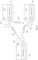
- Fig. 4 is a schematic representation of a wireless communication system including a transmitter 300, like a base station, and one or more receivers 302 1 to 302 n , like user devices, UEs.
- the transmitter 300 and the receivers 302 may communicate via a wireless communication links or channels 304a, 304b, 304c, like a radio link.
- the transmitter 300 may include one or more antennas ANT T or an antenna array having a plurality of antenna elements, a signal processor 300a and a transceiver 300b, coupled with each other.
- the receivers 302 include one or more antennas ANT R or an antenna array having a plurality of antennas, a signal processor 302a 1 , 302a n , and a transceiver 302b 1 , 302b n coupled with each other.
- the base station 300 and the UEs 302 may communicate via respective first wireless communication links 304a and 304b, like a radio link using the Uu interface, while the UEs 302 may communicate with each other via a second wireless communication link 304c, like a radio link using the PC5 interface.
- the system, the base station 300 and the one or more UEs 302 may operate in accordance with the inventive teachings described herein.
- Fig. 5 illustrates an approach for sending data from a transmitting UE A to a receiving UE B and to provide a feedback from the receiving UE B to the transmitting UE A, wherein the data sent by the transmitting UE A, also referred to as user A, may comprise user data as well as control data for the receiving UE B, also referred to as user B.
- Fig. 5 illustrates a design for a self-contained sidelink frame 400.
- the frame 400 has a duration from a start time t S to an end time t E .
- the frame 400 may be a transmission time interval as defined by the wireless communication system in which the users A and B communicate with each other over the sidelink communication interface, or it may be any interval for which the apparatus, like the transmitting receiver or user A has reserved resources for a transmission to the user B.
- the frame 400 may be, for example, a sub-frame, a transmission time interval, a certain slot within the sub-frame or a mini-slot. In any case, it is assumed that the transmission time associated with user A starts at time t S and ends at time t E .
- the transmission of data from the user A to the user B is only over a part of the frame duration T, for example until a time t T so that the actual transmission time T is from time t S to time t T and the duration from the time t T to the end of the frame t E may be used for a transmission from the user B to the user A and may be referred to as a remaining duration or remaining frame time R.
- a time t T so that the actual transmission time T is from time t S to time t T and the duration from the time t T to the end of the frame t E may be used for a transmission from the user B to the user A and may be referred to as a remaining duration or remaining frame time R.
- the user A transmits data to the user B during the transmission time T which includes control data C and user data D.
- the user A transmits the control data or control signaling C followed by a secondary signal D containing the payload data and/or additional signaling, like requesting channel state information and/or reference symbols CSI-RS. This may also be referred to as piggybacking the additional signaling on the data.
- the transmission of data from the user A to the user B is followed by a time gap R 1 during the remaining duration R of the frame 400 to allow the user B to process the received data and/or for performing a switching between reception and transmission mode at the user B.
- the user B sends the feedback F which may be a HARQ feedback including acknowledgement/non-acknowledgement messages, ACK, NACK, and/or additional feedback, such as a CSI, for example the CQI, RSSI (Received Signal Strength Indicator), RSRP (Received Signal Received Power), RSRQ (Reference Signal Received Quality) and in the case of MIMO RI (Rank Indicator) or PMI (Preferred Matrix Index).
- CSI for example the CQI, RSSI (Received Signal Strength Indicator), RSRP (Received Signal Received Power), RSRQ (Reference Signal Received Quality) and in the case of MIMO RI (Rank Indicator) or PMI (Preferred Matrix Index).
- the control signaling may be a physical sidelink control channel, PSCCH, which is modified so as to include the additional information whether the UE B has to provide feedback about the information or not.
- PSCCH physical sidelink control channel
- the control signaling C transmitted initially by user A at the beginning of the frame 400 includes an indication for the receiving UE B that the user B is to provide a feedback indicating a successful/non-successful reception of the control signaling and the data D.
- the feedback for the data transmitted by the user A or in addition to the feedback for this data, information about the channel between the user A and the user B over the sidelink may be provided as feedback F from the user B to the user A so as to allow, for example, user A to carry out a link adaption and power control.
- the feedback message may include a binary value indicating whether to increase or decrease a modulation encoding scheme, MCS, level for the next data transmission over the sidelink, and/or whether to adjust the power level by increasing or decreasing the transmit power for the next transmission over the sidelink by a certain amount, e.g. by steps of +1 dB or -1 dB.
- MCS modulation encoding scheme
- Fig. 5 shows one example for transmitting data from a user A to a user B using a modified frame 400 providing the time R at the end of the frame to allow the user B to transmit back to the user A the feedback within the duration of the frame 400 which may include, as mentioned above, the time for processing the receive data from the user A and/or a time for switching between receiving and transmitting at the user B as well as the time for performing the actual transmission of the feedback F.
- the frame transmitted from the user A to the user B may only include control information C and no user data or payload data D.
- Fig. 6 shows such a frame which is basically the same as the frame of Fig. 5 except that the payload data D is missing. Also, dependent on the amount of control signaling transmitted from the user A to the user B the transmission time T for the actual transmission of the user A may be shorter so that more time R is available for the user B.
- it can be used to send other large feedback reports, like
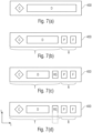
- Fig. 7 illustrates different examples for frames for transmitting data from user A to user B.
- Fig. 7(a) illustrates a conventional frame as it is currently used that may include control signaling and user data for the user B that is transmitted within the frame without providing any remaining time for the user B to send the feedback.
- a corresponding frame is be transmitted from the user B to the user A including the feedback information.
- This approach while being possible, is disadvantageous due to the increased latency for providing the feedback to the user A which may be especially disadvantageous in cases where the payload to be transmitted from user A to user B is time critical or delay critical, for example data associated with ULRCC services.
- Fig. 7 illustrates different examples for frames for transmitting data from user A to user B.
- Fig. 7(a) illustrates a conventional frame as it is currently used that may include control signaling and user data for the user B that is transmitted within the frame without providing any remaining time for the user B to send the feedback.
- a corresponding frame is be transmitted from the user B to the user A
- FIG. 7(b) illustrates the structure of the frame as described above with reference to Fig. 5 allowing for sufficient time R at the end of the frame for providing feedback from the user B to the user A, as mentioned above, feedback about the reception of the data at the user B or information about the channel state.
- Fig. 7(c) illustrates another frame structure including, during the transmission time T, in addition to the control signaling and the payload data also reference symbols RS, on the basis of which the user B may calculate the channel condition and provide information about the channel condition as feedback.
- Fig. 7(d) illustrates another example for providing the reference signals.
- CSI-RS may be used to estimate the channel in a wider bandwidth. This information better resources can be selected for subsequent transmissions.
- a first frame having a structure as in Fig. 6 may transmit signaling in its control section that a bundled or aggregated feedback is desired for a certain number n of subsequently sent data packets.
- the initial frame transmitted may be a frame as indicated in Fig. 5 including in addition to the control signaling indicative of the aggregated feedback to be provided already the first data packet.
- the subsequent frames may either be conventional sidelink frames as in Fig. 7(a) or inventive sidelink frames as described above in Figs. 5 and 6 and in Figs. 7(b) to 7(d) including data packets, and the final frame may be a frame as in Fig.
- the aggregated feedback may be an aggregated HARQ feedback or group-HARQ feedback, i.e., acknowledgement/non-acknowledgement messages may be fed back from the user B to the user A.
- the user A configures the user B to transmit the HARQ feedback after receiving the n-th data packet.
- the user B may send this information as a bitmap so that the feedback may include:
- Fig. 8 schematically illustrates the above-described aggregated feedback. It is assumed that four packets D 1 to D 4 of user data are transmitted from user A to user B and at only once the four packets are received, the user B is to return a feedback to user A about the four packets D 1 to D 4 .
- a first data packet D 1 is transmitted in accordance with one of the inventive frame structures which includes control signaling telling the user B that four packets are transmitted from the user A to the user B and once these four packets are completed, a feedback is to be returned.
- the second, third and fourth data packets D 2 to D 4 may be transmitted using one of the inventive frame structures or a conventional frame structure as in Fig.
- a frame structure as in Fig. 6 may be used including control signaling from the user A to the user B and having a remaining duration R sufficient to allow the user B to transmit the feedback F 1-4 to the user A for each of the data packets D 1 to D 4 .
- the feedback provided by the user B concerned the data included in the current transmission of frame received from user A.
- the feedback provided by user B using the above-described frame structure may concern a feedback about the successful/non-successful reception of data in an earlier frame, for example in a frame preceding the current frame immediately or with some additional frames therebetween.
- the above-described frame structure may be employed to provide the feedback from the user B in the next transmission n+1, or even later in the transmission n+2 or in the transmission n+3.
- This approach may be used for a HARQ feedback in case a time for processing the data transmitted by user A at the user B exceeds the remaining time R so that the actual feedback for the initial data packet is transmitted in one of the following transmissions n+1, n+2 or n+3.
- Fig. 9 illustrates an HARQ process using the frame structure with a transmission of the feedback for a data packet transmitted in transmission n being sent in the next transmission n+1.
- a user A sends data to a user B, and user B sends the acknowledgement/non-acknowledgment feedback back to the user A which does not refer to a currently received data packet but to a data packet received prior to the current transmission. More specifically, as it is depicted in Fig. 9 , initially in the frame F n , the user A transmits the data D 1 to the user B. It is assumed that no feedback is send at this time back to the user A.
- the signaling that no feedback is to be send may be handled in different ways:
- user A sends control data C 2 and payload data D 2 to the user B and the control data C 2 indicates to the user B that a feedback is to be transmitted to the user A for the preceding data packet D 1 . Accordingly, user B sends back the feedback F 1 within the remaining duration R of the frame F n+1 which has a frame structure 400 n+1 as described, for example, with reference to Fig. 5 .
- the feedback F 1 may be an acknowledgement message ACK, "A" causing the user A in the frame F n+2 to transmit the next data packet D 3 together with a request for a feedback about data packet D 2 using a frame structure 400 n+2 .
- the feedback F 1 indicates a non-acknowledgment "N"
- this may be due to the fact that the data D 1 was not successfully decoded at the user B or that the first transmission or first frame F n was completely missed at the user B.
- the user A receiving the non-acknowledgment feedback indicating a non-successful decoding of the data packet D 1 retransmits in frame F n+2 the data packet D 1 or performs any suitable retransmission, using the inventive frame structure 400' n+2 so that the user B may provide the feedback F 2 for the data packet D 2 received in frame F n+1 .
- user A sends in frame F n+2 using the inventive frame structure 400" n+2 resending the data packet D 1 and requesting feedback from the user B regarding the data packet D 1 during the frame F n+2 .
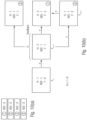
- the sidelink control information, SCI, transmitted in the physical sidelink control channel may be provided with additional fields, like a HARQ process number H, a new data indicator NDI that toggles with new data for the HARQ process, and a feedback indicator F.
- Fig. 10 illustrates the respective values for the new fields in the SCI at the user B, in case of the example of Fig. 9 .
- Fig. 10(a) illustrates the initial state of the HARQ processes at user B
- Fig. 10(b) illustrates how the fields H, NDI, F change during the transmissions or frames in Fig. 9 .
- H HARQ Process number
- F eedback Request number.
- Fig. 10(a) illustrates the initial HARQ process state. Before beginning the unicast transmission.
- the user A may transmit a frame including the data packet D 3 together with a request for a feedback for the data packet D 2 .
- the user A in frame F n+1 indicated that the data was not successfully decoded ("x"), in frame F n+2 the user A retransmits the data D 1 together with a request for a feedback regarding the transmission of the data packet D 2 which, when being successful, causes the user A to send the next data packet D 3 .
- control data and the user data have been sent at different times, i.e., using a TDM control, however, there is no limitation to a TDM control, rather, control data and user data may be sent at the same time on different resources in frequency, i.e., a FDM control may be applied, and the above described approach may be used by sending the feedback indicator in a previous control message.
- Fig. 11 shows an approach employing FDM control. Control data is transmitted in a first frequency band fc and user data is transmitted in a second frequency band fd. In a first frame F n , a control message, SCI, may be transmitted including the above-described feedback indicator F.
- the feedback indicator tells the user B whether feedback for the data D1 transmitted in frame F n is to be returned to the user A or not in the next frame F n+1 .
- the feedback indicator tells the user B that a feedback regarding the data D 1 is to be returned to the user A so that, in frame F n+1 , the data frequency band or data channel fd is configured such that a second data packet D 2 is transmitted during the transmission time T which is less than the frame duration so that during the remaining duration R, the feedback may be transmitted from the user B back to the user A.
- the feedback indication may be piggybacked in the data region, as is illustrated in Fig. 12.
- Fig. 12 is similar to Fig. 11 , except that the feedback indicator is contained in the data packet D 1 , which is sent from user A to user B.
- User B decodes data packet D 1 in frame F n and reads the feedback indicator, which tells the user B that a feedback regarding the data D 1 is to be returned to the user A so that, in frame F n+1 , the data frequency band or data channel fd is configured such that a second data packet D 2 is transmitted during the transmission time T which is less than the frame duration so that during the remaining duration R, the feedback may be transmitted from the user B back to the user A.
- mode 1 or mode 3 configuration vehicles being in the connected mode
- mode 2 or mode 4 configuration vehicles being in the idle mode
- the present invention is not limited to V2V communications or V2X communications, rather it is also applicable to any device-to-device communications, for example non-vehicular mobile users or stationary users that perform a sidelink communication, e.g., over the PC5 interface. Also in such scenarios, the inventive aspects described above may be employed.
- the wireless communication system may include a terrestrial network, or a non-terrestrial network, or networks or segments of networks using as a receiver an airborne vehicle or a spaceborne vehicle, or a combination thereof.
- a UE may comprise one or more of a mobile or stationary terminal, an IoT device, a ground based vehicle, an aerial vehicle, a drone, a building, or any other item or device provided with network connectivity enabling the item/device to communicate using the wireless communication system, like a sensor or actuator.
- a transmitter may comprise one or more of a macro cell base station, or a small cell base station, or a spaceborne vehicle, like a satellite or a space, or an airborne vehicle, like a unmanned aircraft system (UAS), e.g., a tethered UAS, a lighter than air UAS (LTA), a heavier than air UAS (HTA) and a high altitude UAS platforms (HAPs), or any transmission/reception point (TRP) enabling an item or a device provided with network connectivity to communicate using the wireless communication system.
- UAS unmanned aircraft system
- LTA lighter than air UAS
- HTA heavier than air UAS
- HAPs high altitude UAS platforms
- TRP transmission/reception point
- aspects of the described concept have been described in the context of an apparatus, it is clear that these aspects also represent a description of the corresponding method, where a block or a device corresponds to a method step or a feature of a method step. Analogously, aspects described in the context of a method step also represent a description of a corresponding block or item or feature of a corresponding apparatus.
- Various elements and features of the present invention may be implemented in hardware using analog and/or digital circuits, in software, through the execution of instructions by one or more general purpose or special-purpose processors, or as a combination of hardware and software.
- embodiments of the present invention may be implemented in the environment of a computer system or another processing system.
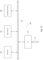
- Fig. 13 illustrates an example of a computer system 600.
- the units or modules as well as the steps of the methods performed by these units may execute on one or more computer systems 600.
- the computer system 600 includes one or more processors 602, like a special purpose or a general purpose digital signal processor.
- the processor 602 is connected to a communication infrastructure 604, like a bus or a network.
- the computer system 600 includes a main memory 606, e.g., a random access memory (RAM), and a secondary memory 608, e.g., a hard disk drive and/or a removable storage drive.
- the secondary memory 608 may allow computer programs or other instructions to be loaded into the computer system 600.
- the computer system 600 may further include a communications interface 610 to allow software and data to be transferred between computer system 600 and external devices.
- the communication may be in the from electronic, electromagnetic, optical, or other signals capable of being handled by a communications interface.
- the communication may use a wire or a cable, fiber optics, a phone line, a cellular phone link, an RF link and other communications channels 612.
- computer program medium and “computer readable medium” are used to generally refer to tangible storage media such as removable storage units or a hard disk installed in a hard disk drive.
- These computer program products are means for providing software to the computer system 600.
- the computer programs also referred to as computer control logic, are stored in main memory 606 and/or secondary memory 608. Computer programs may also be received via the communications interface 610.
- the computer program when executed, enables the computer system 600 to implement the present invention.
- the computer program when executed, enables processor 602 to implement the processes of the present invention, such as any of the methods described herein. Accordingly, such a computer program may represent a controller of the computer system 600.
- the software may be stored in a computer program product and loaded into computer system 600 using a removable storage drive, an interface, like communications interface 610.
- the implementation in hardware or in software may be performed using a digital storage medium, for example cloud storage, a floppy disk, a DVD, a Blue-Ray, a CD, a ROM, a PROM, an EPROM, an EEPROM or a FLASH memory, having electronically readable control signals stored thereon, which cooperate (or are capable of cooperating) with a programmable computer system such that the respective method is performed. Therefore, the digital storage medium may be computer readable.
- a digital storage medium for example cloud storage, a floppy disk, a DVD, a Blue-Ray, a CD, a ROM, a PROM, an EPROM, an EEPROM or a FLASH memory, having electronically readable control signals stored thereon, which cooperate (or are capable of cooperating) with a programmable computer system such that the respective method is performed. Therefore, the digital storage medium may be computer readable.
- Some embodiments not being according to the invention as claimed, comprise a data carrier having electronically readable control signals, which are capable of cooperating with a programmable computer system, such that one of the methods described herein is performed.
- embodiments of the present invention may be implemented as a computer program product with a program code, the program code being operative for performing one of the methods when the computer program product runs on a computer.
- the program code may for example be stored on a machine readable carrier.
- inventions comprise the computer program for performing one of the methods described herein, stored on a machine readable carrier.
- an embodiment of the inventive method is, therefore, a computer program having a program code for performing one of the methods described herein, when the computer program runs on a computer.
- a further embodiment, not being according to the invention as claimed is, therefore, a data carrier (or a digital storage medium, or a computer-readable medium) comprising, recorded thereon, the computer program for performing one of the methods described herein.
- a further embodiment not being according to the invention as claimed is, therefore, a data stream or a sequence of signals representing the computer program for performing one of the methods described herein. The data stream or the sequence of signals may for example be configured to be transferred via a data communication connection, for example via the Internet.
- a further embodiment, not being according to the invention as claimed comprises a processing means, for example a computer, or a programmable logic device, configured to or adapted to perform one of the methods described herein.
- a further embodiment, not being according to the invention as claimed comprises a computer having installed thereon the computer program for performing one of the methods described herein.
- a programmable logic device for example a field programmable gate array
- a field programmable gate array may cooperate with a microprocessor in order to perform one of the methods described herein.
- the methods are preferably performed by any hardware apparatus.
- V2X Vehicle-to-Everything 3GPP Third Generation Partnership Project
- D2D Device-to-Device ITS Intelligent Transport Services FR1, FR2 Frequency Range Designations
- Base Station eNB Evolved Node B (3G base station)
- UE User Equipment
- SCS Sub Carrier Spacing
- RB Resource Block PSCCH Physical Sidelink Control Channel
- PSSCH Physical Sidelink Shared Channel
- TTI Transmit Time Interval SCI Sidelink Control Information
- DCI Downlink Control Information
- CP Cyclic Prefix
- BWP Bandwidth Part CORESET Control Resource Set USS UE-Specific Search Space CSS Common Search Space RP Resource Pool
Landscapes
- Engineering & Computer Science (AREA)
- Signal Processing (AREA)
- Computer Networks & Wireless Communication (AREA)
- Quality & Reliability (AREA)
- Mobile Radio Communication Systems (AREA)
Claims (12)
- Appareil pour un système de communication sans fil,dans lequel l'appareil est configuré pour être connecté à au moins un dispositif d'utilisateur, UE, du système de communication sans fil à travers une liaison latérale pour une communication en liaison latérale avec l'au moins un UE,dans lequel, pour une transmission en monodiffusion à l'UE, l'appareil est configuré pour transmettre une trame de liaison latérale (Fn) présentant une certaine durée de trame, une première partie de la trame de liaison latérale comportant une signalisation de commande (C1) et une deuxième partie de la trame de liaison latérale comportant un paquet de données (D1), la trame de liaison latérale indiquant à l'UE s'il y a lieu de retourner une rétroaction à l'appareil, la rétroaction indiquant une réception fructueuse des données au niveau de l'UE et/ou une condition de canal de liaison latérale, etdans lequel, au cas où est souhaité le retour à partir de l'UE, l'appareil est configuré pour- transmettre, dans la deuxième partie de la trame de liaison latérale (Fn), une indication (FI) du fait que la rétroaction doit être prévue par l'UE, et- recevoir de l'UE, dans une trame de liaison latérale suivante (Fn+1), le retour (B) pour les données transmises dans la trame de liaison latérale, la trame de liaison latérale suivante (Fn+1) comportant une signalisation de commande (C2) et un paquet de données (D2), le paquet de données (D2) étant raccourci d'une durée restante (R), et la rétroaction (B) étant transmise pendant la durée restante (R) dans la trame de liaison latérale suivante (Fn+1).
- Appareil selon la revendication 1, dans lequel l'appareil est configuré pour- inclure, dans la première et/ou la deuxième partie de la trame de liaison latérale, un ou plusieurs signaux de référence, les signaux de référence étant utilisés au niveau de l'UE pour déterminer une ou plusieurs propriétés du canal de transmission de l'appareil à l'UE, telles qu'un état de canal, CSI, un CQI et/ou des informations d'indicateur de matrice de pré-codage (PMI) dans le cas de transmissions MIMO,- recevoir de l'UE des informations sur les propriétés de canal de transmission, et- adapter les paramètres de transmission, tels qu'un schéma de modulation et de codage, MCS, un pré-codage et/ou un niveau de puissance, en réponse aux propriétés de canal de transmission reçues.
- Appareil selon la revendication 2, dans lequel l'appareil est configuré pour transmettre les un ou plusieurs signaux de référence dans une première plage de fréquences et dans au moins une deuxième plage de fréquences, les fréquences dans la deuxième plage de fréquences étant supérieures aux fréquences dans la première plage de fréquences.
- Appareil selon l'une quelconque des revendications précédentes, dans lequel, au cas où il n'est pas souhaité de rétroaction de l'UE, l'appareil est configuré pour transmettre, dans la deuxième partie de la trame de liaison latérale, une indication qu'il n'y a pas lieu de prévoir un rétroaction par l'UE.
- Appareil pour un système de communication sans fil,dans lequel l'appareil est configuré pour être connecté à au moins un dispositif d'utilisateur, UE, du système de communication sans fil à travers une liaison latérale pour une communication en liaison latérale avec ledit au moins un UE,dans lequel, pour une transmission en monodiffusion à l'UE, l'appareil est configuré pour recevoir une trame de liaison latérale (Fn) présentant une certaine durée de trame, une première partie de la trame de liaison latérale comportant une signalisation de commande (C1) et une deuxième partie de la trame de liaison latérale comportant un paquet de données (D1), la trame de liaison latérale indiquant à l'UE s'il y a lieu de retourner une rétroaction à l'UE, la rétroaction indiquant une réception fructueuse des données au niveau de l'appareil et/ou une condition de canal de liaison latérale, etdans lequel, au cas où est souhaitée la rétroaction vers l'UE, l'appareil est configuré pour- recevoir, de la deuxième partie de la trame de liaison latérale (Fn), une indication (F1) indiquant que la rétroaction doit être prévue par l'appareil, et- déterminer et transmettre la rétroaction pour les données transmises dans la trame de liaison latérale à l'UE dans une trame de liaison latérale suivante (Fn+1), la trame de liaison latérale suivante comportant une signalisation de commande (C2) et un paquet de données (D2), le paquet de données (D2) étant raccourci d'une durée restante (R), et la rétroaction (B) étant transmise pendant la durée restante (R) dans la trame de liaison latérale suivante (Fn+1).
- Appareil selon la revendication 5, dans lequel l'appareil est configuré pour- récupérer, de la première et/ou de la deuxième partie de la trame, un ou plusieurs signaux de référence,- déterminer une ou plusieurs propriétés du canal de transmission de l'UE à l'appareil, telles qu'un état de canal, CSI, et- transmettre les informations sur les propriétés de canal de transmission à l'UE.
- Appareil selon l'une quelconque des revendications précédentes, dans lequel l'indication de rétroaction comporte un ou plusieurs parmi:- un seul bit pour une rétroaction, tel qu'un drapeau de nonrétroaction,- un nombre de processus HARQ,- une demande de rétroaction agrégée retournant un ensemble d'accusés/non-accusés de réception,- CSI, commande de puissance,- demande de CQI, RSSI, RSRP, RSRQ, RI, PMI.
- Appareil selon l'une quelconque des revendications précédentes, dans lequel la rétroaction indique une réception fructueuse/non fructueuse des données dans une trame précédant la trame, par exemple un ou plusieurs de ce qui suit:- une rétroaction HARQ comportant un message d'accusé de réception, ACK, et/ou un message de non-accusé de réception, NACK,- une rétroaction HARQ groupée ou agrégée,- une rétroaction HARQ de groupe après réception d'un groupe de paquets de données à l'aide de∘ un message ACK de groupe, ou∘ un message NACK à répétition sélective comportant un bitmap indiquant le paquet qui n'a pas été reçu et le paquet qui doit être retransmis, ou∘ un bitmap accusant réception de tous les paquets de données reçus de sorte que les paquets non indiqués soient retransmis automatiquement.
- Appareil selon l'une quelconque des revendications précédentes, dans lequel l'appareil est configuré pour fonctionner- selon un premier mode, par exemple le Mode 1 ou le Mode 3, pour une communication en liaison latérale, dans le premier mode, la planification des ressources pour la communication en liaison latérale avec les un ou plusieurs autres UE étant effectuée par une station de base, gNB, du système de communication sans fil, ou- selon un deuxième mode, par exemple le Mode 2 ou le Mode 4, pour une communication en liaison latérale avec un ou plusieurs autres UE, et pour planifier de manière autonome les ressources parmi un ensemble de ressources d'émission/ réception pour la communication en liaison latérale.
- Réseau de communication sans fil, comprenant un ou plusieurs appareils selon l'une quelconque des revendications 1 à 9.
- Procédé de transmission d'un UE émetteur à un UE récepteur dans un système de communication sans fil à travers une liaison latérale, le procédé comprenant le fait de:transmettre, par l'UE émetteur, une trame de liaison latérale (Fn) présentant une certaine durée de trame, une première partie de la trame de liaison latérale comportant une signalisation de commande (C1) et une deuxième partie de la trame de liaison latérale comportant un paquet de données (D1), la trame de liaison latérale indiquant à l'UE qu'il y a lieu de retourner une rétroaction à l'appareil, la rétroaction indiquant une réception fructueuse des données au niveau de l'UE et/ou une condition de canal de liaison latérale,transmettre, dans la deuxième partie de la trame de liaison latérale (Fn), une indication (F1) que la rétroaction doit être prévue par l'UE, etrecevoir, au niveau de l'UE émetteur, dans une trame de liaison latérale suivante (Fn+1), la rétroaction (B) de l'UE de réception pour les données transmises dans la trame de liaison latérale, la trame de liaison latérale suivante (Fn+1) comportant une signalisation de commande (C2) et un paquet de données (D2), le paquet de données (D2) étant raccourci d'une durée restante (R), et la rétroaction (B) étant transmise pendant la durée restante (R) dans la trame de liaison latérale suivante (Fn+1).
- Produit de programme informatique non transitoire comprenant un support lisible par ordinateur mémorisant des instructions qui, lorsqu'elles sont exécutées sur un ordinateur, réalisent le procédé selon la revendication 11.
Priority Applications (1)
| Application Number | Priority Date | Filing Date | Title |
|---|---|---|---|
| EP24208158.6A EP4510750A3 (fr) | 2018-09-27 | 2019-09-27 | Rétroaction de liaison latérale |
Applications Claiming Priority (2)
| Application Number | Priority Date | Filing Date | Title |
|---|---|---|---|
| EP18197380 | 2018-09-27 | ||
| PCT/EP2019/076290 WO2020065057A1 (fr) | 2018-09-27 | 2019-09-27 | Rétroaction de liaison latérale |
Related Child Applications (1)
| Application Number | Title | Priority Date | Filing Date |
|---|---|---|---|
| EP24208158.6A Division EP4510750A3 (fr) | 2018-09-27 | 2019-09-27 | Rétroaction de liaison latérale |
Publications (2)
| Publication Number | Publication Date |
|---|---|
| EP3858084A1 EP3858084A1 (fr) | 2021-08-04 |
| EP3858084B1 true EP3858084B1 (fr) | 2024-10-30 |
Family
ID=63787726
Family Applications (2)
| Application Number | Title | Priority Date | Filing Date |
|---|---|---|---|
| EP19773472.6A Active EP3858084B1 (fr) | 2018-09-27 | 2019-09-27 | Rétroaction de liaison latérale |
| EP24208158.6A Pending EP4510750A3 (fr) | 2018-09-27 | 2019-09-27 | Rétroaction de liaison latérale |
Family Applications After (1)
| Application Number | Title | Priority Date | Filing Date |
|---|---|---|---|
| EP24208158.6A Pending EP4510750A3 (fr) | 2018-09-27 | 2019-09-27 | Rétroaction de liaison latérale |
Country Status (6)
| Country | Link |
|---|---|
| US (3) | US11770208B2 (fr) |
| EP (2) | EP3858084B1 (fr) |
| JP (1) | JP7337918B2 (fr) |
| KR (1) | KR102661313B1 (fr) |
| CN (1) | CN112840735B (fr) |
| WO (1) | WO2020065057A1 (fr) |
Families Citing this family (20)
| Publication number | Priority date | Publication date | Assignee | Title |
|---|---|---|---|---|
| US10856345B2 (en) * | 2017-10-11 | 2020-12-01 | Qualcomm Incorporated | Methods and apparatus for device-to-device feedback |
| US12052200B2 (en) * | 2018-11-08 | 2024-07-30 | Lenovo (Beijing) Limited | Method and apparatus for DTX detection for sidelink groupcast transmission |
| US12058067B2 (en) * | 2019-01-11 | 2024-08-06 | Lg Electronics Inc. | Method and terminal for measuring channel in wireless communication system |
| WO2021016971A1 (fr) * | 2019-07-31 | 2021-02-04 | 北京小米移动软件有限公司 | Procédé et appareil de transmission de données |
| CN114586462A (zh) * | 2019-10-31 | 2022-06-03 | 华为技术有限公司 | 一种混合自动重传请求反馈方法及装置 |
| US11889502B2 (en) * | 2020-02-24 | 2024-01-30 | Qualcomm Incorporated | Two-stage feedback procedures |
| CN115669174B (zh) * | 2020-04-15 | 2025-03-21 | 诺基亚技术有限公司 | 免许可频谱中的节点之间的通信 |
| US11382131B2 (en) * | 2020-05-05 | 2022-07-05 | Telefonaktiebolaget Lm Ericsson (Publ) | Data signaling for high frequency networks |
| EP3952169A1 (fr) | 2020-08-05 | 2022-02-09 | Nokia Technologies Oy | Communication de noeud terminal à noeud terminal |
| US12021777B2 (en) * | 2020-09-02 | 2024-06-25 | Qualcomm Incorporated | Spatial relationship design for sidelink-assisted positioning |
| US11902960B2 (en) | 2020-09-28 | 2024-02-13 | Qualcomm Incorporated | Timer-based beacon and echo procedure |
| US11665672B2 (en) * | 2021-02-18 | 2023-05-30 | Qualcomm Incorporated | Techniques for channel state information feedback for sidelink communications |
| CN115550683B (zh) * | 2021-06-29 | 2024-12-20 | 华为技术有限公司 | 一种视频数据的传输方法及装置 |
| US11871416B2 (en) * | 2021-09-16 | 2024-01-09 | Qualcomm Incorporated | Multiplexing forward and reverse sidelink resource allocation for bidirectional communications |
| CN115835156B (zh) * | 2021-09-16 | 2025-07-25 | 宸芯科技股份有限公司 | 一种数据发送方法、装置、车联网设备及存储介质 |
| JP2024540947A (ja) * | 2021-10-21 | 2024-11-06 | 北京小米移動軟件有限公司 | サイドリンク通信方法、装置および記憶媒体 |
| US12470896B2 (en) * | 2022-12-22 | 2025-11-11 | Adeia Guides Inc. | Systems and methods for improving groupcast media streaming using metric information in device-to-device communications |
| WO2024147611A1 (fr) * | 2023-01-02 | 2024-07-11 | 엘지전자 주식회사 | Procédé et dispositif de mise en œuvre de communication de liaison latérale dans un spectre sans licence |
| JP2025140045A (ja) * | 2024-03-13 | 2025-09-29 | キヤノン株式会社 | 通信装置、通信方法、プログラム及び通信システム |
| JP2025140044A (ja) * | 2024-03-13 | 2025-09-29 | キヤノン株式会社 | 通信装置、通信方法及びプログラム |
Family Cites Families (20)
| Publication number | Priority date | Publication date | Assignee | Title |
|---|---|---|---|---|
| US8559946B2 (en) * | 2008-02-08 | 2013-10-15 | Qualcomm Incorporated | Discontinuous transmission signaling over an uplink control channel |
| KR101919797B1 (ko) * | 2011-03-18 | 2018-11-19 | 엘지전자 주식회사 | 장치-대-장치 통신 방법 및 장치 |
| CN107222301B (zh) * | 2011-09-23 | 2020-09-15 | Lg电子株式会社 | 对上行链路控制信息进行信道编码的方法和用户设备 |
| JP6122855B2 (ja) * | 2011-09-30 | 2017-04-26 | インターデイジタル パテント ホールディングス インコーポレイテッド | 縮小されたチャネル帯域幅を使用するデバイス通信 |
| WO2013095355A1 (fr) * | 2011-12-20 | 2013-06-27 | Intel Corporation | Service de diffusion groupée utilisant une sous-trame d'envoi individuel |
| CN104205690B (zh) | 2012-03-30 | 2018-03-13 | Lg电子株式会社 | 在无线通信系统中接收控制信息的方法和设备 |
| US20160360541A1 (en) * | 2014-02-12 | 2016-12-08 | Lg Electronics Inc. | Method for transmitting/receiving signal in wireless communication system, and apparatus therefor |
| JP6621758B2 (ja) | 2014-11-14 | 2019-12-18 | 株式会社Nttドコモ | ユーザ装置、フィードバック制御方法、及び再送制御方法 |
| CN117222049A (zh) * | 2015-04-08 | 2023-12-12 | 苹果公司 | 用于增强的设备到设备(d2d)的控制信令机制 |
| US10841117B2 (en) * | 2015-04-15 | 2020-11-17 | Lg Electronics Inc. | Method for performing feedback by terminal in wireless communication system and apparatus therefor |
| RU2694586C1 (ru) * | 2015-08-25 | 2019-07-16 | Идак Холдингз, Инк. | Кадрирование, диспетчеризация и синхронизация в системах беспроводной связи |
| JP6603958B2 (ja) * | 2015-10-23 | 2019-11-13 | オッポ広東移動通信有限公司 | 滞留セルの選択方法及び装置 |
| WO2017074298A1 (fr) * | 2015-10-26 | 2017-05-04 | Fujitsu Limited | Station de base et dispositif sans fil utilisés dans un système de communication sans fil |
| US10334586B2 (en) * | 2016-01-22 | 2019-06-25 | Qualcomm Incorporated | Hybrid automatic repeat request feedback for unicast sidelink communications |
| US10277367B2 (en) * | 2016-04-01 | 2019-04-30 | Motorola Mobility Llc | Method and apparatus for scheduling uplink transmissions with reduced latency |
| US10367677B2 (en) * | 2016-05-13 | 2019-07-30 | Telefonaktiebolaget Lm Ericsson (Publ) | Network architecture, methods, and devices for a wireless communications network |
| US10390362B2 (en) * | 2016-06-06 | 2019-08-20 | Qualcomm Incorporated | Sidelink-centric subframe for wireless communication |
| US10383137B2 (en) * | 2016-07-28 | 2019-08-13 | Qualcomm Incorporated | Mechanisms for signaling out-of-coverage sidelink devices in wireless communication |
| EP3583716B1 (fr) * | 2017-02-17 | 2025-01-15 | Telefonaktiebolaget LM Ericsson (PUBL) | Signalisation de ressources de liaison latérale |
| US11722262B2 (en) * | 2017-07-21 | 2023-08-08 | Lg Electronics Inc. | Method and apparatus for transmitting feedback by terminal receiving signal from another terminal in wireless communication system |
-
2019
- 2019-09-27 JP JP2021517591A patent/JP7337918B2/ja active Active
- 2019-09-27 WO PCT/EP2019/076290 patent/WO2020065057A1/fr not_active Ceased
- 2019-09-27 EP EP19773472.6A patent/EP3858084B1/fr active Active
- 2019-09-27 CN CN201980063833.3A patent/CN112840735B/zh active Active
- 2019-09-27 EP EP24208158.6A patent/EP4510750A3/fr active Pending
- 2019-09-27 KR KR1020217012551A patent/KR102661313B1/ko active Active
-
2021
- 2021-03-23 US US17/209,763 patent/US11770208B2/en active Active
-
2023
- 2023-08-14 US US18/233,730 patent/US12155472B2/en active Active
-
2024
- 2024-10-31 US US18/933,555 patent/US20250167915A1/en active Pending
Also Published As
| Publication number | Publication date |
|---|---|
| JP2022511372A (ja) | 2022-01-31 |
| US20230388047A1 (en) | 2023-11-30 |
| KR20210066878A (ko) | 2021-06-07 |
| JP7337918B2 (ja) | 2023-09-04 |
| EP4510750A2 (fr) | 2025-02-19 |
| EP3858084A1 (fr) | 2021-08-04 |
| EP4510750A3 (fr) | 2025-04-23 |
| US20250167915A1 (en) | 2025-05-22 |
| CN112840735A (zh) | 2021-05-25 |
| US12155472B2 (en) | 2024-11-26 |
| US11770208B2 (en) | 2023-09-26 |
| US20210306089A1 (en) | 2021-09-30 |
| CN112840735B (zh) | 2024-08-16 |
| KR102661313B1 (ko) | 2024-04-30 |
| WO2020065057A1 (fr) | 2020-04-02 |
Similar Documents
| Publication | Publication Date | Title |
|---|---|---|
| US12155472B2 (en) | Sidelink feedback | |
| JP7768178B2 (ja) | カバレージ内およびカバレージ外シナリオでのサイドリンクのharq | |
| US11950326B2 (en) | Advanced feedback in sidelink | |
| US20240348374A1 (en) | Low latency harq protocol for urllc services | |
| US12413345B2 (en) | V2X HARQ process management | |
| KR20220073818A (ko) | Nr v2x 재전송 절차 | |
| US12231248B2 (en) | URLLC DAI and LTI |
Legal Events
| Date | Code | Title | Description |
|---|---|---|---|
| STAA | Information on the status of an ep patent application or granted ep patent |
Free format text: STATUS: UNKNOWN |
|
| STAA | Information on the status of an ep patent application or granted ep patent |
Free format text: STATUS: THE INTERNATIONAL PUBLICATION HAS BEEN MADE |
|
| PUAI | Public reference made under article 153(3) epc to a published international application that has entered the european phase |
Free format text: ORIGINAL CODE: 0009012 |
|
| STAA | Information on the status of an ep patent application or granted ep patent |
Free format text: STATUS: REQUEST FOR EXAMINATION WAS MADE |
|
| 17P | Request for examination filed |
Effective date: 20210319 |
|
| AK | Designated contracting states |
Kind code of ref document: A1 Designated state(s): AL AT BE BG CH CY CZ DE DK EE ES FI FR GB GR HR HU IE IS IT LI LT LU LV MC MK MT NL NO PL PT RO RS SE SI SK SM TR |
|
| DAV | Request for validation of the european patent (deleted) | ||
| DAX | Request for extension of the european patent (deleted) | ||
| RAP3 | Party data changed (applicant data changed or rights of an application transferred) |
Owner name: FRAUNHOFER-GESELLSCHAFT ZUR FOERDERUNG DER ANGEWANDTEN FORSCHUNG E.V. |
|
| STAA | Information on the status of an ep patent application or granted ep patent |
Free format text: STATUS: EXAMINATION IS IN PROGRESS |
|
| 17Q | First examination report despatched |
Effective date: 20230208 |
|
| GRAP | Despatch of communication of intention to grant a patent |
Free format text: ORIGINAL CODE: EPIDOSNIGR1 |
|
| STAA | Information on the status of an ep patent application or granted ep patent |
Free format text: STATUS: GRANT OF PATENT IS INTENDED |
|
| GRAJ | Information related to disapproval of communication of intention to grant by the applicant or resumption of examination proceedings by the epo deleted |
Free format text: ORIGINAL CODE: EPIDOSDIGR1 |
|
| STAA | Information on the status of an ep patent application or granted ep patent |
Free format text: STATUS: EXAMINATION IS IN PROGRESS |
|
| RIC1 | Information provided on ipc code assigned before grant |
Ipc: H04W 72/542 20230101ALI20240318BHEP Ipc: H04L 5/00 20060101ALI20240318BHEP Ipc: H04L 1/1829 20230101ALI20240318BHEP Ipc: H04L 1/00 20060101ALI20240318BHEP Ipc: H04W 76/14 20180101AFI20240318BHEP |
|
| INTG | Intention to grant announced |
Effective date: 20240404 |
|
| GRAP | Despatch of communication of intention to grant a patent |
Free format text: ORIGINAL CODE: EPIDOSNIGR1 |
|
| STAA | Information on the status of an ep patent application or granted ep patent |
Free format text: STATUS: GRANT OF PATENT IS INTENDED |
|
| INTC | Intention to grant announced (deleted) | ||
| INTG | Intention to grant announced |
Effective date: 20240510 |
|
| GRAS | Grant fee paid |
Free format text: ORIGINAL CODE: EPIDOSNIGR3 |
|
| GRAA | (expected) grant |
Free format text: ORIGINAL CODE: 0009210 |
|
| STAA | Information on the status of an ep patent application or granted ep patent |
Free format text: STATUS: THE PATENT HAS BEEN GRANTED |
|
| AK | Designated contracting states |
Kind code of ref document: B1 Designated state(s): AL AT BE BG CH CY CZ DE DK EE ES FI FR GB GR HR HU IE IS IT LI LT LU LV MC MK MT NL NO PL PT RO RS SE SI SK SM TR |
|
| REG | Reference to a national code |
Ref country code: GB Ref legal event code: FG4D |
|
| REG | Reference to a national code |
Ref country code: CH Ref legal event code: EP |
|
| REG | Reference to a national code |
Ref country code: IE Ref legal event code: FG4D |
|
| REG | Reference to a national code |
Ref country code: DE Ref legal event code: R096 Ref document number: 602019061172 Country of ref document: DE |
|
| P01 | Opt-out of the competence of the unified patent court (upc) registered |
Free format text: CASE NUMBER: APP_58455/2024 Effective date: 20241025 |
|
| REG | Reference to a national code |
Ref country code: NL Ref legal event code: FP |
|
| REG | Reference to a national code |
Ref country code: LT Ref legal event code: MG9D |
|
| PG25 | Lapsed in a contracting state [announced via postgrant information from national office to epo] |
Ref country code: IS Free format text: LAPSE BECAUSE OF FAILURE TO SUBMIT A TRANSLATION OF THE DESCRIPTION OR TO PAY THE FEE WITHIN THE PRESCRIBED TIME-LIMIT Effective date: 20250228 Ref country code: PT Free format text: LAPSE BECAUSE OF FAILURE TO SUBMIT A TRANSLATION OF THE DESCRIPTION OR TO PAY THE FEE WITHIN THE PRESCRIBED TIME-LIMIT Effective date: 20250228 Ref country code: HR Free format text: LAPSE BECAUSE OF FAILURE TO SUBMIT A TRANSLATION OF THE DESCRIPTION OR TO PAY THE FEE WITHIN THE PRESCRIBED TIME-LIMIT Effective date: 20241030 |
|
| PG25 | Lapsed in a contracting state [announced via postgrant information from national office to epo] |
Ref country code: FI Free format text: LAPSE BECAUSE OF FAILURE TO SUBMIT A TRANSLATION OF THE DESCRIPTION OR TO PAY THE FEE WITHIN THE PRESCRIBED TIME-LIMIT Effective date: 20241030 |
|
| REG | Reference to a national code |
Ref country code: AT Ref legal event code: MK05 Ref document number: 1738201 Country of ref document: AT Kind code of ref document: T Effective date: 20241030 |
|
| PG25 | Lapsed in a contracting state [announced via postgrant information from national office to epo] |
Ref country code: BG Free format text: LAPSE BECAUSE OF FAILURE TO SUBMIT A TRANSLATION OF THE DESCRIPTION OR TO PAY THE FEE WITHIN THE PRESCRIBED TIME-LIMIT Effective date: 20241030 |
|
| PG25 | Lapsed in a contracting state [announced via postgrant information from national office to epo] |
Ref country code: ES Free format text: LAPSE BECAUSE OF FAILURE TO SUBMIT A TRANSLATION OF THE DESCRIPTION OR TO PAY THE FEE WITHIN THE PRESCRIBED TIME-LIMIT Effective date: 20241030 |
|
| PG25 | Lapsed in a contracting state [announced via postgrant information from national office to epo] |
Ref country code: NO Free format text: LAPSE BECAUSE OF FAILURE TO SUBMIT A TRANSLATION OF THE DESCRIPTION OR TO PAY THE FEE WITHIN THE PRESCRIBED TIME-LIMIT Effective date: 20250130 |
|
| PG25 | Lapsed in a contracting state [announced via postgrant information from national office to epo] |
Ref country code: AT Free format text: LAPSE BECAUSE OF FAILURE TO SUBMIT A TRANSLATION OF THE DESCRIPTION OR TO PAY THE FEE WITHIN THE PRESCRIBED TIME-LIMIT Effective date: 20241030 Ref country code: LV Free format text: LAPSE BECAUSE OF FAILURE TO SUBMIT A TRANSLATION OF THE DESCRIPTION OR TO PAY THE FEE WITHIN THE PRESCRIBED TIME-LIMIT Effective date: 20241030 Ref country code: GR Free format text: LAPSE BECAUSE OF FAILURE TO SUBMIT A TRANSLATION OF THE DESCRIPTION OR TO PAY THE FEE WITHIN THE PRESCRIBED TIME-LIMIT Effective date: 20250131 |
|
| PG25 | Lapsed in a contracting state [announced via postgrant information from national office to epo] |
Ref country code: PL Free format text: LAPSE BECAUSE OF FAILURE TO SUBMIT A TRANSLATION OF THE DESCRIPTION OR TO PAY THE FEE WITHIN THE PRESCRIBED TIME-LIMIT Effective date: 20241030 |
|
| PG25 | Lapsed in a contracting state [announced via postgrant information from national office to epo] |
Ref country code: RS Free format text: LAPSE BECAUSE OF FAILURE TO SUBMIT A TRANSLATION OF THE DESCRIPTION OR TO PAY THE FEE WITHIN THE PRESCRIBED TIME-LIMIT Effective date: 20250130 |
|
| PG25 | Lapsed in a contracting state [announced via postgrant information from national office to epo] |
Ref country code: SM Free format text: LAPSE BECAUSE OF FAILURE TO SUBMIT A TRANSLATION OF THE DESCRIPTION OR TO PAY THE FEE WITHIN THE PRESCRIBED TIME-LIMIT Effective date: 20241030 |
|
| PG25 | Lapsed in a contracting state [announced via postgrant information from national office to epo] |
Ref country code: DK Free format text: LAPSE BECAUSE OF FAILURE TO SUBMIT A TRANSLATION OF THE DESCRIPTION OR TO PAY THE FEE WITHIN THE PRESCRIBED TIME-LIMIT Effective date: 20241030 |
|
| PG25 | Lapsed in a contracting state [announced via postgrant information from national office to epo] |
Ref country code: EE Free format text: LAPSE BECAUSE OF FAILURE TO SUBMIT A TRANSLATION OF THE DESCRIPTION OR TO PAY THE FEE WITHIN THE PRESCRIBED TIME-LIMIT Effective date: 20241030 |
|
| PG25 | Lapsed in a contracting state [announced via postgrant information from national office to epo] |
Ref country code: RO Free format text: LAPSE BECAUSE OF FAILURE TO SUBMIT A TRANSLATION OF THE DESCRIPTION OR TO PAY THE FEE WITHIN THE PRESCRIBED TIME-LIMIT Effective date: 20241030 |
|
| PG25 | Lapsed in a contracting state [announced via postgrant information from national office to epo] |
Ref country code: SK Free format text: LAPSE BECAUSE OF FAILURE TO SUBMIT A TRANSLATION OF THE DESCRIPTION OR TO PAY THE FEE WITHIN THE PRESCRIBED TIME-LIMIT Effective date: 20241030 |
|
| PG25 | Lapsed in a contracting state [announced via postgrant information from national office to epo] |
Ref country code: CZ Free format text: LAPSE BECAUSE OF FAILURE TO SUBMIT A TRANSLATION OF THE DESCRIPTION OR TO PAY THE FEE WITHIN THE PRESCRIBED TIME-LIMIT Effective date: 20241030 |
|
| PG25 | Lapsed in a contracting state [announced via postgrant information from national office to epo] |
Ref country code: IT Free format text: LAPSE BECAUSE OF FAILURE TO SUBMIT A TRANSLATION OF THE DESCRIPTION OR TO PAY THE FEE WITHIN THE PRESCRIBED TIME-LIMIT Effective date: 20241030 |
|
| REG | Reference to a national code |
Ref country code: DE Ref legal event code: R097 Ref document number: 602019061172 Country of ref document: DE |
|
| PLBE | No opposition filed within time limit |
Free format text: ORIGINAL CODE: 0009261 |
|
| STAA | Information on the status of an ep patent application or granted ep patent |
Free format text: STATUS: NO OPPOSITION FILED WITHIN TIME LIMIT |
|
| PG25 | Lapsed in a contracting state [announced via postgrant information from national office to epo] |
Ref country code: SE Free format text: LAPSE BECAUSE OF FAILURE TO SUBMIT A TRANSLATION OF THE DESCRIPTION OR TO PAY THE FEE WITHIN THE PRESCRIBED TIME-LIMIT Effective date: 20241030 |
|
| 26N | No opposition filed |
Effective date: 20250731 |
|
| PGFP | Annual fee paid to national office [announced via postgrant information from national office to epo] |
Ref country code: DE Payment date: 20250729 Year of fee payment: 7 |
|
| PGFP | Annual fee paid to national office [announced via postgrant information from national office to epo] |
Ref country code: NL Payment date: 20250927 Year of fee payment: 7 |
|
| PGFP | Annual fee paid to national office [announced via postgrant information from national office to epo] |
Ref country code: GB Payment date: 20250927 Year of fee payment: 7 |
|
| PGFP | Annual fee paid to national office [announced via postgrant information from national office to epo] |
Ref country code: FR Payment date: 20250926 Year of fee payment: 7 |