EP3858463A1 - Installation et procédé pour récupérer des substances gazeuses à partir de courants gazeux - Google Patents
Installation et procédé pour récupérer des substances gazeuses à partir de courants gazeux Download PDFInfo
- Publication number
- EP3858463A1 EP3858463A1 EP19865634.0A EP19865634A EP3858463A1 EP 3858463 A1 EP3858463 A1 EP 3858463A1 EP 19865634 A EP19865634 A EP 19865634A EP 3858463 A1 EP3858463 A1 EP 3858463A1
- Authority
- EP
- European Patent Office
- Prior art keywords
- module
- stream
- adsorption
- outlet
- concentration
- Prior art date
- Legal status (The legal status is an assumption and is not a legal conclusion. Google has not performed a legal analysis and makes no representation as to the accuracy of the status listed.)
- Withdrawn
Links
Images


Classifications
-
- B—PERFORMING OPERATIONS; TRANSPORTING
- B01—PHYSICAL OR CHEMICAL PROCESSES OR APPARATUS IN GENERAL
- B01D—SEPARATION
- B01D53/00—Separation of gases or vapours; Recovering vapours of volatile solvents from gases; Chemical or biological purification of waste gases, e.g. engine exhaust gases, smoke, fumes, flue gases, aerosols
- B01D53/02—Separation of gases or vapours; Recovering vapours of volatile solvents from gases; Chemical or biological purification of waste gases, e.g. engine exhaust gases, smoke, fumes, flue gases, aerosols by adsorption, e.g. preparative gas chromatography
- B01D53/04—Separation of gases or vapours; Recovering vapours of volatile solvents from gases; Chemical or biological purification of waste gases, e.g. engine exhaust gases, smoke, fumes, flue gases, aerosols by adsorption, e.g. preparative gas chromatography with stationary adsorbents
- B01D53/047—Pressure swing adsorption
- B01D53/0476—Vacuum pressure swing adsorption
-
- B—PERFORMING OPERATIONS; TRANSPORTING
- B01—PHYSICAL OR CHEMICAL PROCESSES OR APPARATUS IN GENERAL
- B01D—SEPARATION
- B01D53/00—Separation of gases or vapours; Recovering vapours of volatile solvents from gases; Chemical or biological purification of waste gases, e.g. engine exhaust gases, smoke, fumes, flue gases, aerosols
- B01D53/02—Separation of gases or vapours; Recovering vapours of volatile solvents from gases; Chemical or biological purification of waste gases, e.g. engine exhaust gases, smoke, fumes, flue gases, aerosols by adsorption, e.g. preparative gas chromatography
- B01D53/04—Separation of gases or vapours; Recovering vapours of volatile solvents from gases; Chemical or biological purification of waste gases, e.g. engine exhaust gases, smoke, fumes, flue gases, aerosols by adsorption, e.g. preparative gas chromatography with stationary adsorbents
- B01D53/047—Pressure swing adsorption
-
- B—PERFORMING OPERATIONS; TRANSPORTING
- B01—PHYSICAL OR CHEMICAL PROCESSES OR APPARATUS IN GENERAL
- B01D—SEPARATION
- B01D51/00—Auxiliary pretreatment of gases or vapours to be cleaned
- B01D51/10—Conditioning the gas to be cleaned
-
- B—PERFORMING OPERATIONS; TRANSPORTING
- B01—PHYSICAL OR CHEMICAL PROCESSES OR APPARATUS IN GENERAL
- B01D—SEPARATION
- B01D53/00—Separation of gases or vapours; Recovering vapours of volatile solvents from gases; Chemical or biological purification of waste gases, e.g. engine exhaust gases, smoke, fumes, flue gases, aerosols
- B01D53/002—Separation of gases or vapours; Recovering vapours of volatile solvents from gases; Chemical or biological purification of waste gases, e.g. engine exhaust gases, smoke, fumes, flue gases, aerosols by condensation
-
- B—PERFORMING OPERATIONS; TRANSPORTING
- B01—PHYSICAL OR CHEMICAL PROCESSES OR APPARATUS IN GENERAL
- B01D—SEPARATION
- B01D53/00—Separation of gases or vapours; Recovering vapours of volatile solvents from gases; Chemical or biological purification of waste gases, e.g. engine exhaust gases, smoke, fumes, flue gases, aerosols
- B01D53/02—Separation of gases or vapours; Recovering vapours of volatile solvents from gases; Chemical or biological purification of waste gases, e.g. engine exhaust gases, smoke, fumes, flue gases, aerosols by adsorption, e.g. preparative gas chromatography
- B01D53/04—Separation of gases or vapours; Recovering vapours of volatile solvents from gases; Chemical or biological purification of waste gases, e.g. engine exhaust gases, smoke, fumes, flue gases, aerosols by adsorption, e.g. preparative gas chromatography with stationary adsorbents
- B01D53/0407—Constructional details of adsorbing systems
-
- B—PERFORMING OPERATIONS; TRANSPORTING
- B01—PHYSICAL OR CHEMICAL PROCESSES OR APPARATUS IN GENERAL
- B01D—SEPARATION
- B01D53/00—Separation of gases or vapours; Recovering vapours of volatile solvents from gases; Chemical or biological purification of waste gases, e.g. engine exhaust gases, smoke, fumes, flue gases, aerosols
- B01D53/02—Separation of gases or vapours; Recovering vapours of volatile solvents from gases; Chemical or biological purification of waste gases, e.g. engine exhaust gases, smoke, fumes, flue gases, aerosols by adsorption, e.g. preparative gas chromatography
- B01D53/04—Separation of gases or vapours; Recovering vapours of volatile solvents from gases; Chemical or biological purification of waste gases, e.g. engine exhaust gases, smoke, fumes, flue gases, aerosols by adsorption, e.g. preparative gas chromatography with stationary adsorbents
- B01D53/047—Pressure swing adsorption
- B01D53/053—Pressure swing adsorption with storage or buffer vessel
-
- B—PERFORMING OPERATIONS; TRANSPORTING
- B01—PHYSICAL OR CHEMICAL PROCESSES OR APPARATUS IN GENERAL
- B01D—SEPARATION
- B01D53/00—Separation of gases or vapours; Recovering vapours of volatile solvents from gases; Chemical or biological purification of waste gases, e.g. engine exhaust gases, smoke, fumes, flue gases, aerosols
- B01D53/26—Drying gases or vapours
- B01D53/265—Drying gases or vapours by refrigeration (condensation)
-
- B—PERFORMING OPERATIONS; TRANSPORTING
- B01—PHYSICAL OR CHEMICAL PROCESSES OR APPARATUS IN GENERAL
- B01D—SEPARATION
- B01D2253/00—Adsorbents used in seperation treatment of gases and vapours
- B01D2253/10—Inorganic adsorbents
- B01D2253/106—Silica or silicates
- B01D2253/108—Zeolites
-
- B—PERFORMING OPERATIONS; TRANSPORTING
- B01—PHYSICAL OR CHEMICAL PROCESSES OR APPARATUS IN GENERAL
- B01D—SEPARATION
- B01D2257/00—Components to be removed
- B01D2257/10—Single element gases other than halogens
- B01D2257/108—Hydrogen
-
- B—PERFORMING OPERATIONS; TRANSPORTING
- B01—PHYSICAL OR CHEMICAL PROCESSES OR APPARATUS IN GENERAL
- B01D—SEPARATION
- B01D2257/00—Components to be removed
- B01D2257/30—Sulfur compounds
- B01D2257/304—Hydrogen sulfide
-
- B—PERFORMING OPERATIONS; TRANSPORTING
- B01—PHYSICAL OR CHEMICAL PROCESSES OR APPARATUS IN GENERAL
- B01D—SEPARATION
- B01D2257/00—Components to be removed
- B01D2257/50—Carbon oxides
-
- B—PERFORMING OPERATIONS; TRANSPORTING
- B01—PHYSICAL OR CHEMICAL PROCESSES OR APPARATUS IN GENERAL
- B01D—SEPARATION
- B01D2257/00—Components to be removed
- B01D2257/50—Carbon oxides
- B01D2257/504—Carbon dioxide
-
- B—PERFORMING OPERATIONS; TRANSPORTING
- B01—PHYSICAL OR CHEMICAL PROCESSES OR APPARATUS IN GENERAL
- B01D—SEPARATION
- B01D2257/00—Components to be removed
- B01D2257/70—Organic compounds not provided for in groups B01D2257/00 - B01D2257/602
- B01D2257/702—Hydrocarbons
- B01D2257/7022—Aliphatic hydrocarbons
- B01D2257/7025—Methane
-
- B—PERFORMING OPERATIONS; TRANSPORTING
- B01—PHYSICAL OR CHEMICAL PROCESSES OR APPARATUS IN GENERAL
- B01D—SEPARATION
- B01D2259/00—Type of treatment
- B01D2259/40—Further details for adsorption processes and devices
- B01D2259/40007—Controlling pressure or temperature swing adsorption
-
- Y—GENERAL TAGGING OF NEW TECHNOLOGICAL DEVELOPMENTS; GENERAL TAGGING OF CROSS-SECTIONAL TECHNOLOGIES SPANNING OVER SEVERAL SECTIONS OF THE IPC; TECHNICAL SUBJECTS COVERED BY FORMER USPC CROSS-REFERENCE ART COLLECTIONS [XRACs] AND DIGESTS
- Y02—TECHNOLOGIES OR APPLICATIONS FOR MITIGATION OR ADAPTATION AGAINST CLIMATE CHANGE
- Y02C—CAPTURE, STORAGE, SEQUESTRATION OR DISPOSAL OF GREENHOUSE GASES [GHG]
- Y02C20/00—Capture or disposal of greenhouse gases
- Y02C20/20—Capture or disposal of greenhouse gases of methane
-
- Y—GENERAL TAGGING OF NEW TECHNOLOGICAL DEVELOPMENTS; GENERAL TAGGING OF CROSS-SECTIONAL TECHNOLOGIES SPANNING OVER SEVERAL SECTIONS OF THE IPC; TECHNICAL SUBJECTS COVERED BY FORMER USPC CROSS-REFERENCE ART COLLECTIONS [XRACs] AND DIGESTS
- Y02—TECHNOLOGIES OR APPLICATIONS FOR MITIGATION OR ADAPTATION AGAINST CLIMATE CHANGE
- Y02C—CAPTURE, STORAGE, SEQUESTRATION OR DISPOSAL OF GREENHOUSE GASES [GHG]
- Y02C20/00—Capture or disposal of greenhouse gases
- Y02C20/40—Capture or disposal of greenhouse gases of CO2
Definitions
- the present invention can be included in the technical field of the treatment of any gas flow made up of atmospheric gases, particularly, from the treatment of combustion exhaust gases, among other mixtures.
- Said installation and method can be applied for the recovery of any gaseous substance which is forming part of the gas flow to be separated.
- the object of the invention relates to an installation, the control system thereof and a method for recovering substances, in particular greenhouse gases, mainly carbon dioxide (CO 2 ), from gas flows, depleting said gas flows in the recovered substances.
- substances in particular greenhouse gases, mainly carbon dioxide (CO 2 )
- CO 2 carbon dioxide
- One of the ways to carry out reductions in the emissions of said gases is to use means for separating the gaseous substances contained in gas flows with the objective of capturing the greenhouse gases.
- Patent US8052777 "Vessel, system, and process for minimizing unequal flow distribution”.
- Chambers for PSA Pressure Swing Adsorption
- These systems can contain one or more walls that make up different beds of adsorbent material, leaving two different sides in the shape of a bell to diffuse the flow in the chamber.
- Patent US8268043B2 Modular compact adsorption bed
- Patent US6994111 Toroidal vessel for uniform, plug-flow fluid distribution applications
- This design is an improvement of conventional adsorption chambers, whose work is of the "plug-flow fluids applications” type, processes with an inlet and an outlet in which a uniform distribution of the flow inside is desired (applications chromatography or adsorption bed processes).
- the proposed chamber is of the toroidal type that allows an efficient laminar distribution.
- Patent US1683567A2 "Reactor with an annular adsorptively active bed and an annular inert bed"
- the system is made up of multi-cameras.
- One of the internal rings or sub-chambers of the system houses the adsorbent material, while the other chamber contains a material inert to the adsorption process that is created in the first, both separated by a permeable gas or liquid.
- the gas inlet to be processed is introduced through the feed and is processed while it flows to the outermost ring, being extracted through the connection to the outside.
- Patent EP1500424A1 Pressure Swing Adsorption system multi-chamber canister
- An initial chamber receives the compressed fluid for the process and distributes it evenly to the sieves with adsorbent material type Zeolite.
- the chambers have multiple internal compartments to, among other objectives, maintain a uniform temperature in chambers, this also serves to promote adsorption and not have large thermal gradients that would disturb the uniformity of the gas concentration in the chamber.
- Chamber aimed at improving the PSA adsorption process initially designed to treat atmospheric air that will be fed through the compressor that can be seen in the figure in the upper part of the chamber. Chamber not concentrically compartmentalized but with parallel axis arrangement.
- the system describes the PSA process directly without the ability to allow control over the concentration of the outlet streams (27) or (44) of the system proposed as the device of the present invention.
- Patent US5931022 Air purification process with thermal regeneration
- alumina-type adsorbent such as Zeolite 13X (negatively charged aluminosilicates)
- PSA processes for purification of gas streams by removing CO2.
- a process of regeneration of the adsorbent is proposed, according to which the adsorbent bed will be heated to a certain temperature, eliminating the stored remains of CO2 and H2O from the material. This process is necessary since, despite the initial conditioning, a small percentage of water always enters in vapor form, which after certain adsorption / desorption cycles succumbs the adsorbent capacity of the Zeolite.
- the proposed process consists of a periodic heating after certain cycles of adsorption / desorption, heating.
- Patent US6362122 Heating the composite of zeolite and binder with aqueous caustic solution; washing, drying and roasting; decarboxylation "
- Process for the regeneration of Zeolite-type composite materials after their use in adsorption, for example in adsorption of carbonaceous compounds The process consists of putting the material in contact with a caustic solution, such as sodium hydroxide, isolating the compound, washing with water, drying and, finally, calcining. The result is a regenerated material.
- a caustic solution such as sodium hydroxide
- the contact with the aqueous caustic solution is carried out between 20 and 110°C for a time of 1 to 48 hours, subsequently it is washed with water and dried.
- the calcination phase is carried out between 500 and 700°C for a time of 1 to 24 hours.
- Regeneration of adsorbent materials Zeolites among the suitable ones.
- Regeneration proposal with caustic solution process sequence: Contact with solution under isolation conditions (20 / 110°C; 1/48 hours). Contact with H2O and subsequent drying. Calcination (500/700 ° C; 1/24 hours). It is a PTSA (Pressure and Thermal Swing Adsorption) process, completely different from the PSA process proposed as the device of the present invention, which does not require cyclic regeneration.
- PTSA Pressure and Thermal Swing Adsorption
- Patent US6402814 Adsorption, regeneration, depressurization cycle
- the described regeneration process which involves depressurization of the chambers after adsorption, includes a heating phase, during which the porous bed is purged with a gas, and a cooling phase, during which the porous bed is purged with a cooling gas.
- the process refers to the treatment of beds in TSA (Thermal Swing Adsorption) processes with alumina or zeolite-type adsorbents (X, L, XLA, etc.) to purify air currents (removing CO2 and [H2O] v) destined for plants. located downstream of distillation or cryogenics.
- TSA Thermal Swing Adsorption
- Patent EP1574246A1 Periodic high temperature regeneration of thermal swing adsorption systems
- Regeneration in the TSA process Proposed process: Initially it is adsorbed by contacting the gas stream with a selective adsorbent to remove the desired components from the stream. Once the adsorption is finished, it is heated by heating at a temperature in the range of (40-400) °C. Chamber and porous bed cooling down to the initial process temperature. Periodically, and not between cycles, a second regeneration is carried out preferably between 200 and 400°C, also, in a second phase of experimentation, the temperature being strictly 50°C or more above that of the first regeneration (first regeneration: between 40 and 400 ° C). It is a TSA process, completely different from the PSA process proposed as the device of the present invention, which does not require cyclic regeneration.
- Patent US5968234A Adsorption of water and carbon dioxide onto solid adsorbent to separate from feed air to be purified, periodically regenerating adsorbent with portion of nitrogen-containing compressed gas from the air separation unit (ASU)"
- Regeneration system for adsorbent materials type Zeolite X, Y, A, silica-gel, chabazite, mordenite and mixtures of them when they begin to present low yields in the adsorption of CO2.
- a current enriched in N2 is used, specifically using the current formed by the molecules that the material does not capture during the adsorption phase.
- This regenerative stream undergoes a multistage compression process before regenerating, which provides it with a considerable pressure increase.
- Patent US5938819A Preferential adsorption of carbon dioxide at low operating pressure followed by regeneration of adsorbent by purging with dry air; simplification
- the adsorbent is of a type rich in natural Na.
- the removal in the regeneration of the residual CO2 that collapses and depletes the adsorbent material is carried out at moderate pressures, close to atmospheric, and with a high volume of air.
- the CO2 performs a leaching process (in metallurgy: extraction from a mineral of a species of interest by means of reagents) and leaves the adsorbent bed, returning the adsorbent capacity. Evaluating results with different modes of operation it is determined that the large amount of air is more influential than high pressure.
- PSA process to adsorb CO2 and generate effluent rich in CH4 through the use of material rich in natural Na. In the regeneration phase, instead of high pressures to attack the material, it subjects it to moderate pressures but high volumes of air.
- the system describes the PSA process directly without the ability to allow control over the concentration of the outlet streams (27) or (44) of the system proposed as the device of the present invention.
- Patent US0061747 “Dynamic and continuous control for pressure swing adsorption"
- Parameter control process to regulate PSA gaseous flow treatment system.
- an air flow is treated to separate O2 from N2 by means of Zeolites.
- the objective of this system is to monitor in real time at least one flow parameter (P, T, flow,% of some component, T dew, humidity, etc.).
- the monitored parameters are compared with threshold values (critical values that, upon detection, will trigger actions on the system components).
- the system of this patent consists of a PSA block, where adsorption is carried out, and a "sentinel” block, which continuously monitors the desired parameters.
- This control system is valid for CO2 capture systems (exhaust from plants, factories, etc.), NH3 or H2S (refineries).
- Control of PSA systems refers to the separation of N2 from O2 in air currents. Control system equally valid for capturing CO2, NH3 or H2S. Integration of components, which are, adjustment system, control system and alarm system. The control system describes one of the possible control systems applicable to PSA processes. Completely different from that proposed in the device of the present invention, in which the sentinel block is not necessary to control all the control and alarm parameters in real time and simultaneously.
- Patent US4472177A Control system and method for air fractionation by vacuum swing adsorption
- VSA process control Structures are presented for the control of valves and switches (switches) that interconnect a programmable controller with the separation system.
- a variable time system is presented that controls each of the process stages carried out by the separation process control system.
- the specific case treated is a VSA process, with two parallel adsorption columns, two pretreatment chambers downstream of the columns and two upstream desorbed chambers.
- the PSA process proposed for the present invention uses vacuum systems to produce desorption by pressure, it also uses entrainment through explosive injections inside the desorption chambers to achieve the extraction of adsorbed gases in the shortest possible time. in the porous material, as well as the extraction by excess pressure from the adsorption pressure to the atmospheric pressure, therefore the systems are completely different.
- Patent US4696680 Metal and apparatus for the selective separation of gaseous coal gasification products by pressure swing adsorption
- Process sequence The mixture is introduced into the first adsorption column and this is pressurized so that the gases are sequentially adsorbed. After reaching the desired pressure level, the chamber begins to depressurize. With the decrease in pressure, the set of gases (H2, CO, CH4) is evacuated first. Continuing the descent to Patm and reaching negative relative pressures, the acid group (CO2, H2S) is evacuated. The two sequential outputs are derived to different process lines. By repeating the process for each set of gases, pressurizing and depressurizing appropriately, H2, CO and CH4 are separated completely and with high levels of purity on the one hand and CO2 and H2S on the other.
- H2, CO and CH4 are separated completely and with high levels of purity on the one hand and CO2 and H2S on the other.
- Patent WO 2009/073928 A plant and process for recovering carbon dioxide
- PSA system with adsorption material type Zeolite X or Y Originally for treatment with gaseous effluents with a high percentage of CO2 (> 50%), such as vents from soft drink carbonation plants.
- the inlet conditions to the system are between (10-90°C) and (1-2) bar.
- Desorption is carried out in a vacuum range between (2-50) kPa or (0.02-0.5) bar.
- As an extra energy recovery process it sends the CO2-poor stream that leaves the chamber during adsorption, which will be between (10-40°C), to cool the liquid refrigerant that works by cooling the rings of the vacuum pumps.
- the system aims to simulate a pseudo-continuum in which the two chambers of the system work alternately, one in adsorption and the other in desorption.
- the transition of the chamber that ends desorption, at P approx. 0.02 bar, up to atmospheric pressure, is carried out by interconnecting both chambers, since pressures are balanced because one is depressurized and the other is 2 bar.
- this type of purge is usually carried out of the "Heavy purge" type with product streams with a high concentration of CO2 or "Light purge" when they are waste streams with a lower concentration of CO2).
- PSA system PSA system, adsorbent material Zeolites X or Y, treatment of CO2 concentration in gaseous effluents with high concentrations of this gas (> 50%).
- Adsorption processes Between 10 and 40°C and between 1 and 2 bar.
- Desorption process In vacuum between 0.02 and 0.5 bar. It appears to meet the false continuum conditions by alternating adsorption / desorption chambers. Novel characteristics: Depressurization is carried out by interconnection between chambers. In the WO 2009/073928 system, both chambers are connected, so it is a parallel derivative and the equalization process ends when the pressures in both chambers are equalized. In our device of the invention, recirculation occurs through the vacuum pumps to the desired concentration of CO2.
- the system describes the PSA process allowing equalization between chambers but without the ability to allow control over the concentration of the output currents (27) or (44) of the system proposed as the device of the present invention.
- Patent US3885927 "Removal of carbon dioxide from gas streams"
- Adsorption system with Zeolites X It is recommended to apply low temperatures in the process, starting at around 20°C, since it assumes that during the process there will be an increase due to compressions and other pretreatment phases. Defines the range as admissible if it is between 30 and 80°C. It makes special reference to the fact that the CO2 in the initial gas stream has a partial pressure greater than 25 mbar. It is more a scientific-technical patent for research than for engineering development, so the presentation of a specific operating procedure is not appreciated. The system describes the PSA process directly without the ability to allow control over the concentration of the outlet streams (27) or (44) of the system proposed as the device of the present invention.
- Patent US5689974A Metal and apparatus for pre-purification for air cryogenic separation plant
- the method includes the steps of: Adsorption: At defined pressure and temperatures between 10 and 45°C. Depressurization from P adsorption. Followed by phases of heating, cooling and repressurization. It is recommended to carry out the adsorption with introduction of the flow into the chamber at speeds between 0.05 and 0.4 m / s.
- the chamber will have an initial tray with the appropriate adsorbent to remove the moisture from the flow and another tray to capture the CO2.
- the system describes the PTSA process directly without the ability to allow control over the concentration of the output streams (27) or (44) of the system proposed as a device of the present invention.
- Patent US5906675 Air purification process
- PSA adsorption process Alternating three chambers in parallel, working respectively on adsorption, desorption and regeneration. The cameras have five levels to capture the compounds.
- the system describes the PTSA process directly without the ability to allow control over the concentration of the third or fifth output streams of the system proposed as a device of the present invention.
- Patent US6106593A Purification of air
- TSA process Division of the chambers into three divisions (Activated Alumina, 13X Zeolite and X Zeolite). The system describes the PSA process allowing equalization between chambers but without the ability to allow control over the concentration of the output currents (27) or (44) of the system proposed as the device of the present invention.
- Patent EP1226860B1 Metal of operating a thermal swing adsorption system and corresponding apparatus
- TSA adsorption process Chambers divided into differentiated sections with different adsorbents. The moisture will be captured with silica gel, alumina or activated alumina. The CO2 will be adsorbed by zeolite 13 X. The adsorption is recommended to be carried out at temperatures between 10 and 50°C.
- the system describes the PSA process allowing equalization between chambers but without the ability to allow control over the concentration of the output currents (27) or (44) of the system proposed as the device of the present invention.
- Patent US6273939 "Process for purifying a gas stream of its N2O impurities"
- TSA process to purify gaseous streams, such as air, mainly from N2O and traces of CO2 or C2H4.
- the adsorbent material used for the removal is Zeolite (preferably Si / AI ratio 1 to 1.5), carrying it out at temperatures between -40 and 80°C.
- TSA process to increase reliability of industrial plants.
- Main objective Removal of N2O from outgoing streams. It uses Zeolites as adsorbing material.
- the system describes the TSA process without the ability to allow control over the concentration of the output streams (27) or (44) of the system proposed as the device of the present invention.
- Patent EP0449576A1 "Purifying fluids by adsorption"
- TSA process Division of the chambers into three divisions (Activated Alumina, 13X Zeolite and X Zeolite). The system describes the PSA process allowing equalization between chambers but without the ability to allow control over the concentration of the output currents (27) or (44) of the system proposed as the device of the present invention.
- Patent US4770676 "Recovery of Methane from Land Fill Gas"
- Integrated PTA-PSA system capable of separating currents formed by the mixture of CH4 (30-70%) and CO2 (70-30%) and other traces of hydrocarbons in series.
- the first stage separates impurities by TSA adsorption and the second by PSA adsorption separates CH4 from CO2.
- PSA adsorption separates CH4 from CO2.
- the system describes a first TSA adsorption process that separates impurities followed by a second PSA process that separates CH4 from CO2. Designed for different gaseous streams, it does not allow equalization between chambers and neither does it have the ability to allow control over the concentration of the output streams (27) or (44) of the system proposed as a device of the present invention.
- Patent US20030047037A1 "Process for Removal of Carbon Dioxide for Use in Producing Direct Reduced Iron"
- PSA adsorption system formed by several columns in parallel with several adsorption layers made up of different solid adsorbent materials. Desorption is carried out by countercurrent vacuum.
- the system describes a PSA adsorption process that separates the CO2 from the gas stream but does not have the capacity to allow control over the concentration of the outlet streams (27) or (44) of the system proposed as a device for the present invention.
- Patent application ES 2407584A2 "Process for Removal of Carbon Dioxide for Use in Producing Direct Reduced Iron"
- PTSA adsorption system consisting of several columns in parallel using 13X Zeolites and / or Active Carbon as adsorbent material. Desorption is carried out by vacuum favoring extraction through heating cycles.
- the system describes a PTSA adsorption process that separates CO2 from the gas stream. It does not have the capacity to allow control over the concentration of the outlet streams (27) or (44) of the system proposed as the device of the present invention and is based on the use of a different PSA process.
- the present invention describes a device and a method for recovering gaseous substances from gas flows. Said method is based on performing the PSA adsorption/desorption process of the gas flow although by means of an inert adsorbent porous material selective to the gaseous substance to be separated, performed under operating conditions and by means of a method which enables efficiencies similar to the other existing systems at very competitive costs in comparison.
- the invention is applicable to a multitude of gaseous substances, although substances which are within the group of greenhouse gases are preferred, mainly carbon dioxide, although the invention is also viable for recovering other greenhouse effect substances, such as water vapor, suspended particles, nitrogen oxides and sulfur oxides.
- the method of the invention is based on a cycle of two or three sequential phases first comprising a treatment of the gases to be separated (module 1), second, a separation of gases (module 2) and third, a purification of the separated gas (module 3), the latter being optional depending on the characteristics of the gas flow enriched with the substance to be separated (as seen in Figure 1 ).
- Module 1 accommodates the gases entering this phase in pressure, temperature and composition, such that from a first inlet flow (1) it gives the result of two outlet flows, a first dry gas flow prepared to enter the second phase of gas separation (13) and a second outlet flow made up of the first removed gases, mainly suspended particles, water vapor and sulfur oxides (12).
- Module 2 by means of a process of separation and concentration by physical and chemical PSA adsorption, obtains from the first outlet flow (13) coming from module 1 two outlet flows: a third outlet flow (27) with a concentration of the gaseous substances to be extracted greater than those of the first inlet flow, and a fourth outlet flow (16) with a concentration of the gaseous substances to be extracted lower than those of the first inlet flow (13).
- module 3 by means of a process of separation and concentration by physical and chemical PSA adsorption similar to that of the second phase, although adapted to the composition of the gas flow to be treated, which obtains from the third outlet flow coming from the previous phase (27) two outlet flows: a fifth outlet flow (44) with a concentration of the gaseous substances to be extracted greater than those of the third outlet flow coming from the previous phase, and a sixth outlet flow (34) with a concentration of the gaseous substances to be extracted lower than those of the third outlet flow coming from the previous phase.
- the method can have the three previous modules, only the first two, be iterative, repeating any of the three previous modules in several steps, such that the first outlet flow (13) from module 1 constitutes the inlet flow of each module 2; and the third outlet flow (27) of each module 2 is the inlet flow to each module 3.
- the second outlet flow (12) from module 1 will be managed either as liquid waste or it will be able to be neutralized with bases such as NaOH or KOH, for the chemical stabilization thereof prior to being evacuated.
- the fourth (16) and sixth (34) outlet flows, being gaseous, will be managed according to the content thereof as value-added atmospheric gases or they will be released directly to the outside, and they will be biologically inert.
- the inlet flow (1) to module 1 can come from any flow comprising greenhouse gases, preferably at least one gas flow of combustion exhaust, hereinafter referred to as exhaust flow, for example, from thermal power plants with combustion of fossil fuels, biomass combustion plants, boilers that use fossil fuels or biomass to produce primary energy, etc.
- said inlet flow (1) is directed, as the first inlet flow to module 1, in order to carry out the first gas treatment phase in which the temperature and pressure are controlled in order to dry said flow by removing water, nitrogen and sulfur oxides, unburned substances and other solids in suspension, preparing the first outlet flow (13) for the injection thereof into module 2, in which the gas-separation process is carried out, with a composition which enables the operation under design conditions thereof according to the specifications of the adsorbent material.
- the second outlet flow (12) incorporates the separated water, the sulfur oxides, the unburned substances, partially the nitrogen oxides and other solids in suspension removed from the inlet gas flow (1).
- Module 2 treats the first outlet flow (13) from module 1 by means of a PSA adsorption/desorption process to separate the gases selected, enriching the third outlet flow (27) from module 2.
- the separation of gases occurs according to the selectivity of the adsorption process which has a certain adsorbent porous solid.
- the porous material used is active and selective against CO 2 and CO.
- the adsorption and desorption processes are performed in one or more adsorption/desorption reactors (14), in series, the adsorption process acting first, followed by that of PSA desorption, indefinitely repeating these processes in an alternating manner.
- adsorption/desorption reactors (14) In order to achieve a continuous operation of module 2, it is necessary to double the number of adsorption/desorption reactors (14), such that while half performs the adsorption process, the other half performs the PSA desorption process working in parallel.
- the first outlet flow (13) flows through the inner and outer surfaces of the adsorbent porous material arranged inside the adsorption/desorption reactors.
- the fourth outlet flow (16) is depleted in the selected gases and can be released to the outside with a composition very similar to that of the outside atmosphere, or by trying to have it recovered as industrial gases.
- the selected gases remain inside the adsorption/desorption reactors (14) adhered by means of Van der Waals forces, weak bonds and hydrogen bonds, among other forces of physical/chemical origin which are present.
- the adsorption process ends when the adsorbent porous material inside the adsorption/desorption reactors (14) becomes saturated and stops adsorbing the selected gases.
- the adsorption/desorption reactors (14) which perform the adsorption process are connected to the first outlet flow (13) from module 1 and are isolated from the PSA desorption system.
- the adsorption/desorption reactors (14) are isolated from the first outlet flow (13) from module 1 and are connected to the vacuum system which will enable the extraction of the gases adhered to the adsorbent porous material contained therein in order to enrich the third outlet gas flow (27) from module 2, enriched in the selected gases.
- the fourth outlet flow (16) from module 2 consists of the gas flow depleted in the selected gases coming from the adsorption/desorption reactors (14) which are performing the adsorption process, which will be able to be managed as atmospheric gases with added value, or it will be emitted directly to the outside atmosphere if it is biologically inert.
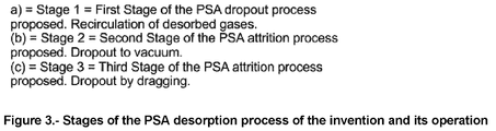
- the desorbed gas stream follows three different stages. First, see Figure 3 .
- the flow (21) is reinjected into the inlet gas flow to module 1, while the control system (45) of the system as a whole has it.
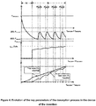
- the gases are accumulated in several buffer tanks for storage before leaving this phase, constituting the third outlet gas flow (27) from module 2, ending when it is possible to desorb approximately the same mass of selected gases that was initially adsorbed during the adsorption process ( Figure 3 describes the evolution of the key parameters during the PSA desorption process proposed in the present invention).
- the third step is repeated several times, as many as necessary to finish the second step, interrupting it, consisting of the reinjection of the gases desorbed and accumulated in the aforementioned tanks, for the injection thereof, as a flow (24) into the adsorption/desorption reactors (14) which are performing the PSA desorption process in an explosive manner, when the pressure thereof reaches a threshold value below a predetermined vacuum (approximately 80%), in order to pull the largest number of molecules from the selected gases and improve the behavior of the vacuum pumps used to perform the PSA desorption process.
- a predetermined vacuum approximately 80%
- module 3 based on the previous PSA adsorption/desorption process will be included.
- the operation of the module 3 will be similar and in series to the operation of the previous module 2, using as inlet gas flow the third outlet flow (27) enriched in the selected gases coming from module 2, using the same (or different) adsorbent porous material as the one used in module 2, provided that it is selective towards the gases selected for the separation and purification thereof.
- the sixth outlet gas flow (34) from the third gas purification phase may be reinjected to the adsorption/desorption reactors (31) which are performing the adsorption process in both module 2 and module 3; or be emitted directly to the outside atmosphere, depending on the composition thereof and whether or not it is biologically inert, as determined through the control system (45) of the invention.
- modules 2 and 3 will each have half of the adsorption/desorption reactors (14), (31) performing the adsorption process, while the other half will be performing the PSA desorption process.
- the control system (4) will alternate the operation thereof, achieving that half of the adsorption/desorption reactors (14), (31) of each module are performing the adsorption process at all times, continuously and without affecting the flow rate of the first inlet flow (1) to module 1.
- control system (45) will attempt to adjust the adsorption (t adsorption ) and desorption (t desorption ) times as much as possible, such that it will always meet the condition that t desorption ⁇ t adsorption in each of modules 2 and 3.
- the threshold points or values of the concentration of the selected gases in the desorbed flows (27) and (44), the concentration of the selected gases in the inlet flow to the system (1), the amount of water and other greenhouse gases present in the inlet flow to the system (1), the pressure and temperature conditions thereof, the mass and/or volumetric concentrations thereof; and the adsorption and desorption times of the adsorption/desorption reactors (14), (31) of modules 2 and 3 are, apart from multiple signals internal to the system as a whole, the main inputs which govern the control system (45) of the invention.
- the proposed device and method can, in theory, be used at any pressure and temperature, although, depending on the features, known in the state of the art, of the PSA adsorption/desorption systems using porous materials as adsorbent material, pressures below 10 bar(g) have been selected as the operating pressure range, and operating temperatures not higher than 50 °C, in order to protect the porous material used, obtaining an acceptable performance of the system as a whole and reducing the operation and maintenance costs.
- the system will try to optimize the adsorption process by maximizing the amount of the selected gases such that the adsorbed amount is maximized as much as possible, exceeding 95% of the amount present in the first inlet flow to the system and as close as possible to 100%.
- the operating pressure and temperature parameters of each of the three modules are selected, while with the mass concentration of the gases selected to be separated during the complete process, the different steps of the PSA desorption process will then be performed in modules 2 and 3 (optional), with the aim of achieving the mass concentration of the gases to be separated selected for the desired concentration and/or separation thereof, by means of reinjection processes in different points of the systems which make up the three modules, in order to achieve adsorption of the selected gases as much as possible in order to be separated from the main inlet gas flow (1) to module 1, increasing the adsorption and desorption yields of the system as a whole, by means of a complex control system (45).
- the method of the invention favors synergy between companies since the by-products of the method can be acquired as raw material by other companies.
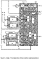
- An inlet gas flow (1) mainly coming from fossil fuel combustion systems for obtaining primary energy, enters module 1 for the analysis thereof, modification in pressure, temperature and content in other greenhouse gases, impurities and water vapor.
- This flow (1) is mobilized from the installation in which it is generated by an impulsion system (2) and is led by means of a system of pipes for the inlet and treatment thereof in module 1, constituting the gas flow (3) the characteristics of which are similar to those of the flow (1), but with a constant flow rate in accordance with the features of the control system (45) of the invention.
- the flow (3) has the following concentrations: CO 2 (1% - 25%), water vapor (0% - 25%), O 2 (0% - 35%) and other, N 2 , Ar, other greenhouse gases, unburned substances, ashes, etc., in accordance with the features of the previous combustion installation.
- the temperature range is between 60 °C and 800 °C and pressure is slightly above atmospheric pressure.
- the control system (45) depending on the characteristics of the flow (1) will manage the equipment of module 1 and the operation thereof in order to optimize the operation of the system as a whole.
- the gas flow (3) is treated in a first group of gas exchangers (4) in order to reach a temperature of around 40 °C or less.
- the first group of exchangers uses water, air or any fluid (i) in order to cool the flow (3), obtaining an outlet coolant flow (iii) in accordance with the legal limits for the treatment or evacuation to the outside thereof.
- This gas flow is joined by the gas flow (21) coming from module 2, which will be explained later, constituting the flow (7), which is compressed to pressures below 10 bar(g) in the compression system (8), at the outlet of which the gas flow (9) prepared for the inlet thereof into the drying system (10) is obtained.
- the drying system (10) removes the water present in the flow (around 99.9%), obtaining the first outlet flow (13) from module 1 for the sending thereof to module 2.
- the flow (13) is modified to the temperature (20 °C - 45 °C), pressure (1 - 9 bar(m)) and moisture (Approx. 0%) in order to optimize the adsorption process as much as possible.
- the drying system is cooled by a coolant fluid similar to the one used in the heat exchange group (4), using inlet (ii) and outlet (iv) flows in accordance with the legal limits for the treatment or evacuation thereof to the outside.
- the drying system (10) produces a second outlet flow (11) in which the condensed water coming from the flow (9), other sulfur oxides, unburned substances, ash and other greenhouse gases are removed.
- the flows (6) and (11) join together and constitute the liquid flow (12) which is the second outlet flow from module 1, which is treated prior to the evacuation outside thereof or for the subsequent recovery thereof.
- module 1 is adjusted by means of the control system (45) adapting the operation thereof at all times to the needs of the adsorbent material of modules 2 and 3; and the characteristics of the flow (1).
- the outlet flow (13) from module 1 is injected into module 2 in the adsorption/desorption reactors (14) which are performing the adsorption process, according to the instructions of the control system (45). After passing through these adsorption/desorption reactors (14), the outlet flow of each one (15) is directed to a single outlet conduit from module 2 to be returned to module 1 in which, as flow (16) it is released to the outside (if it is not biologically active) or to the evacuation installation in the combustion system from which the flow (1) is initially taken.
- the outlet flow of the gases located inside the adsorption/desorption reactors (14) constitutes the flow (17), which has an enrichment in the selected gases for the variable separation thereof over time depending on the vacuum extraction process, going from a CO 2 concentration of 0.4% to approximately 65% - 85% depending on the characteristics of the flow (1).
- the flow (17) is extracted and driven by the compressor (20) in order to favor the injection thereof as flow (21) to module 1 for the mixing thereof with the flow (5) during the first phase of the desorption process described above, ending the function thereof when the control system (45) so determines.
- the flow (17) becomes the flow (22) which is stored in the first buffer tank (23) of module 2.
- the rest passes as flow (25) to the second buffer tank (26) of module 2 from which the flow (27) is obtained for the extraction thereof to the outside or for the injection thereof as inlet flow to module 3.
- the flow (24) starts from the first buffer tank (23) of module 2 and is used as a pulling flow in the third phase of the PSA desorption process described above and is injected directly into the adsorption/desorption reactors (14) which are performing the desorption process.
- module 2 is adjusted by means of the control system (45) adapting the operation of the active systems located in module 1 at all times to the needs of average and maximum CO 2 concentration in the outlet flow from module 2 and for the purpose of optimizing the desorption process of the adsorption/desorption reactors (14) which perform the desorption process in module 2.
- the flows (33) and (36) are explained below.
- each adsorption/desorption reactor (32) After passing through these adsorption/desorption reactors (31) the outlet flow from each adsorption/desorption reactor (32) is directed for the injection thereof to the other adsorption/desorption reactors as flow (33) for the mixture thereof with the flow (29) or it is carried by means of an outlet conduit from module 3 to be returned to module 1 in which, as flow (34) it is released to the outside (if it is not biologically active) or to the evacuation installation in the combustion system from which the flow (1) is initially taken, according to what is indicated by the control system (45) of the invention.
- the outlet flow of the gases located inside the adsorption/desorption reactors constitutes the flow (39), which has an enrichment in the selected gases for the variable separation thereof over time depending on the vacuum extraction process, going from a CO 2 concentration of 65% - 85% to approximately 95% - 100% depending on the characteristics of the flow (1).
- the flow (39) is extracted and driven by the compressor (37) in order to favor the injection thereof as flow (36) to the flow (28) in order to constitute flow (29) during the first phase of the desorption process described above, ending the function thereof when the control system (45) so determines.
- the flow (35) becomes the flow (39) which is stored in the first buffer tank (40) of module 3.
- the rest goes as flow (42) to the second buffer tank (43) of module 3 from which the flow (44) is obtained for the extraction thereof to the outside.
- the flow (41) starts from the first buffer tank (40) of module 3 and is used as a pulling flow in the third phase of the PSA desorption process described above and is injected directly into the adsorption/desorption reactors (31) which are performing the desorption process.
- module 3 is adjusted by means of the control system (45) adapting the operation of the active systems located in module 1 at all times to the needs of average and maximum CO 2 concentration in the outlet flow from module 3 and for the purpose of optimizing the desorption process of the adsorption/desorption reactors which perform the desorption process in module 3.
Landscapes
- Chemical & Material Sciences (AREA)
- Chemical Kinetics & Catalysis (AREA)
- Engineering & Computer Science (AREA)
- Analytical Chemistry (AREA)
- General Chemical & Material Sciences (AREA)
- Oil, Petroleum & Natural Gas (AREA)
- Physics & Mathematics (AREA)
- Thermal Sciences (AREA)
- Separation Of Gases By Adsorption (AREA)
Applications Claiming Priority (2)
| Application Number | Priority Date | Filing Date | Title |
|---|---|---|---|
| ES201830944A ES2751176B2 (es) | 2018-09-29 | 2018-09-29 | Instalación y procedimiento para recuperar sustancias gaseosas a partir de corrientes gaseosas |
| PCT/ES2019/070601 WO2020065107A1 (fr) | 2018-09-29 | 2019-09-11 | Installation et procédé pour récupérer des substances gazeuses à partir de courants gazeux |
Publications (2)
| Publication Number | Publication Date |
|---|---|
| EP3858463A1 true EP3858463A1 (fr) | 2021-08-04 |
| EP3858463A4 EP3858463A4 (fr) | 2022-06-08 |
Family
ID=69937782
Family Applications (1)
| Application Number | Title | Priority Date | Filing Date |
|---|---|---|---|
| EP19865634.0A Withdrawn EP3858463A4 (fr) | 2018-09-29 | 2019-09-11 | Installation et procédé pour récupérer des substances gazeuses à partir de courants gazeux |
Country Status (4)
| Country | Link |
|---|---|
| US (1) | US11986766B2 (fr) |
| EP (1) | EP3858463A4 (fr) |
| ES (1) | ES2751176B2 (fr) |
| WO (1) | WO2020065107A1 (fr) |
Cited By (1)
| Publication number | Priority date | Publication date | Assignee | Title |
|---|---|---|---|---|
| WO2024200279A1 (fr) * | 2023-03-28 | 2024-10-03 | Volkswagen Aktiengesellschaft | Procédé de séparation de gaz modulaire, système de dispositif de séparation de gaz modulaire et dispositif de séparation de gaz modulaire |
Families Citing this family (2)
| Publication number | Priority date | Publication date | Assignee | Title |
|---|---|---|---|---|
| CN113713556A (zh) * | 2021-09-02 | 2021-11-30 | 东北大学 | 基于碳减排的大气气态污染物一体化处理方法 |
| US11980841B2 (en) | 2022-05-04 | 2024-05-14 | International Business Machines Corporation | Two-system gas stream separation |
Family Cites Families (89)
| Publication number | Priority date | Publication date | Assignee | Title |
|---|---|---|---|---|
| US61747A (en) | 1867-02-05 | manning | ||
| US1683567A (en) * | 1924-06-25 | 1928-09-04 | Moody Lewis Ferry | Hydraulic turbine |
| US3430418A (en) * | 1967-08-09 | 1969-03-04 | Union Carbide Corp | Selective adsorption process |
| US3564816A (en) * | 1968-12-30 | 1971-02-23 | Union Carbide Corp | Selective adsorption process |
| US3944400A (en) * | 1973-11-23 | 1976-03-16 | Petrocarbon Developments Limited | Method and apparatus for separating gases |
| US3885927A (en) | 1974-02-05 | 1975-05-27 | Union Carbide Corp | Process for removing carbon dioxide from gas streams |
| US3986849A (en) * | 1975-11-07 | 1976-10-19 | Union Carbide Corporation | Selective adsorption process |
| DE2923325A1 (de) * | 1979-06-08 | 1980-12-11 | Linde Ag | Zyklisches adsorptionsverfahren zum zerlegen eines gasgemisches |
| DE2930782A1 (de) * | 1979-07-28 | 1981-02-12 | Linde Ag | Verfahren zur adsorptiven reinigung oder zerlegung von gasgemischen |
| US4472177A (en) * | 1982-09-09 | 1984-09-18 | Air Products And Chemicals, Inc. | Control system and method for air fractionation by vacuum swing adsorption |
| US4643743A (en) * | 1983-02-10 | 1987-02-17 | Union Carbide Corporation | Pressure swing adsorption process for supplying oxygen under variable demand conditions |
| US4539019A (en) * | 1983-09-29 | 1985-09-03 | Air Products & Chemicals, Inc. | Control system for air fractionation by selective adsorption |
| US4605425A (en) * | 1985-05-06 | 1986-08-12 | Pall Corporation | Heaterless dryer having variable cycle |
| US4696680A (en) * | 1985-10-03 | 1987-09-29 | The United States Of America As Represented By The United States Department Of Energy | Method and apparatus for the selective separation of gaseous coal gasification products by pressure swing adsorption |
| US4770676A (en) | 1986-05-16 | 1988-09-13 | Air Products And Chemicals, Inc. | Recovery of methane from land fill gas |
| US4693730A (en) * | 1986-07-24 | 1987-09-15 | Union Carbide Corporation | Pressure swing adsorption product purity control method and apparatus |
| US4725293A (en) * | 1986-11-03 | 1988-02-16 | The Boc Group, Inc. | Automatic control for Pressure Swing Adsorption system |
| JPH01104327A (ja) * | 1987-10-17 | 1989-04-21 | Tokico Ltd | 気体分離装置 |
| GB8726804D0 (en) * | 1987-11-16 | 1987-12-23 | Boc Group Plc | Separation of gas mixtures including hydrogen |
| US4810265A (en) * | 1987-12-29 | 1989-03-07 | Union Carbide Corporation | Pressure swing adsorption process for gas separation |
| US4927434A (en) * | 1988-12-16 | 1990-05-22 | Pall Corporation | Gas component extraction |
| US5112367A (en) * | 1989-11-20 | 1992-05-12 | Hill Charles C | Fluid fractionator |
| US5268021A (en) * | 1989-11-20 | 1993-12-07 | Dynotec Corporation | Fluid fractionator |
| ZA911499B (en) | 1990-03-30 | 1991-12-24 | Boc Group Inc | Purifying fluids by adsorption |
| US5042994A (en) * | 1990-05-25 | 1991-08-27 | Union Carbide Industrial Gases Technology Corporation | Control of pressure swing adsorption operations |
| US5258056A (en) * | 1991-09-27 | 1993-11-02 | The Boc Group, Inc. | PSA system with product turndown and purity control |
| FR2689785B1 (fr) * | 1992-04-13 | 1994-05-20 | Air Liquide | Dispositif rotatif de separation par adsorption d'au moins un constituant d'un melange gazeux. |
| US5407465A (en) * | 1993-12-16 | 1995-04-18 | Praxair Technology, Inc. | Tuning of vacuum pressure swing adsorption systems |
| US5529970A (en) * | 1994-04-29 | 1996-06-25 | Air Products And Chemicals, Inc. | CO adsorbents with hysteresis |
| JP3416391B2 (ja) * | 1995-05-25 | 2003-06-16 | 日本酸素株式会社 | 空気液化分離装置の前処理方法及び装置 |
| US5614000A (en) * | 1995-10-04 | 1997-03-25 | Air Products And Chemicals, Inc. | Purification of gases using solid adsorbents |
| EP1500424B1 (fr) | 1997-01-31 | 2007-12-05 | RIC Investments, Inc. | Procédé d'absorption par pression alternée comportant un récipient à plusieurs chambres |
| US5938819A (en) | 1997-06-25 | 1999-08-17 | Gas Separation Technology Llc | Bulk separation of carbon dioxide from methane using natural clinoptilolite |
| US5931022A (en) * | 1997-09-30 | 1999-08-03 | The Boc Group, Inc. | Air purification process with thermal regeneration |
| US5914455A (en) * | 1997-09-30 | 1999-06-22 | The Boc Group, Inc. | Air purification process |
| US5906675A (en) * | 1997-09-30 | 1999-05-25 | The Boc Group, Inc. | Air purification process |
| US5989313A (en) * | 1997-12-19 | 1999-11-23 | Praxair Technology, Inc. | Method for operation of an air prepurifier which takes into account inlet air conditions |
| US5968234A (en) * | 1998-04-14 | 1999-10-19 | Air Products And Chemicals, Inc. | Temperature swing adsorption with regeneration by elevated pressure ASU nitrogen-enriched gas |
| US6921597B2 (en) * | 1998-09-14 | 2005-07-26 | Questair Technologies Inc. | Electrical current generation system |
| US6106593A (en) | 1998-10-08 | 2000-08-22 | Air Products And Chemicals, Inc. | Purification of air |
| FR2784599B1 (fr) | 1998-10-20 | 2000-12-08 | Air Liquide | Procede de purification d'un flux gazeux en ses impuretes n2o |
| CA2274390A1 (fr) * | 1999-06-10 | 2000-12-10 | Questor Industries Inc. | Methode et appareil de separation chimique multietagee utilisant l'adsorption modulee en pression |
| FR2798075B1 (fr) * | 1999-09-03 | 2001-11-09 | Air Liquide | Conduite d'un systeme de purification d'air a regeneration thermique |
| FR2799390B1 (fr) * | 1999-10-08 | 2002-06-07 | Air Liquide | Procede de traitement d'un gaz par adsorption a temperature modulee |
| US6362122B1 (en) * | 1999-11-08 | 2002-03-26 | Uop Llc | Regeneration of spent zeolite compositions |
| US6358302B1 (en) * | 1999-11-18 | 2002-03-19 | The Boc Group, Inc. | Purification of gases using multi-composite adsorbent |
| US6277174B1 (en) * | 2000-01-07 | 2001-08-21 | Praxair Technology, Inc. | Low pressure ratio VPSA plant tuning and balancing system |
| US6511640B1 (en) * | 2000-06-29 | 2003-01-28 | The Boc Group, Inc. | Purification of gases |
| US6458478B1 (en) * | 2000-09-08 | 2002-10-01 | Chi S. Wang | Thermoelectric reformer fuel cell process and system |
| DE60123374T3 (de) | 2001-01-25 | 2012-05-16 | Air Products And Chemicals, Inc. | Verfahren zum Betrieb eines Temperaturwechsel-Adsorptionssystems und entsprechende Vorrichtung |
| US6964692B2 (en) * | 2001-02-09 | 2005-11-15 | General Motors Corporation | Carbon monoxide adsorption for carbon monoxide clean-up in a fuel cell system |
| US6962654B2 (en) * | 2001-06-12 | 2005-11-08 | Hydrotreat, Inc. | Methods and apparatus for supplying high concentrations of dissolved oxygen and ozone for chemical and biological processes |
| US6562103B2 (en) * | 2001-07-27 | 2003-05-13 | Uop Llc | Process for removal of carbon dioxide for use in producing direct reduced iron |
| US20030064014A1 (en) * | 2001-08-03 | 2003-04-03 | Ravi Kumar | Purification of gases by pressure swing adsorption |
| FR2833183B1 (fr) * | 2001-12-12 | 2004-01-23 | Air Liquide | Procede de traitement par adsorption d'un melange gazeux, et installation de production de monoxyde de carbone comportant une unite de traitement de mise en oeuvre d'un tel procede |
| CA2471349C (fr) * | 2001-12-21 | 2011-08-23 | Amalgamated Research, Inc. | Cuve toroidale pour des applications de distribution uniforme de fluide a ecoulement en piston |
| US6719827B2 (en) * | 2002-03-01 | 2004-04-13 | Air Products And Chemicals, Inc. | Process for nitrous oxide removal |
| FR2841153B1 (fr) * | 2002-06-21 | 2004-07-23 | Air Liquide | Procede de regulation d'une unite de traitement, par adsorption a modulation de pression, d'au moins un gaz de charge |
| US6712876B2 (en) * | 2002-08-27 | 2004-03-30 | Litton Systems, Inc. | Oxygen concentrator system with altitude compensation |
| US7276095B2 (en) * | 2003-03-14 | 2007-10-02 | General Motors Corporation | Fuel processor module for hydrogen production for a fuel cell engine using pressure swing adsorption |
| US7128776B2 (en) | 2004-03-10 | 2006-10-31 | Air Products And Chemicals, Inc. | Periodic high temperature regeneration of thermal swing adsorption systems |
| US7445663B1 (en) * | 2004-10-21 | 2008-11-04 | Sunrise Medical Hhg Inc. | Energy efficient oxygen concentrator |
| US7445660B2 (en) * | 2005-04-27 | 2008-11-04 | Carleton Life Support Systems, Inc. | Method for operating gas generators in tandem |
| WO2006137306A1 (fr) * | 2005-06-24 | 2006-12-28 | Taiyo Nippon Sanso Corporation | Appareil d'épuration de gaz et procédé d'épuration de gaz |
| US7439273B2 (en) * | 2006-03-10 | 2008-10-21 | Intelligent Energy, Inc. | Hydrogen purification process and system |
| KR20100126660A (ko) | 2007-12-12 | 2010-12-02 | 씨오2씨알씨 테크놀로지스 피티와이 엘티디 | 이산화탄소 회수 플랜트 및 방법 |
| US7846237B2 (en) * | 2008-04-21 | 2010-12-07 | Air Products And Chemicals, Inc. | Cyclical swing adsorption processes |
| US7789939B2 (en) * | 2008-07-29 | 2010-09-07 | Praxair Technology, Inc. | Adsorbent bed repressurization control method |
| US8216344B2 (en) * | 2008-09-26 | 2012-07-10 | Praxair Technology, Inc. | Purifying carbon dioxide using activated carbon |
| US8052777B2 (en) * | 2009-06-29 | 2011-11-08 | Uop Llc | Vessel, system, and process for minimizing unequal flow distribution |
| US8268043B2 (en) | 2009-12-23 | 2012-09-18 | Praxair Technology, Inc. | Modular compact adsorption bed |
| US8940081B2 (en) * | 2010-01-26 | 2015-01-27 | Osaka Gas Co., Ltd. | Combustible gas enrichment apparatus |
| US8012446B1 (en) * | 2010-07-08 | 2011-09-06 | Air Products And Chemicals, Inc. | Recycle TSA regen gas to boiler for oxyfuel operations |
| WO2012117325A1 (fr) * | 2011-03-03 | 2012-09-07 | Koninklijke Philips Electronics N.V. | Procédé et dispositif pour générer de l'oxygène |
| US8623118B2 (en) * | 2011-06-24 | 2014-01-07 | Praxair Technology, Inc. | Cyclic adsorption process using centrifugal compressors |
| US8758480B2 (en) * | 2011-09-09 | 2014-06-24 | Torosoleil, Llc | Dynamic and continuous control for pressure swing adsorption |
| ES2407584B1 (es) * | 2011-11-21 | 2015-03-03 | Iberdrola Ingenieria Y Construccion S A U | Instalacion y procedimiento para recuperar sustancias gaseosas a partir de corrientes gaseosas |
| CA2875696C (fr) * | 2012-06-27 | 2020-09-01 | Grannus, Llc | Production par generation multiple d'energie et d'engrais au moyen d'une capture d'emissions |
| CA2890484C (fr) * | 2012-08-30 | 2022-07-05 | Enhanced Energy Group LLC | Systeme energetique avec moteur a turbine en cycle |
| US8940263B2 (en) * | 2013-04-10 | 2015-01-27 | Air Products And Chemicals, Inc. | Removal of hydrogen and carbon monoxide impurities from gas streams |
| JP6413408B2 (ja) * | 2014-07-09 | 2018-10-31 | 日立化成株式会社 | Co2除去装置 |
| US9644893B2 (en) * | 2014-08-27 | 2017-05-09 | New York Air Brake, LLC | Control of an air dryer regeneration cycle |
| US9387430B2 (en) * | 2014-11-19 | 2016-07-12 | Apache Corporation | Methods and systems of enhanced carbon dioxide recovery |
| CN107405560B (zh) * | 2014-11-20 | 2021-06-08 | 代表亚利桑那大学的亚利桑那校董事会 | 用于从空气生成液态水的系统和方法 |
| US9957161B2 (en) * | 2015-12-04 | 2018-05-01 | Grannus, Llc | Polygeneration production of hydrogen for use in various industrial processes |
| US10427090B2 (en) * | 2017-10-18 | 2019-10-01 | Praxair Technology, Inc. | Control of swing adsorption process cycle time with ambient CO2 monitoring |
| US11433346B2 (en) * | 2019-10-16 | 2022-09-06 | Exxonmobil Upstream Research Company | Dehydration processes utilizing cationic zeolite RHO |
| KR102107135B1 (ko) * | 2019-12-06 | 2020-05-06 | 주식회사 한울엔지니어링 | 수성가스전환 반응공정과 통합된 압력변환흡착 분리정제 시스템 및 공정 |
| US20230385411A1 (en) * | 2022-05-30 | 2023-11-30 | Palitronica Inc. | Systems and methods for side-channel monitoring of a processor on a communication network |
-
2018
- 2018-09-29 ES ES201830944A patent/ES2751176B2/es active Active
-
2019
- 2019-09-11 WO PCT/ES2019/070601 patent/WO2020065107A1/fr not_active Ceased
- 2019-09-11 EP EP19865634.0A patent/EP3858463A4/fr not_active Withdrawn
- 2019-09-11 US US17/280,686 patent/US11986766B2/en active Active
Cited By (1)
| Publication number | Priority date | Publication date | Assignee | Title |
|---|---|---|---|---|
| WO2024200279A1 (fr) * | 2023-03-28 | 2024-10-03 | Volkswagen Aktiengesellschaft | Procédé de séparation de gaz modulaire, système de dispositif de séparation de gaz modulaire et dispositif de séparation de gaz modulaire |
Also Published As
| Publication number | Publication date |
|---|---|
| US11986766B2 (en) | 2024-05-21 |
| ES2751176A1 (es) | 2020-03-30 |
| EP3858463A4 (fr) | 2022-06-08 |
| US20220001324A1 (en) | 2022-01-06 |
| ES2751176B2 (es) | 2021-07-21 |
| WO2020065107A1 (fr) | 2020-04-02 |
Similar Documents
| Publication | Publication Date | Title |
|---|---|---|
| AU2008336265B2 (en) | A plant and process for recovering carbon dioxide | |
| KR101388266B1 (ko) | 고로가스의 분리방법 및 장치 | |
| US9908078B2 (en) | Methods and systems of enhanced carbon dioxide recovery | |
| KR100254295B1 (ko) | 단일 흡착 베드를 이용한 압력 스윙 흡착 방법 | |
| US10239012B2 (en) | Methods of separating molecules | |
| KR102524769B1 (ko) | Co₂흡착 및 포획을 위한 유형 v 흡착제 및 기체 농축의 용도 | |
| CN113184850A (zh) | 一种高纯度二氧化碳气体提纯方法及其装置 | |
| US11351499B2 (en) | Treatment of a methane stream comprising VOCs and carbon dioxide by a combination of an adsorption unit and a membrane separation unit | |
| EP3858463A1 (fr) | Installation et procédé pour récupérer des substances gazeuses à partir de courants gazeux | |
| CN102448578A (zh) | 从低浓度源回收二氧化碳 | |
| EP4417574A1 (fr) | Appareil d'adsorption modulée en pression pour purifier de l'hydrogène de haute pureté à partir de craquage d'ammoniac et méthode de purification d'hydrogène l'utilisant | |
| WO2019180241A1 (fr) | Processus de séparation d'un composant de gaz lourd d'un mélange gazeux | |
| CN112960650A (zh) | 一种基于耦合分离技术制取高纯度氧气的方法及其装置 | |
| AU2016201267B2 (en) | A plant and process for simutaneous recovering multiple gas products from petrochemical offgas | |
| JPH01176416A (ja) | 燃焼排ガスの清浄化方法 | |
| US20260014518A1 (en) | System and Process for Gas Upgrading | |
| KR20240069331A (ko) | 이산화탄소 정제 시스템 및 이산화탄소 정제 방법 | |
| AU2013201122A1 (en) | A plant and process for simutaneous recovering multiple gas products from industry offgas |
Legal Events
| Date | Code | Title | Description |
|---|---|---|---|
| STAA | Information on the status of an ep patent application or granted ep patent |
Free format text: STATUS: THE INTERNATIONAL PUBLICATION HAS BEEN MADE |
|
| PUAI | Public reference made under article 153(3) epc to a published international application that has entered the european phase |
Free format text: ORIGINAL CODE: 0009012 |
|
| STAA | Information on the status of an ep patent application or granted ep patent |
Free format text: STATUS: REQUEST FOR EXAMINATION WAS MADE |
|
| 17P | Request for examination filed |
Effective date: 20210409 |
|
| AK | Designated contracting states |
Kind code of ref document: A1 Designated state(s): AL AT BE BG CH CY CZ DE DK EE ES FI FR GB GR HR HU IE IS IT LI LT LU LV MC MK MT NL NO PL PT RO RS SE SI SK SM TR |
|
| DAV | Request for validation of the european patent (deleted) | ||
| DAX | Request for extension of the european patent (deleted) | ||
| A4 | Supplementary search report drawn up and despatched |
Effective date: 20220511 |
|
| RIC1 | Information provided on ipc code assigned before grant |
Ipc: B01D 53/047 20060101AFI20220505BHEP |
|
| STAA | Information on the status of an ep patent application or granted ep patent |
Free format text: STATUS: THE APPLICATION HAS BEEN WITHDRAWN |
|
| 18W | Application withdrawn |
Effective date: 20250911 |