EP3858470B1 - Membrananordnung und entsprechendes montageverfahren - Google Patents
Membrananordnung und entsprechendes montageverfahren Download PDFInfo
- Publication number
- EP3858470B1 EP3858470B1 EP20382065.9A EP20382065A EP3858470B1 EP 3858470 B1 EP3858470 B1 EP 3858470B1 EP 20382065 A EP20382065 A EP 20382065A EP 3858470 B1 EP3858470 B1 EP 3858470B1
- Authority
- EP
- European Patent Office
- Prior art keywords
- membrane
- outlet
- inlet
- arrangement
- membrane module
- Prior art date
- Legal status (The legal status is an assumption and is not a legal conclusion. Google has not performed a legal analysis and makes no representation as to the accuracy of the status listed.)
- Active
Links
Images



Classifications
-
- B—PERFORMING OPERATIONS; TRANSPORTING
- B01—PHYSICAL OR CHEMICAL PROCESSES OR APPARATUS IN GENERAL
- B01D—SEPARATION
- B01D63/00—Apparatus in general for separation processes using semi-permeable membranes
- B01D63/10—Spiral-wound membrane modules
-
- B—PERFORMING OPERATIONS; TRANSPORTING
- B01—PHYSICAL OR CHEMICAL PROCESSES OR APPARATUS IN GENERAL
- B01D—SEPARATION
- B01D2313/00—Details relating to membrane modules or apparatus
- B01D2313/02—Specific tightening or locking mechanisms
-
- B—PERFORMING OPERATIONS; TRANSPORTING
- B01—PHYSICAL OR CHEMICAL PROCESSES OR APPARATUS IN GENERAL
- B01D—SEPARATION
- B01D2313/00—Details relating to membrane modules or apparatus
- B01D2313/04—Specific sealing means
- B01D2313/041—Gaskets or O-rings
-
- B—PERFORMING OPERATIONS; TRANSPORTING
- B01—PHYSICAL OR CHEMICAL PROCESSES OR APPARATUS IN GENERAL
- B01D—SEPARATION
- B01D2313/00—Details relating to membrane modules or apparatus
- B01D2313/06—External membrane module supporting or fixing means
-
- B—PERFORMING OPERATIONS; TRANSPORTING
- B01—PHYSICAL OR CHEMICAL PROCESSES OR APPARATUS IN GENERAL
- B01D—SEPARATION
- B01D2313/00—Details relating to membrane modules or apparatus
- B01D2313/20—Specific housing
-
- B—PERFORMING OPERATIONS; TRANSPORTING
- B01—PHYSICAL OR CHEMICAL PROCESSES OR APPARATUS IN GENERAL
- B01D—SEPARATION
- B01D2313/00—Details relating to membrane modules or apparatus
- B01D2313/21—Specific headers, end caps
-
- B—PERFORMING OPERATIONS; TRANSPORTING
- B01—PHYSICAL OR CHEMICAL PROCESSES OR APPARATUS IN GENERAL
- B01D—SEPARATION
- B01D2313/00—Details relating to membrane modules or apparatus
- B01D2313/56—Specific mechanisms for loading the membrane in a module
-
- B—PERFORMING OPERATIONS; TRANSPORTING
- B01—PHYSICAL OR CHEMICAL PROCESSES OR APPARATUS IN GENERAL
- B01D—SEPARATION
- B01D2315/00—Details relating to the membrane module operation
- B01D2315/06—Submerged-type; Immersion type
Definitions
- the invention relates to a membrane arrangement for treating a fluid according to claim 1.
- the invention further relates to a method for assembling a membrane arrangement according to claim 10.
- RO membrane modules Water filtration by reverse osmosis (RO) membrane modules is worldwide the most widespread desalination technology, which helps meeting the current water demand. However, this industrial process still follows the linear economy model and RO membranes are discarded when either the flow rate or the water quality deteriorates.
- RO reverse osmosis
- Document ES2589151A1 discloses a method for recycling RO membrane modules.
- efficient set up for the recycling process chain and adequate setup for the implementation of the recycled membranes are not available yet.
- spiral-wound membrane arrangements require a high-pressure resistance and costly membrane vessels within which one or several membrane modules are assembled.
- Document EP2271418A1 discloses a membrane arrangement having an outer housing for containing at least one membrane module, two end flanges and four fixing rods.
- the housing comprises guiding holes for the fixing rods.
- the two flanges are held together by means of the fixing rods. This arrangement is costly in terms of parts involved and complicated to transport.
- Document CN109574149A or CN206652394A disclose a membrane arrangement in which a membrane module is held within one outer housing and two end flanges. The flanges are held together by a plurality of fixing rods. Again, both arrangements are complicated and therefore cost intensive.
- WO 2017/206300 A1 discloses a membrane filtration assembly, comprising a shell, a mandrel, a membrane core, a first end cover assembly, a second end cover assembly, a membrane core pretension structure and a raw material fluid input port, and a purification fluid output port.
- the membrane arrangement of the invention provides several advantages which will become apparent below.
- the arrangement enables to preserve the membrane modules at the water treatment facility when they are replaced. To this end, it is only necessary to assemble the arrangement with a membrane module which has been replaced and fill up the arrangement with a preservation fluid.
- the arrangement according to the invention enables to preserve the membrane against air. This is a clear advantage compared to the current preservation method, consisting in placing the replaced membrane modules in a preservation pool. This method implies a waste of resources and especially space.
- NF or UF membranes have a permeability greater than that of the discarded membrane and a rejection in divalent salts greater than 30% and less than 30%, respectively. Thanks to the arrangement according to the invention, this process can be put into practice in an economical and more environmentally friendly way.
- Yet another application of the membrane arrangement according to the invention is the use of RO recycled membrane modules, or even new NF, UF or MF membrane modules in gravity-driven filtering processes, placing the membrane arrangement submerged in a tank or externally.
- These processes demand innovative membrane arrangements to be cost efficient and easily transported to the water treatment site.
- inlet and outlet caps as well as the single elongated connecting members. This simplifies the logistics of the whole procedure.
- apart from the membrane module, the rest of the parts can be easily manufactured on site. This provides a very economical alternative for reusing old membranes (previously recycled) in areas in which RO plants are already operating.
- the application of the invention in water treatment systems is especially practical for rural and isolated areas but also for wastewater treatment plants.
- the membrane arrangement according to the invention provides for a solution to put into practice a so-called "low-pressure driven” filtering method.
- the arrangement has been proven with pristine RO and recycled NF membranes in crossflow mode.
- the membrane arrangements withstood pressures up to 7 bar in a successful way.
- the arrangement of the invention is very flexible, less complex, easier to produce, to assemble and to transport.
- the pressure vessel of current membrane arrangements can be avoided, and the arrangement is much simpler. Since the housing of the arrangement is the membrane outer shell of the own membrane module, costs can be remarkably reduced. Furthermore, from a logistic point of view, less parts need to be produced and or transported.
- the invention further includes a number of preferred features that are object of the dependent claims and the utility of which will be highlighted hereinafter in the detailed description of an embodiment of the invention.
- said membrane module when seeking for standardization said membrane module further comprises an inlet end flange arranged on said inlet end of said membrane shell, an outlet end flange arranged on said outlet end of said membrane shell, and a permeate collecting duct, said collecting duct extending along said membrane module between said inlet and said outlet end flanges, and being in fluid communication with said membrane shell for collecting said permeate flowing out of said membrane element during the operation of said membrane arrangement and allowing said permeate to flow out through said collecting duct, said inlet cap being sealingly arranged on said inlet end flange of said membrane module and in fluid communication therewith, for introducing said feed stream of influent into said membrane arrangement, and said outlet cap further comprises a second outlet opening, said outlet cap being sealingly arranged on said outlet end flange of said membrane module and in fluid communication therewith, such that said first outlet opening is connected to said permeate collecting duct for allowing a permeate stream to flow out from said membrane module through said at least first outlet opening, while said second outlet opening allows a
- the membrane element of said membrane module is a spiral-wound membrane element, and the membrane of said membrane element is one of the group consisting in a reverse osmosis membrane, a nanofiltration membrane, an ultrafiltration membrane or a microfiltration membrane.
- the inlet and outlet caps comprise respectively an inner side and an outer side, said inner sides respectively comprise at least one annular recess, said membrane arrangement further comprising an inlet sealing member and an outlet sealing member, and in that said inlet and outlet sealing members are respectively arranged in said annular recesses for providing a sealing engagement with the respective front side of said membrane module.
- the etching solution can be introduced in the membrane arrangement without leakages.
- the arrangement further comprises a third sealing plug, said third sealing plug being configured to be inserted in a sealing manner in said first outlet opening of said outlet cap.
- the inlet and outlet caps comprise respectively an inner side and an outer side, said inner sides respectively comprise at least one annular recess, said membrane arrangement further comprising an inlet sealing member and an outlet sealing member, and in that said inlet and outlet sealing members are respectively arranged in said annular recesses for providing a sealing engagement with the respective front side of said membrane module.
- the sealing engagement is obtained by compressing the sealing member between the corresponding cap and the front side of the corresponding end flange of the membrane module in the axial direction of the membrane arrangement.
- This assembly is very easy to carry out because the risk that the sealing member comes out of the annular recess during the mounting process is avoided. Therefore, an excellent sealing performance can be achieved, compared to the case in which the sealing effect is achieved in the radial direction of the membrane shell.
- said elongated connecting members of said plurality of connecting members are rigid.
- the elongated connecting members are longitudinal rods.
- the connecting rods are stainless steel rods.
- the elongated connecting members of said plurality of connecting members are flexible under compression and rigid under tension.
- the elongated connecting members are fastening straps.
- the invention further relates to a method for assembling a membrane arrangement of the type indicating at the beginning further comprising the steps according to claim 10.
- said membrane module further comprises:
- said inlet and outlet caps comprise respectively an inner side and an outer side, said inner sides respectively comprise at least one annular recess, said membrane arrangement further comprising an inlet sealing member and an outlet sealing member, and in that the method further comprises the step of arranging said inlet and outlet sealing members in said annular recesses for providing a sealing engagement with the respective front side of said membrane module.
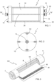
- FIGS 1 to 6 show a membrane arrangement 1 for treating a fluid according to the invention.
- the membrane arrangement 1 of the invention is conceived for treatment of a fluid, in particular liquids.
- the fluid to be treated is water.
- the membrane arrangement 1 of the invention comprises a membrane module 100 comprising a glass fibre membrane shell 2.
- the membrane shell 2 extends in a longitudinal direction L of the module with an inlet end and an outlet end.
- the membrane module 100 of this example is the model TW30HP-4611 of the company Toray.
- This exemplary module 100 is a cylindrical module of 28.78 cm length and has a 11.7 cm diameter.
- the invention is not limited to this type of membrane module.
- other more widespread membrane modules 100 sizes can also be applied in the invention.
- the most popular and standard RO membrane modules 10 are 100 cm long and 6 to 40 cm of diameter including a central permeate duct of 1.5 to 3 cm of inner diameter.
- FIG. 3 shows a schematic constructional example of this kind of membrane modules 100.
- the membrane module 100 comprises following main parts: an outer membrane shell 2, an inlet end flange 4, and outlet end flange 6 and a permeate collecting duct 8 and a membrane element 20 attached to the latter.
- This membrane element 20 is a spiral-wound membrane element 20.
- the membrane element 20 is made up of a plurality of membrane sheets 46 connected to a permeate duct 8, these membrane sheets 46 being separated by a laminar web like channel spacer 48.
- the membrane element 20 applicable to the membrane arrangement 1 of the invention is one of the group consisting in a RO membrane, a NF membrane, an UF membrane or a MF membrane.
- the inlet end flange 4 is arranged on the inlet end of the membrane shell 2, while the outlet end flange 6 is arranged on the outlet end of the membrane shell 2.
- the permeate collecting duct 8 extends along the membrane module 100 between said inlet and said outlet end flanges 4, 6. Indeed, the collecting duct 8 protrudes from the centre of the inlet and outlet end flanges 4, 6.
- the collecting duct 8 comprises a plurality of perforations 50 for being in fluid communication with the membrane shell 2.
- the perforations 50 are shown in a larger scale for illustrative purposes. Thanks to the perforations 50 on the collecting duct 8, during the operation of the membrane arrangement 1 in filtration mode, the permeate is collected when it flows from the membrane sheets 46 of the membrane element 20 and the collecting duct 8 allows the permeate to flow out through said collecting duct 8.
- the membrane arrangement 1 further comprises an inlet cap 10 and an outlet cap 14. These two parts are preferably made of a plastic material such as polyvinyl chloride (PVC), polyamide 6 (PA6), polyamide 66 (PA66) with glass fibre or polypropylene (PP). This makes these parts economic and easy to produce.
- PVC polyvinyl chloride
- PA6 polyamide 6
- PA66 polyamide 66
- PP polypropylene
- the inlet cap 10 comprises one inlet opening 12. It is arranged in fluid communication with the inlet end of the membrane module 100 for introducing through the inlet opening 12 the feed stream of influent into the membrane arrangement 1. More particularly, in this embodiment the inlet cap 10 is sealingly arranged on the inlet end flange 4 of the membrane module 100. In figure 4 , it is apparent that in order to feed the membrane module 100, the inlet cap 10 is in fluid communication with the membrane module 100. Thanks to the fact that the collecting duct 8 is sealed at the inlet end, the influent, after crossing the inlet cap 10, is directed to membrane element 20.
- the outlet cap 14 comprises a first outlet opening 16 and a second outlet opening 18, the outlet cap being arranged in fluid communication with the outlet end of the membrane module 100.
- the first outlet opening 16 is connected to the permeate collecting duct 8 for allowing a permeate stream to flow out from the membrane module 100 through the first outlet opening 16 when the membrane arrangement works in filtration mode.
- the second outlet opening 18 allows a concentrate stream to flow out from said membrane module 100 in case the membrane needs to be washed.
- the outlet cap 14 is sealingly arranged on the outlet end flange 6 of the membrane module 100.
- the membrane arrangement 1 further comprises four elongated connecting members 34 with fastening means 52 for connecting the inlet and outlet caps 10, 14 together in an assembly position.
- these elongated connecting members are rigid rods, and specially preferably are stainless steel rods.
- the fastening means 52 are butterfly hand twist nuts tighten on a threaded section provided at the end of the connecting members 34.
- Other fastening means are also possible, such as fast tightening clamps, conventional nuts or the like.
- the elongated connecting members could be in form of tightening straps, such as nylon straps with the corresponding fastening clamps.
- the inlet and outlet caps 10, 14 are sealingly arranged on the membrane module 100.
- the membrane arrangement 1 comprises an outer housing that is not an additional part as it is the case of the pressure vessels known in the art. Instead, according to the invention the outer housing is the membrane shell 2. This provides a very simple and economical arrangement, which is easy to produce, transport and assemble.
- the inlet and outlet caps 10, 14 comprise respectively an inner side 22 and an outer side 24.
- the inner sides 22 respectively comprise one annular recess 26.
- the membrane arrangement 1 further comprises an inlet sealing member 28 and an outlet sealing member 30.
- the inlet and outlet sealing members 28, 30 are respectively dimensioned and arranged in the annular recesses 26 for providing the sealing engagement with the respective front side 32 of said membrane module 100. Therefore, the sealing members are in this case a rubber O-ring with circular cross-section working in the axial direction compressed between the corresponding inlet or outlet caps 10, 14 and the inlet and outlet flanges 4, 6.
- sealing members 28, 30 are arranged in a radial annular recess 42. In this case, the sealing engagement would then take place by the radial compression of the sealing members 28, 30 between the inlet and outlet flanges 4, 6 and a cylindrical crown 44 of the corresponding inlet and outlet caps 10, 14.
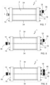
- FIG. 7 shows an embodiment in which the membrane arrangement 1 can be used in gravity-driven filtering mode.
- the membrane arrangement comprises a second sealing plug which is configured to be inserted in a sealing manner in the second outlet opening 18 of the outlet cap 14.
- the influent is introduced in the membrane arrangement 1 through the inlet opening 12 and after entering the membrane module 100 the permeate flows out the first outlet opening 16.
- FIG 8 shows an embodiment in the membrane arrangement 1 for membrane module recycling of any kind.
- the membrane arrangement 1 further comprises a first and a second sealing plugs 36, 38.
- the first and second sealing plugs 36, 38 are configured to be inserted in a sealing manner respectively in the inlet opening 12 of the inlet cap 10 and in the second outlet opening 18 of the outlet cap 14. Initially, only the second sealing plug is inserted. Then the membrane arrangement 1 filled up with an etching solution such as a sodium hypochlorite solution during a predetermined period of time, until the polyamide layer of the spiral-wound membrane has been partially or totally removed and the membrane element 20 has been modified into an NF or UF membrane element, respectively.
- an etching solution such as a sodium hypochlorite solution
- Figure 9 shows a third arrangement which, additionally to the already mentioned first and second sealing plugs 36, 38, it further comprises a third sealing plug 40.
- This third sealing plug 40 is also configured to be inserted in a sealing manner in the first outlet opening 16 of the outlet cap 14.
- the arrangement is conceived for membrane preservation and, in particular, for membrane preservation when the membrane element 20 is a RO membrane, NF membrane, an UF membrane or a MF membrane.
- Figure 10 shows an alternative solution for the elongated connecting members.
- the elongated connecting members 34 are flexible under compression and rigid under tension, since they are fastening straps comprising a ratchet as fastening means 52.
- This solution is very practical for emergency applications.
- the fastening straps are easy to transport and inexpensive.
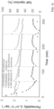
- a pilot-scale gravity driven membrane (GDM) system 200 was setup to use the membrane modules 100 in two distinct configurations as shown in Figure 11 :
- NF-like and UF-like membrane modules refer to membrane modules recycled from a RO membrane module.
- the membrane arrangement 1 performance was tested filtering MilliQ ® water of the company Merck KGaA operating in both configurations: submerged and external. In both cases, it was observed that the use of the inlet and outlet caps 10, 14 prevent air ingress into the membrane arrangement 1. Therefore, the permeability maintained constant at any hydraulic pressure. This is particularly interesting in the submerged configuration when the membrane arrangement 1 was not fully covered by water. Additionally, the highest membrane permeability (see following table 1) was observed when the membrane arrangement 1 operated horizontally out of the water tank and closest to the floor. Table 1. Membrane permeability working out of the tank and placed horizontally. Permeability (L m -2 h -1 bar -1 ) NF-like 8.00 ⁇ 0 08 UF-like 19.32 ⁇ 0.34
- a synthetic water (simulating river quality) with total organic dissolved carbon lower than 6.5 ppm was used to address the limitation of the system to separate salts and organic compounds.
- the water solution contained: humic acid, which is a typical model organic foulant widely used; protein (bovine serum albumin, BSA), alginate acid (only for UF-like membrane), which together with divalent cations accelerates fouling; diatomaceous earth, which gives suspended solid (only for UF-like membranes), and salts (400 mg/L NaCl and 80 mg/L MgSO 4 at any time).
- the membrane arrangement 1 was operating in submerged and external configuration.
- the main outcomes of these experiments were the following:
- Table 2 shows the rejection coefficients for NF-like and UF-like membrane modules 20.
- NF-like membranes the effect of concentration polarization caused a reduction of permeability and rejection coefficients over time ( ⁇ 10% rejection coefficients after 80 min) when operating in a continuous mode.
- flushing after the relaxing time (40 min). Flushing favoured a higher and constant permeability and improved the salt rejection coefficient by approximately 10%. Note that applying flushing is possible thanks to the invention.
- Table 3 shows the percentage of the permeability lost in case of NF-like membrane. The highest lost was observed after being filtering synthetic water (15.3% of permeability reduction comparing with the MilliQ ® permeability before the membrane was filtering organic compounds). The cleaning procedures were carried out following the ascendant sequence (from 1 to 4). In all the cases the cleaning procedures restored the membrane permeability between 90-94%, even after CEB. Therefore, some irreversible fouling remained over the membrane. Table 3.
- the membrane arrangement 1 according to the invention with a UF-like membrane element 20 was set up in a submerged configuration.
- the membrane arrangement 1 was submerged in a 70 L tank and operated in discontinue mode, refilling 1-2 times the tank per day, for 7 days.
- the membrane module 100 was maintained in water overnight. The following day, water was flushed using the concentrate stream and renewed with fresh water. Feed water was collected from a fresh shadow well. Water has 6.8 pH, ⁇ 500 cm/Ms, ⁇ 5NTU and around 200 CFU/100 mL of coliforms bacteria. The estimated transmembrane pressure was ⁇ 0.16 bar.
- a cross flow system membrane arrangement 1 has an inlet stream through the inlet opening 12 and two outlet streams, through the first and second outlet openings 16, 18: permeate, which is the clean water and concentrate effluent) in a total recycled mode (turning back the permeate to the feed tank) was used.
- the object of the experiment was to test the material resistance under cross flow pressurized condition.
- the membrane arrangement of the invention provides a very reliable, inexpensive and yet simple solution for treating liquids of all kinds and especially for treating water.
Landscapes
- Chemical & Material Sciences (AREA)
- Chemical Kinetics & Catalysis (AREA)
- Separation Using Semi-Permeable Membranes (AREA)
- Filling Or Discharging Of Gas Storage Vessels (AREA)
- Auxiliary Devices For And Details Of Packaging Control (AREA)
- Electrotherapy Devices (AREA)
Claims (11)
- Membrananordnung (1) zum Behandeln eines Fluids, umfassend:[a] ein Membranmodul (100) umfassend eine sich in einer Längsrichtung (L) erstreckende Membranhülle (2) mit einem Einlassende und einem Auslassende, wobei die Membranhülle (2) ein Membranelement (20) enthält, wobei das Membranelement (20) des Membranmoduls (100) ein spiralförmig gewickeltes Membranelement ist und die Membran des Membranelements (20) eine Membran aus der Gruppe bestehend aus einer Umkehrosmosemembran, einer Nanofiltrationsmembran, einer Ultrafiltrationsmembran oder einer Mikrofiltrationsmembran ist,wobei das Membranmodul (100) ferner umfasst:[b] einen Einlassende-Flansch (4), der an dem Einlassende der Membranhülle (2) angeordnet ist;[c] einen Auslassende-Flansch (6), der an dem Auslassende der Membranhülle (2) angeordnet ist; und[d] einen Permeatsammelkanal (8), wobei sich der Sammelkanal (8) entlang des Membranmoduls (100) zwischen dem Einlass- und dem Auslassende-Flansch (4, 6) erstreckt und mit der Membranhülle (2) in Fluidverbindung steht, um das Permeat zu sammeln, das während des Betriebs der Membrananordnung (100) aus dem Membranelement (20) fließt, und zu ermöglichen, dass das Permeat durch den Sammelkanal (8) herausfließt,wobei die Membrananordnung (1) ferner umfasst:[e] eine Einlasskappe (10) umfassend eine Einlassöffnung (12), wobei die Einlasskappe (10) in Fluidverbindung mit dem Einlassende des Membranmoduls (100) angeordnet ist, um einen Zuführstrom von Zufluss durch die Einlassöffnung (12) in die Membrananordnung (1) einzuleiten;[f] eine Auslasskappe (14) umfassend mindestens eine erste Auslassöffnung (16), wobei die Auslasskappe (14) in Fluidverbindung mit dem Auslassende des Membranmoduls (100) angeordnet ist, um zu ermöglichen, dass ein Permeatstrom durch die mindestens eine erste Auslassöffnung (16) aus dem Membranmodul (100) herausfließt;[g] eine Mehrzahl einzelner länglicher Verbindungselemente (34) mit Befestigungsmitteln (52) zum Verbinden der Einlass- und der Auslasskappe (10, 14) miteinander in einer Montageposition,[h] wobei die Einlass- und die Auslasskappe (10, 14) dichtend auf dem Membranmodul (100) angeordnet sind,[i] wobei die Einlasskappe (10) dichtend auf dem Einlassende-Flansch (4) des Membranmoduls (100) und in Fluidverbindung damit angeordnet ist, um den Zuführstrom von Zufluss in die Membrananordnung (1) einzuleiten, und[j] wobei die Auslasskappe (14) ferner eine zweite Auslassöffnung (18) umfasst, wobei die Auslasskappe (14) dichtend auf dem Auslassende-Flansch (6) des Membranmoduls (100) und in Fluidverbindung damit angeordnet ist, derart dass die erste Auslassöffnung (16) mit dem Permeatsammelkanal (8) verbunden ist, um zu ermöglichen, dass ein Permeatstrom durch die mindestens erste Auslassöffnung (16) aus dem Membranmodul (100) herausfließt, während die zweite Auslassöffnung (18) ermöglicht, dass ein Konzentratstrom aus dem Membranmodul (100) herausfließt,dadurch gekennzeichnet, dass[k] die Membranhülle (2) das äußere Gehäuse der Membrananordnung ist.
- Membrananordnung (1) nach Anspruch 1, dadurch gekennzeichnet, dass die Einlass- und die Auslasskappe (10, 14) jeweils eine Innenseite (22) und eine Außenseite (24) umfassen, wobei die Innenseiten (22) jeweils mindestens eine ringförmige Vertiefung (26) aufweisen, wobei die Membrananordnung (1) ferner ein Einlassdichtungselement (28) und ein Auslassdichtungselement (30) umfassen, und dadurch, dass das Einlass- und das Auslassdichtungselement (28, 30) jeweils dimensioniert und in den ringförmigen Vertiefungen (26) angeordnet sind, um einen Dichtungseingriff mit der jeweiligen Vorderseite (32) des Membranmoduls (100) bereitzustellen.
- Membrananordnung (1) nach einem der Ansprüche 1 oder 2, dadurch gekennzeichnet, dass sie ferner einen ersten und einen zweiten Dichtungsstopfen (36, 38) umfasst, wobei der erste und der zweite Dichtungsstopfen (36, 38) dazu konfiguriert sind, um auf eine abdichtende Weise in die Einlassöffnung (12) der Einlasskappe (10) bzw. in die zweite Auslassöffnung (18) der Auslasskappe (14) eingesetzt zu werden.
- Membrananordnung (1) nach einem der Ansprüche 2 oder 3, dadurch gekennzeichnet, dass sie ferner einen dritten Dichtungsstopfen (40) umfasst, wobei der dritte Dichtungsstopfen (40) dazu konfiguriert ist, um auf eine abdichtende Weise in die erste Auslassöffnung (16) der Auslasskappe (14) eingesetzt zu werden.
- Membrananordnung (1) nach einem der Ansprüche 1 bis 4, dadurch gekennzeichnet, dass die länglichen Verbindungselemente (34) der Mehrzahl von Verbindungselementen (34) starr sind.
- Membrananordnung (1) nach Anspruch 5, dadurch gekennzeichnet, dass die länglichen Verbindungselemente (34) Längsstäbe sind.
- Membrananordnung (1) nach einem der Ansprüche 1 bis 4, dadurch gekennzeichnet, dass die länglichen Verbindungselemente (34) der Mehrzahl von Verbindungselementen (34) unter Druck flexibel und unter Spannung starr sind.
- Membrananordnung (1) nach Anspruch 7, dadurch gekennzeichnet, dass die länglichen Verbindungselemente (34) Befestigungsbänder sind.
- Verfahren zum Zusammensetzen einer Membrananordnung (1), umfassend die Schritte:[a] Bereitstellen eines Membranmoduls (100) umfassend eine Membranhülle (2), die sich in einer Längsrichtung (L) erstreckt, mit einem Einlassende und einem Auslassende, wobei die Membranhülle (2) ein Membranelement (20) enthält, wobei das Membranelement (20) des Membranmoduls (100) ein spiralförmig gewickeltes Membranelement ist und die Membran des Membranelements (20) eine Membran aus der Gruppe bestehend aus einer Umkehrosmosemembran, einer Nanofiltrationsmembran, einer Ultrafiltrationsmembran oder einer Mikrofiltrationsmembran ist,wobei das Membranmodul (100) ferner aufweist:[b] einen Einlassende-Flansch (4), der an dem Einlassende der Membranhülle (2) angeordnet ist;[c] einen Auslassende-Flansch (6), der an dem Auslassende der Membranhülle (2) angeordnet ist; und[d] einen Permeatsammelkanal (8), wobei sich der Sammelkanal (8) entlang des Membranmoduls (100) zwischen dem Einlass- und dem Auslassende-Flansch (4, 6) erstreckt und mit der Membranhülle (2) in Fluidverbindung steht, um das Permeat zu sammeln, das während des Betriebs der Membrananordnung (100) aus dem Membranelement (20) fließt, und um zu ermöglichen, dass das Permeat durch den Sammelkanal (8) herausfließt,wobei das Verfahren ferner die Schritte umfasst:[e] Bereitstellen einer Einlasskappe (10) umfassend eine Einlassöffnung (12);[f] Anordnen der Einlasskappe (10) in Fluidverbindung mit dem Einlassende des Membranmoduls (100) zum Einleiten eines Zuführstroms von Zufluss durch die Einlassöffnung (12) in die Membrananordnung (1);[g] Bereitstellen einer Auslasskappe (14), die mindestens eine erste Auslassöffnung (16) umfasst;[h] Anordnen der Auslasskappe (14) in Fluidverbindung mit dem Auslassende des Membranmoduls (100), um zu ermöglichen, dass ein Permeatstrom durch die mindestens eine erste Auslassöffnung (16) aus dem Membranmodul (100) herausfließt;[i] Bereitstellen einer Mehrzahl einzelner länglicher Verbindungselemente (34) mit Befestigungsmitteln (52) zum Verbinden der Einlass- und der Auslasskappe (10, 14) in einer Montageposition;[j] Verbinden der Einlass- und der Auslasskappe (10, 14) miteinander in einer Montageposition mittels der einzelnen länglichen Verbindungselemente (34) und der Befestigungsmittel (52); und[k] Anordnen der Einlass- und der Auslasskappe (10, 14) auf dem Membranmodul (100) auf eine abdichtende Weise,[I] abdichtendes Anordnen der Einlasskappe (10) auf dem Einlassende-Flansch (4) des Membranmoduls (100) und in Fluidverbindung damit zum Einleiten des Zuführstroms von Zufluss in die Membrananordnung (1),[m] wobei die Auslasskappe (14) ferner eine zweite Auslassöffnung (18) aufweist, derart dass die Auslasskappe (14) abdichtend auf dem Auslassende-Flansch (6) des Membranmoduls (100) und in Fluidverbindung damit angeordnet ist, derart dass die erste Auslassöffnung (16) mit dem Permeatsammelkanal (8) verbunden ist, um zu ermöglichen, dass ein Permeatstrom durch die mindestens erste Auslassöffnung (16) aus dem Membranmodul (100) herausfließt, während die zweite Auslassöffnung (18) ermöglicht, dass ein Konzentratstrom aus dem Membranmodul (100) herausfließt,dadurch gekennzeichnet, dass es ferner die Schritte umfasst:[o] Verwenden der Membranhülle (2) als das Außengehäuse der Membrananordnung (100).
- Verfahren nach Anspruch 9, dadurch gekennzeichnet, dassdie Einlass- und die Auslasskappe (10, 14) jeweils eine Innenseite (22) und eine Außenseite (24) umfassen, wobei die Innenseiten (22) jeweils mindestens eine ringförmige Vertiefung (26) umfassen, wobei die Membrananordnung (1) ferner ein Einlassdichtungselement (28) und ein Auslassdichtungselement (30) umfasst; unddadurch, dass das Verfahren ferner den Schritt Anordnen des Einlass- und des Auslassdichtungselements (28, 30) in den ringförmigen Vertiefungen (26), um einen Dichtungseingriff mit der jeweiligen Vorderseite (32) des Membranmoduls (100) bereitzustellen, umfasst.
- Verwendung einer Membrananordnung (1) nach einem der Ansprüche 1 bis 8 in schwerkraftbetriebenem Filtermodus.
Priority Applications (4)
| Application Number | Priority Date | Filing Date | Title |
|---|---|---|---|
| ES20382065T ES3015722T3 (en) | 2020-01-31 | 2020-01-31 | Membrane arrangement and corresponding assembly method |
| EP20382065.9A EP3858470B1 (de) | 2020-01-31 | 2020-01-31 | Membrananordnung und entsprechendes montageverfahren |
| AU2021213930A AU2021213930B2 (en) | 2020-01-31 | 2021-01-31 | Membrane arrangement and corresponding assembly method |
| PCT/EP2021/052228 WO2021152162A1 (en) | 2020-01-31 | 2021-01-31 | Membrane arrangement and corresponding assembly method |
Applications Claiming Priority (1)
| Application Number | Priority Date | Filing Date | Title |
|---|---|---|---|
| EP20382065.9A EP3858470B1 (de) | 2020-01-31 | 2020-01-31 | Membrananordnung und entsprechendes montageverfahren |
Publications (3)
| Publication Number | Publication Date |
|---|---|
| EP3858470A1 EP3858470A1 (de) | 2021-08-04 |
| EP3858470B1 true EP3858470B1 (de) | 2025-01-22 |
| EP3858470C0 EP3858470C0 (de) | 2025-01-22 |
Family
ID=69726533
Family Applications (1)
| Application Number | Title | Priority Date | Filing Date |
|---|---|---|---|
| EP20382065.9A Active EP3858470B1 (de) | 2020-01-31 | 2020-01-31 | Membrananordnung und entsprechendes montageverfahren |
Country Status (4)
| Country | Link |
|---|---|
| EP (1) | EP3858470B1 (de) |
| AU (1) | AU2021213930B2 (de) |
| ES (1) | ES3015722T3 (de) |
| WO (1) | WO2021152162A1 (de) |
Families Citing this family (1)
| Publication number | Priority date | Publication date | Assignee | Title |
|---|---|---|---|---|
| DE102022128233A1 (de) * | 2022-10-25 | 2024-04-25 | R.T.S. Rochem Technical Services GmbH | Filtervorrichtung ohne Spannbolzen |
Family Cites Families (7)
| Publication number | Priority date | Publication date | Assignee | Title |
|---|---|---|---|---|
| DE10224634C2 (de) * | 2002-06-04 | 2003-07-31 | Kamat Pumpen Gmbh & Co Kg | Vorrichtung zum Filtern von unter einem hohen Druck geförderten Fluiden |
| US20090223891A1 (en) * | 2008-03-06 | 2009-09-10 | Ray Gauthier | System, device and method for on-site wastewater processing |
| ATE542594T1 (de) | 2008-04-08 | 2012-02-15 | Knappe Holger | Modulare membrangehäuseelemente und verfahren zu deren herstellung |
| CN105854615B (zh) * | 2016-06-03 | 2019-04-16 | 成都美富特膜环保科技有限公司 | 膜过滤组件及其膜芯预紧结构 |
| ES2589151B1 (es) | 2016-07-08 | 2017-10-19 | Valoriza Agua S.L | Proceso de transformación de membranas de poliamida con enrollamiento en espiral que han agotado su vida útil en membranas de utilidad industrial |
| CN206652394U (zh) | 2017-04-21 | 2017-11-21 | 江苏坤奕环境工程有限公司 | 超高压开放式流道网管式高压反渗透膜组件 |
| CN109574149B (zh) | 2018-12-29 | 2022-04-26 | 江苏坤奕环境技术股份有限公司 | 一种超高压开放式流道碟管式反渗透膜组件 |
-
2020
- 2020-01-31 EP EP20382065.9A patent/EP3858470B1/de active Active
- 2020-01-31 ES ES20382065T patent/ES3015722T3/es active Active
-
2021
- 2021-01-31 WO PCT/EP2021/052228 patent/WO2021152162A1/en not_active Ceased
- 2021-01-31 AU AU2021213930A patent/AU2021213930B2/en active Active
Also Published As
| Publication number | Publication date |
|---|---|
| EP3858470C0 (de) | 2025-01-22 |
| ES3015722T3 (en) | 2025-05-07 |
| AU2021213930A1 (en) | 2022-06-30 |
| WO2021152162A1 (en) | 2021-08-05 |
| AU2021213930B2 (en) | 2026-04-23 |
| EP3858470A1 (de) | 2021-08-04 |
Similar Documents
| Publication | Publication Date | Title |
|---|---|---|
| AU2022200930B2 (en) | Water purification systems and methods having pressurized draw stream | |
| US7410581B2 (en) | Branched flow filtration and system | |
| US20110168381A1 (en) | Osmotic Water Transfer System and Related Processes | |
| US5112483A (en) | Slow sand/nanofiltration water treatment system | |
| CN110536742B (zh) | 高回收率集成uf/ro系统 | |
| EP2703066A1 (de) | Verfahren zur reinigung eines membranmoduls | |
| US5234583A (en) | Semi-permeable membrane filtering systems for swimming pools | |
| JP2000271460A (ja) | スパイラル型膜モジュールを用いた処理システムおよび処理方法 | |
| US20130264285A1 (en) | Process and facility to treat contaminated process water | |
| US20150144560A1 (en) | Separation membrane unit and method for using the same to produce fresh water | |
| EP2633898A1 (de) | Hohlfasermembran-filtrationsvorrichtung und verfahren zum waschen von hohlfasermembranmodulen | |
| WO2003033122A2 (en) | Apparatus for fluid purification and methods of manufacture and use thereof | |
| JP6191464B2 (ja) | 除濁膜モジュールの運転方法 | |
| AU2021213930B2 (en) | Membrane arrangement and corresponding assembly method | |
| WO2016181942A1 (ja) | 車載型造水装置 | |
| JPH11137974A (ja) | スパイラル型膜エレメント | |
| Nishimura et al. | Reverse osmosis | |
| JP2002028453A (ja) | スパイラル型膜エレメントおよびスパイラル型膜モジュールの運転方法および洗浄方法 | |
| Jurmu | Effect of prefiltration on natural organic matter removal by nanofiltration in drinking water treatment | |
| CN112774442A (zh) | 一种自清洁反渗透膜及其制备方法 | |
| Jurmu | of thesis Effect of pretreatment on natural organic matter removal by nanofiltration in | |
| Poutanen | Janne Jurmu | |
| Abd Alameer | Supervisor Certification | |
| JPH10230138A (ja) | スパイラル型膜エレメント |
Legal Events
| Date | Code | Title | Description |
|---|---|---|---|
| PUAI | Public reference made under article 153(3) epc to a published international application that has entered the european phase |
Free format text: ORIGINAL CODE: 0009012 |
|
| STAA | Information on the status of an ep patent application or granted ep patent |
Free format text: STATUS: THE APPLICATION HAS BEEN PUBLISHED |
|
| AK | Designated contracting states |
Kind code of ref document: A1 Designated state(s): AL AT BE BG CH CY CZ DE DK EE ES FI FR GB GR HR HU IE IS IT LI LT LU LV MC MK MT NL NO PL PT RO RS SE SI SK SM TR |
|
| STAA | Information on the status of an ep patent application or granted ep patent |
Free format text: STATUS: REQUEST FOR EXAMINATION WAS MADE |
|
| 17P | Request for examination filed |
Effective date: 20220204 |
|
| RBV | Designated contracting states (corrected) |
Designated state(s): AL AT BE BG CH CY CZ DE DK EE ES FI FR GB GR HR HU IE IS IT LI LT LU LV MC MK MT NL NO PL PT RO RS SE SI SK SM TR |
|
| GRAP | Despatch of communication of intention to grant a patent |
Free format text: ORIGINAL CODE: EPIDOSNIGR1 |
|
| STAA | Information on the status of an ep patent application or granted ep patent |
Free format text: STATUS: GRANT OF PATENT IS INTENDED |
|
| INTG | Intention to grant announced |
Effective date: 20240830 |
|
| GRAS | Grant fee paid |
Free format text: ORIGINAL CODE: EPIDOSNIGR3 |
|
| GRAA | (expected) grant |
Free format text: ORIGINAL CODE: 0009210 |
|
| STAA | Information on the status of an ep patent application or granted ep patent |
Free format text: STATUS: THE PATENT HAS BEEN GRANTED |
|
| AK | Designated contracting states |
Kind code of ref document: B1 Designated state(s): AL AT BE BG CH CY CZ DE DK EE ES FI FR GB GR HR HU IE IS IT LI LT LU LV MC MK MT NL NO PL PT RO RS SE SI SK SM TR |
|
| REG | Reference to a national code |
Ref country code: GB Ref legal event code: FG4D |
|
| REG | Reference to a national code |
Ref country code: CH Ref legal event code: EP |
|
| REG | Reference to a national code |
Ref country code: IE Ref legal event code: FG4D |
|
| REG | Reference to a national code |
Ref country code: DE Ref legal event code: R096 Ref document number: 602020045099 Country of ref document: DE |
|
| U01 | Request for unitary effect filed |
Effective date: 20250207 |
|
| U07 | Unitary effect registered |
Designated state(s): AT BE BG DE DK EE FI FR IT LT LU LV MT NL PT RO SE SI Effective date: 20250213 |
|
| U20 | Renewal fee for the european patent with unitary effect paid |
Year of fee payment: 6 Effective date: 20250225 |
|
| PG25 | Lapsed in a contracting state [announced via postgrant information from national office to epo] |
Ref country code: RS Free format text: LAPSE BECAUSE OF FAILURE TO SUBMIT A TRANSLATION OF THE DESCRIPTION OR TO PAY THE FEE WITHIN THE PRESCRIBED TIME-LIMIT Effective date: 20250422 |
|
| PG25 | Lapsed in a contracting state [announced via postgrant information from national office to epo] |
Ref country code: PL Free format text: LAPSE BECAUSE OF FAILURE TO SUBMIT A TRANSLATION OF THE DESCRIPTION OR TO PAY THE FEE WITHIN THE PRESCRIBED TIME-LIMIT Effective date: 20250122 |
|
| PG25 | Lapsed in a contracting state [announced via postgrant information from national office to epo] |
Ref country code: NO Free format text: LAPSE BECAUSE OF FAILURE TO SUBMIT A TRANSLATION OF THE DESCRIPTION OR TO PAY THE FEE WITHIN THE PRESCRIBED TIME-LIMIT Effective date: 20250422 Ref country code: IS Free format text: LAPSE BECAUSE OF FAILURE TO SUBMIT A TRANSLATION OF THE DESCRIPTION OR TO PAY THE FEE WITHIN THE PRESCRIBED TIME-LIMIT Effective date: 20250522 |
|
| PG25 | Lapsed in a contracting state [announced via postgrant information from national office to epo] |
Ref country code: HR Free format text: LAPSE BECAUSE OF FAILURE TO SUBMIT A TRANSLATION OF THE DESCRIPTION OR TO PAY THE FEE WITHIN THE PRESCRIBED TIME-LIMIT Effective date: 20250122 |
|
| PG25 | Lapsed in a contracting state [announced via postgrant information from national office to epo] |
Ref country code: GR Free format text: LAPSE BECAUSE OF FAILURE TO SUBMIT A TRANSLATION OF THE DESCRIPTION OR TO PAY THE FEE WITHIN THE PRESCRIBED TIME-LIMIT Effective date: 20250423 |
|
| REG | Reference to a national code |
Ref country code: CH Ref legal event code: PL |
|
| PG25 | Lapsed in a contracting state [announced via postgrant information from national office to epo] |
Ref country code: SM Free format text: LAPSE BECAUSE OF FAILURE TO SUBMIT A TRANSLATION OF THE DESCRIPTION OR TO PAY THE FEE WITHIN THE PRESCRIBED TIME-LIMIT Effective date: 20250122 |
|
| PG25 | Lapsed in a contracting state [announced via postgrant information from national office to epo] |
Ref country code: MC Free format text: LAPSE BECAUSE OF FAILURE TO SUBMIT A TRANSLATION OF THE DESCRIPTION OR TO PAY THE FEE WITHIN THE PRESCRIBED TIME-LIMIT Effective date: 20250122 |
|
| PG25 | Lapsed in a contracting state [announced via postgrant information from national office to epo] |
Ref country code: CH Free format text: LAPSE BECAUSE OF NON-PAYMENT OF DUE FEES Effective date: 20250131 |
|
| PG25 | Lapsed in a contracting state [announced via postgrant information from national office to epo] |
Ref country code: CZ Free format text: LAPSE BECAUSE OF FAILURE TO SUBMIT A TRANSLATION OF THE DESCRIPTION OR TO PAY THE FEE WITHIN THE PRESCRIBED TIME-LIMIT Effective date: 20250122 |
|
| PG25 | Lapsed in a contracting state [announced via postgrant information from national office to epo] |
Ref country code: SK Free format text: LAPSE BECAUSE OF FAILURE TO SUBMIT A TRANSLATION OF THE DESCRIPTION OR TO PAY THE FEE WITHIN THE PRESCRIBED TIME-LIMIT Effective date: 20250122 |
|
| PLBE | No opposition filed within time limit |
Free format text: ORIGINAL CODE: 0009261 |
|
| STAA | Information on the status of an ep patent application or granted ep patent |
Free format text: STATUS: NO OPPOSITION FILED WITHIN TIME LIMIT |
|
| U20 | Renewal fee for the european patent with unitary effect paid |
Year of fee payment: 7 Effective date: 20251104 |
|
| GBPC | Gb: european patent ceased through non-payment of renewal fee |
Effective date: 20250422 |
|
| 26N | No opposition filed |
Effective date: 20251023 |
|
| PG25 | Lapsed in a contracting state [announced via postgrant information from national office to epo] |
Ref country code: GB Free format text: LAPSE BECAUSE OF NON-PAYMENT OF DUE FEES Effective date: 20250422 |
|
| PG25 | Lapsed in a contracting state [announced via postgrant information from national office to epo] |
Ref country code: IE Free format text: LAPSE BECAUSE OF NON-PAYMENT OF DUE FEES Effective date: 20250131 |
|
| PGFP | Annual fee paid to national office [announced via postgrant information from national office to epo] |
Ref country code: ES Payment date: 20260202 Year of fee payment: 7 |