EP3858509B1 - Procédé et ensemble de formation d'un objet annulaire - Google Patents
Procédé et ensemble de formation d'un objet annulaire Download PDFInfo
- Publication number
- EP3858509B1 EP3858509B1 EP21154412.7A EP21154412A EP3858509B1 EP 3858509 B1 EP3858509 B1 EP 3858509B1 EP 21154412 A EP21154412 A EP 21154412A EP 3858509 B1 EP3858509 B1 EP 3858509B1
- Authority
- EP
- European Patent Office
- Prior art keywords
- die
- preform
- angle
- clamp
- clamp member
- Prior art date
- Legal status (The legal status is an assumption and is not a legal conclusion. Google has not performed a legal analysis and makes no representation as to the accuracy of the status listed.)
- Active
Links
Images





Classifications
-
- B—PERFORMING OPERATIONS; TRANSPORTING
- B21—MECHANICAL METAL-WORKING WITHOUT ESSENTIALLY REMOVING MATERIAL; PUNCHING METAL
- B21D—WORKING OR PROCESSING OF SHEET METAL OR METAL TUBES, RODS OR PROFILES WITHOUT ESSENTIALLY REMOVING MATERIAL; PUNCHING METAL
- B21D22/00—Shaping without cutting, by stamping, spinning, or deep-drawing
- B21D22/02—Stamping using rigid devices or tools
- B21D22/06—Stamping using rigid devices or tools having relatively-movable die parts
-
- B—PERFORMING OPERATIONS; TRANSPORTING
- B21—MECHANICAL METAL-WORKING WITHOUT ESSENTIALLY REMOVING MATERIAL; PUNCHING METAL
- B21D—WORKING OR PROCESSING OF SHEET METAL OR METAL TUBES, RODS OR PROFILES WITHOUT ESSENTIALLY REMOVING MATERIAL; PUNCHING METAL
- B21D22/00—Shaping without cutting, by stamping, spinning, or deep-drawing
- B21D22/20—Deep-drawing
- B21D22/22—Deep-drawing with devices for holding the edge of the blanks
-
- B—PERFORMING OPERATIONS; TRANSPORTING
- B21—MECHANICAL METAL-WORKING WITHOUT ESSENTIALLY REMOVING MATERIAL; PUNCHING METAL
- B21D—WORKING OR PROCESSING OF SHEET METAL OR METAL TUBES, RODS OR PROFILES WITHOUT ESSENTIALLY REMOVING MATERIAL; PUNCHING METAL
- B21D22/00—Shaping without cutting, by stamping, spinning, or deep-drawing
- B21D22/20—Deep-drawing
- B21D22/24—Deep-drawing involving two drawing operations having effects in opposite directions with respect to the blank
-
- B—PERFORMING OPERATIONS; TRANSPORTING
- B21—MECHANICAL METAL-WORKING WITHOUT ESSENTIALLY REMOVING MATERIAL; PUNCHING METAL
- B21D—WORKING OR PROCESSING OF SHEET METAL OR METAL TUBES, RODS OR PROFILES WITHOUT ESSENTIALLY REMOVING MATERIAL; PUNCHING METAL
- B21D25/00—Working sheet metal of limited length by stretching, e.g. for straightening
- B21D25/02—Working sheet metal of limited length by stretching, e.g. for straightening by pulling over a die
-
- B—PERFORMING OPERATIONS; TRANSPORTING
- B21—MECHANICAL METAL-WORKING WITHOUT ESSENTIALLY REMOVING MATERIAL; PUNCHING METAL
- B21D—WORKING OR PROCESSING OF SHEET METAL OR METAL TUBES, RODS OR PROFILES WITHOUT ESSENTIALLY REMOVING MATERIAL; PUNCHING METAL
- B21D53/00—Making other particular articles
- B21D53/92—Making other particular articles other parts for aircraft
Definitions
- This disclosure relates generally to methods and assemblies for forming an annular object.
- a modern aircraft propulsion system for an airplane such as a commercial airliner includes a nacelle for housing a gas turbine engine.
- the nacelle typically includes an inlet lip (e.g., a nose lip) at an upstream end of the nacelle.
- This inlet lip is provided to form an inlet for directing incoming air into the gas turbine engine.
- the inlet lip has an annular body, which is preferably formed from a single sheet of material. While various methods are known in the art for forming an inlet lip, there is still room in the art for improvement.
- WO 2015/004152 discloses a method and apparatus for forming an annular part comprising the steps of forming a conical or frusto-conical preform with at least one open end, initiating an actuation means to cause relative coaxial movement only between a punch, a clamping means and a gripping means thereby clamping a large diameter end of the preform in the clamping means and gripping a second small diameter end of the preform in the gripping means and inserting the punch in an axial direction into the large diameter open end of the preform until the external surface of the punch engages the internal surface of the preform, causing relative co-axial movement between the gripping means and the punch so that the portion of the wall of the preform between the punch and the gripping means is formed over the leading edge of the punch.
- the die clamp angle may be less than the preform angle.
- the die clamp angle may be between fifteen degrees and twenty-five degrees.
- the preform angle may be between twenty-five degrees and forty degrees.
- the external die assembly may include an inner clamp member and an outer clamp member.
- the frustoconical preform may be clamped between an outer surface of the inner clamp member and an inner surface of the outer clamp member.
- the outer surface of the inner clamp member may be angularly offset from the axis by an external die angle that is different that the die clamp angle.
- the external die angle may be equal to the preform angle.
- the frustoconical preform may be configured from or otherwise include metal.
- the annular object may be configured as or otherwise include an inlet lip of an aircraft propulsion system nacelle.
- the method may also include a step of annealing the externally drawn body following the translating of the die assembly.
- the die clamp angle may be less than the external die angle.
- the surface of the external die assembly may be an outer surface of the inner clamp member.
- FIG. 1 illustrates an assembly 20 for forming an annular object.
- An example of the annular object is an inlet structure or an inlet lip of the inlet structure of a nacelle for an aircraft propulsion system, an exemplary embodiment of which is described below in further detail with respect to FIG. 12 .
- the present disclosure is not limited to the foregoing exemplary annular object configuration nor to aircraft propulsion system applications.
- the formation assembly 20 of FIG. 1 includes a punch 22, an external die assembly 24 and an internal die assembly 26.
- the formation assembly 20 may also include an actuation system configured to move (e.g., translate) one or more of the formation assembly components 22, 24, 26 along an axis 28; e.g., an axial centerline of the formation assembly 20 and/or the annular object to be formed.
- the punch 22 is configured as a tubular body.
- the punch 22 of FIG. 2 extends circumferentially about (e.g., completely around) the axis 28 so as to form a full hoop punch body.
- the punch 22 extends axially along the axis 28 from a punch first (e.g., base) end 30 to a punch second (e.g., distal) end 32.
- the punch 22 extends radially between a (e.g., tubular) punch outer surface 34 and a (e.g., tubular) punch inner surface 36.
- the punch inner surface 36 forms a punch bore 38 in the punch 22, which punch bore 38 extends axially along the axis 28 at least partially into or through the punch 22 from the punch second end 32 towards or to the punch first end 30.
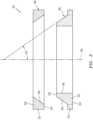
- the external die assembly 24 includes an inner clamp member 46 and an outer clamp member 48.
- the inner clamp member 46 is configured as an annular body with a base 50 and a flange 52; e.g., an annular rim.
- the inner clamp member 46 of FIG. 3 extends circumferentially about (e.g., completely around) the axis 28 so as to form a full hoop inner clamp member body.
- the inner clamp member 46 extends axially along the axis 28 from an inner clamp member first end 54 to an inner clamp member second end 56.
- the base 50 of the inner clamp member 46 extends radially between an inner clamp member inner surface 58 and an inner clamp member outer surface 60.
- the inner clamp member outer surface 60 of FIG. 3 has a frustoconical geometry.
- the inner clamp member outer surface 60 of FIG. 3 for example, tapers radially inward as that surface 60 extends axially along the axis 28 to the inner clamp member second end 56.
- the inner clamp member outer surface 60 is angularly offset from the axis 28 by an inner clamp member angle 62; e.g., an external die angle.
- This inner clamp member angle 62 may be an acute angle.
- the inner clamp member angle 62 may be greater than (or equal to) twenty-five degrees (25°) and less than (or equal to) forty degrees (40°); e.g., the angle 62 may be equal to thirty degrees (30°).
- the flange 52 is located at the inner clamp member first end 54.
- the flange 52 projects radially out from the base 50 and may be axially adjacent an edge of the inner clamp member outer surface 60.
- the outer clamp member 48 is configured as an annular body.
- the outer clamp member 48 of FIG. 3 extends circumferentially about (e.g., completely around) the axis 28 so as to form a full hoop outer clamp member body.
- the outer clamp member 48 extends axially along the axis 28 from an outer clamp member first end 64 to an outer clamp member second end 66.
- the outer clamp member 48 extends radially between an outer clamp member inner surface 68 and an outer clamp member outer surface 70.
- the outer clamp member inner surface 68 of FIG. 3 has a frustoconical geometry.
- the outer clamp member inner surface 68 is shaped and dimensioned to compliment (e.g., substantially mirror) the geometry of the inner clamp member outer surface 60.
- the outer clamp member inner surface 68 may thereby engage the inner clamp member outer surface 60 as described below in further detail.
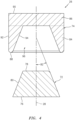
- the internal die assembly 26 includes an internal die clamp 72 and an internal die 74.
- the internal die clamp 72 extends axially along the axis 28 from a die clamp first end 76 to a die clamp second end 78.
- the internal die clamp 72 extends radially outward to a die clamp outer surface 80.
- This die clamp outer surface 80 extends circumferentially about (e.g., completely around) the axis 28.
- the die clamp outer surface 80 of FIG. 4 has a frustoconical geometry.
- the die clamp outer surface 80 of FIG. 4 for example, tapers radially inward as that surface 80 extends axially along the axis 28 from the die clamp first end 76 to the die clamp second end 78.
- the die clamp outer surface 80 is angularly offset from the axis 28 by a die clamp angle 82.
- This die clamp angle 82 may be an acute angle.
- the die clamp angle 82 is different (e.g., less) than the inner clamp member angle 62 (see FIG. 3 ).
- the die clamp angle 82 for example, may be greater than (or equal to) fifteen degrees (15°) and less than (or equal to) twenty-five degrees (25°); e.g., the angle 82 may be equal to twenty degrees (20°).
- the internal die 74 may have a generally cup-shaped body; e.g., a body with a generally U or V shaped cross-sectional geometry.
- the internal die 74 of FIG. 4 for example, includes a tubular rim 84 and a base 86; e.g., an end cap / base plate.
- the tubular rim 84 extends circumferentially about (e.g., completely around) the axis 28.
- the tubular rim 84 extends axially along the axis 28 from an internal die first end 88 to the base 86, which is disposed at an internal die second end 90.
- the tubular rim 84 extends radially between an internal die outer surface 92 and an internal die inner surface 94.
- the internal die inner surface 94 forms an aperture 96 (e.g., an indentation, pocket, etc.) in the internal die 74, which aperture 96 extends (e.g., partially) into the internal die 74 from the internal die first end 88 to the base 86.
- the internal die inner surface 94 is shaped and dimensioned to compliment (e.g., substantially mirror) the geometry of the die clamp outer surface 80.
- the internal die inner surface 94 may thereby engage the die clamp outer surface 80 as described below in further detail.
- the actuation system of FIG. 1 includes one or more actuators 98-102; e.g., linear actuators. Each of these actuators 98-102 is configured to hold and/or axially translate a respective one of the formation assembly components 22, 46, 48, 72, 74 along the axis 28. Each actuator 98-102 may by hydraulically, pneumatically and/or electromechanically driven.
- FIG. 5 is a flow diagram of a method 500 for forming the annular object. This method 500 is described below with reference to the formation assembly 20 of FIG. 1 . However, the method 500 is not limited to using the exemplary formation assembly described above.
- a frustoconical preform 104 is provided as shown, for example, in FIG. 6 .
- This frustoconical preform 104 may be constructed from sheet material.
- the frustoconical preform 104 may be constructed from a sheet of metal; e.g., sheet metal. Examples of the metal include, but are not limited to, aluminum (Al), titanium (Ti), or an alloy one or more of the foregoing metals.
- the frustoconical preform 104 of FIG. 6 is configured as a tubular body.
- the frustoconical preform 104 of FIG. 6 extends circumferentially about (e.g., completely around) the axis 28 so as to form a full hoop preform body.
- the frustoconical preform 104 extends axially along the axis 28 from a preform first end 106 to a preform second end 108.
- the frustoconical preform 104 extends radially between a preform outer surface 110 and a preform inner surface 112.
- the preform inner surface 112 forms a preform bore 114 in the frustoconical preform 104, which preform bore 114 extends axially along the axis 28 through the frustoconical preform 104 from the preform first end 106 to the preform second end 108.
- the frustoconical preform 104 and its surfaces 110 and 112 taper radially inwards as each of those elements 104, 110, 112 extends from the preform first end 106 to the preform second end 108.
- a diameter 116 of the frustoconical preform 104 at the preform first end 106 is greater than a diameter 118 of the frustoconical preform 104 at the preform second end 108.
- One or more or each preform element 104, 110, 112 may be angularly offset from the axis 28 by a preform angle 120.
- This preform angle 120 may be an acute angle.
- the preform angle 120 may be equal to the inner clamp member angle 62 (see FIG. 3 ); e.g., the external die angle.
- the preform angle 120 is different (e.g., greater) than the die clamp angle 82 (see FIG. 4 ).
- the preform angle 120 for example, may be greater than (or equal to) twenty-five degrees (25°) and less than (or equal to) forty degrees (40°); e.g., the angle 120 may be equal to thirty degrees (30°).
- the frustoconical preform 104 is clamped with (e.g., by) the external die assembly 24 as shown, for example, in FIG. 7 .
- the base 50 of the inner clamp member 46 may be inserted into the preform bore 114 such that the inner clamp member outer surface 60 radially engages (e.g., contacts) the preform inner surface 112 at the preform first end 106.
- the outer clamp member 48 may then be translated axially along the axis 28 until the outer clamp member inner surface 68 radially engages (e.g., contacts) the preform outer surface 110 at the preform first end 106.
- the frustoconical preform 104 may thereby be clamped radially between the clamp members 46 and 48.
- the frustoconical preform 104 is externally drawn to provide an externally drawn object 122 (see FIG. 9 ) as shown, for example, in the sequence of FIGS. 8 and 9 .
- the external die assembly 24 in other words, pulls the frustoconical preform 104 over and shapes the frustoconical preform 104 to the punch outer surface 34 and the die clamp outer surface 80.
- the portion of the frustoconical preform 104 drawn onto / over the punch outer surface 34 may substantially take the shape and dimensions of an outer portion of the finished annular object.
- the portion of the frustoconical preform 104 drawn onto / over the die clamp outer surface 80 is reshaped to increase the diameter 118 at the second end 108; e.g., the diameter 118 at the stage in FIG. 9 is greater than the diameter 118 at the stage in FIG. 8 .
- the drawing of the frustoconical preform 104 onto the punch 22 may be performed simultaneously with the drawing of the frustoconical preform 104 onto the die clamp 72.
- the method 500 of the present disclosure is not limited to such a simultaneous drawing.
- the frustoconical preform 104 may be partially or completely drawn onto the die clamp 72 before the drawing of the frustoconical preform 104 onto the punch 22, or vice versa.
- the translation of the external die assembly 24 may partially draw the frustoconical preform 104 onto the die clamp outer surface 80.
- the drawing of the frustoconical preform 104 onto the die clamp outer surface 80 may subsequently be completed by mating the internal die 74 with the internal die clamp 72.
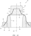
- the internal die 74 is mated with the internal die clamp 72 to clamp the externally drawn object 122 as shown, for example, in FIG. 10 .
- the internal die 74 may be translated axially along the axis 28 until the internal die inner surface 94 radially engages (e.g., contacts) the outer surface 110 at the second end 108.
- the externally drawn object 122 may thereby be clamped radially between the internal die clamp 72 and the internal die 74.
- the externally drawn object 122 is at least partially (or completely) internally drawn to provide an annular body 124 (see FIG. 11 ) as shown, for example, in the sequence of FIGS. 10 and 11 .
- the internal die assembly 26, which is clamped onto the externally drawn object 122 is translated axially along the axis 28 into the punch bore 38 to at least partially (or completely) draw the externally drawn object 122 against the punch inner surface 36.
- the internal die assembly 26, in other words, pulls the externally drawn object 122 along and shapes the externally drawn object 122 to the punch inner surface 36.
- the portion of the externally drawn object 122 drawn against the punch inner surface 36 may substantially take the shape and dimensions of an inner portion of the finished annular object.
- the distance of radial movement of the object's material is reduced when pressed against the punch inner surface 36. This in turn may reduce defects in the object's material such as, but not limited to, cracks and wrinkles.
- the internal drawing may be performed without intermediate annealing step(s), or with a reduced number of intermediate annealing step(s).
- the annular body 124 is heat treated. This heat treatment may be preformed while the annular body 124 is configured with the formation assembly 20. Alternatively, the heat treatment may be performed after the annular body 124 is removed from the formation assembly 20.
- the annular body 124 is trimmed to provide the finished annular object. For example, portions (e.g., see 126 and 128 in FIG. 11 ) of the annular body 124 which were used for clamping may be cut off.
- the method 500 may include one or more additional steps other than those discussed above.
- the internal drawing of the externally drawn object 122 may be performed iteratively and, between iterations, the object's material may be annealed or otherwise heat treated.
- one or more additional finishing operations e.g., polishing, etc.
- the method 500 of the present disclosure therefore, is not limited to the exemplary steps nor particular sequence of performing the exemplary steps described above.
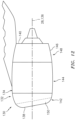
- FIG. 12 illustrates an aircraft propulsion system 130 for an aircraft such as, but not limited to, a commercial airliner or a cargo plane.
- the propulsion system 130 includes a nacelle 132 and a gas turbine engine.
- This gas turbine engine may be configured as a highbypass turbofan engine. Alternatively, the gas turbine engine may be configured as any other type of gas turbine engine capable of propelling the aircraft during flight.
- the nacelle 132 is configured to house and provide an aerodynamic cover for the gas turbine engine.
- An outer nacelle structure 134 of the nacelle 132 extends along an axial centerline 136 of the gas turbine engine between a nacelle forward end 138 and a nacelle aft end 140, which centerline 136 may be coaxial with the axis 28.
- the nacelle structure 134 of FIG. 12 includes a nacelle inlet structure 142, one or more fan cowls 144 (one such cowl visible in FIG. 12 ) and a nacelle aft structure 146, which may be configured as part of or include a thrust reverser system 148.
- the annular object formed with the assembly 20 of FIG. 1 and/or the method 500 of FIG. 5 may be configured as a portion of, an entirety of or otherwise include the inlet structure 142.
- the annular object for example, may be configured as an inlet lip 150 (e.g., a nose lip) of the inlet structure 142
Landscapes
- Engineering & Computer Science (AREA)
- Mechanical Engineering (AREA)
- Aviation & Aerospace Engineering (AREA)
- Shaping Metal By Deep-Drawing, Or The Like (AREA)
Claims (13)
- Procédé de formation d'un objet annulaire, comprenant :la fourniture d'une préforme tronconique (104) se prolongeant axialement le long d'un axe (28), dans laquelle une paroi latérale de la préforme tronconique (104) est décalée angulairement par rapport à l'axe (28) d'un angle de préforme (120) ;le serrage la préforme tronconique (104) avec un ensemble matrice externe (24), dans lequel une surface de l'ensemble matrice externe (24) en butée contre la préforme tronconique (104) est décalée angulairement par rapport à l'axe (28) d'un angle de matrice externe (62) ;la translation de l'ensemble matrice externe (24) axialement le long de l'axe (28) pour étirer externement la préforme tronconique (104) sur une surface externe (34) d'un poinçon (22) et une surface externe (80) d'une pince de matrice (72) pour fournir un corps étiré externement (122), dans lequel la surface externe (80) de la pince de matrice (72) est décalée angulairement par rapport à l'axe (28) d'un angle de pince de matrice (82) qui est différent de l'angle de préforme (120), et l'angle de pince de matrice (82) est différent de l'angle de matrice externe (62) ;l'accouplement d'une matrice (74) avec la pince de matrice (72) pour fournir un ensemble de matrice (26), dans lequel le corps étiré externement (122) est serré radialement entre la matrice (74) et la pince de matrice (72) ; etla translation de l'ensemble matrice (26) axialement le long de l'axe (28) et dans un alésage (38) du poinçon (22) pour tirer au moins partiellement internement le corps étiré externement (122) contre une surface interne (36) du poinçon (22).
- Procédé selon la revendication 1, dans lequel l'angle de serrage de la matrice (82) est inférieur à l'angle de préforme (120) .
- Procédé selon la revendication 1 ou 2, dans lequel l'angle de serrage de la matrice (82) est compris entre quinze degrés et vingt-cinq degrés.
- Procédé selon l'une quelconque des revendications précédentes, dans lequel l'angle de préforme (120) est compris entre vingt-cinq degrés et quarante degrés.
- Procédé selon l'une quelconque des revendications précédentes, dans lequel l'ensemble de matrice externe (24) comporte un élément de serrage interne (46) et un élément de serrage externe (48).
- Procédé selon la revendication 5, dans lequel la préforme tronconique (104) est serrée entre une surface externe (60) de l'élément de serrage interne (46) et une surface interne (68) de l'élément de serrage externe (48).
- Procédé selon la revendication 6, dans lequel la surface externe (60) de l'élément de serrage interne (46) est décalée angulairement par rapport à l'axe (28) par l'angle de matrice externe (62).
- Procédé selon la revendication 6 ou 7, dans lequel la surface de l'ensemble de matrice externe (24) est une surface externe (60) de l'élément de serrage interne (46).
- Procédé selon l'une quelconque des revendications précédentes, dans lequel l'angle de matrice externe (62) est égal à l'angle de préforme (120).
- Procédé selon l'une quelconque des revendications précédentes, dans lequel la préforme tronconique (104) comprend du métal.
- Procédé selon l'une quelconque des revendications précédentes, dans lequel l'objet annulaire comprend une lèvre d'entrée (150) d'une nacelle de système de propulsion d'aéronef (132) .
- Procédé selon l'une quelconque des revendications précédentes, comprenant également le recuit du corps étiré externement (122) après la translation de l'ensemble matrice (26) .
- Procédé selon l'une quelconque des revendications précédentes, dans lequel l'angle de serrage de la matrice (82) est inférieur à l'angle de la matrice externe (62).
Applications Claiming Priority (1)
| Application Number | Priority Date | Filing Date | Title |
|---|---|---|---|
| US16/779,986 US20210237139A1 (en) | 2020-02-03 | 2020-02-03 | Methods and assemblies for forming an annular object |
Publications (2)
| Publication Number | Publication Date |
|---|---|
| EP3858509A1 EP3858509A1 (fr) | 2021-08-04 |
| EP3858509B1 true EP3858509B1 (fr) | 2025-03-26 |
Family
ID=74418351
Family Applications (1)
| Application Number | Title | Priority Date | Filing Date |
|---|---|---|---|
| EP21154412.7A Active EP3858509B1 (fr) | 2020-02-03 | 2021-01-29 | Procédé et ensemble de formation d'un objet annulaire |
Country Status (2)
| Country | Link |
|---|---|
| US (1) | US20210237139A1 (fr) |
| EP (1) | EP3858509B1 (fr) |
Families Citing this family (4)
| Publication number | Priority date | Publication date | Assignee | Title |
|---|---|---|---|---|
| FR3115222B1 (fr) * | 2020-10-21 | 2023-05-12 | Safran Nacelles | Fabrication de secteurs annulaires pour la réalisation d’une lèvre d’entrée d’air |
| GB2618123A (en) * | 2022-04-28 | 2023-11-01 | Rohr Inc | A method and arrangement for forming a lip skin for a nacelle |
| EP4268990A1 (fr) * | 2022-04-28 | 2023-11-01 | Rohr, Inc. | Procédé et agencement pour former un revêtement de lèvre pour une nacelle |
| EP4275835B1 (fr) * | 2022-05-12 | 2024-12-04 | Creuzet Aeronautique | Procédé de fabrication de peau de lèvre d'entrée |
Family Cites Families (3)
| Publication number | Priority date | Publication date | Assignee | Title |
|---|---|---|---|---|
| GB0812614D0 (en) * | 2008-07-10 | 2008-08-20 | Univ Ulster | Metal forming |
| GB201312228D0 (en) * | 2013-07-08 | 2013-08-21 | Ludlow Michael | A lip skin and a method and apparatus for forming a lip skin |
| CN109692911B (zh) * | 2018-12-10 | 2020-10-16 | 上海航天设备制造总厂有限公司 | 一种大型环壳零件整体成形装置和方法 |
-
2020
- 2020-02-03 US US16/779,986 patent/US20210237139A1/en not_active Abandoned
-
2021
- 2021-01-29 EP EP21154412.7A patent/EP3858509B1/fr active Active
Also Published As
| Publication number | Publication date |
|---|---|
| US20210237139A1 (en) | 2021-08-05 |
| EP3858509A1 (fr) | 2021-08-04 |
Similar Documents
| Publication | Publication Date | Title |
|---|---|---|
| EP3858509A1 (fr) | Procédé et ensemble de formation d'un objet annulaire | |
| US9114882B2 (en) | Fan case and mount ring snap fit assembly | |
| US10669970B2 (en) | Thrust reverser system having limited aerodynamic disturbance | |
| US9656761B2 (en) | Lipskin for a nacelle and methods of making the same | |
| EP3750661B1 (fr) | Formation d'une admission de nacelle pour un système de propulsion de moteur de turbine | |
| US11219935B2 (en) | Annular part and a method and apparatus for forming an annular part | |
| EP3689489B1 (fr) | Procédé et appareil pour former un bord d'attaque de nacelle | |
| WO2012116999A1 (fr) | Revêtement de bord et procédé et appareil de formation de revêtement de bord | |
| EP2937549B1 (fr) | Inverseur de poussée à une ou plusieurs parties en cascade de coin de renfort | |
| CA2601659A1 (fr) | Structure annulaire de turbomoteur et procede de fabrication | |
| US10502161B2 (en) | Cascade system and apparatus | |
| US10316793B2 (en) | Thrust reverser track beam with integrated actuator fitting | |
| CA2602994C (fr) | Carter annulaire pour moteur a turbine a gaz et methode de fabrication connexe | |
| US20230347402A1 (en) | Method and arrangement for forming a lip skin for a nacelle | |
| CA2602981A1 (fr) | Carter annulaire pour moteur a turbine a gaz et methode de fabrication connexe | |
| US9347398B2 (en) | Actuator support system and apparatus | |
| US20080080974A1 (en) | Annular gas turbine engine case and method of manufacturing | |
| EP4268990A1 (fr) | Procédé et agencement pour former un revêtement de lèvre pour une nacelle | |
| EP3741680B1 (fr) | Cloison d'entrée comportant une rainure de ventilation | |
| US11525372B2 (en) | Diaphragm latch | |
| US20200147662A1 (en) | Blank for a flow forming method | |
| EP3081758B1 (fr) | Ensemble de soufflante d'un moteur d'aéronef avec un dispositif de retenue de verrouillage d'aubes | |
| US20250179939A1 (en) | Design of a rear-cone exhaust duct for additive manufacturing |
Legal Events
| Date | Code | Title | Description |
|---|---|---|---|
| PUAI | Public reference made under article 153(3) epc to a published international application that has entered the european phase |
Free format text: ORIGINAL CODE: 0009012 |
|
| STAA | Information on the status of an ep patent application or granted ep patent |
Free format text: STATUS: THE APPLICATION HAS BEEN PUBLISHED |
|
| AK | Designated contracting states |
Kind code of ref document: A1 Designated state(s): AL AT BE BG CH CY CZ DE DK EE ES FI FR GB GR HR HU IE IS IT LI LT LU LV MC MK MT NL NO PL PT RO RS SE SI SK SM TR |
|
| STAA | Information on the status of an ep patent application or granted ep patent |
Free format text: STATUS: REQUEST FOR EXAMINATION WAS MADE |
|
| 17P | Request for examination filed |
Effective date: 20220204 |
|
| RBV | Designated contracting states (corrected) |
Designated state(s): AL AT BE BG CH CY CZ DE DK EE ES FI FR GB GR HR HU IE IS IT LI LT LU LV MC MK MT NL NO PL PT RO RS SE SI SK SM TR |
|
| GRAP | Despatch of communication of intention to grant a patent |
Free format text: ORIGINAL CODE: EPIDOSNIGR1 |
|
| STAA | Information on the status of an ep patent application or granted ep patent |
Free format text: STATUS: GRANT OF PATENT IS INTENDED |
|
| INTG | Intention to grant announced |
Effective date: 20241023 |
|
| GRAS | Grant fee paid |
Free format text: ORIGINAL CODE: EPIDOSNIGR3 |
|
| GRAA | (expected) grant |
Free format text: ORIGINAL CODE: 0009210 |
|
| STAA | Information on the status of an ep patent application or granted ep patent |
Free format text: STATUS: THE PATENT HAS BEEN GRANTED |
|
| AK | Designated contracting states |
Kind code of ref document: B1 Designated state(s): AL AT BE BG CH CY CZ DE DK EE ES FI FR GB GR HR HU IE IS IT LI LT LU LV MC MK MT NL NO PL PT RO RS SE SI SK SM TR |
|
| REG | Reference to a national code |
Ref country code: GB Ref legal event code: FG4D |
|
| REG | Reference to a national code |
Ref country code: CH Ref legal event code: EP |
|
| REG | Reference to a national code |
Ref country code: DE Ref legal event code: R096 Ref document number: 602021027990 Country of ref document: DE |
|
| REG | Reference to a national code |
Ref country code: IE Ref legal event code: FG4D |
|
| PG25 | Lapsed in a contracting state [announced via postgrant information from national office to epo] |
Ref country code: RS Free format text: LAPSE BECAUSE OF FAILURE TO SUBMIT A TRANSLATION OF THE DESCRIPTION OR TO PAY THE FEE WITHIN THE PRESCRIBED TIME-LIMIT Effective date: 20250626 |
|
| PG25 | Lapsed in a contracting state [announced via postgrant information from national office to epo] |
Ref country code: FI Free format text: LAPSE BECAUSE OF FAILURE TO SUBMIT A TRANSLATION OF THE DESCRIPTION OR TO PAY THE FEE WITHIN THE PRESCRIBED TIME-LIMIT Effective date: 20250326 |
|
| REG | Reference to a national code |
Ref country code: LT Ref legal event code: MG9D |
|
| PG25 | Lapsed in a contracting state [announced via postgrant information from national office to epo] |
Ref country code: NO Free format text: LAPSE BECAUSE OF FAILURE TO SUBMIT A TRANSLATION OF THE DESCRIPTION OR TO PAY THE FEE WITHIN THE PRESCRIBED TIME-LIMIT Effective date: 20250626 |
|
| PG25 | Lapsed in a contracting state [announced via postgrant information from national office to epo] |
Ref country code: HR Free format text: LAPSE BECAUSE OF FAILURE TO SUBMIT A TRANSLATION OF THE DESCRIPTION OR TO PAY THE FEE WITHIN THE PRESCRIBED TIME-LIMIT Effective date: 20250326 |
|
| PG25 | Lapsed in a contracting state [announced via postgrant information from national office to epo] |
Ref country code: LV Free format text: LAPSE BECAUSE OF FAILURE TO SUBMIT A TRANSLATION OF THE DESCRIPTION OR TO PAY THE FEE WITHIN THE PRESCRIBED TIME-LIMIT Effective date: 20250326 |
|
| PG25 | Lapsed in a contracting state [announced via postgrant information from national office to epo] |
Ref country code: GR Free format text: LAPSE BECAUSE OF FAILURE TO SUBMIT A TRANSLATION OF THE DESCRIPTION OR TO PAY THE FEE WITHIN THE PRESCRIBED TIME-LIMIT Effective date: 20250627 Ref country code: BG Free format text: LAPSE BECAUSE OF FAILURE TO SUBMIT A TRANSLATION OF THE DESCRIPTION OR TO PAY THE FEE WITHIN THE PRESCRIBED TIME-LIMIT Effective date: 20250326 |
|
| REG | Reference to a national code |
Ref country code: NL Ref legal event code: MP Effective date: 20250326 |
|
| PG25 | Lapsed in a contracting state [announced via postgrant information from national office to epo] |
Ref country code: NL Free format text: LAPSE BECAUSE OF FAILURE TO SUBMIT A TRANSLATION OF THE DESCRIPTION OR TO PAY THE FEE WITHIN THE PRESCRIBED TIME-LIMIT Effective date: 20250326 |
|
| PG25 | Lapsed in a contracting state [announced via postgrant information from national office to epo] |
Ref country code: SE Free format text: LAPSE BECAUSE OF FAILURE TO SUBMIT A TRANSLATION OF THE DESCRIPTION OR TO PAY THE FEE WITHIN THE PRESCRIBED TIME-LIMIT Effective date: 20250326 |
|
| REG | Reference to a national code |
Ref country code: AT Ref legal event code: MK05 Ref document number: 1778564 Country of ref document: AT Kind code of ref document: T Effective date: 20250326 |
|
| PG25 | Lapsed in a contracting state [announced via postgrant information from national office to epo] |
Ref country code: SM Free format text: LAPSE BECAUSE OF FAILURE TO SUBMIT A TRANSLATION OF THE DESCRIPTION OR TO PAY THE FEE WITHIN THE PRESCRIBED TIME-LIMIT Effective date: 20250326 |
|
| PG25 | Lapsed in a contracting state [announced via postgrant information from national office to epo] |
Ref country code: PT Free format text: LAPSE BECAUSE OF FAILURE TO SUBMIT A TRANSLATION OF THE DESCRIPTION OR TO PAY THE FEE WITHIN THE PRESCRIBED TIME-LIMIT Effective date: 20250728 Ref country code: ES Free format text: LAPSE BECAUSE OF FAILURE TO SUBMIT A TRANSLATION OF THE DESCRIPTION OR TO PAY THE FEE WITHIN THE PRESCRIBED TIME-LIMIT Effective date: 20250326 |
|
| PG25 | Lapsed in a contracting state [announced via postgrant information from national office to epo] |
Ref country code: PL Free format text: LAPSE BECAUSE OF FAILURE TO SUBMIT A TRANSLATION OF THE DESCRIPTION OR TO PAY THE FEE WITHIN THE PRESCRIBED TIME-LIMIT Effective date: 20250326 Ref country code: IT Free format text: LAPSE BECAUSE OF FAILURE TO SUBMIT A TRANSLATION OF THE DESCRIPTION OR TO PAY THE FEE WITHIN THE PRESCRIBED TIME-LIMIT Effective date: 20250326 |
|
| PG25 | Lapsed in a contracting state [announced via postgrant information from national office to epo] |
Ref country code: AT Free format text: LAPSE BECAUSE OF FAILURE TO SUBMIT A TRANSLATION OF THE DESCRIPTION OR TO PAY THE FEE WITHIN THE PRESCRIBED TIME-LIMIT Effective date: 20250326 |
|
| PG25 | Lapsed in a contracting state [announced via postgrant information from national office to epo] |
Ref country code: EE Free format text: LAPSE BECAUSE OF FAILURE TO SUBMIT A TRANSLATION OF THE DESCRIPTION OR TO PAY THE FEE WITHIN THE PRESCRIBED TIME-LIMIT Effective date: 20250326 |
|
| PG25 | Lapsed in a contracting state [announced via postgrant information from national office to epo] |
Ref country code: RO Free format text: LAPSE BECAUSE OF FAILURE TO SUBMIT A TRANSLATION OF THE DESCRIPTION OR TO PAY THE FEE WITHIN THE PRESCRIBED TIME-LIMIT Effective date: 20250326 |
|
| PG25 | Lapsed in a contracting state [announced via postgrant information from national office to epo] |
Ref country code: SK Free format text: LAPSE BECAUSE OF FAILURE TO SUBMIT A TRANSLATION OF THE DESCRIPTION OR TO PAY THE FEE WITHIN THE PRESCRIBED TIME-LIMIT Effective date: 20250326 |
|
| PG25 | Lapsed in a contracting state [announced via postgrant information from national office to epo] |
Ref country code: IS Free format text: LAPSE BECAUSE OF FAILURE TO SUBMIT A TRANSLATION OF THE DESCRIPTION OR TO PAY THE FEE WITHIN THE PRESCRIBED TIME-LIMIT Effective date: 20250726 |
|
| REG | Reference to a national code |
Ref country code: DE Ref legal event code: R097 Ref document number: 602021027990 Country of ref document: DE |
|
| PGFP | Annual fee paid to national office [announced via postgrant information from national office to epo] |
Ref country code: GB Payment date: 20251220 Year of fee payment: 6 |
|
| PG25 | Lapsed in a contracting state [announced via postgrant information from national office to epo] |
Ref country code: DK Free format text: LAPSE BECAUSE OF FAILURE TO SUBMIT A TRANSLATION OF THE DESCRIPTION OR TO PAY THE FEE WITHIN THE PRESCRIBED TIME-LIMIT Effective date: 20250326 |
|
| PGFP | Annual fee paid to national office [announced via postgrant information from national office to epo] |
Ref country code: FR Payment date: 20251217 Year of fee payment: 6 |
|
| PG25 | Lapsed in a contracting state [announced via postgrant information from national office to epo] |
Ref country code: CZ Free format text: LAPSE BECAUSE OF FAILURE TO SUBMIT A TRANSLATION OF THE DESCRIPTION OR TO PAY THE FEE WITHIN THE PRESCRIBED TIME-LIMIT Effective date: 20250326 |
|
| PLBE | No opposition filed within time limit |
Free format text: ORIGINAL CODE: 0009261 |
|
| STAA | Information on the status of an ep patent application or granted ep patent |
Free format text: STATUS: NO OPPOSITION FILED WITHIN TIME LIMIT |
|
| REG | Reference to a national code |
Ref country code: CH Ref legal event code: L10 Free format text: ST27 STATUS EVENT CODE: U-0-0-L10-L00 (AS PROVIDED BY THE NATIONAL OFFICE) Effective date: 20260211 |
|
| 26N | No opposition filed |
Effective date: 20260105 |
|
| PGFP | Annual fee paid to national office [announced via postgrant information from national office to epo] |
Ref country code: DE Payment date: 20251217 Year of fee payment: 6 |