EP3858559B1 - Plateforme de dressage, système de capteurs, avion et procédé de fonctionnement d'une plateforme de dressage - Google Patents
Plateforme de dressage, système de capteurs, avion et procédé de fonctionnement d'une plateforme de dressage Download PDFInfo
- Publication number
- EP3858559B1 EP3858559B1 EP20201481.7A EP20201481A EP3858559B1 EP 3858559 B1 EP3858559 B1 EP 3858559B1 EP 20201481 A EP20201481 A EP 20201481A EP 3858559 B1 EP3858559 B1 EP 3858559B1
- Authority
- EP
- European Patent Office
- Prior art keywords
- platform
- joint
- axis
- joints
- biaxial
- Prior art date
- Legal status (The legal status is an assumption and is not a legal conclusion. Google has not performed a legal analysis and makes no representation as to the accuracy of the status listed.)
- Active
Links
Images


Classifications
-
- F—MECHANICAL ENGINEERING; LIGHTING; HEATING; WEAPONS; BLASTING
- F16—ENGINEERING ELEMENTS AND UNITS; GENERAL MEASURES FOR PRODUCING AND MAINTAINING EFFECTIVE FUNCTIONING OF MACHINES OR INSTALLATIONS; THERMAL INSULATION IN GENERAL
- F16M—FRAMES, CASINGS OR BEDS OF ENGINES, MACHINES OR APPARATUS, NOT SPECIFIC TO ENGINES, MACHINES OR APPARATUS PROVIDED FOR ELSEWHERE; STANDS; SUPPORTS
- F16M11/00—Stands or trestles as supports for apparatus or articles placed thereon ; Stands for scientific apparatus such as gravitational force meters
- F16M11/02—Heads
- F16M11/18—Heads with mechanism for moving the apparatus relatively to the stand
-
- B—PERFORMING OPERATIONS; TRANSPORTING
- B25—HAND TOOLS; PORTABLE POWER-DRIVEN TOOLS; MANIPULATORS
- B25J—MANIPULATORS; CHAMBERS PROVIDED WITH MANIPULATION DEVICES
- B25J9/00—Program-controlled manipulators
- B25J9/003—Program-controlled manipulators having parallel kinematics
- B25J9/0045—Program-controlled manipulators having parallel kinematics with kinematics chains having a rotary joint at the base
-
- F—MECHANICAL ENGINEERING; LIGHTING; HEATING; WEAPONS; BLASTING
- F16—ENGINEERING ELEMENTS AND UNITS; GENERAL MEASURES FOR PRODUCING AND MAINTAINING EFFECTIVE FUNCTIONING OF MACHINES OR INSTALLATIONS; THERMAL INSULATION IN GENERAL
- F16M—FRAMES, CASINGS OR BEDS OF ENGINES, MACHINES OR APPARATUS, NOT SPECIFIC TO ENGINES, MACHINES OR APPARATUS PROVIDED FOR ELSEWHERE; STANDS; SUPPORTS
- F16M11/00—Stands or trestles as supports for apparatus or articles placed thereon ; Stands for scientific apparatus such as gravitational force meters
- F16M11/02—Heads
- F16M11/04—Means for attachment of apparatus; Means allowing adjustment of the apparatus relatively to the stand
- F16M11/06—Means for attachment of apparatus; Means allowing adjustment of the apparatus relatively to the stand allowing pivoting
- F16M11/12—Means for attachment of apparatus; Means allowing adjustment of the apparatus relatively to the stand allowing pivoting in more than one direction
- F16M11/121—Means for attachment of apparatus; Means allowing adjustment of the apparatus relatively to the stand allowing pivoting in more than one direction constituted of several dependent joints
- F16M11/123—Means for attachment of apparatus; Means allowing adjustment of the apparatus relatively to the stand allowing pivoting in more than one direction constituted of several dependent joints the axis of rotation intersecting in a single point, e.g. by using gimbals
-
- F—MECHANICAL ENGINEERING; LIGHTING; HEATING; WEAPONS; BLASTING
- F16—ENGINEERING ELEMENTS AND UNITS; GENERAL MEASURES FOR PRODUCING AND MAINTAINING EFFECTIVE FUNCTIONING OF MACHINES OR INSTALLATIONS; THERMAL INSULATION IN GENERAL
- F16M—FRAMES, CASINGS OR BEDS OF ENGINES, MACHINES OR APPARATUS, NOT SPECIFIC TO ENGINES, MACHINES OR APPARATUS PROVIDED FOR ELSEWHERE; STANDS; SUPPORTS
- F16M11/00—Stands or trestles as supports for apparatus or articles placed thereon ; Stands for scientific apparatus such as gravitational force meters
- F16M11/02—Heads
- F16M11/04—Means for attachment of apparatus; Means allowing adjustment of the apparatus relatively to the stand
- F16M11/06—Means for attachment of apparatus; Means allowing adjustment of the apparatus relatively to the stand allowing pivoting
- F16M11/12—Means for attachment of apparatus; Means allowing adjustment of the apparatus relatively to the stand allowing pivoting in more than one direction
- F16M11/14—Means for attachment of apparatus; Means allowing adjustment of the apparatus relatively to the stand allowing pivoting in more than one direction with ball-joint
-
- G—PHYSICS
- G02—OPTICS
- G02B—OPTICAL ELEMENTS, SYSTEMS OR APPARATUS
- G02B7/00—Mountings, adjusting means, or light-tight connections, for optical elements
- G02B7/18—Mountings, adjusting means, or light-tight connections, for optical elements for prisms; for mirrors
- G02B7/182—Mountings, adjusting means, or light-tight connections, for optical elements for prisms; for mirrors for mirrors
- G02B7/1821—Mountings, adjusting means, or light-tight connections, for optical elements for prisms; for mirrors for mirrors for rotating or oscillating mirrors
-
- B—PERFORMING OPERATIONS; TRANSPORTING
- B64—AIRCRAFT; AVIATION; COSMONAUTICS
- B64U—UNMANNED AERIAL VEHICLES [UAV]; EQUIPMENT THEREFOR
- B64U2101/00—UAVs specially adapted for particular uses or applications
- B64U2101/30—UAVs specially adapted for particular uses or applications for imaging, photography or videography
Definitions
- the present invention relates to a targeting platform, in particular for a sensor device, a sensor system with such a targeting platform and an aircraft which has a sensor system. Furthermore, the invention relates to a method for operating an alignment platform.
- Optical sensors, radar sensors or other such surveillance sensors or mirrors of sensor arrays are often housed on pivoting aiming platforms.
- pivoting aiming platforms For example, in aircraft, particularly in unmanned aircraft such as drones, guided missiles or the like, it may be necessary to pivot a sensor device about at least two axes in order to achieve sufficiently large spatial coverage in combination with high image resolution.
- the opening angle of a field of view of the sensor is typically dependent on the sensor resolution.
- the performance of the sensor or mirror often depends on its size. It is therefore desirable to provide the sensor or mirror with as much space as possible within the available installation space and to reduce or as far as possible avoid shadowing of the mirror or sensor as a result of the pivoting movement.
- alignment platforms as described above can also be used for other applications, e.g. for aligning or moving tools, lighting devices or the like.
- a target platform in particular for a sensor device, is provided.
- the alignment platform comprises a first platform with a first bearing point of a first two-axis joint, a first bearing point of a second two-axis joint and a first bearing point of a third two-axis joint, the two-axis joints each having or defining two rotational degrees of freedom, and the first bearing points being arranged to form a first triangle, and a second platform with a second bearing point of a first three-axis joint, a second Bearing point of a second three-axis joint and a second bearing point of a third three-axis joint, the three-axis joints each having or defining three rotational degrees of freedom, and the second bearing points being arranged in a second triangle.
- the first platform is designed as a base and the second platform as a carrier platform for holding the sensor device or a component to be moved.
- the second platform is designed as a base and the first platform as a carrier platform for holding the sensor device or a component to be moved.
- the base can be realized, for example, as a plate, frame or generally as a frame on which at least three first bearing points are provided which are spaced apart from one another and lie in one plane, on which the respective two- or three-axis joints are arranged or attached in whole or in part.
- the carrier platform can be implemented in particular as a plate, frame or generally as a frame and is used to accommodate or hold a sensor device, in particular on a side facing away from the base.
- At least three second bearing points which are spaced apart from one another and lie in one plane, are provided on the carrier platform, on which the respective two- or three-axis joints are arranged or attached in whole or in part.
- the two-axis joints define a first axis or drive axis and a second axis or inner axis perpendicular to the drive axis.
- the three-axis joints define three mutually perpendicular axes of rotation.
- the alignment platform according to the invention also includes a first connecting member, which is mounted on the first two-axis joint and the first three-axis joint and extends with a fixed length between the first bearing point of the first two-axis joint and the second bearing point of the first three-axis joint, one on the second two-axis joint and the second three-axis joint mounted second connecting member, which extends with a fixed length between the first bearing point of the second two-axis joint and the second bearing point of the second three-axis joint, and a third connecting member mounted on the third two-axis joint and the third three-axis joint, which extends with a fixed length between the first bearing point of the third two-axis joint and the second bearing point of the third three-axis joint.
- the connecting links each have a fixed length or are designed to be of invariable length.
- the connecting members can be designed as rods, columns or generally as supports or beams that cannot be changed in length.
- the connecting links are each mounted on a two-axis joint of the first platform and a three-axis joint of the second platform.
- a respective connecting member extends between a respective first bearing point of the base and a second bearing point of the carrier platform.
- First bearing points of the two-axis joints are provided on the first platform and second bearing points of the three-axis joints are provided on the second platform.
- the two degrees of freedom of the two-axis joints and the three degrees of freedom of the three-axis joints are not necessarily implemented completely at the respective bearing point in a single structural unit.
- a first end of the respective link can be mounted on the corresponding first bearing point of the first platform so that it can only rotate about one axis, while a second axis perpendicular to this axis is defined by a joint structure of the link, so that a two-axis joint is formed.
- the link at the corresponding second bearing point of the second platform can be pivoted about two mutually perpendicular axes of rotation, while a third axis of rotation perpendicular to these two axes of rotation is defined by a joint structure of the link, so that a three-axis joint is formed becomes.
- joints defining two degrees of freedom can be provided at the first bearing points, on which joints the connecting members are mounted with a first end so as to be rotatable about two mutually perpendicular axes.
- joints defining three degrees of freedom can be provided at each of the second bearing points, on which joints the connecting members are mounted with a second end so that they can rotate about three axes that are perpendicular to one another.
- the alignment platform also has a first drive device, a second drive device and a third drive device, one drive device being coupled to a respective two-axis joint in order to rotate the connecting link mounted on the respective two-axis joint about a drive axis of rotation of the two-axis joint.
- the first drive device can be coupled to the first two-axis joint, the second drive device to the second drive device and the third drive device to the third two-axis joint.
- the drive devices which can be implemented in the form of electric motors, hydraulic actuators or the like, are each kinematically coupled to the drive axis of rotation of a respective two-axis joint, so that the connecting link mounted on this two-axis joint can be pivoted about the drive axis by the respective drive device.
- a parallel kinematics is realized.
- a sensor system in particular for an aircraft, the sensor system having a targeting platform according to the first aspect of the invention and a sensor device which is arranged on the carrier platform.
- the sensor device can in particular be a radar sensor device, an optical sensor, a mirror or the like.
- the aiming platform can be integrated into a seeker head of an unmanned missile or generally into an unmanned missile.
- an aircraft for example an unmanned aerial vehicle, is provided with a sensor system according to the second aspect of the invention.
- a method for operating an aiming platform according to the first aspect of the invention includes pivoting the connecting links by means of the drive devices about the respective drive axis of rotation relative to a neutral position.
- a first perimeter of the first triangle and a second perimeter of the second triangle are arranged concentrically with one another and the first bearing points of the two-axis joints and the second bearing points of the three-axis joints are spaced apart relative to one another by a neutral roll angle with respect to a roll axis, the roll axis being perpendicular stands on a plane defined by the second bearing points and passes through a center point of the second circumference.
- the center point of the second circumference and a center point of the first circumference are both located on a central axis which is perpendicular to a plane defined by the first bearing points and passes through the center point of the first circumference.
- the pivoting of the connecting links includes an individual or independent operation of the drive devices in such a way that by pivoting the connecting links about the respective drive axis of rotation, the second platform is tilted by an angle of inclination relative to a central axis that is stationary in relation to the first platform and is rotated about the roll axis .
- One of the ideas on which the invention is based is to implement a targeting platform as parallel kinematics, with a first platform and a second Platform are connected to one another by three connecting members and each of these connecting members is mounted on a two-axis bearing defining two rotational degrees of freedom on the first platform and on a three-axis bearing defining three degrees of rotational freedom.
- the bearing points at which the connecting links are supported on the first platform are arranged as a triangle on the first platform and thus define a first plane and the bearing points at which the connecting links are stored on the second platform are each arranged as a triangle on the second Arranged platform and thus define a second level.
- n is present 5 (3 connecting links plus first platform plus second platform)
- g is present 6 (3 two-axis joints plus 3 three-axis joints)
- ⁇ f i results in 15 (3 times 2 for the two-axis joints and 3 times 3 for the three-axis joints)
- F id is 0.
- three rotational degrees of freedom are achieved, so that the second platform can perform a tilting movement in all directions relative to the first platform and a rolling movement about its surface normal or roll axis. Consequently, the leveling platform according to the invention has only rotational degrees of freedom on the output side.
- first platform and the second platform are movable relative to each other solely due to rotational movements of the connecting members, wherein the rotational movements of the links are guided by the two-axis joints and the three-axis joints.
- the two-axis joints and the three-axis joints exclusively have rotational degrees of freedom.
- an alignment platform is thus realized with a minimum number of components, with which a carrier platform can be tilted and rolled.
- a tilting and rolling movement By combining a tilting and rolling movement, high angles of inclination of the carrier platform relative to the base can be achieved in a confined space.
- Another advantage is that the combination of tilting and rolling allows kinematic singularities to be avoided in a targeted manner. This improves the reliability of the alignment platform and, at the same time, increases the flexibility with regard to adjustable tilt and roll rates.
- kinematics with three rotational degrees of freedom are created with a minimal number of components, so that collisions with surrounding structures can be avoided more easily through the combination of tilting and rolling movements.
- the method for operating the alignment platform provides for the second platform and the first platform to be moved relative to one another out of a neutral position in which the platforms are slightly rolled relative to one another, the pivoting space is advantageously further reduced.
- the first connecting link, the second connecting link and the third connecting link each have the same length. This results in a symmetrical structure in which the two-axis joints and the three-axis joints are arranged in parallel planes in the neutral position. This makes it easier to control the movement of the platforms and is also advantageous for the mechanical rigidity and thus the precision of the alignment platform.
- first bearing points of the two-axis joints are spaced apart relative to one another by an angle of greater than or equal to 90 degrees and less than 180 degrees in relation to a center point of a first circumference of the first triangle defined by the arrangement of the first bearing points and /or that the second bearing points of the three-axis joints are spaced apart relative to one another by an angle of greater than or equal to 90 degrees and less than 180 degrees with respect to a center point of a second circumference of the second triangle defined by the arrangement of the second bearing points.
- the first bearing points of the two-axis joints define a first triangle and the second bearing points of the three-axis joints define a second triangle.
- a point of intersection of the axes of rotation of the respective joint defines a corner of the triangle.
- the corners of the first triangle lie in or define a first plane and the corners of the second triangle lie in or define a second plane.
- a first circumcircle can be added to the first triangle, on which the corners of the first triangle lie, be formed.
- a second circumcircle, on which the corners of the second triangle lie, can be formed for the second triangle.
- the corners of the triangles may be spaced relative to each other by 90 degrees or more with respect to a center point of the respective perimeter but less than 180 degrees from each other, where the sum of the angles is 360 degrees. This facilitates the pivoting of the links by means of the driving devices.
- first triangle and/or the second triangle are equilateral triangles.
- the corners of the triangles or the joints are spaced apart by an angle of 120 degrees in relation to the center point of the respective circumference. This results in a symmetrical structure, which has an advantageous effect on the rigidity and inertia of the target platform.
- the second perimeter may have a smaller diameter than the first perimeter. This is particularly advantageous when the second platform forms the carrier platform, since in this way, on the one hand, the mass of the second platform is reduced and the load on the connecting links and the drive devices is reduced as a result. In addition, this further reduces the space required for the second platform.
- the drive axes of rotation of the two-axis joints extend tangentially to a circumference of the first triangle defined by the two-axis joints. Accordingly, the drive axes of rotation can be arranged tangentially to the first circumference, in particular in the first plane. This achieves an even more compact construction of the alignment platform.
- the two-axis joints can be designed as cardan joints.
- Cardan joints have the advantage that they can be implemented in a robust and cost-effective manner.
- both rotational degrees of freedom of the two-axis joint are realized by a single joint structure arranged on the first platform.
- the three-axis joints can be designed as ball joints.
- Ball joints have the advantage that they can be implemented in a robust and cost-effective manner. Furthermore, they advantageously have a very compact structure. In this case, all three rotational degrees of freedom of the three-axis joint are realized by a single joint structure arranged on the second platform.
- At least one of the connecting members is prestressed against rotation about an inner axis of rotation of the respective two-axis joint, which axis is perpendicular to the drive axis of rotation.
- the internal axis of rotation can be prestressed by means of a torsion spring.
- tension-compression springs are tensioned between the respective connecting link and the drive axis of rotation of the respective two-axis joint.
- the carrier platform can be designed as a plate-shaped part. This offers the advantage that flat sensors such. B. optical sensors, radar sensors or mirrors can be easily mounted on the support platform.
- the drive device is operated individually in each case in such a way that a current roll angle relative to the neutral roll angle is controlled as a function of the inclination angle.
- the current roll angle as the difference from the neutral roll angle depends on the angle of inclination according to a fixed function and the drive device is controlled accordingly. This allows singularities, such as extended positions, to be avoided in a simple manner and very simple and robust control of the movement of the second platform can be achieved.
- the course of an axis, a direction or a structure "along" another axis, direction or structure is understood to mean that this, in particular the tangents resulting in a respective point of the structures each run at an angle of less than or equal to 45 degrees, preferably less than 30 degrees, and particularly preferably parallel to one another.
- directional information and axes in particular directional information and axes that relate to the course of physical structures, the course of an axis, a direction or a structure "transverse" to another axis, direction or structure is understood here to mean that this, in particular the tangents resulting in a respective point of the structures each run at an angle of greater than or equal to 45 degrees, preferably greater than or equal to 60 degrees and particularly preferably perpendicular to one another.
- the aiming platform 1 is not limited to use in a sensor system.
- a tool, an illumination device, a drive device or another structure or component can also be aligned, displaced or moved.
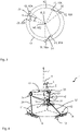
- the alignment platform 1 is in 1 shown in a simplified manner similar to a mechanical or kinematic equivalent circuit diagram.
- the aiming platform 1 may include a first platform 10, a second platform 20, a first link 31, a second link 32, a third link 33, first drive means 41, second drive means 42 and third drive means 43.
- the first platform 10 is in 1 shown only symbolically as a stationary structure.
- the first platform 10 can be implemented as a frame, for example as a frame or plate.
- a first two-axis joint 11, a second two-axis joint 12 and a third two-axis joint 13 can be provided on the first platform 10.
- the first two-axis joint 11, the second two-axis joint 12 and the third two-axis joint 13 each have two rotational degrees of freedom. In particular, only rotational degrees of freedom can be provided.
- the two-axis joints 11, 12, 13 can be implemented as cardan joints, as is shown in 2 is shown as an example.
- the two-axis joints 11, 12, 13 can have a first axis or drive axis of rotation A and a second axis or internal axis of rotation I, which is perpendicular to the drive axis of rotation A. This defines two rotational degrees of freedom.
- the first platform 10 can have three first bearing points 10A which are stationary relative to one another, with a joint structure of a respective two-axis joint 11, 12, 13 being arranged at each bearing point 10A, which has at least one of the axes of rotation A, I of the respective two-axis joint 11, 12 , 13 defined.
- a first frame 14 can be mounted on the first platform 10 so as to be rotatable about the drive axis A, and a second frame 15, on which a respective connecting link 31, 32, 33 is attached in a rotationally fixed manner, can be rotatable about the inner axis I be mounted on the first frame 14.
- the respective connecting link 31, 32, 33 can be fixed in rotation on the first frame 14 be attached and on the respective connecting member 31, 32, 33 a joint structure can be formed which defines the internal axis of rotation I.
- each first bearing point 10A can form a corner of a first triangle.
- a corner of the first triangle can be defined in that the inner axis of rotation I and the drive axis of rotation A intersect in the corner.
- the first triangle thus defines a first plane.
- a first circumcircle K1 can be constructed around the first triangle, on which the corners of the first triangle lie.
- a central axis Z running perpendicular to the first plane and through a center point M1 of the first perimeter K1 can be defined, which in 1 is drawn as a dotted line.
- the two-axis joints 11, 12, 13 or the first bearing points 10A which are arranged at the corners of the first triangle, can be spaced apart from one another by an angle w1 of 120 degrees in relation to the center M1 of the first circumference K1, for example, so that the first triangle is an equilateral triangle.
- the two-axis joints 11, 12, 13 or the first bearing points 10A can be spaced apart relative to one another by an angle w1 of greater than or equal to 90 degrees and less than 180 degrees. It can also optionally be provided that the drive axes of rotation A of the two-axis joints 11, 12, 13 extend tangentially to the first circumference K1, in particular in the first plane.
- the second platform 20 is arranged to be movable relative to the first platform 10 .
- the second platform 20 can be realized, for example, as a plate-shaped part.
- the second platform 20 can be implemented as a frame, for example in the form of a frame, a plate or the like.
- a first three-axis joint 21, a second three-axis joint 22 and a third Three-axis joint 23 may be provided on the second platform 20, a first three-axis joint 21, a second three-axis joint 22 and a third Three-axis joint 23 may be provided.
- the first three-axis joint 21, the second three-axis joint 22 and the third three-axis joint 23 each have three rotational degrees of freedom.
- the three-axis joints 21, 22, 23 can be implemented as ball joints.
- the three-axis joints 21, 22, 23 define three mutually perpendicular axes of rotation and thus three rotational degrees of freedom. In particular, it can be provided that the three-axis joints 21, 22, 23 only define rotational degrees of freedom.
- the second platform 20 can have three second bearing points 20A which are arranged stationary relative to one another, with a joint structure of a respective three-axis joint 21, 22, 23 being arranged at each second bearing point 20A, which at least one of the axes of rotation of the respective three-axis joint 21, 22, 23 Are defined.
- all three axes of rotation of the respective three-axis joint are formed by a joint structure attached to the second platform.
- the respective connecting member 31, 32, 33 can, for example, be non-rotatably attached to a frame of a cardan joint mounted on the second platform 20, and a joint structure can be formed on the respective connecting member 31, 32, 33, which defines the third axis of rotation.
- every second bearing point 20A can form a corner of a second triangle.
- a corner of the second triangle can be defined in that the axes of rotation of a respective three-axis joint 21, 22, 23 intersect in the corner.
- the second triangle thus defines a second plane.
- a second circumcircle K2 can be constructed around the second triangle, on which the corners of the second triangle lie.
- a roll axis R running perpendicular to the second plane and through a center point M2 of the second circle K2 can be defined, which in 1 as arrow is drawn.
- the three-axis joints 21, 22, 23 or the second bearing points 20A which are arranged at the corners of the second triangle, can be spaced apart from one another by an angle w2 of 120 degrees in relation to the center M2 of the second circumference K2, for example, so that the second triangle is an equilateral triangle.
- the three-axis joints 21, 22, 23 or the second bearing points 20A can be spaced apart relative to one another by an angle w2 of greater than or equal to 90 degrees and less than 180 degrees.
- the second circumference K2 has a smaller diameter than the first circumference K1.
- the first platform 10 is designed as a stationary base and the second platform 20 as a movable carrier platform for holding the sensor device 101 or for holding another component such as a tool, a lamp or the like.
- the base can be connected to a mechanical interface, eg a flange or the like, of an aircraft 200 .
- mechanical interfaces (not shown) for fastening the sensor device 101 can be formed on the carrier platform, for example in the form of projections, depressions, bores or the like.
- the second platform 20 is designed as a base and the first platform 10 as a carrier platform for holding the sensor device 101 or another component.
- the links 31, 32, 33 are in 1 shown purely as an example as bars.
- the connecting members 31, 32, 33 are not limited to a rod-shaped design, but can generally be designed as structures of fixed length or length-unchangeable, for example rigid elements.
- the first link 31, the second link 32 and third link 33 each have the same constant length.
- the first link 31 can be connected to the first two-axis joint 11 at a first end and to the first three-axis joint 21 at a second end.
- the length of a shortest connecting line between the first two-axis joint 11 or the associated first bearing point 10A and the first three-axis joint 21 or the associated second bearing point 20A is defined by a length of the first connecting link 31 and is constant.
- the second link 32 may have a first end connected to the second two-axis joint 12 and a second end connected to the second three-axis joint 22 .
- the length of a shortest connecting line between the second two-axis joint 12 or the associated first bearing point 10A and the second three-axis joint 22 or the associated second bearing point 20A is defined by a length of the second connecting link 32 and is constant.
- the third link 33 may be connected to the third two-axis joint 13 at a first end and to the third three-axis joint 23 at a second end.
- the length of a shortest connecting line between the third two-axis joint 13 or the associated first bearing point 10A and the third three-axis joint 23 or the associated second bearing point 20A is defined by a length of the third connecting link 33 and is constant.
- first and second platforms 10, 20 are kinematically coupled to one another by the links 31, 32, 33, with the second platform 20 being spaced along the central axis Z relative to the first platform 10. Furthermore, the first platform 10 and the second platform 10, 20 can be moved relative to one another solely by rotational movements of the connecting members 31, 32, 33, the rotational movements of the connecting members 31, 32, 33 through the two-axis joints 11, 12, 13 and the three-axis joints 21, 22, 23 are performed.
- the drive devices 41, 42, 43 are in 1 shown only symbolically as a cylinder and can be implemented, for example, as electric motors, as hydraulic actuators or the like. In particular, each of the drive devices 41, 42, 43 can be controlled or actuated separately, for example via an electronic control device (not shown).
- the first drive device 41 can be coupled to the drive axis of rotation A of the first two-axis joint 11
- the second drive device 42 can be coupled to the drive axis of rotation A of the second two-axis joint 12
- the third drive device 43 can be coupled to the drive axis of rotation A of the third two-axis joint 12 .
- one drive device 41, 42, 43 can be coupled to a two-axis joint 11, 12, 13, in particular kinematically coupled, around the connecting member 31, 32, 33 mounted on the respective two-axis joint 11, 12, 13 about the drive axis of rotation A of the two-axis joint 11, 12, 13 and thereby cause rotational movement of the links 31, 32, 33 which causes movement of the first and second platforms 10, 20 relative to one another.
- a drive shaft of the respective drive device 41, 42, 43 can be kinematically coupled to the first frame 14 of a respective two-axis joint 11, 12, 13 designed as a cardan joint, so that the outer frame 14 can be rotated about the drive axis A, as is shown in 2 is represented symbolically.
- the on the second frame 15 of the universal joint is rotated about the drive axis A. Due to the kinematic coupling of the connecting rods 31, 32, 33 to the respective two-axis joint 11, 12, 13 and to the respective three-axis joint 21, 22, 23, the rotation about the drive axis A causes the respective connecting rod 31, 32, 33 to pivot about the Drive axis A and pivoting of the respective connecting rod 31, 32, 33 about the inner axis I, whereby at least a rotation of the second platform 20 about the roll axis R and optionally also an inclination of the roll axis R relative to the central axis Z can be adjusted.
- a pretensioning device 50 for example in the form of a tension/compression spring, can be provided on one or more of the two-axis joints 11, 12, 13.
- the prestressing device 50 can be fixed to the outer frame 14 of the cardan joint and the connecting rod 31, 32, 33 mounted on this cardan joint.
- the prestressing device 50 counteracts a rotation of the connecting rod 31, 32, 33 about the inner axis I.
- a torsion spring to the inner axis I of the respective two-axis joint 11, 12, 13.
- at least one of the connecting links 31, 32, 33 can thus be pretensioned against rotation about the inner axis of rotation I of the respective first joint, in particular by means of a pretensioning device 50.
- the target platform 1 shows the target platform 1 in a neutral setting or neutral position.
- a plan view of the aiming platform 1 arranged in the neutral position is shown.
- the first circle K1 and the second circle K2 are arranged concentrically to each other in the neutral position.
- the two-axis joints 11, 12, 13 or the first bearing points 10A and the three-axis joints 21, 22, 23 or the second bearing points 20A are in relation to a roll axis R by a neutral roll angle r1 of greater than 0 degrees, e.g are spaced relative to each other by a neutral roll angle r1 in a range between 3 degrees and 30 degrees.
- the roll axis R can optionally run parallel or coaxial to the central axis Z in the neutral position.
- the midpoints are M1 of the first Circles K1 and the center M2 of the second circle K2 arranged coaxially to the central axis Z.
- connecting links 31, 32, 33 are pivoted about the inner axis I of the two-axis joints 11, 12, 13, so that there is an angle of unequal 90 degrees between the inner axis I and the drive axis A . In this way, starting, ie starting the movement of the platforms 10, 20 relative to one another, is facilitated since the platforms 10, 20 and the connecting members 31, 32, 33 are not arranged in a singular position.
- the connecting members 31, 32, 33 can be pivoted from this neutral position by means of the drive devices 41, 42, 43 about the respective drive axis of rotation A.
- the drive devices 41, 42, 43 are controlled individually, z. B. by a control device (not shown) to set a desired angle of rotation about the drive axis A.
- the drive devices 41, 42, 43 can each be operated individually in such a way that by pivoting the connecting links 31, 32, 33 about the respective drive axis of rotation A, the second platform 20 tilts by an angle of inclination n relative to the central axis Z and about the roll axis R is rotated.
- movement of the platform 20 is achieved solely by the rotational movement of the links 31,32,33.
- FIG. 4 shows purely by way of example a first tilted position of the alignment platform 1.
- the drive devices 41, 42, 43 were operated in such a way that the pivoting of the connecting links 31, 32, 33 increased the roll angle r2 relative to the neutral roll angle r1 and an angle of inclination n between the roll axis R and the central axis Z.
- a second tilted position of the alignment platform 1 is shown.
- the drive devices 41, 42, 43 were operated in such a way that by pivoting the connecting members 31, 32, 33, the roll angle r2 was reduced in relation to the first tilted position and an angle of inclination n between the roll axis R and the central axis Z was further increased.
- the connecting members 31, 32, 33 are arranged close to a singular position, which results when a connecting line between the center point M2 of the second circumference K2 and the point of intersection of the axes of rotation of a three-axis joint 21, 22, 23 is coaxial with a connecting line between intersection of the axes of rotation of this three-axis joint 21, 22, 23 and the intersection of the axes of rotation A, I of a two-axis joint 11, 12, 13, which is connected to this three-axis joint 21, 22, 23 by a connecting member 31, 32, 33.
- the angle of inclination n can be set in a range between 0 degrees and 65 degrees, in particular between 0 degrees and 60 degrees.
- the drive devices 41, 42, 43 are each operated individually in such a way that a current roll angle r2 relative to the neutral roll angle r1 is controlled as a function of the inclination angle n.
- a tilting of the second platform 20 relative to the first platform 10 can be achieved with a relatively small lateral deflection of the platforms 10, 20 relative to one another.
- an aircraft 200 in the form of an unmanned missile is shown purely by way of example.
- the missile can in particular have a fuselage 201 defining a longitudinal axis L200, wherein at a first end of the fuselage 201 control fins 202 are provided.
- the missile may have a fuselage 201 and control surfaces.
- additional wings or wings can be provided.
- the missile or the aircraft 200 can have an aerodynamic dome 203 as a receiving space.
- the dome 203 can have a search head or another navigation and/or communication system, for example.
- the aircraft 200 independently of the remaining design of the aircraft 200, can have a sensor system 100, which can be designed in particular as described above.
- the sensor system 100 can be arranged in the dome 203, as shown in 6 is shown by way of example and purely schematically.
- the base of the aiming platform 1 of the sensor system 100 can be firmly connected to a floor of the dome 203 and the carrier platform with the sensor device 101, e.g. in the form of a radar sensor or an optical sensor, can be arranged facing away from the fuselage 201 of the aircraft 200.
- a very powerful sensor system 100 can be easily integrated into an aircraft 200.
- the structure of the aiming platform 1 described is particularly advantageous given the typically limited installation space conditions in aircraft 200 .
Landscapes
- Engineering & Computer Science (AREA)
- General Engineering & Computer Science (AREA)
- Mechanical Engineering (AREA)
- Physics & Mathematics (AREA)
- Robotics (AREA)
- General Physics & Mathematics (AREA)
- Optics & Photonics (AREA)
- Transmission Devices (AREA)
Claims (13)
- Plate-forme d'orientation (1), en particulier pour un dispositif de capteur (101), présentant :une première plate-forme (10) avec un premier point d'appui (10A) d'une première articulation à deux axes (11), un premier point d'appui (10A) d'une deuxième articulation à deux axes (12) et un premier point d'appui (10A) d'une troisième articulation à deux axes (13), dans laquelle les articulations à deux axes (11; 12 ; 13) définissent chacune deux degrés de liberté de rotation, et dans laquelle les premiers points d'appui (10A) sont disposés en un premier triangle ;une deuxième plate-forme (20) avec un deuxième point d'appui (20A) d'une première articulation à trois axes (21), un deuxième point d'appui (20A) d'une deuxième articulation à trois axes (22) et un deuxième point d'appui (20A) d'une troisième articulation à trois axes (23), dans laquelle les articulations à trois axes (21 ; 22 ; 23) définissent chacune trois degrés de liberté de rotation,et dans laquelle les deuxièmes points d'appui (20A) sont disposés en un deuxième triangle, dans laquelle la première plate-forme (10) est conçue comme base et la deuxième plate-forme (20) comme plate-forme de support pour supporter le dispositif de capteur (101) ou un composant à déplacer, oula deuxième plate-forme (20) est conçue comme base et la première plate-forme (10) comme plate-forme de support pour supporter le dispositif de capteur (101) ;un premier élément de liaison (31) monté respectivement sur la première articulation à deux axes (11) et la première articulation à trois axes (21), qui s'étend avec une longueur fixe entre le premier point d'appui (10A) de la première articulation à deux axes (11) et le deuxième point d'appui (20A) de la première articulation à trois axes (21) ;un deuxième élément de liaison (32) monté respectivement sur la deuxième articulation à deux axes (12) et la deuxième articulation à trois axes (22), qui s'étend avec une longueur fixe entre le premier point d'appui (10A) de la deuxième articulation à deux axes (12) et le deuxième point d'appui (20A) de la deuxième articulation à trois axes (22) ;un troisième élément de liaison (33) monté respectivement sur la troisième articulation à deux axes (13) et la troisième articulation à trois axes (23), qui s'étend avec une longueur fixe entre le premier point d'appui (10A) de la troisième articulation à deux axes (13) et le deuxième point d'appui (20A) de la troisième articulation à trois axes (23) ; etun premier dispositif d'entraînement (41), un deuxième dispositif d'entraînement (42) et un troisième dispositif d'entraînement (43), dans laquelle un dispositif d'entraînement respectif (41 ; 42 ; 43) est couplé à une articulation à deux axes respective (11 ; 12 ; 13) pour faire tourner l'élément de liaison (31 ; 32 ; 33) monté sur l'articulation à deux axes respective (11 ; 12 ; 13) autour d'un axe de rotation d'entraînement (A) de l'articulation à deux axes (11 ; 12 ; 13).
- Plate-forme d'orientation (1) selon la revendication 1, dans laquelle le premier élément de liaison (31), le deuxième élément de liaison (32) et le troisième élément de liaison (33) présentent tous la même longueur.
- Plate-forme d'orientation (1) selon la revendication 1 ou 2, dans laquelle les premiers points d'appui (10A) des articulations à deux axes (11 ; 12 ; 13) sont espacés les uns des autres d'un angle (w1) supérieur ou égal à 90 degrés et inférieur à 180 degrés par rapport à un centre (M1) d'un premier cercle circonscrit (K1) du premier triangle défini par la disposition des premiers points d'appui (10A) et/ou dans laquelle les deuxièmes points d'appui (20A) des articulations à trois axes (21 ; 22 ; 23) sont espacés les uns des autres d'un angle (w2) supérieur ou égal à 90 degrés et inférieur à 180 degrés par rapport à un centre (M2) d'un deuxième cercle circonscrit (K2) du deuxième triangle défini par la disposition des deuxièmes points d'appui (20A).
- Plate-forme d'orientation (1) selon la revendication 3, dans laquelle le premier triangle et/ou le deuxième triangle sont des triangles équilatéraux.
- Plate-forme d'orientation (1) selon la revendication 3 ou 4, dans laquelle le deuxième cercle circonscrit (K2) présente un diamètre inférieur à celui du premier cercle circonscrit (K1).
- Plate-forme d'orientation (1) selon l'une des revendications précédentes, dans laquelle les axes de rotation d'entraînement (A) des articulations à deux axes (11; 12 ; 13) s'étendent tangentiellement à un cercle circonscrit (K1) du premier triangle défini par les articulations à deux axes.
- Plate-forme d'orientation (1) selon l'une des revendications précédentes, dans laquelle les articulations à deux axes (11; 12 ; 13) sont conçues comme des articulations à cardan.
- Plate-forme d'orientation (1) selon l'une des revendications précédentes, dans laquelle les articulations à trois axes (21; 22 ; 23) sont conçues comme des articulations à rotule.
- Plate-forme d'orientation (1) selon l'une des revendications précédentes, dans laquelle au moins l'un des éléments de liaison (31; 32; 33) est précontraint à l'encontre d'une rotation autour d'un axe de rotation intérieur (I), perpendiculaire à l'axe de rotation d'entraînement (A), de l'articulation à deux axes respective.
- Système de capteur (100), en particulier pour un aéronef (200), présentant : une plate-forme d'orientation (1) selon l'une des revendications précédentes ; et un dispositif de capteur (101) disposé sur la plate-forme de support.
- Aéronef (200), en particulier missile sans pilote, doté d'un système de capteur (100) selon la revendication 10.
- Procédé de fonctionnement d'une plate-forme d'orientation selon l'une des revendications 1 à 9, présentant les étapes consistant à :
faire pivoter les éléments de liaison (31 ; 32 ; 33) au moyen des dispositifs d'entraînement (41 ; 42 ; 43) autour de l'axe de rotation d'entraînement respectif (A) par rapport à une position neutre dans laquelle un premier cercle circonscrit (K1) du premier triangle et un deuxième cercle circonscrit (K2) du deuxième triangle sont disposés concentriquement l'un par rapport à l'autre et les premiers points d'appui (10A) des articulations à deux axes (11 ; 12 ; 13) et les deuxièmes points d'appui (20A) des articulations à trois axes (21 ; 22 ; 23) sont espacés les uns des autres d'un angle de roulis neutre (r1) par rapport à un axe de roulis (R), dans lequel l'axe de roulis (R) est perpendiculaire à un plan défini par les deuxièmes points d'appui (20A) et passe par un centre (M2) du deuxième cercle circonscrit (K2), et dans lequel le dispositif d'entraînement (41; 42 ; 43) respectif est actionné individuellement de telle sorte que le pivotement des éléments de liaison (31 ; 32 ; 33) autour de l'axe de rotation d'entraînement respectif (A) fait basculer la deuxième plate-forme (20) d'un angle d'inclinaison (n) par rapport à un axe central (Z) fixe par rapport à la première plate-forme (10) et la fait tourner autour de l'axe de roulis (R), dans lequel l'axe central (Z) est perpendiculaire à un plan défini par les premiers points d'appui (10A) et passe par un centre (M1) du premier cercle circonscrit (K1). - Procédé selon la revendication 12, dans lequel les dispositifs d'entraînement (41; 42 ; 43) sont chacun actionnés individuellement de telle sorte qu'un angle de roulis actuel (r2) par rapport à l'angle de roulis neutre (r1) est commandé en fonction de l'angle d'inclinaison (n).
Applications Claiming Priority (1)
| Application Number | Priority Date | Filing Date | Title |
|---|---|---|---|
| DE102020000669.8A DE102020000669A1 (de) | 2020-01-31 | 2020-01-31 | Richtplattform, Sensorsystem, Luftfahrzeug und Verfahren zum Betreiben einer Richtplattform |
Publications (2)
| Publication Number | Publication Date |
|---|---|
| EP3858559A1 EP3858559A1 (fr) | 2021-08-04 |
| EP3858559B1 true EP3858559B1 (fr) | 2022-08-03 |
Family
ID=72852432
Family Applications (1)
| Application Number | Title | Priority Date | Filing Date |
|---|---|---|---|
| EP20201481.7A Active EP3858559B1 (fr) | 2020-01-31 | 2020-10-13 | Plateforme de dressage, système de capteurs, avion et procédé de fonctionnement d'une plateforme de dressage |
Country Status (2)
| Country | Link |
|---|---|
| EP (1) | EP3858559B1 (fr) |
| DE (1) | DE102020000669A1 (fr) |
Families Citing this family (4)
| Publication number | Priority date | Publication date | Assignee | Title |
|---|---|---|---|---|
| CN113771099B (zh) * | 2021-09-23 | 2022-12-09 | 中国科学院上海微系统与信息技术研究所 | 一种并联式三自由度仿生眼装置 |
| CN114734425A (zh) * | 2022-03-07 | 2022-07-12 | 诺创智能医疗科技(杭州)有限公司 | 支链组件、并联操作臂、主操作手、操控台以及机器人 |
| CN115307016B (zh) * | 2022-07-18 | 2024-07-23 | 集美大学 | 拍摄用四轴稳定器及其调节方法 |
| DE102023129894A1 (de) * | 2023-10-30 | 2025-04-30 | Physik Instrumente (PI) SE & Co KG | Parallelkinematische Bewegungsvorrichtung |
Family Cites Families (12)
| Publication number | Priority date | Publication date | Assignee | Title |
|---|---|---|---|---|
| US5740699A (en) * | 1995-04-06 | 1998-04-21 | Spar Aerospace Limited | Wrist joint which is longitudinally extendible |
| DE10019162A1 (de) * | 2000-04-12 | 2001-10-25 | Kai Anding | Bewegungssystem mit Parallelstruktur ("Cylindric-Glide") |
| FR2814216B1 (fr) * | 2000-09-18 | 2002-12-20 | Snecma Moteurs | Dispositif d'orientation et systeme d'orientation embarque |
| US20110129323A1 (en) | 2005-03-18 | 2011-06-02 | Matthias Ehrat | Device for Moving and Positioning an Object in Space |
| US20060241810A1 (en) * | 2005-04-20 | 2006-10-26 | Dan Zhang | High stiffness, high accuracy, parallel kinematic, three degree of freedom motion platform |
| KR101343892B1 (ko) | 2008-06-10 | 2013-12-20 | 무라다기카이가부시끼가이샤 | 패러렐 메카니즘 |
| US8215199B2 (en) | 2008-11-17 | 2012-07-10 | Marcroft Sacha L | Parallel kinematic positioning system |
| DE102009030239A1 (de) | 2009-06-23 | 2010-12-30 | Eads Deutschland Gmbh | Halterung für einen bewegbaren Sensor |
| CN102059696B (zh) | 2009-11-18 | 2013-11-20 | 鸿富锦精密工业(深圳)有限公司 | 并联机构 |
| JP2013158874A (ja) | 2012-02-03 | 2013-08-19 | Yaskawa Electric Corp | パラレルリンクロボットシステム |
| CN104240548A (zh) | 2014-09-04 | 2014-12-24 | 燕山大学 | 一种复合驱动三分支六自由度运动模拟台 |
| CN207115797U (zh) | 2017-06-23 | 2018-03-16 | 吉林省建研科技有限责任公司 | 模拟驾驶系统的多自由度姿态调整平台 |
-
2020
- 2020-01-31 DE DE102020000669.8A patent/DE102020000669A1/de not_active Ceased
- 2020-10-13 EP EP20201481.7A patent/EP3858559B1/fr active Active
Also Published As
| Publication number | Publication date |
|---|---|
| EP3858559A1 (fr) | 2021-08-04 |
| DE102020000669A1 (de) | 2021-08-05 |
Similar Documents
| Publication | Publication Date | Title |
|---|---|---|
| EP3858559B1 (fr) | Plateforme de dressage, système de capteurs, avion et procédé de fonctionnement d'une plateforme de dressage | |
| EP3063579B1 (fr) | Ensemble de supportage ajustable pour un objet à positionner de manière précise par rapport à une base | |
| DE69315102T2 (de) | Kardanisches Vibrationsisolationssystem | |
| DE69103363T2 (de) | Drehbarer Balken um Kameras für stereophotogrammetrische Aufnahmen auf einem Hubschrauber zu montieren. | |
| DE60132604T2 (de) | Manipulator zur bewegung eines gegenstandes im raum mit mindestens drei armen | |
| EP2446505A1 (fr) | Support pour un capteur mobile | |
| DE69007015T2 (de) | Einrichtung zur Kompensation von auf ein stabilisiertes Raumschiff oder dergleichen einwirkenden Stördrehmomenten, mit einem Schwungrad. | |
| EP3208646B1 (fr) | Dispositif de réglage d'un porte-échantillon et microscope comprenant un dispositif de réglage | |
| DE102008014853A1 (de) | Drehflügelfluggerät | |
| DE69714715T2 (de) | Einrichtung zur relativbewegung von zwei elementen | |
| EP0539889A2 (fr) | Actionneur micromécanique | |
| AT502864A2 (de) | Parallelkinematischer roboter | |
| DE3804242C2 (fr) | ||
| DE102013021884A1 (de) | Unbemanntes schwebefähiges Fluggerät sowie Verfahren zu dessen horizontalen lagestabilisierten Positionsänderung | |
| DE102012008122B4 (de) | Vorrichtung zur mehrachsigen Orientierung und/oder Positionierung eines Werkzeugs | |
| EP1930132A1 (fr) | Dispositif, en particulier destiné au positionnement d'objets | |
| DE3139764C2 (fr) | ||
| EP1324094B1 (fr) | Statif avec un microscope chirurgical | |
| DE60213570T2 (de) | Vorrichtung zur halterung und justierung eines bauteils | |
| DE60008103T2 (de) | Momenten-positionsregelung | |
| EP3835123A1 (fr) | Siège de véhicule doté d'unité de ressort permettant de faire ressort du mouvement de ressort vertical et de roulis | |
| EP2927725A2 (fr) | Dispositif de positionnement pour applications de navigation spatiale | |
| DE60314424T2 (de) | Mechanismus zum eindeutigen Verbinden einer verschiebbaren und ausrichtbaren Plattform mit einer Tragkonstruktion unter Verwendung von Gelenkarmen | |
| WO2011020470A1 (fr) | Support pour capteur mobile | |
| DE69414565T2 (de) | Industrieroboter |
Legal Events
| Date | Code | Title | Description |
|---|---|---|---|
| PUAI | Public reference made under article 153(3) epc to a published international application that has entered the european phase |
Free format text: ORIGINAL CODE: 0009012 |
|
| STAA | Information on the status of an ep patent application or granted ep patent |
Free format text: STATUS: THE APPLICATION HAS BEEN PUBLISHED |
|
| AK | Designated contracting states |
Kind code of ref document: A1 Designated state(s): AL AT BE BG CH CY CZ DE DK EE ES FI FR GB GR HR HU IE IS IT LI LT LU LV MC MK MT NL NO PL PT RO RS SE SI SK SM TR |
|
| STAA | Information on the status of an ep patent application or granted ep patent |
Free format text: STATUS: REQUEST FOR EXAMINATION WAS MADE |
|
| 17P | Request for examination filed |
Effective date: 20211015 |
|
| RBV | Designated contracting states (corrected) |
Designated state(s): AL AT BE BG CH CY CZ DE DK EE ES FI FR GB GR HR HU IE IS IT LI LT LU LV MC MK MT NL NO PL PT RO RS SE SI SK SM TR |
|
| GRAP | Despatch of communication of intention to grant a patent |
Free format text: ORIGINAL CODE: EPIDOSNIGR1 |
|
| STAA | Information on the status of an ep patent application or granted ep patent |
Free format text: STATUS: GRANT OF PATENT IS INTENDED |
|
| RIC1 | Information provided on ipc code assigned before grant |
Ipc: B64C 39/02 20060101ALN20220228BHEP Ipc: G02B 7/183 20210101ALI20220228BHEP Ipc: B64G 1/64 20060101ALI20220228BHEP Ipc: B64G 1/22 20060101ALI20220228BHEP Ipc: B25J 9/00 20060101ALI20220228BHEP Ipc: B64D 47/08 20060101ALI20220228BHEP Ipc: B64D 47/00 20060101ALI20220228BHEP Ipc: F16M 11/18 20060101ALI20220228BHEP Ipc: B25J 17/02 20060101AFI20220228BHEP |
|
| INTG | Intention to grant announced |
Effective date: 20220322 |
|
| GRAS | Grant fee paid |
Free format text: ORIGINAL CODE: EPIDOSNIGR3 |
|
| GRAA | (expected) grant |
Free format text: ORIGINAL CODE: 0009210 |
|
| STAA | Information on the status of an ep patent application or granted ep patent |
Free format text: STATUS: THE PATENT HAS BEEN GRANTED |
|
| AK | Designated contracting states |
Kind code of ref document: B1 Designated state(s): AL AT BE BG CH CY CZ DE DK EE ES FI FR GB GR HR HU IE IS IT LI LT LU LV MC MK MT NL NO PL PT RO RS SE SI SK SM TR |
|
| REG | Reference to a national code |
Ref country code: AT Ref legal event code: REF Ref document number: 1508370 Country of ref document: AT Kind code of ref document: T Effective date: 20220815 Ref country code: CH Ref legal event code: EP |
|
| REG | Reference to a national code |
Ref country code: DE Ref legal event code: R096 Ref document number: 502020001458 Country of ref document: DE |
|
| REG | Reference to a national code |
Ref country code: IE Ref legal event code: FG4D Free format text: LANGUAGE OF EP DOCUMENT: GERMAN |
|
| REG | Reference to a national code |
Ref country code: LT Ref legal event code: MG9D |
|
| REG | Reference to a national code |
Ref country code: NL Ref legal event code: MP Effective date: 20220803 |
|
| PG25 | Lapsed in a contracting state [announced via postgrant information from national office to epo] |
Ref country code: SE Free format text: LAPSE BECAUSE OF FAILURE TO SUBMIT A TRANSLATION OF THE DESCRIPTION OR TO PAY THE FEE WITHIN THE PRESCRIBED TIME-LIMIT Effective date: 20220803 Ref country code: RS Free format text: LAPSE BECAUSE OF FAILURE TO SUBMIT A TRANSLATION OF THE DESCRIPTION OR TO PAY THE FEE WITHIN THE PRESCRIBED TIME-LIMIT Effective date: 20220803 Ref country code: PT Free format text: LAPSE BECAUSE OF FAILURE TO SUBMIT A TRANSLATION OF THE DESCRIPTION OR TO PAY THE FEE WITHIN THE PRESCRIBED TIME-LIMIT Effective date: 20221205 Ref country code: NO Free format text: LAPSE BECAUSE OF FAILURE TO SUBMIT A TRANSLATION OF THE DESCRIPTION OR TO PAY THE FEE WITHIN THE PRESCRIBED TIME-LIMIT Effective date: 20221103 Ref country code: NL Free format text: LAPSE BECAUSE OF FAILURE TO SUBMIT A TRANSLATION OF THE DESCRIPTION OR TO PAY THE FEE WITHIN THE PRESCRIBED TIME-LIMIT Effective date: 20220803 Ref country code: LV Free format text: LAPSE BECAUSE OF FAILURE TO SUBMIT A TRANSLATION OF THE DESCRIPTION OR TO PAY THE FEE WITHIN THE PRESCRIBED TIME-LIMIT Effective date: 20220803 Ref country code: LT Free format text: LAPSE BECAUSE OF FAILURE TO SUBMIT A TRANSLATION OF THE DESCRIPTION OR TO PAY THE FEE WITHIN THE PRESCRIBED TIME-LIMIT Effective date: 20220803 Ref country code: FI Free format text: LAPSE BECAUSE OF FAILURE TO SUBMIT A TRANSLATION OF THE DESCRIPTION OR TO PAY THE FEE WITHIN THE PRESCRIBED TIME-LIMIT Effective date: 20220803 Ref country code: ES Free format text: LAPSE BECAUSE OF FAILURE TO SUBMIT A TRANSLATION OF THE DESCRIPTION OR TO PAY THE FEE WITHIN THE PRESCRIBED TIME-LIMIT Effective date: 20220803 |
|
| PG25 | Lapsed in a contracting state [announced via postgrant information from national office to epo] |
Ref country code: PL Free format text: LAPSE BECAUSE OF FAILURE TO SUBMIT A TRANSLATION OF THE DESCRIPTION OR TO PAY THE FEE WITHIN THE PRESCRIBED TIME-LIMIT Effective date: 20220803 Ref country code: IS Free format text: LAPSE BECAUSE OF FAILURE TO SUBMIT A TRANSLATION OF THE DESCRIPTION OR TO PAY THE FEE WITHIN THE PRESCRIBED TIME-LIMIT Effective date: 20221203 Ref country code: HR Free format text: LAPSE BECAUSE OF FAILURE TO SUBMIT A TRANSLATION OF THE DESCRIPTION OR TO PAY THE FEE WITHIN THE PRESCRIBED TIME-LIMIT Effective date: 20220803 Ref country code: GR Free format text: LAPSE BECAUSE OF FAILURE TO SUBMIT A TRANSLATION OF THE DESCRIPTION OR TO PAY THE FEE WITHIN THE PRESCRIBED TIME-LIMIT Effective date: 20221104 |
|
| PG25 | Lapsed in a contracting state [announced via postgrant information from national office to epo] |
Ref country code: SM Free format text: LAPSE BECAUSE OF FAILURE TO SUBMIT A TRANSLATION OF THE DESCRIPTION OR TO PAY THE FEE WITHIN THE PRESCRIBED TIME-LIMIT Effective date: 20220803 Ref country code: RO Free format text: LAPSE BECAUSE OF FAILURE TO SUBMIT A TRANSLATION OF THE DESCRIPTION OR TO PAY THE FEE WITHIN THE PRESCRIBED TIME-LIMIT Effective date: 20220803 Ref country code: DK Free format text: LAPSE BECAUSE OF FAILURE TO SUBMIT A TRANSLATION OF THE DESCRIPTION OR TO PAY THE FEE WITHIN THE PRESCRIBED TIME-LIMIT Effective date: 20220803 Ref country code: CZ Free format text: LAPSE BECAUSE OF FAILURE TO SUBMIT A TRANSLATION OF THE DESCRIPTION OR TO PAY THE FEE WITHIN THE PRESCRIBED TIME-LIMIT Effective date: 20220803 |
|
| REG | Reference to a national code |
Ref country code: DE Ref legal event code: R097 Ref document number: 502020001458 Country of ref document: DE |
|
| PG25 | Lapsed in a contracting state [announced via postgrant information from national office to epo] |
Ref country code: SK Free format text: LAPSE BECAUSE OF FAILURE TO SUBMIT A TRANSLATION OF THE DESCRIPTION OR TO PAY THE FEE WITHIN THE PRESCRIBED TIME-LIMIT Effective date: 20220803 Ref country code: MC Free format text: LAPSE BECAUSE OF FAILURE TO SUBMIT A TRANSLATION OF THE DESCRIPTION OR TO PAY THE FEE WITHIN THE PRESCRIBED TIME-LIMIT Effective date: 20220803 Ref country code: EE Free format text: LAPSE BECAUSE OF FAILURE TO SUBMIT A TRANSLATION OF THE DESCRIPTION OR TO PAY THE FEE WITHIN THE PRESCRIBED TIME-LIMIT Effective date: 20220803 |
|
| PLBE | No opposition filed within time limit |
Free format text: ORIGINAL CODE: 0009261 |
|
| STAA | Information on the status of an ep patent application or granted ep patent |
Free format text: STATUS: NO OPPOSITION FILED WITHIN TIME LIMIT |
|
| P01 | Opt-out of the competence of the unified patent court (upc) registered |
Effective date: 20230510 |
|
| REG | Reference to a national code |
Ref country code: BE Ref legal event code: MM Effective date: 20221031 |
|
| PG25 | Lapsed in a contracting state [announced via postgrant information from national office to epo] |
Ref country code: LU Free format text: LAPSE BECAUSE OF NON-PAYMENT OF DUE FEES Effective date: 20221013 Ref country code: AL Free format text: LAPSE BECAUSE OF FAILURE TO SUBMIT A TRANSLATION OF THE DESCRIPTION OR TO PAY THE FEE WITHIN THE PRESCRIBED TIME-LIMIT Effective date: 20220803 |
|
| 26N | No opposition filed |
Effective date: 20230504 |
|
| PG25 | Lapsed in a contracting state [announced via postgrant information from national office to epo] |
Ref country code: FR Free format text: LAPSE BECAUSE OF NON-PAYMENT OF DUE FEES Effective date: 20221031 |
|
| PG25 | Lapsed in a contracting state [announced via postgrant information from national office to epo] |
Ref country code: SI Free format text: LAPSE BECAUSE OF FAILURE TO SUBMIT A TRANSLATION OF THE DESCRIPTION OR TO PAY THE FEE WITHIN THE PRESCRIBED TIME-LIMIT Effective date: 20220803 |
|
| PG25 | Lapsed in a contracting state [announced via postgrant information from national office to epo] |
Ref country code: BE Free format text: LAPSE BECAUSE OF NON-PAYMENT OF DUE FEES Effective date: 20221031 |
|
| PG25 | Lapsed in a contracting state [announced via postgrant information from national office to epo] |
Ref country code: IE Free format text: LAPSE BECAUSE OF NON-PAYMENT OF DUE FEES Effective date: 20221013 |
|
| PG25 | Lapsed in a contracting state [announced via postgrant information from national office to epo] |
Ref country code: CY Free format text: LAPSE BECAUSE OF FAILURE TO SUBMIT A TRANSLATION OF THE DESCRIPTION OR TO PAY THE FEE WITHIN THE PRESCRIBED TIME-LIMIT Effective date: 20220803 |
|
| PG25 | Lapsed in a contracting state [announced via postgrant information from national office to epo] |
Ref country code: MK Free format text: LAPSE BECAUSE OF FAILURE TO SUBMIT A TRANSLATION OF THE DESCRIPTION OR TO PAY THE FEE WITHIN THE PRESCRIBED TIME-LIMIT Effective date: 20220803 Ref country code: IT Free format text: LAPSE BECAUSE OF FAILURE TO SUBMIT A TRANSLATION OF THE DESCRIPTION OR TO PAY THE FEE WITHIN THE PRESCRIBED TIME-LIMIT Effective date: 20220803 |
|
| REG | Reference to a national code |
Ref country code: CH Ref legal event code: PL |
|
| PG25 | Lapsed in a contracting state [announced via postgrant information from national office to epo] |
Ref country code: CH Free format text: LAPSE BECAUSE OF NON-PAYMENT OF DUE FEES Effective date: 20231031 |
|
| PG25 | Lapsed in a contracting state [announced via postgrant information from national office to epo] |
Ref country code: HU Free format text: LAPSE BECAUSE OF FAILURE TO SUBMIT A TRANSLATION OF THE DESCRIPTION OR TO PAY THE FEE WITHIN THE PRESCRIBED TIME-LIMIT; INVALID AB INITIO Effective date: 20201013 Ref country code: CH Free format text: LAPSE BECAUSE OF NON-PAYMENT OF DUE FEES Effective date: 20231031 Ref country code: BG Free format text: LAPSE BECAUSE OF FAILURE TO SUBMIT A TRANSLATION OF THE DESCRIPTION OR TO PAY THE FEE WITHIN THE PRESCRIBED TIME-LIMIT Effective date: 20220803 |
|
| PG25 | Lapsed in a contracting state [announced via postgrant information from national office to epo] |
Ref country code: MT Free format text: LAPSE BECAUSE OF FAILURE TO SUBMIT A TRANSLATION OF THE DESCRIPTION OR TO PAY THE FEE WITHIN THE PRESCRIBED TIME-LIMIT Effective date: 20220803 |
|
| GBPC | Gb: european patent ceased through non-payment of renewal fee |
Effective date: 20241013 |
|
| PG25 | Lapsed in a contracting state [announced via postgrant information from national office to epo] |
Ref country code: GB Free format text: LAPSE BECAUSE OF NON-PAYMENT OF DUE FEES Effective date: 20241013 |
|
| PG25 | Lapsed in a contracting state [announced via postgrant information from national office to epo] |
Ref country code: TR Free format text: LAPSE BECAUSE OF FAILURE TO SUBMIT A TRANSLATION OF THE DESCRIPTION OR TO PAY THE FEE WITHIN THE PRESCRIBED TIME-LIMIT Effective date: 20220803 |
|
| PGFP | Annual fee paid to national office [announced via postgrant information from national office to epo] |
Ref country code: DE Payment date: 20251031 Year of fee payment: 6 |
|
| PGFP | Annual fee paid to national office [announced via postgrant information from national office to epo] |
Ref country code: AT Payment date: 20260113 Year of fee payment: 5 |