EP3858708A1 - Lenkvorrichtung - Google Patents
Lenkvorrichtung Download PDFInfo
- Publication number
- EP3858708A1 EP3858708A1 EP21153392.2A EP21153392A EP3858708A1 EP 3858708 A1 EP3858708 A1 EP 3858708A1 EP 21153392 A EP21153392 A EP 21153392A EP 3858708 A1 EP3858708 A1 EP 3858708A1
- Authority
- EP
- European Patent Office
- Prior art keywords
- turning shaft
- wheel turning
- ball screw
- wheel
- motor
- Prior art date
- Legal status (The legal status is an assumption and is not a legal conclusion. Google has not performed a legal analysis and makes no representation as to the accuracy of the status listed.)
- Granted
Links
Images


Classifications
-
- B—PERFORMING OPERATIONS; TRANSPORTING
- B62—LAND VEHICLES FOR TRAVELLING OTHERWISE THAN ON RAILS
- B62D—MOTOR VEHICLES; TRAILERS
- B62D5/00—Power-assisted or power-driven steering
- B62D5/04—Power-assisted or power-driven steering electrical, e.g. using an electric servo-motor connected to, or forming part of, the steering gear
-
- B—PERFORMING OPERATIONS; TRANSPORTING
- B62—LAND VEHICLES FOR TRAVELLING OTHERWISE THAN ON RAILS
- B62D—MOTOR VEHICLES; TRAILERS
- B62D5/00—Power-assisted or power-driven steering
- B62D5/04—Power-assisted or power-driven steering electrical, e.g. using an electric servo-motor connected to, or forming part of, the steering gear
- B62D5/0457—Power-assisted or power-driven steering electrical, e.g. using an electric servo-motor connected to, or forming part of, the steering gear characterised by control features of the drive means as such
- B62D5/046—Controlling the motor
- B62D5/0463—Controlling the motor calculating assisting torque from the motor based on driver input
-
- B—PERFORMING OPERATIONS; TRANSPORTING
- B62—LAND VEHICLES FOR TRAVELLING OTHERWISE THAN ON RAILS
- B62D—MOTOR VEHICLES; TRAILERS
- B62D5/00—Power-assisted or power-driven steering
- B62D5/04—Power-assisted or power-driven steering electrical, e.g. using an electric servo-motor connected to, or forming part of, the steering gear
- B62D5/0421—Electric motor acting on or near steering gear
-
- B—PERFORMING OPERATIONS; TRANSPORTING
- B62—LAND VEHICLES FOR TRAVELLING OTHERWISE THAN ON RAILS
- B62D—MOTOR VEHICLES; TRAILERS
- B62D5/00—Power-assisted or power-driven steering
- B62D5/04—Power-assisted or power-driven steering electrical, e.g. using an electric servo-motor connected to, or forming part of, the steering gear
- B62D5/0442—Conversion of rotational into longitudinal movement
- B62D5/0445—Screw drives
- B62D5/0448—Ball nuts
-
- B—PERFORMING OPERATIONS; TRANSPORTING
- B62—LAND VEHICLES FOR TRAVELLING OTHERWISE THAN ON RAILS
- B62D—MOTOR VEHICLES; TRAILERS
- B62D5/00—Power-assisted or power-driven steering
- B62D5/04—Power-assisted or power-driven steering electrical, e.g. using an electric servo-motor connected to, or forming part of, the steering gear
- B62D5/0457—Power-assisted or power-driven steering electrical, e.g. using an electric servo-motor connected to, or forming part of, the steering gear characterised by control features of the drive means as such
- B62D5/046—Controlling the motor
-
- B—PERFORMING OPERATIONS; TRANSPORTING
- B62—LAND VEHICLES FOR TRAVELLING OTHERWISE THAN ON RAILS
- B62D—MOTOR VEHICLES; TRAILERS
- B62D6/00—Arrangements for automatically controlling steering depending on driving conditions sensed and responded to, e.g. control circuits
-
- B—PERFORMING OPERATIONS; TRANSPORTING
- B62—LAND VEHICLES FOR TRAVELLING OTHERWISE THAN ON RAILS
- B62D—MOTOR VEHICLES; TRAILERS
- B62D15/00—Steering not otherwise provided for
- B62D15/02—Steering position indicators ; Steering position determination; Steering aids
- B62D15/021—Determination of steering angle
- B62D15/0235—Determination of steering angle by measuring or deriving directly at the electric power steering motor
-
- B—PERFORMING OPERATIONS; TRANSPORTING
- B62—LAND VEHICLES FOR TRAVELLING OTHERWISE THAN ON RAILS
- B62D—MOTOR VEHICLES; TRAILERS
- B62D15/00—Steering not otherwise provided for
- B62D15/02—Steering position indicators ; Steering position determination; Steering aids
- B62D15/021—Determination of steering angle
- B62D15/0245—Means or methods for determination of the central position of the steering system, e.g. straight ahead position
-
- B—PERFORMING OPERATIONS; TRANSPORTING
- B62—LAND VEHICLES FOR TRAVELLING OTHERWISE THAN ON RAILS
- B62D—MOTOR VEHICLES; TRAILERS
- B62D5/00—Power-assisted or power-driven steering
- B62D5/001—Mechanical components or aspects of steer-by-wire systems, not otherwise provided for in this maingroup
-
- B—PERFORMING OPERATIONS; TRANSPORTING
- B62—LAND VEHICLES FOR TRAVELLING OTHERWISE THAN ON RAILS
- B62D—MOTOR VEHICLES; TRAILERS
- B62D5/00—Power-assisted or power-driven steering
- B62D5/04—Power-assisted or power-driven steering electrical, e.g. using an electric servo-motor connected to, or forming part of, the steering gear
- B62D5/0421—Electric motor acting on or near steering gear
- B62D5/0424—Electric motor acting on or near steering gear the axes of motor and final driven element of steering gear, e.g. rack, being parallel
Definitions
- the invention relates to a turning apparatus that turns steered wheels of a vehicle.
- a so-called steer-by-wire steering apparatus in which power transmission between a steering wheel and steered wheels is mechanically separated is known.
- a steering apparatus of Japanese Patent No. 6429224 JP 6429224 B
- two motors are respectively coupled via speed reduction mechanisms to a wheel turning shaft for turning steered wheels.
- Each speed reduction mechanism includes a ball screw for converting the rotating motion of the motor to the linear motion of the wheel turning shaft.
- the ball screw is made up of a ball screw groove portion on the wheel turning shaft and a ball nut screwed to the ball screw groove portion via a plurality of balls.
- Both ends of the wheel turning shaft are respectively coupled to the steered wheels via tie rods, and each of the tie rods is provided at a predetermined angle with respect to the wheel turning shaft. For this reason, a reverse input load from each steered wheel is decomposed into an axial load acting in a direction along an axial direction of the wheel turning shaft and a radial load acting in a direction perpendicular to the axial direction of the wheel turning shaft.
- Each ball screw is a machine element that affects an axial load, that is, a machine element that generates thrust along the axial direction, so the ball screw basically has no structure of receiving a radial load. For this reason, when a radial load acts on the ball screw, a load may concentrate on part of the balls or ball screw groove to deteriorate product service life.
- the invention maintains and improves product service life.
- the turning apparatus includes: tie rods respectively coupled to steered wheels of a vehicle; a wheel turning shaft at both ends of which the tie rods are respectively swingably coupled at angles; two motors configured to generate a torque that is a source of a driving force to be applied to the wheel turning shaft; two ball screws each configured to individually convert rotating motion of a corresponding one of the two motors to linear motion of the wheel turning shaft; a transmission mechanism configured to transmit a torque of each of the motors to a corresponding one of the ball screws; and two controllers each configured to individually control a corresponding one of the two motors.
- the wheel turning shaft is configured to linearly move in an axial direction to turn the steered wheels of the vehicle via the tie rods.
- a first controller that is any one of the two controllers is configured to compute a current command value according to a total value of torque to be generated by the two motors and configured to allocate the computed current command value to the motors at a ratio that varies with a position of the wheel turning shaft in the axial direction.
- the two controllers each are configured to supply any one of the motors, which is an object to be controlled by a corresponding one of the controllers, with a current according to an individual current command value allocated to the any one of the motors, which is the object to be controlled.
- a reverse input load from each of the steered wheels is decomposed into an axial load acting in the axial direction of the wheel turning shaft and a radial load acting in a direction perpendicular to the axial direction of the wheel turning shaft.
- moment according to the radial load is applied to a corresponding one of both ends of the wheel turning shaft about a corresponding one of the ball screws.
- the magnitude of the moment varies with an angle formed between the tie rod and the wheel turning shaft, and the angle formed between the tie rod and the wheel turning shaft varies with a position of the wheel turning shaft.
- the magnitude of moment about each of the two ball screws varies with a position of the wheel turning shaft.
- the ball screws are machine elements configured to generate thrust along the axial direction, the ball screws basically do not have a structure of receiving a radial load. For this reason, when a radial load acts on the ball screw, a load on balls and ball screw groove of the ball screw increases, with the result that product service life may decrease.
- a current command value computed in accordance with a total torque to be generated by the two motors is allocated to each of the motors at a ratio according to a position of the wheel turning shaft, so it is possible to bring a load on balls and ball screw grooves of the two ball screws close to a uniform state. Therefore, it is possible to maintain and improve the product service life of the ball screws and, by extension, the turning apparatus.
- the first controller may be configured to reduce an allocation rate of the current command value to the motor associated with the ball screw on a side where a value of moment is larger and may be configured to increase an allocation rate of the current command value to the motor associated with the ball screw on a side where a value of moment is smaller.
- the first predetermined condition may include: i) the moment is applied to each of the ends of the wheel turning shaft about a corresponding one of the two ball screws according to a reverse input load from a corresponding one of the steered wheels; and ii) the moment varies with the position of the wheel turning shaft in the axial direction due to swingable coupling of each of the tie rods to a corresponding one of the ends of the wheel turning shaft at an angle.
- first change characteristics and second change characteristics may have mutually inverse characteristics.
- the first change characteristics may be change characteristics of an allocation rate of the current command value to the motor associated with a first ball screw against a position change of the wheel turning shaft in the axial direction with respect to a neutral position of the wheel turning shaft.
- the second change characteristics may be change characteristics of an allocation rate of the current command value to the motor associated with a second ball screw against the position change of the wheel turning shaft in the axial direction with respect to the neutral position of the wheel turning shaft.
- the change characteristics of the allocation rates of the current command value to the motors respectively associated with the two ball screws are inverse against a position change of the wheel turning shaft in the axial direction with respect to the neutral position of the wheel turning shaft, so the allocation rate of the current command value to each of the two motors is easily adjusted.
- the first controller may be configured to, as the wheel turning shaft moves with respect to the neutral position, reduce more the allocation rate of the current command value to the motor associated with the ball screw disposed on a side across from a side to which the wheel turning shaft moves and increase more the allocation rate of the current command value to the motor associated with the ball screw on the side to which the wheel turning shaft moves.
- the second predetermined condition may include such characteristics that, as the wheel turning shaft moves with respect to the neutral position, a value of moment that is applied to the ball screw disposed on the side across from the side to which the wheel turning shaft moves increases.
- the allocation rate of the current command value to each of the two motors is further appropriately set in accordance with a position of the wheel turning shaft. For this reason, it is possible to further minutely adjust a load on the motion of each of the two ball screws in accordance with a position of the wheel turning shaft.
- the first controller may be configured to, as the wheel turning shaft moves with respect to the neutral position, reduce more the allocation rate of the current command value to the motor associated with the ball screw disposed on a side to which the wheel turning shaft moves and increase more the allocation rate of the current command value to the motor associated with the ball screw on a side across from the side to which the wheel turning shaft moves.
- the third predetermined condition may include such characteristics that, as the wheel turning shaft moves with respect to the neutral position, a value of moment that is applied to the ball screw disposed on the side to which the wheel turning shaft moves increases.
- the allocation rate of the current command value to each of the two motors is further appropriately set in accordance with a position of the wheel turning shaft. For this reason, it is possible to further minutely adjust a load on the motion of each of the two ball screws in accordance with a position of the wheel turning shaft.
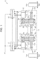
- a turning apparatus 10 includes a housing 11 fixed to a vehicle body (not shown).
- a wheel turning shaft 12 is accommodated inside the housing 11.
- the wheel turning shaft 12 extends along a right and left direction of the vehicle body (right and left direction in FIG. 1 ).
- a first tie rod 14a is coupled to a first end (left end in FIG. 1 ) of the wheel turning shaft 12 via a first inner ball joint 13a.
- a first steered wheel 15a is coupled to an end of the first tie rod 14a across from the first inner ball joint 13a.
- a second tie rod 14b is coupled to a second end (right end in FIG.
- a second steered wheel 15b is coupled to an end of the second tie rod 14b across from the second inner ball joint 13b.
- the wheel turning shaft 12 has a first ball screw groove portion 12a and a second ball screw groove portion 12b.
- the first ball screw groove portion 12a is a portion at which right-hand thread is provided over a predetermined range adjacent to the first end (left end in FIG. 1 ) in the wheel turning shaft 12.
- the second ball screw groove portion 12b is a portion at which left-hand thread is provided over a predetermined range adjacent to the second end (right end in FIG. 1 ) in the wheel turning shaft 12.
- the turning apparatus 10 includes a first ball nut 15 and a second ball nut 16.
- the first ball nut 15 is screwed to the first ball screw groove portion 12a of the wheel turning shaft 12 via a plurality of balls (not shown).
- the second ball nut 16 is screwed to the second ball screw groove portion 12b of the wheel turning shaft 12 via a plurality of balls (not shown).
- the first ball screw groove portion 12a of the wheel turning shaft 12, the balls (not shown), and the first ball nut 15 make up a first ball screw BSi.
- the second ball screw groove portion 12b of the wheel turning shaft 12, the balls (not shown), and the second ball nut 16 make up a second ball screw BS 2 .
- the turning apparatus 10 includes a first motor 17 and a second motor 18.
- the first motor 17 and the second motor 18 are sources that generate a wheel steering force that is a power for turning the first steered wheel 15a and the second steered wheel 15b.
- a three-phase brushless motor is employed as each of the first motor 17 and the second motor 18.
- the first motor 17 and the second motor 18 are respectively fixed to portions outside the housing 11.
- An output shaft 17a of the first motor 17 and an output shaft 18a of the second motor 18 extend parallel to the wheel turning shaft 12.
- the turning apparatus 10 includes a first belt transmission mechanism 21 and a second belt transmission mechanism 22.
- the first belt transmission mechanism 21 includes a drive pulley 23, a driven pulley 24, and an endless belt 25.
- the drive pulley 23 is a synchronous pulley on the outer periphery of which teeth 23a are provided, and is fixed to the output shaft 17a of the first motor 17.
- the driven pulley 24 is a synchronous pulley on the outer periphery of which teeth 24a are provided, and is fixed so as to be fitted to the outer periphery of the first ball nut 15.
- the belt 25 is a synchronous belt on the inner periphery of which teeth 25a are provided, and is wound between the drive pulley 23 and the driven pulley 24. Therefore, rotation of the first motor 17 is transmitted to the first ball nut 15 via the drive pulley 23, the belt 25, and the driven pulley 24.
- the second belt transmission mechanism 22, as well as the first belt transmission mechanism 21, includes a drive pulley 26, a driven pulley 27, and an endless belt 28.
- the drive pulley 26 is a synchronous pulley on the outer periphery of which teeth 26a are provided, and is fixed to the output shaft 18a of the second motor 18.
- the driven pulley 27 is a synchronous pulley on the outer periphery of which teeth 27a are provided, and is fixed so as to be fitted to the outer periphery of the second ball nut 16.
- the belt 28 is a synchronous belt on the inner periphery of which teeth 28a are provided, and is wound between the drive pulley 26 and the driven pulley 27. Therefore, rotation of the second motor 18 is transmitted to the second ball nut 16 via the drive pulley 26, the belt 28, and the driven pulley 27.
- the first belt transmission mechanism 21 and the first ball screw BSi make up a first transmission mechanism that transmits the driving force of the first motor 17 to the wheel turning shaft 12.
- the second belt transmission mechanism 22 and the second ball screw BS 2 make up a second transmission mechanism that transmits the driving force of the second motor 18 to the wheel turning shaft 12.
- a speed reducing ratio from the first motor 17 to the wheel turning shaft 12 (the speed reducing ratio of the first transmission mechanism) and a speed reducing ratio from the second motor 18 to the wheel turning shaft 12 (the speed reducing ratio of the second transmission mechanism) are the same values.
- the lead of the first ball screw groove portion 12a and the lead of the second ball screw groove portion 12b in the wheel turning shaft 12 are the same values. Therefore, the amount of movement of the wheel turning shaft 12 when the first motor 17 makes one revolution and the amount of movement of the wheel turning shaft 12 when the second motor 18 makes one revolution are the same values.
- the turning apparatus 10 includes a first rotation angle sensor 31 and a second rotation angle sensor 32.
- a resolver is employed as each of the first rotation angle sensor 31 and the second rotation angle sensor 32.
- a detection range of the first rotation angle sensor 31 is 360° corresponding to one cycle of an electrical angle of the first motor 17.
- a detection range of the second rotation angle sensor 32 is 360° corresponding to one cycle of an electrical angle of the second motor 18.
- the first rotation angle sensor 31 is attached to the first motor 17.
- the first rotation angle sensor 31 detects a rotation angle (electrical angle) ⁇ of the first motor 17.
- the first rotation angle sensor 31 generates a first sine signal (sin signal) that varies sinusoidally as an electrical signal with rotation of the first motor 17 and a first cosine signal (cos signal) that varies cosinusoidally with rotation of the first motor 17.
- the first rotation angle sensor 31 computes the arc tangent based on the first sine signal and the first cosine signal as the rotation angle ⁇ of the first motor 17.
- the rotation angle ⁇ varies in a sawtooth wave shape at a cycle according to the multiplication factor of angle of the first rotation angle sensor 31. In other words, the rotation angle ⁇ varies in such a manner as to repeat rising and steep falling with rotation of the first motor 17.
- the second rotation angle sensor 32 is attached to the second motor 18.
- the second rotation angle sensor 32 detects a rotation angle (electrical angle) ⁇ of the second motor 18.
- the second rotation angle sensor 32 generates a second sine signal that varies sinusoidally as an electrical signal with rotation of the second motor 18 and a second cosine signal that varies cosinusoidally with rotation of the second motor 18.
- the second rotation angle sensor 32 computes the arc tangent based on the second sine signal and the second cosine signal as the rotation angle ⁇ of the second motor 18.
- the rotation angle ⁇ varies in a sawtooth wave shape at a cycle according to the multiplication factor of angle of the second rotation angle sensor 32.
- the first rotation angle sensor 31 and the second rotation angle sensor 32 have mutually different multiplication factors of angle.
- a multiplication factor of angle means the ratio of an electrical angle of an electrical signal to a rotation angle (mechanical angle) of the first motor 17 or the second motor 18.
- the multiplication factor of angle of the first rotation angle sensor 31 is one (IX).
- the multiplication factor of angle of the first rotation angle sensor 31 is four (4X).
- the first rotation angle sensor 31 and the second rotation angle sensor 32 have mutually different multiplication factors of angle, the number of cycles of the rotation angle ⁇ per one revolution of the first motor 17 and the number of cycles of the rotation angle ⁇ per one revolution of the second motor 18 are different from each other.
- the value of rotation angle (mechanical angle) of the first motor 17 per one cycle of an electrical signal generated by the first rotation angle sensor 31 and the value of rotation angle (mechanical angle) of the second motor 18 per one cycle of an electrical signal generated by the second rotation angle sensor 32 are different from each other.
- the first motor 17 is coupled to the wheel turning shaft 12 and, by extension, the first steered wheel 15a and the second steered wheel 15b via the first belt transmission mechanism 21 and the first ball screw BSi.
- the second motor 18 is coupled to the wheel turning shaft 12 and, by extension, the first steered wheel 15a and the second steered wheel 15b via the second belt transmission mechanism 22 and the second ball screw BS 2 .
- the rotation angle ⁇ of the first motor 17 and the rotation angle ⁇ of the second motor 18 each are a value that reflects an absolute position of the wheel turning shaft 12 in the axial direction and, by extension, the wheel steering angle ⁇ wa of the first steered wheel 15a and the wheel steering angle ⁇ wb of the second steered wheel 15b.
- the turning apparatus 10 includes a first controller 41 and a second controller 42.
- the first controller 41 controls the first motor 17.
- the first controller 41 acquires a target wheel steering angle ⁇ * computed by, for example, an in-vehicle host controller according to a steering status of the vehicle or a travel status of the vehicle.
- the first controller 41 acquires the rotation angle ⁇ of the first motor 17, detected through the first rotation angle sensor 31, and the rotation angle ⁇ of the second motor 18, detected through the second rotation angle sensor 32.
- the first controller 41 executes wheel steering control to turn the first steered wheel 15a and the second steered wheel 15b through drive control over the first motor 17 in accordance with a steering status.
- the first controller 41 computes an actual absolute position of the wheel turning shaft 12 by using the rotation angle ⁇ of the first motor 17, detected through the first rotation angle sensor 31, and the rotation angle ⁇ of the second motor 18, detected through the second rotation angle sensor 32.
- the first controller 41 computes a target absolute position of the wheel turning shaft 12 based on the target wheel steering angle ⁇ *.
- the first controller 41 finds a difference between the target absolute position and actual absolute position of the wheel turning shaft 12 and executes position feedback control for controlling an electric power supplied to the first motor 17 such that the difference is minimized.
- the first controller 41 computes a current command value for the first motor 17 and a current command value for the second motor 18 in accordance with a difference between the target absolute position and actual absolute position of the wheel turning shaft 12 and supplies a current according to the computed current command value to the first motor 17.
- the second controller 42 controls the second motor 18.
- the second controller 42 executes wheel steering control for turning the first steered wheel 15a and the second steered wheel 15b through drive control over the second motor 18 in accordance with a steering status.
- the second controller 42 acquires a current command value computed by the first controller 41 and controls an electric power supplied to the second motor 18 based on the acquired current command value.
- the second controller 42 acquires the target wheel steering angle ⁇ * computed by the host controller as described above, the rotation angle ⁇ of the first motor 17, detected through the first rotation angle sensor 31, and the rotation angle ⁇ of the second motor 18, detected through the second rotation angle sensor 32.
- the second controller 42 has a first function of computing an actual absolute position of the wheel turning shaft 12 by using the rotation angle ⁇ of the first motor 17, detected through the first rotation angle sensor 31, and the rotation angle ⁇ of the second motor 18, detected through the second rotation angle sensor 32.
- the second controller 42 has a second function of computing a target absolute position of the wheel turning shaft 12 based on the target wheel steering angle ⁇ *.
- the second controller 42 has a third function of finding a difference between the target absolute position and actual absolute position of the wheel turning shaft 12 and executing position feedback control for controlling an electric power supplied to the second motor 18 such that the difference is minimized.
- the second controller 42 maintains the first to third functions in a stopped state. In this case, the target wheel steering angle ⁇ *, the rotation angle ⁇ of the first motor 17, and the rotation angle ⁇ of the second motor 18 are not used.
- first ball nut 15 and the second ball nut 16 With rotation of the first ball nut 15 and the second ball nut 16 relative to the wheel turning shaft 12, a torque about the axis is applied to the wheel turning shaft 12.
- the operations of the first motor 17 and the second motor 18 are controlled such that the first ball nut 15 and the second ball nut 16 rotate in opposite directions from each other and the magnitude of torque applied to the wheel turning shaft 12 with rotation of one of the ball nuts is basically the same value as the magnitude of torque applied to the wheel turning shaft 12 with rotation of the other one of the ball nuts.
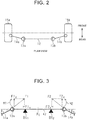
- the end of the first tie rod 14a across from the first inner ball joint 13a is coupled at a position adjacent to the rear side of the vehicle with respect to the rotation center of the first steered wheel 15a when the vehicle travels straight ahead.
- the end of the second tie rod 14b across from the second inner ball joint 13b is coupled at a position adjacent to the rear side of the vehicle with respect to the rotation center of the second steered wheel 15b when the vehicle travels straight ahead.
- Such a link structure is commonly called rear link.
- the first tie rod 14a makes a first inclination ⁇ a with the wheel turning shaft 12.
- the second tie rod 14b makes a second inclination ⁇ b with the wheel turning shaft 12.
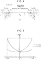
- bending moment M1 is applied to the first ball screw BSi by the radial load F1 z acting on the first end of the wheel turning shaft 12.
- a reverse input load F2 from the second steered wheel 15b is decomposed into an axial load F2X acting in a direction along the axial direction of the wheel turning shaft 12 and a radial load F2 z acting in a direction perpendicular to the axial direction of the wheel turning shaft 12.
- bending moment M2 is applied to the second ball screw BS 2 by the radial load F2 z acting on the second end of the wheel turning shaft 12.
- the value of the bending moment M1 varies according to the first inclination ⁇ a that is an angle formed between the first tie rod 14a and the wheel turning shaft 12 and a distance from the first inner ball joint 13a to the first ball screw BSi.
- the value of the bending moment M2 varies according to the second inclination ⁇ b that is an angle formed between the second tie rod 14b and the wheel turning shaft 12 and a distance from the second inner ball joint 13b to the second ball screw BS 2 .
- the value of the first inclination ⁇ a and the value of the second inclination ⁇ b vary with the wheel steering angle ⁇ wa of the first steered wheel 15a and the wheel steering angle ⁇ wb of the second steered wheel 15b, that is, the position of the wheel turning shaft 12.
- the value of the first inclination ⁇ a increases, the value of the radial load F1 z and, by extension, the value of the bending moment M1 increase.
- the value of the second inclination ⁇ b increases, the value of the radial load F2 z and, by extension, the value of the bending moment M2 increase.
- the first inclination ⁇ a and the second inclination ⁇ b for the absolute position of the wheel turning shaft 12 are different from each other. For this reason, a reverse input load F1 from the first steered wheel 15a and a reverse input load F2 from the second steered wheel 15b are different from each other.
- the direction of the reverse input load F1 from the first steered wheel 15a and the direction of the reverse input load F2 from the second steered wheel 15b are also different from each other.
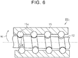
- the wheel turning shaft 12 moves in the axial direction within a maximum movement range Ra determined with respect to the neutral position P 0 corresponding to the straight-ahead direction of the vehicle.
- a first direction (left direction in FIG. 4 ) with respect to the neutral position P 0 of the wheel turning shaft 12 is defined as positive direction.
- a second direction (right direction in FIG. 4 ) with respect to the neutral position P 0 of the wheel turning shaft 12 is defined as negative direction.
- the change characteristics of the first inclination ⁇ a against a position change of the wheel turning shaft 12 with respect to the neutral position Po of the wheel turning shaft 12 and the change characteristics of the second inclination ⁇ b against a position change of the wheel turning shaft 12 with respect to the neutral position Po of the wheel turning shaft 12 are inverse from each other.
- the value of the first inclination ⁇ a gradually increases.
- the value of the first inclination ⁇ a reaches an angle ⁇ 2 ( ⁇ 0 ⁇ ⁇ 1 ⁇ ⁇ 2 ).
- the second inclination ⁇ b is maintained at the angle ⁇ 0 .
- the value of the second inclination ⁇ b gradually increases.
- the value of the second inclination ⁇ b reaches the angle ⁇ 2 ( ⁇ 0 ⁇ ⁇ 2 ).
- the value of the second inclination ⁇ b gradually reduces and then increases.
- the value of the second inclination ⁇ b reaches the angle ⁇ 1 ( ⁇ 0 ⁇ ⁇ 1 ⁇ ⁇ 2 ).
- the first inclination ⁇ a and the second inclination ⁇ b are bilaterally symmetric with respect to the neutral position P 0 . This is because geometrical arrangement of the wheel turning shaft 12, the first tie rod 14a, the second tie rod 14b, the first steered wheel 15a, and the second steered wheel 15b is bilaterally symmetric.
- the value of the bending moment M1 is obtained by multiplying the value of the radial load F1 z acting on the wheel turning shaft 12 and a distance from the first inner ball joint 13a to the first ball screw BSi. For this reason, as the value of the first inclination ⁇ a increases and the value of the radial load F1 z acting on the wheel turning shaft 12 increases, or as a distance from the first inner ball joint 13a to the first ball screw BS 1 extends, the value of the bending moment M1 increases.
- the value of the bending moment M2 is obtained by multiplying the value of the radial load F2 z acting on the wheel turning shaft 12 and a distance from the second inner ball joint 13b to the second ball screw BS 2 . For this reason, as the value of the second inclination ⁇ b increases and the value of the radial load F2 z acting on the wheel turning shaft 12 increases, or as a distance from the second inner ball joint 13b to the second ball screw BS 2 extends, the value of the bending moment M2 increases. When such radial loads F1 z , F2 z and, by extension, the bending moments M1, M2, are applied to the wheel turning shaft 12, there are concerns about the following situations.
- the wheel turning shaft 12 may be slightly bent or inclined about a portion where the first ball screw BSi is provided depending on the magnitude of the bending moment M1.
- a load concentrates on balls 15c or part of the first ball screw groove portion 12a (a screw groove portion where the part of the balls 15c contact) in the first ball screw BSi.
- the product service life of the first ball screw BSi may decrease.
- smooth operation of the first ball screw BSi may be impaired.
- the product service life of the second ball screw BS 2 may decrease as in the case where the radial load F1 z or the bending moment M1 is applied to the wheel turning shaft 12 via the first tie rod 14a. Also, smooth operation of the second ball screw BS 2 may be impaired.
- the following components are employed as the first controller 41 and the second controller 42.
- the first controller 41 includes a position detection circuit 51, a position control circuit 52, an allocation computing circuit 53, a multiplier 54, a current control circuit 55, and a subtractor 56.
- the position detection circuit 51 acquires the rotation angle ⁇ of the first motor 17, detected through the first rotation angle sensor 31, and the rotation angle ⁇ of the second motor 18, detected through the second rotation angle sensor 32, and computes the absolute position P1 of the wheel turning shaft 12 based on the acquired rotation angles ⁇ , ⁇ .
- the multiplication factor of angle of the first rotation angle sensor 31 and the multiplication factor of angle of the second rotation angle sensor 32 are set such that the rotation angle ⁇ detected by the first rotation angle sensor 31 and the rotation angle ⁇ detected by the second rotation angle sensor 32 do not coincide with each other within the maximum movement range of the wheel turning shaft 12. For this reason, a combination of the value of the rotation angle ⁇ and the value of the rotation angle ⁇ is in a one-to-one correspondence with the absolute position P1 of the wheel turning shaft 12. Therefore, it is possible to immediately detect the absolute position P1 of the wheel turning shaft 12 based on a combination of the two rotation angles ⁇ , ⁇ .
- the position control circuit 52 computes the target absolute position of the wheel turning shaft 12 based on the target wheel steering angle ⁇ * computed by the host controller. Since the wheel turning shaft 12 is interlocked with the steered wheels 15a, 15b, there is a correlation between an absolute position of the wheel turning shaft 12 and each of the wheel steering angles ⁇ wa, ⁇ wb of the steered wheels 15a, 15b. The target absolute position of the wheel turning shaft 12 is obtained from the target wheel steering angle ⁇ * by using the correlation.
- the position control circuit 52 finds a difference between the target absolute position of the wheel turning shaft 12 and an actual absolute position P1 of the wheel turning shaft 12, computed by the position detection circuit 51, and computes a current command value I* for the first motor 17 and the second motor 18 such that the difference is minimized.
- the current command value I* corresponds to a total torque to be generated by the first motor 17 and the second motor 18.
- the allocation computing circuit 53 acquires the rotation angle ⁇ of the first motor 17, detected through the first rotation angle sensor 31, and the rotation angle ⁇ of the second motor 18, detected through the second rotation angle sensor 32, and computes the absolute position Ps of the wheel turning shaft 12 based on the acquired rotation angles ⁇ , ⁇ .
- the allocation computing circuit 53 computes a first allocation rate DR 1 , for the first motor 17, of the current command value I* computed by the position control circuit 52, based on a current value of the computed absolute position Ps of the wheel turning shaft 12.
- the first allocation rate DR 1 is set to a value that falls within the range greater than or equal to "0" and less than or equal to "1".
- the allocation computing circuit 53 computes a first allocation rate DR 1 by using a map that defines the relationship between an absolute position Ps of the wheel turning shaft 12 and a first allocation rate DR 1 .
- the map is stored in a storage device of the first controller 41.
- a map M p is a two-dimensional map of which the abscissa axis represents the absolute position Ps of the wheel turning shaft 12 and the ordinate axis represents the first allocation rate DR 1 and has the following characteristics.
- the first allocation rate DR 1 gradually increases within the maximum movement range Ra of the wheel turning shaft 12 as the absolute position Ps of the wheel turning shaft 12 changes from the negative maximum position -P max via the neutral position P 0 toward the positive maximum position +P max .
- the first allocation rate DR1 is "0.5". This is a value corresponding to 50% where the current command value I* computed by the position control circuit 52 is 100%.
- the map M p is set through, for example, simulations.
- the absolute position Ps of the wheel turning shaft 12 is varied, the reverse input load F1 from the first steered wheel 15a and the reverse input load F2 from the second steered wheel 15b at each absolute position Ps of the wheel turning shaft 12 are obtained.
- the absolute position Ps of the wheel turning shaft 12 is varied, the first inclination ⁇ a of the first tie rod 14a and the second inclination ⁇ b of the second tie rod 14b at each absolute position Ps of the wheel turning shaft 12 are obtained.
- a bending moment M1 applied to the first ball screw BSi and a bending moment M2 applied to the second ball screw BS 2 and, by extension, contact pressures applied to the balls of the first ball screw BS 1 and the second ball screw BS 2 are obtained based on the obtained values of the reverse input loads F1, F2 and the obtained values of the first inclination ⁇ a and the second inclination ⁇ b at each absolute position Ps of the wheel turning shaft 12.
- the map M p is set through adaptation of the value of the first allocation rate DR 1 and the value of the second allocation rate DR 2 for the absolute position Ps of the wheel turning shaft 12.
- the multiplier 54 computes a first current command value I 1 * for the first motor 17 by multiplying the first allocation rate DR 1 computed by the allocation computing circuit 53 by the current command value I* computed by the position control circuit 52.
- the current control circuit 55 supplies the first motor 17 with an electric power according to the first current command value I 1 * computed by the multiplier 54.
- the first motor 17 generates a torque according to the first current command value I 1 *.
- the subtractor 56 computes a second allocation rate DR 2 , for the second motor 18, of the current command value I* by subtracting the first allocation rate DRi computed by the allocation computing circuit 53 from "1" that is a fixed value stored in the storage device of the first controller 41. For example, when the first allocation rate DRi is set to "0.3", the value of the second allocation rate DR 2 is "0.7". When the first allocation rate DR 1 is set to "0.5”, the value of the second allocation rate DR 2 is "0.5”. When the first allocation rate DR 1 is set to "0.7”, the value of the second allocation rate DR 2 is "0.3". In other words, a total value of torque generated by the first motor 17 and the second motor 18 is a torque according to the current command value I* computed by the position control circuit 52.
- the change characteristics of the second allocation rate DR 2 against a change in the absolute position Ps of the wheel turning shaft 12 are inverse to the change characteristics of the first allocation rate DR 1 against a change in the absolute position Ps of the wheel turning shaft 12.
- the first allocation rate DR 1 gradually reduces and the second allocation rate DR 2 gradually increases as the absolute position Ps of the wheel turning shaft 12 moves from the positive maximum position +P max via the neutral position Po toward the negative maximum position -P max .
- the value of the second allocation rate DR 2 when the absolute position Ps of the wheel turning shaft 12 is the positive maximum position +P max and the value of the first allocation rate DR 1 when the absolute position Ps of the wheel turning shaft 12 is the negative maximum position -P max are equal to each other.
- the value of the second allocation rate DR 2 when the absolute position Ps of the wheel turning shaft 12 is the negative maximum position -P max and the value of the first allocation rate DRi when the absolute position Ps of the wheel turning shaft 12 is the positive maximum position +P max are equal to each other.
- the first allocation rate DRi and the second allocation rate DR 2 are set so as to be symmetric with respect to the neutral position Po (ordinate axis) of the wheel turning shaft 12 and have mutually inverse characteristics.
- the second controller 42 includes a position detection circuit 61, a position control circuit 62, a multiplier 63, and a current control circuit 64.
- the position detection circuit 61 acquires the rotation angle ⁇ of the first motor 17, detected through the first rotation angle sensor 31, and the rotation angle ⁇ of the second motor 18, detected through the second rotation angle sensor 32, and computes the absolute position P2 of the wheel turning shaft 12 based on the acquired rotation angles ⁇ , ⁇ .
- the position detection circuit 61 is used as a backup for the first controller 41, and the functions of the position detection circuit 61 are maintained in a stopped state under a normal condition in which the first controller 41 is operating normally.
- the position control circuit 62 computes the target absolute position of the wheel turning shaft 12 based on the target wheel steering angle ⁇ * computed by the host controller.
- the position control circuit 62 finds a difference between the target absolute position of the wheel turning shaft 12 and an actual absolute position P2 of the wheel turning shaft 12, computed by the position detection circuit 61, and computes a current command value I* according to a total torque to be generated by the first motor 17 and the second motor 18 such that the difference is minimized.
- the position control circuit 62 is used as a backup for the first controller 41, and the functions of the position control circuit 62 are maintained in a stopped state under a normal condition in which the first controller 41 is operating normally.
- the multiplier 63 computes a second current command value I 2 * for the second motor 18 by multiplying the second allocation rate DR 2 computed by the subtractor 56 of the first controller 41 by the current command value I* computed by the position control circuit 52 of the first controller 41.
- the current control circuit 64 supplies the second motor 18 with an electric power according to the second current command value I 2 * computed by the multiplier 63.
- the second motor 18 generates a torque according to the second current command value I 2 *.
- the first tie rod 14a is provided at the first inclination ⁇ a with respect to the wheel turning shaft 12.
- the second tie rod 14b is provided at the second inclination ⁇ b with respect to the wheel turning shaft 12. For this reason, as the wheel turning shaft 12 approaches the negative maximum position -P max or the positive maximum position +P max with respect to the neutral position P 0 , the first inclination ⁇ a of the first tie rod 14a and the second inclination ⁇ b of the second tie rod 14b with respect to the wheel turning shaft 12 increase.
- the value of the first inclination ⁇ a increases, the value of the radial load F1 z and, by extension, the value of the bending moment M1, applied to the wheel turning shaft 12, increase.
- the value of the second inclination ⁇ b increases, the value of the radial load F2 z and, by extension, the value of the bending moment M2, applied to the wheel turning shaft 12, increase.
- the first inclination ⁇ a and the second inclination ⁇ b with respect to the absolute position Ps of the wheel turning shaft 12 are mutually different values. For this reason, the values of the radial loads F1 z , F2 z and, by extension, the values of bending moments M1, M2, applied to the wheel turning shaft 12, are also mutually different values.
- the torque of the motor 17 associated with the ball screw BS 1 or the torque of the motor 18 associated with the ball screw BS 2 , on a side where a larger one of the radial loads F1 z , F2 z is applied is more reduced, while the torque of the motor associated with the ball screw on a side where a smaller one of the radial loads is applied is more increased.
- the torque of the motor associated with the ball screw on a side where a larger one of the bending moments M1, M2 is applied is reduced, while the torque of the motor associated with the ball screw on a side where a smaller one of the bending moments is applied is increased.
- the value of the first inclination ⁇ a that is an angle formed between the first tie rod 14a and the wheel turning shaft 12 and the value of the second inclination ⁇ b that is an angle formed between the second tie rod 14b and the wheel turning shaft 12 vary with the position of the wheel turning shaft 12.
- the first inclination ⁇ a and the second inclination ⁇ b take different values for the position of the wheel turning shaft 12, and the magnitudes of the radial loads F1 z , F2 z that are applied to the wheel turning shaft 12 vary with the first inclination ⁇ a and the second inclination ⁇ b .
- the torque of the motor associated with the ball screw on a side where a smaller one of the radial loads is applied is increased by the amount by which the torque of the motor associated with the ball screw on a side where a larger one of the radial loads is applied is reduced.
- the first motor 17 and the second motor 18 are capable of generating a torque according to the current command value I* in total. For this reason, while a total torque generated by the first motor 17 and the second motor 18 is ensured, it is possible to protect the first ball screw BS 1 and the second ball screw BS 2 .
- the torque of the motor associated with the ball screw to which a larger one of the radial loads is applied is reduced, while the torque of the motor associated with the ball screw to which a smaller one of the radial loads is applied is increased.
- the change characteristics of the first inclination ⁇ a against a position change of the wheel turning shaft 12 with respect to the neutral position P 0 of the wheel turning shaft 12 and the change characteristics of the second inclination ⁇ b against a position change of the wheel turning shaft 12 with respect to the neutral position P 0 of the wheel turning shaft 12 are inverse from each other.
- the change characteristics of the bending moment M1 about the first ball screw BS 1 against a position change of the wheel turning shaft 12 with respect to the neutral position P 0 of the wheel turning shaft 12 and the change characteristics of the bending moment M2 about the second ball screw BS 2 against a position change of the wheel turning shaft 12 with respect to the neutral position Po of the wheel turning shaft 12 are also inverse from each other. For this reason, it is easy to adjust the first allocation rate DR 1 for the first motor 17 associated with the first ball screw BS 1 and the second allocation rate DR 2 for the second motor 18 associated with the second ball screw BS 2 .
- the turning apparatus 10 has such characteristics that, as the wheel turning shaft 12 moves with respect to the neutral position P 0 , the value of moment about the ball screw located on a side across from a side to which the wheel turning shaft 12 moves increases. For example, as the wheel turning shaft 12 moves in the negative direction (right direction in FIG. 4 ) with respect to the neutral position P 0 , the value of the bending moment M1 about the first ball screw BSi located on a side (left side in FIG.
- the first controller 41 more reduces the allocation rate of the current command value I* for the motor associated with the ball screw on a side across from the side to which the wheel turning shaft 12 moves and more increases the allocation rate of the current command value I* for the motor associated with the ball screw on the side to which the wheel turning shaft 12 moves.
- the first allocation rate DR 1 for the first motor 17 and the second allocation rate DR 2 for the second motor 18 are further appropriately set according to the position of the wheel turning shaft 12. Therefore, it is possible to further minutely adjust a load on the motion of the first ball screw BS 1 and a load on the motion of the second ball screw BS 2 according to the position of the wheel turning shaft 12.
- a current supplied to the first motor 17 and a current supplied to the second motor 18 are determined by the first controller 41.
- the second controller 42 just operates to supply the second motor 18, which is an object to be controlled by the second controller 42, with a current according to an individual current command value (I 2 *) based on the second allocation rate DR 2 unilaterally determined by the first controller 41.
- the first controller 41 and the second controller 42 are in a relation of master machine and slave machine.
- the first controller 41 and the second controller 42 each individually compute a current command value for the motor, which is an object to be controlled by a corresponding one of the controllers 41, 42, by executing position control and control an electric power supplied to the motor, which is the object to be controlled, based on the individually computed current command value, interference between control of the first controller 41 and control of the second controller 42 is suppressed.
- Such interference between position feedback control over the wheel turning shaft 12 by the first controller 41 and position feedback control over the wheel turning shaft 12 by the second controller 42 does not occur due to, for example, a lead error between the first ball screw groove portion 12a and second ball screw groove portion 12b of the wheel turning shaft 12, or the like. Therefore, the first motor 17 and the second motor 18 appropriately operate in cooperation with each other, so it is possible to further appropriately turn the first steered wheel 15a and the second steered wheel 15b.
- the present embodiment basically has similar components to those of the first embodiment.
- the present embodiment differs from the first embodiment in a coupling position of each tie rod to the associated steered wheel.
- the end of the first tie rod 14a across from the first inner ball joint 13a is coupled at a position adjacent to the front side of the vehicle with respect to the rotation center of the first steered wheel 15a when the vehicle travels straight ahead.
- the end of the second tie rod 14b across from the second inner ball joint 13b is coupled at a position adjacent to the front side of the vehicle with respect to the rotation center of the second steered wheel 15b when the vehicle travels straight ahead.
- the change characteristics of each of the first inclination ⁇ a and the second inclination ⁇ b against the absolute position Ps of the wheel turning shaft 12 are inverse to those of the rear link.
- the first inclination ⁇ a is maintained at the angle ⁇ 0 .
- the value of the first inclination ⁇ a gradually increases.
- the value of the first inclination ⁇ a reaches the angle ⁇ 2 ( ⁇ 0 ⁇ ⁇ 2 ).
- the value of the first inclination ⁇ a gradually reduces and then increases.
- the value of the first inclination ⁇ a reaches the angle ⁇ 1 ( ⁇ 0 ⁇ ⁇ 1 ⁇ ⁇ 2 ).
- the second inclination ⁇ b is maintained at the angle ⁇ 0 .
- the value of the second inclination ⁇ b gradually reduces and then increases.
- the value of the second inclination ⁇ b reaches the angle ⁇ 1 ( ⁇ 0 ⁇ ⁇ 1 ).
- the value of the second inclination ⁇ b gradually increases.
- the value of the second inclination ⁇ b reaches the angle ⁇ 2 ( ⁇ 0 ⁇ ⁇ 1 ⁇ ⁇ 2 ).
- the first allocation rate DRi gradually increases within the maximum movement range Ra of the wheel turning shaft 12 as the absolute position Ps of the wheel turning shaft 12 changes from the positive maximum position +P max via the neutral position Po toward the negative maximum position -P max .
- the second allocation rate DR 2 gradually increases within the maximum movement range Ra of the wheel turning shaft 12 as the absolute position Ps of the wheel turning shaft 12 changes from the negative maximum position -P max via the neutral position Po toward the positive maximum position +P max .
- the value of the first allocation rate DR 1 when the absolute position Ps of the wheel turning shaft 12 is the positive maximum position +P max and the value of the second allocation rate DR 2 when the absolute position Ps of the wheel turning shaft 12 is the negative maximum position -P max are equal to each other.
- the value of the first allocation rate DR 1 when the absolute position Ps of the wheel turning shaft 12 is the negative maximum position -P max and the value of the second allocation rate DR 2 when the absolute position Ps of the wheel turning shaft 12 is the positive maximum position +P max are equal to each other.
- the first allocation rate DRi and the second allocation rate DR 2 are set so as to be symmetric with respect to the neutral position Po (ordinate axis) of the wheel turning shaft 12 and have mutually inverse characteristics.
- the change characteristics of each of the first inclination ⁇ a and the second inclination ⁇ b against a change in the absolute position Ps of the wheel turning shaft 12 are inverse to the change characteristics shown in FIG. 5 .
- the turning apparatus 10 has such characteristics that, as the wheel turning shaft 12 moves with respect to the neutral position P 0 , the value of moment about the ball screw located on a side to which the wheel turning shaft 12 moves increases.
- the value of the bending moment M2 about the second ball screw BS 2 located on a side (right side in FIG. 4 ) to which the wheel turning shaft 12 moves increases.
- the value of the bending moment M1 about the first ball screw BS 1 located on a side (left side in FIG. 4 ) to which the wheel turning shaft 12 moves increases.
- the first controller 41 more reduces the allocation rate of the current command value I* for the motor associated with the ball screw on a side to which the wheel turning shaft 12 moves and more increases the allocation rate of the current command value I* for the motor associated with the ball screw on a side across from the side to which the wheel turning shaft 12 moves.
- first and second embodiments may be modified as follows.
- the first allocation rate DR 1 when the wheel turning shaft 12 is located at the neutral position P 0 , the first allocation rate DR 1 , for the first motor 17, of the current command value I* is set to "0.5"; however, the configuration is not limited thereto.
- the first allocation rate DR 1 when the wheel turning shaft 12 is located at the neutral position P 0 may be set to an appropriate value such as "0.6" or "0.4" according to product specifications.
- the first allocation rate DRi can be set to "0.6”
- the second allocation rate DR 2 is "0.4”.
- the first allocation rate DRi can be set to "0.4”
- the second allocation rate DR 2 is "0.6".
- the first ball screw groove portion 12a may be formed as left-hand thread
- the second ball screw groove portion 12b may be formed as right-hand thread.
- the first ball screw groove portion 12a and the second ball screw groove portion 12b just need to have an opposite thread relation.
- both the first ball screw groove portion 12a and the second ball screw groove portion 12b may be formed as right-hand thread or left-hand thread.
- the wheel turning shaft 12 includes a rotation restriction portion for suppressing rotation of the wheel turning shaft 12 relative to the housing 11.
- the allocation computing circuit 53 may compute a first allocation rate DR 1 by using the absolute position P1 of the wheel turning shaft 12, computed by the first controller 41, or the absolute position P2 of the wheel turning shaft 12, computed by the second controller 42. With this configuration, it is possible to reduce the computation load of the allocation computing circuit 53 by the amount by which the allocation computing circuit 53 does not need to compute the absolute position Ps of the wheel turning shaft 12.
- the in-vehicle host controller may be configured not to compute the target wheel steering angle ⁇ *, and may be configured to compute a target absolute position of the wheel turning shaft 12 according to a steering status of the vehicle or a travel status of the vehicle.
- the first controller 41 and the second controller 42 acquire the target absolute position of the wheel turning shaft 12, computed by the host controller, and control an electric power supplied to the first motor 17 and an electric power supplied to the second motor 18 by using the acquired target absolute position.
- the first controller 41 may compute a target rotation angle of the first motor 17 based on the target wheel steering angle ⁇ *, find a difference between the computed target rotation angle of the first motor 17 and the rotation angle ⁇ of the first motor 17, detected through the first rotation angle sensor 31, and control an electric power supplied to the first motor 17 such that the difference is minimized.
- the second controller 42 may compute a target rotation angle of the second motor 18 based on the target wheel steering angle ⁇ *, find a difference between the computed target rotation angle of the second motor 18 and the rotation angle ⁇ of the second motor 18, detected through the second rotation angle sensor 32, and control an electric power supplied to the second motor 18 such that the difference is minimized.
- first and second embodiments a configuration in which the first belt transmission mechanism 21 serving as a first transmission mechanism that transmits the driving force of the first motor 17 to the wheel turning shaft 12 is omitted may be employed, and a configuration in which the second belt transmission mechanism 22 serving as a second transmission mechanism that transmits the driving force of the second motor 18 to the wheel turning shaft 12 is omitted may be employed.
- the first motor 17 and the second motor 18 are provided coaxially with the wheel turning shaft 12.
- the output shaft 17a of the first motor 17 is coupled to the first ball nut 15 so as to be integrally rotatable
- the output shaft 18a of the second motor 18 is coupled to the second ball nut 16 so as to be integrally rotatable.
- components corresponding to the allocation computing circuit 53 and the subtractor 56 may be provided not only in the first controller 41 but also in the second controller 42.
- the second controller 42 has the same configuration as the configuration of the first controller 41 and is able to be used as a backup device for the first controller 41.
- the allocation computing circuit of the second controller 42 computes a second allocation rate DR 2 , for the second motor 18, of the current command value I* computed by the position control circuit 62.
- the subtractor of the second controller 42 computes a first allocation rate DR 1 , for the first motor 17, of the current command value I* by subtracting the second allocation rate DR 2 computed by the allocation computing circuit of the second controller 42 from "1" that is a fixed value stored in the storage device of the second controller 42.
- the allocation computing circuit and subtractor of the second controller 42 are used as a backup for the first controller 41, and the functions of the allocation computing circuit and subtractor are maintained in a stopped state when the first controller 41 is operating normally.
- a configuration in which the position detection circuit 61 and the position control circuit 62 are omitted may be employed as the second controller 42.
- the configuration of the second controller 42 is simplified.
- first controller 41 and the first motor 17 may be provided integrally.
- second controller 42 and the second motor 18 may be provided integrally.
- the turning apparatus 10 in each of the first and second embodiments may be applied to a steer-by-wire steering system in which power transmission between a steering wheel and a wheel turning shaft are separated.
- the steer-by-wire steering system includes a reaction motor that is a source for generating a steering reaction applied to a steering shaft and a reaction controller that controls the drive of the reaction motor, and may include a reaction controller that computes a target steering angle of the steering wheel based on a steering status of the vehicle or a travel status of the vehicle.
- the first controller 41 and the second controller 42 may be configured to acquire a target steering angle computed by, for example, the reaction controller serving as a host controller, as a target wheel steering angle ⁇ *.
- the turning apparatus 10 may be applied to an electric power steering system in which a steering wheel and a wheel turning shaft are connected by a steering shaft and a rack and pinion mechanism.
- the turning apparatus 10 may be configured as a right and left independent turning apparatus that turns the first steered wheel 15a and the second steered wheel 15b independently of each other.
- a configuration including a first wheel turning shaft in which the first ball screw BS 1 is provided and a second wheel turning shaft in which the second ball screw BS 2 is provided is employed as a turning apparatus.
Landscapes
- Engineering & Computer Science (AREA)
- Chemical & Material Sciences (AREA)
- Combustion & Propulsion (AREA)
- Transportation (AREA)
- Mechanical Engineering (AREA)
- Power Steering Mechanism (AREA)
- Steering Control In Accordance With Driving Conditions (AREA)
Applications Claiming Priority (1)
| Application Number | Priority Date | Filing Date | Title |
|---|---|---|---|
| JP2020012577A JP7322725B2 (ja) | 2020-01-29 | 2020-01-29 | 転舵装置 |
Publications (2)
| Publication Number | Publication Date |
|---|---|
| EP3858708A1 true EP3858708A1 (de) | 2021-08-04 |
| EP3858708B1 EP3858708B1 (de) | 2022-08-17 |
Family
ID=74236126
Family Applications (1)
| Application Number | Title | Priority Date | Filing Date |
|---|---|---|---|
| EP21153392.2A Active EP3858708B1 (de) | 2020-01-29 | 2021-01-26 | Lenkvorrichtung |
Country Status (4)
| Country | Link |
|---|---|
| US (1) | US11639191B2 (de) |
| EP (1) | EP3858708B1 (de) |
| JP (1) | JP7322725B2 (de) |
| CN (1) | CN113184043A (de) |
Families Citing this family (3)
| Publication number | Priority date | Publication date | Assignee | Title |
|---|---|---|---|---|
| JP7234962B2 (ja) * | 2020-02-11 | 2023-03-08 | トヨタ自動車株式会社 | 転舵装置およびそれが設けられたステアリングシステム |
| US20230399046A1 (en) * | 2022-06-10 | 2023-12-14 | Zf Active Safety And Electronics Us Llc | Apparatus for use in turning steerable vehicle wheels |
| CN115743290A (zh) * | 2022-12-02 | 2023-03-07 | 质子汽车科技有限公司 | 一种车辆的电动转向系统及车辆 |
Citations (2)
| Publication number | Priority date | Publication date | Assignee | Title |
|---|---|---|---|---|
| JPH0129224B2 (de) | 1980-12-08 | 1989-06-08 | Yunaitetsudo Suteetsu Boratsukusu Ando Chem Corp | |
| JP6429224B1 (ja) * | 2018-05-21 | 2018-11-28 | 株式会社ショーワ | 操舵装置の設計方法 |
Family Cites Families (21)
| Publication number | Priority date | Publication date | Assignee | Title |
|---|---|---|---|---|
| DE19947265A1 (de) | 1999-01-22 | 2000-07-27 | Mercedes Benz Lenkungen Gmbh | Fehlertolerante Kraftfahrzeuglenkung mit autonomem Lenkeingriff |
| US6691819B2 (en) * | 2001-09-17 | 2004-02-17 | Delphi Technologies, Inc. | Actuator for active front wheel steering system |
| JP2004074831A (ja) * | 2002-08-09 | 2004-03-11 | Honda Motor Co Ltd | 電動パワーステアリング装置 |
| JP4100106B2 (ja) * | 2002-09-10 | 2008-06-11 | 日産自動車株式会社 | 車両用操舵制御装置 |
| CN100436227C (zh) * | 2003-10-02 | 2008-11-26 | 日产自动车株式会社 | 车辆转向装置 |
| JP2005161997A (ja) | 2003-12-02 | 2005-06-23 | Nissan Motor Co Ltd | 車両用操舵装置 |
| JP2005329784A (ja) * | 2004-05-19 | 2005-12-02 | Hitachi Ltd | 電動パワーステアリング装置 |
| US7500537B2 (en) * | 2004-08-25 | 2009-03-10 | Toyota Jidosha Kabushiki Kaisha | Steering apparatus for vehicle |
| US20060278466A1 (en) * | 2005-06-13 | 2006-12-14 | Bo Cheng | Electric power steering systems |
| JP5293136B2 (ja) | 2008-12-12 | 2013-09-18 | 株式会社ジェイテクト | 車両用操舵装置 |
| JP2010030368A (ja) * | 2008-07-25 | 2010-02-12 | Nsk Ltd | 車両用操舵装置 |
| KR101126248B1 (ko) * | 2009-12-03 | 2012-03-20 | 현대자동차주식회사 | 스티어 바이 와이어 장치 |
| EP2681098B1 (de) * | 2011-03-04 | 2017-05-03 | ThyssenKrupp Presta AG | Lenksystem mit überlastschutz |
| DE102012021436A1 (de) * | 2012-10-30 | 2014-04-30 | Volkswagen Aktiengesellschaft | Vorrichtung zum assistierenden oder automatischen Führen eines Kraftfahrzeuges |
| DE112013006263T5 (de) * | 2012-12-28 | 2015-10-08 | Honda Motor Co., Ltd. | Fahrzeuglenkvorrichtung |
| ITTO20130066A1 (it) * | 2013-01-28 | 2014-07-29 | Fiat Group Automobiles Spa | Sistema di servosterzo elettrico per un autoveicolo |
| DE102015116937B4 (de) | 2015-10-06 | 2018-10-31 | Robert Bosch Automotive Steering Gmbh | Verfahren zum Betreiben eines Lenksystems eines Kraftfahrzeugs |
| JP2018020743A (ja) * | 2016-08-05 | 2018-02-08 | 株式会社ジェイテクト | 車両用操舵装置 |
| JP6790572B2 (ja) * | 2016-08-12 | 2020-11-25 | 株式会社ジェイテクト | ステアリング装置 |
| KR20190001964A (ko) | 2017-06-28 | 2019-01-08 | 현대자동차주식회사 | 차량용 조향 장치 및 그 제어 방법 |
| EP3792149B1 (de) * | 2019-08-22 | 2023-09-27 | Jtekt Corporation | Lenkvorrichtung und lenkverfahren |
-
2020
- 2020-01-29 JP JP2020012577A patent/JP7322725B2/ja active Active
-
2021
- 2021-01-22 US US17/155,170 patent/US11639191B2/en active Active
- 2021-01-26 CN CN202110109578.0A patent/CN113184043A/zh active Pending
- 2021-01-26 EP EP21153392.2A patent/EP3858708B1/de active Active
Patent Citations (3)
| Publication number | Priority date | Publication date | Assignee | Title |
|---|---|---|---|---|
| JPH0129224B2 (de) | 1980-12-08 | 1989-06-08 | Yunaitetsudo Suteetsu Boratsukusu Ando Chem Corp | |
| JP6429224B1 (ja) * | 2018-05-21 | 2018-11-28 | 株式会社ショーワ | 操舵装置の設計方法 |
| DE112018007643T5 (de) * | 2018-05-21 | 2021-04-01 | Showa Corporation | Lenkeinrichtung |
Also Published As
| Publication number | Publication date |
|---|---|
| JP2021116032A (ja) | 2021-08-10 |
| EP3858708B1 (de) | 2022-08-17 |
| US11639191B2 (en) | 2023-05-02 |
| CN113184043A (zh) | 2021-07-30 |
| JP7322725B2 (ja) | 2023-08-08 |
| US20210229736A1 (en) | 2021-07-29 |
Similar Documents
| Publication | Publication Date | Title |
|---|---|---|
| EP3858708B1 (de) | Lenkvorrichtung | |
| US4800975A (en) | Motor control unit for electrically operated power steering devices | |
| EP2019020B1 (de) | Servolenkvorrichtung mit Fehlererkennungseinrichtung für Drehwinkelsensoren | |
| CN100562454C (zh) | 电动转向设备及其控制方法 | |
| CN111114626B (zh) | 用于转向装置的控制器 | |
| JP6584877B2 (ja) | 電動ブレーキシステム | |
| CN101722981A (zh) | 车辆用转向装置 | |
| US11427246B2 (en) | Steering system | |
| CN104228936A (zh) | 转向控制器 | |
| CN105416388A (zh) | 电动动力转向装置 | |
| CN111942461B (zh) | 马达控制装置 | |
| CN112550439B (zh) | 转向控制装置 | |
| JP4941723B2 (ja) | 車両用操舵装置 | |
| CN113443005A (zh) | 转向控制装置 | |
| EP3674175A1 (de) | Steuerungsvorrichtung für ein fahrzeug | |
| US12384453B2 (en) | Dual motor drive assembly | |
| US11001246B2 (en) | Electric brake device | |
| CN116729471A (zh) | 转向控制装置 | |
| JP7259495B2 (ja) | 操舵制御装置 | |
| US11066101B2 (en) | Steering control device | |
| JP2016121876A (ja) | 車両用回転角検出装置 | |
| JP7567201B2 (ja) | 転舵装置 | |
| US12503153B2 (en) | Steering control device and steering control method | |
| WO2016047481A1 (ja) | 電動ブレーキシステム | |
| US20240051596A1 (en) | Dual motor drive assembly |
Legal Events
| Date | Code | Title | Description |
|---|---|---|---|
| PUAI | Public reference made under article 153(3) epc to a published international application that has entered the european phase |
Free format text: ORIGINAL CODE: 0009012 |
|
| STAA | Information on the status of an ep patent application or granted ep patent |
Free format text: STATUS: THE APPLICATION HAS BEEN PUBLISHED |
|
| AK | Designated contracting states |
Kind code of ref document: A1 Designated state(s): AL AT BE BG CH CY CZ DE DK EE ES FI FR GB GR HR HU IE IS IT LI LT LU LV MC MK MT NL NO PL PT RO RS SE SI SK SM TR |
|
| STAA | Information on the status of an ep patent application or granted ep patent |
Free format text: STATUS: REQUEST FOR EXAMINATION WAS MADE |
|
| 17P | Request for examination filed |
Effective date: 20211125 |
|
| RBV | Designated contracting states (corrected) |
Designated state(s): AL AT BE BG CH CY CZ DE DK EE ES FI FR GB GR HR HU IE IS IT LI LT LU LV MC MK MT NL NO PL PT RO RS SE SI SK SM TR |
|
| RAP3 | Party data changed (applicant data changed or rights of an application transferred) |
Owner name: JTEKT CORPORATION |
|
| GRAP | Despatch of communication of intention to grant a patent |
Free format text: ORIGINAL CODE: EPIDOSNIGR1 |
|
| STAA | Information on the status of an ep patent application or granted ep patent |
Free format text: STATUS: GRANT OF PATENT IS INTENDED |
|
| INTG | Intention to grant announced |
Effective date: 20220414 |
|
| GRAS | Grant fee paid |
Free format text: ORIGINAL CODE: EPIDOSNIGR3 |
|
| GRAA | (expected) grant |
Free format text: ORIGINAL CODE: 0009210 |
|
| STAA | Information on the status of an ep patent application or granted ep patent |
Free format text: STATUS: THE PATENT HAS BEEN GRANTED |
|
| AK | Designated contracting states |
Kind code of ref document: B1 Designated state(s): AL AT BE BG CH CY CZ DE DK EE ES FI FR GB GR HR HU IE IS IT LI LT LU LV MC MK MT NL NO PL PT RO RS SE SI SK SM TR |
|
| RIN1 | Information on inventor provided before grant (corrected) |
Inventor name: NAKAMURA, KEISHI Inventor name: KONDO, YOSHIO Inventor name: KISHIDA, FUMIO Inventor name: OGATA, TOSHIAKI |
|
| REG | Reference to a national code |
Ref country code: CH Ref legal event code: EP |
|
| REG | Reference to a national code |
Ref country code: DE Ref legal event code: R096 Ref document number: 602021000311 Country of ref document: DE |
|
| REG | Reference to a national code |
Ref country code: IE Ref legal event code: FG4D |
|
| REG | Reference to a national code |
Ref country code: AT Ref legal event code: REF Ref document number: 1511996 Country of ref document: AT Kind code of ref document: T Effective date: 20220915 |
|
| REG | Reference to a national code |
Ref country code: NL Ref legal event code: MP Effective date: 20220817 |
|
| REG | Reference to a national code |
Ref country code: LT Ref legal event code: MG9D |
|
| PG25 | Lapsed in a contracting state [announced via postgrant information from national office to epo] |
Ref country code: SE Free format text: LAPSE BECAUSE OF FAILURE TO SUBMIT A TRANSLATION OF THE DESCRIPTION OR TO PAY THE FEE WITHIN THE PRESCRIBED TIME-LIMIT Effective date: 20220817 Ref country code: RS Free format text: LAPSE BECAUSE OF FAILURE TO SUBMIT A TRANSLATION OF THE DESCRIPTION OR TO PAY THE FEE WITHIN THE PRESCRIBED TIME-LIMIT Effective date: 20220817 Ref country code: PT Free format text: LAPSE BECAUSE OF FAILURE TO SUBMIT A TRANSLATION OF THE DESCRIPTION OR TO PAY THE FEE WITHIN THE PRESCRIBED TIME-LIMIT Effective date: 20221219 Ref country code: NO Free format text: LAPSE BECAUSE OF FAILURE TO SUBMIT A TRANSLATION OF THE DESCRIPTION OR TO PAY THE FEE WITHIN THE PRESCRIBED TIME-LIMIT Effective date: 20221117 Ref country code: NL Free format text: LAPSE BECAUSE OF FAILURE TO SUBMIT A TRANSLATION OF THE DESCRIPTION OR TO PAY THE FEE WITHIN THE PRESCRIBED TIME-LIMIT Effective date: 20220817 Ref country code: LV Free format text: LAPSE BECAUSE OF FAILURE TO SUBMIT A TRANSLATION OF THE DESCRIPTION OR TO PAY THE FEE WITHIN THE PRESCRIBED TIME-LIMIT Effective date: 20220817 Ref country code: LT Free format text: LAPSE BECAUSE OF FAILURE TO SUBMIT A TRANSLATION OF THE DESCRIPTION OR TO PAY THE FEE WITHIN THE PRESCRIBED TIME-LIMIT Effective date: 20220817 Ref country code: FI Free format text: LAPSE BECAUSE OF FAILURE TO SUBMIT A TRANSLATION OF THE DESCRIPTION OR TO PAY THE FEE WITHIN THE PRESCRIBED TIME-LIMIT Effective date: 20220817 |
|
| REG | Reference to a national code |
Ref country code: AT Ref legal event code: MK05 Ref document number: 1511996 Country of ref document: AT Kind code of ref document: T Effective date: 20220817 |
|
| PG25 | Lapsed in a contracting state [announced via postgrant information from national office to epo] |
Ref country code: PL Free format text: LAPSE BECAUSE OF FAILURE TO SUBMIT A TRANSLATION OF THE DESCRIPTION OR TO PAY THE FEE WITHIN THE PRESCRIBED TIME-LIMIT Effective date: 20220817 Ref country code: IS Free format text: LAPSE BECAUSE OF FAILURE TO SUBMIT A TRANSLATION OF THE DESCRIPTION OR TO PAY THE FEE WITHIN THE PRESCRIBED TIME-LIMIT Effective date: 20221217 Ref country code: HR Free format text: LAPSE BECAUSE OF FAILURE TO SUBMIT A TRANSLATION OF THE DESCRIPTION OR TO PAY THE FEE WITHIN THE PRESCRIBED TIME-LIMIT Effective date: 20220817 Ref country code: GR Free format text: LAPSE BECAUSE OF FAILURE TO SUBMIT A TRANSLATION OF THE DESCRIPTION OR TO PAY THE FEE WITHIN THE PRESCRIBED TIME-LIMIT Effective date: 20221118 |
|
| PG25 | Lapsed in a contracting state [announced via postgrant information from national office to epo] |
Ref country code: SM Free format text: LAPSE BECAUSE OF FAILURE TO SUBMIT A TRANSLATION OF THE DESCRIPTION OR TO PAY THE FEE WITHIN THE PRESCRIBED TIME-LIMIT Effective date: 20220817 Ref country code: RO Free format text: LAPSE BECAUSE OF FAILURE TO SUBMIT A TRANSLATION OF THE DESCRIPTION OR TO PAY THE FEE WITHIN THE PRESCRIBED TIME-LIMIT Effective date: 20220817 Ref country code: ES Free format text: LAPSE BECAUSE OF FAILURE TO SUBMIT A TRANSLATION OF THE DESCRIPTION OR TO PAY THE FEE WITHIN THE PRESCRIBED TIME-LIMIT Effective date: 20220817 Ref country code: DK Free format text: LAPSE BECAUSE OF FAILURE TO SUBMIT A TRANSLATION OF THE DESCRIPTION OR TO PAY THE FEE WITHIN THE PRESCRIBED TIME-LIMIT Effective date: 20220817 Ref country code: CZ Free format text: LAPSE BECAUSE OF FAILURE TO SUBMIT A TRANSLATION OF THE DESCRIPTION OR TO PAY THE FEE WITHIN THE PRESCRIBED TIME-LIMIT Effective date: 20220817 Ref country code: AT Free format text: LAPSE BECAUSE OF FAILURE TO SUBMIT A TRANSLATION OF THE DESCRIPTION OR TO PAY THE FEE WITHIN THE PRESCRIBED TIME-LIMIT Effective date: 20220817 |
|
| REG | Reference to a national code |
Ref country code: DE Ref legal event code: R097 Ref document number: 602021000311 Country of ref document: DE |
|
| PG25 | Lapsed in a contracting state [announced via postgrant information from national office to epo] |
Ref country code: SK Free format text: LAPSE BECAUSE OF FAILURE TO SUBMIT A TRANSLATION OF THE DESCRIPTION OR TO PAY THE FEE WITHIN THE PRESCRIBED TIME-LIMIT Effective date: 20220817 Ref country code: EE Free format text: LAPSE BECAUSE OF FAILURE TO SUBMIT A TRANSLATION OF THE DESCRIPTION OR TO PAY THE FEE WITHIN THE PRESCRIBED TIME-LIMIT Effective date: 20220817 |
|
| PLBE | No opposition filed within time limit |
Free format text: ORIGINAL CODE: 0009261 |
|
| STAA | Information on the status of an ep patent application or granted ep patent |
Free format text: STATUS: NO OPPOSITION FILED WITHIN TIME LIMIT |
|
| PG25 | Lapsed in a contracting state [announced via postgrant information from national office to epo] |
Ref country code: AL Free format text: LAPSE BECAUSE OF FAILURE TO SUBMIT A TRANSLATION OF THE DESCRIPTION OR TO PAY THE FEE WITHIN THE PRESCRIBED TIME-LIMIT Effective date: 20220817 |
|
| 26N | No opposition filed |
Effective date: 20230519 |
|
| PG25 | Lapsed in a contracting state [announced via postgrant information from national office to epo] |
Ref country code: SI Free format text: LAPSE BECAUSE OF FAILURE TO SUBMIT A TRANSLATION OF THE DESCRIPTION OR TO PAY THE FEE WITHIN THE PRESCRIBED TIME-LIMIT Effective date: 20220817 |
|
| PG25 | Lapsed in a contracting state [announced via postgrant information from national office to epo] |
Ref country code: LU Free format text: LAPSE BECAUSE OF NON-PAYMENT OF DUE FEES Effective date: 20230126 |
|
| REG | Reference to a national code |
Ref country code: BE Ref legal event code: MM Effective date: 20230131 |
|
| PG25 | Lapsed in a contracting state [announced via postgrant information from national office to epo] |
Ref country code: BE Free format text: LAPSE BECAUSE OF NON-PAYMENT OF DUE FEES Effective date: 20230131 |
|
| PG25 | Lapsed in a contracting state [announced via postgrant information from national office to epo] |
Ref country code: IE Free format text: LAPSE BECAUSE OF NON-PAYMENT OF DUE FEES Effective date: 20230126 |
|
| PGFP | Annual fee paid to national office [announced via postgrant information from national office to epo] |
Ref country code: FR Payment date: 20231212 Year of fee payment: 4 |
|
| PGFP | Annual fee paid to national office [announced via postgrant information from national office to epo] |
Ref country code: DE Payment date: 20231128 Year of fee payment: 4 |
|
| PG25 | Lapsed in a contracting state [announced via postgrant information from national office to epo] |
Ref country code: IT Free format text: LAPSE BECAUSE OF FAILURE TO SUBMIT A TRANSLATION OF THE DESCRIPTION OR TO PAY THE FEE WITHIN THE PRESCRIBED TIME-LIMIT Effective date: 20220817 |
|
| PG25 | Lapsed in a contracting state [announced via postgrant information from national office to epo] |
Ref country code: MC Free format text: LAPSE BECAUSE OF FAILURE TO SUBMIT A TRANSLATION OF THE DESCRIPTION OR TO PAY THE FEE WITHIN THE PRESCRIBED TIME-LIMIT Effective date: 20220817 |
|
| PG25 | Lapsed in a contracting state [announced via postgrant information from national office to epo] |
Ref country code: MC Free format text: LAPSE BECAUSE OF FAILURE TO SUBMIT A TRANSLATION OF THE DESCRIPTION OR TO PAY THE FEE WITHIN THE PRESCRIBED TIME-LIMIT Effective date: 20220817 |
|
| REG | Reference to a national code |
Ref country code: CH Ref legal event code: PL |
|
| PG25 | Lapsed in a contracting state [announced via postgrant information from national office to epo] |
Ref country code: CH Free format text: LAPSE BECAUSE OF NON-PAYMENT OF DUE FEES Effective date: 20240131 |
|
| PG25 | Lapsed in a contracting state [announced via postgrant information from national office to epo] |
Ref country code: CH Free format text: LAPSE BECAUSE OF NON-PAYMENT OF DUE FEES Effective date: 20240131 |
|
| PG25 | Lapsed in a contracting state [announced via postgrant information from national office to epo] |
Ref country code: BG Free format text: LAPSE BECAUSE OF FAILURE TO SUBMIT A TRANSLATION OF THE DESCRIPTION OR TO PAY THE FEE WITHIN THE PRESCRIBED TIME-LIMIT Effective date: 20220817 |
|
| PG25 | Lapsed in a contracting state [announced via postgrant information from national office to epo] |
Ref country code: BG Free format text: LAPSE BECAUSE OF FAILURE TO SUBMIT A TRANSLATION OF THE DESCRIPTION OR TO PAY THE FEE WITHIN THE PRESCRIBED TIME-LIMIT Effective date: 20220817 |
|
| PG25 | Lapsed in a contracting state [announced via postgrant information from national office to epo] |
Ref country code: CY Free format text: LAPSE BECAUSE OF FAILURE TO SUBMIT A TRANSLATION OF THE DESCRIPTION OR TO PAY THE FEE WITHIN THE PRESCRIBED TIME-LIMIT; INVALID AB INITIO Effective date: 20210126 |
|
| REG | Reference to a national code |
Ref country code: DE Ref legal event code: R119 Ref document number: 602021000311 Country of ref document: DE |
|
| PG25 | Lapsed in a contracting state [announced via postgrant information from national office to epo] |
Ref country code: HU Free format text: LAPSE BECAUSE OF FAILURE TO SUBMIT A TRANSLATION OF THE DESCRIPTION OR TO PAY THE FEE WITHIN THE PRESCRIBED TIME-LIMIT; INVALID AB INITIO Effective date: 20210126 |
|
| GBPC | Gb: european patent ceased through non-payment of renewal fee |
Effective date: 20250126 |
|
| PG25 | Lapsed in a contracting state [announced via postgrant information from national office to epo] |
Ref country code: DE Free format text: LAPSE BECAUSE OF NON-PAYMENT OF DUE FEES Effective date: 20250801 |
|
| PG25 | Lapsed in a contracting state [announced via postgrant information from national office to epo] |
Ref country code: GB Free format text: LAPSE BECAUSE OF NON-PAYMENT OF DUE FEES Effective date: 20250126 |
|
| PG25 | Lapsed in a contracting state [announced via postgrant information from national office to epo] |
Ref country code: FR Free format text: LAPSE BECAUSE OF NON-PAYMENT OF DUE FEES Effective date: 20250131 |
|
| PG25 | Lapsed in a contracting state [announced via postgrant information from national office to epo] |
Ref country code: TR Free format text: LAPSE BECAUSE OF FAILURE TO SUBMIT A TRANSLATION OF THE DESCRIPTION OR TO PAY THE FEE WITHIN THE PRESCRIBED TIME-LIMIT Effective date: 20220817 |