EP3858743A1 - Einheit zum befüllen von verpackungen und entsprechendes verfahren - Google Patents
Einheit zum befüllen von verpackungen und entsprechendes verfahren Download PDFInfo
- Publication number
- EP3858743A1 EP3858743A1 EP21153598.4A EP21153598A EP3858743A1 EP 3858743 A1 EP3858743 A1 EP 3858743A1 EP 21153598 A EP21153598 A EP 21153598A EP 3858743 A1 EP3858743 A1 EP 3858743A1
- Authority
- EP
- European Patent Office
- Prior art keywords
- package
- filling
- support members
- unit
- substance
- Prior art date
- Legal status (The legal status is an assumption and is not a legal conclusion. Google has not performed a legal analysis and makes no representation as to the accuracy of the status listed.)
- Granted
Links
Images



Classifications
-
- B—PERFORMING OPERATIONS; TRANSPORTING
- B65—CONVEYING; PACKING; STORING; HANDLING THIN OR FILAMENTARY MATERIAL
- B65B—MACHINES, APPARATUS OR DEVICES FOR, OR METHODS OF, PACKAGING ARTICLES OR MATERIALS; UNPACKING
- B65B63/00—Auxiliary devices, not otherwise provided for, for operating on articles or materials to be packaged
- B65B63/08—Auxiliary devices, not otherwise provided for, for operating on articles or materials to be packaged for heating or cooling articles or materials to facilitate packaging
-
- B—PERFORMING OPERATIONS; TRANSPORTING
- B65—CONVEYING; PACKING; STORING; HANDLING THIN OR FILAMENTARY MATERIAL
- B65B—MACHINES, APPARATUS OR DEVICES FOR, OR METHODS OF, PACKAGING ARTICLES OR MATERIALS; UNPACKING
- B65B9/00—Enclosing successive articles, or quantities of material, e.g. liquids or semiliquids, in flat, folded, or tubular webs of flexible sheet material; Subdividing filled flexible tubes to form packages
- B65B9/02—Enclosing successive articles, or quantities of material between opposed webs
Definitions
- the present invention concerns a filling unit of a packaging machine for filling packages, such as for example sachets, double sachets, bags.
- packages are suitable to contain solid substances in powder, granule or tablet form.
- the filling unit is able to support, shield and fill said packages, and is suitable in particular to support the material intended to form the package and to shield the volume in which the packages are filled with these substances.
- the substances may be, by way of non-restrictive example, drugs, supplements, food preparations, for both human and animal use, cosmetics, substances for washing and disinfection, chemical or biological substances, whether dangerous or not, and suchlike.
- the present invention also concerns a method for filling a package by means of the filling unit according to the present invention, and a packaging machine comprising said filling unit.
- These known machines or lines usually comprise a processing machine or station located upstream, for example a filling station in which the packages to be packaged are filled.
- the packages coming out of said processing machine or station are sent to one or more movement lines, said lines being typically conformed as transport belts or chains of a known type.
- the movement lines transport the packages to a processing machine or station located downstream, for example a packaging station where the packages to be packaged are disposed in an orderly manner inside boxes or cartons or flexible packages.
- the filling station is usually suitable to load or form a package inside which the substances with which the package has to be filled are put, using a filling unit.
- the filling unit receives the material to form the package in the form of a pair of sheets or films, generally unwound from respective reels.
- the material can be in the form of a tubular sheet or film.
- the filling unit comprises shaped guides on which the sheets of material slide and having a shape such as to allow to join the pair of sheets at least along some of their perimeter edges, at the same time defining an internal chamber having a certain volume, intended to accommodate the substances as above.
- the filling unit generally heat-seals the sheets first along the longitudinal edges of greater extension, and subsequently along a transverse edge intended to define the bottom of the package. If the material is already in tubular form, it is sufficient to heat-seal the bottom of the package.
- the filling unit heat-seals three perimeter edges of the package, leaving a fourth edge open, in correspondence with which the opening is defined through which the package is filled; this fourth edge is heat-sealed after filling is completed.
- the filling units known in the state of the art usually comprise high temperature rolls, through which the sheets of material to be joined to form the package are made to pass.
- the rolls provide high-temperature sealing elements in suitable positions such as to compress and heat the sheets of material at least in correspondence with the perimeter edges as above.
- condensation usually forms first on the external wall of support members configured to support said sheets of material and subsequently also on the internal wall of said support members which is exposed to the sheets of material.
- condensation is generated due to the thermal gradient between the hot parts, such as the heat sealing rolls or the motors, and the components in the vicinity of the package to be filled and/or with the substances to be inserted into it, such as for example the support members, which must instead be kept cold in order not to alter the properties of said substances due to an unwanted heating thereof.
- the thermal gradients mentioned above can lead any evaporated moisture to migrate toward the cold components, where it condenses, forming drops of water.
- the drops of water can, for example by gravity, descend toward the bottom of the components, for example toward the bottom of the support guides of the sheets that form the package, also in correspondence with the lateral walls of the support guides and the front wall, at least in its outermost areas.
- the drops of water can therefore, in this way, be conveyed inside the package to be filled and come into contact with the substances that are inserted into it.
- the water that accidentally enters the package together with the substances can cause the formation of mold and/or alter the composition, state, taste or other characteristics of the substance inside the package.
- Another disadvantage is that, in the presence of possible other elements used during the various processes in the filling unit, such as for example oils, fats, chemical substances and mixtures thereof with water or other, these elements can also cause contamination and alterations of the substances contained in the package, if they form condensation in the vicinity of the package.
- Drops of water condensation and/or other elements that are deposited in correspondence with the perimeter edges of the package can also reduce the effectiveness of the heat sealing, generating unwanted apertures/micro-apertures in the perimeter edges, and/or points with an attachment that is superficial and weak in correspondence with which the package can lose its hermetic seal.
- Document US2759308 shows a plant for packaging slices of cheese in individual wrappers comprising a filling unit equipped with one or more cooling channels in which the passage of a cooling fluid is provided.
- these cooling channels are not configured to lap a surface which then comes into direct contact with the film in which the individual wrappers are made.
- US6058680 also shows a plant for packaging cheese, in which after a station for filling individual cheese packages and compressing them, a cooling station is provided in which the packaged cheese is made to pass through a bath of cooling liquid.
- GB1137649 instead shows a plant for filling bags with asphalt, which provides cooling means but without providing any details on them, nor on how they are installed in the plant.
- US3930350 shows an apparatus for packaging products in hermetically sealed packages, comprising a plurality of channels for the passage of a heated fluid (water vapor), so as to heat and thus dry the thermoplastic film used to make the packages.
- a heated fluid water vapor
- EP0119957 describes a device for forming a packaging material initially in the form of a strip, to form a tube of packaging material with it.
- the forming device comprises an arch-shaped support member. No drying mean is provided in this forming device.
- one purpose of the present invention is to keep support members of the material for the formation of the package at an acceptable temperature for the substances to be inserted into the package, in order not to alter their properties due to unwanted heating.
- Another purpose of the present invention is to prevent water condensation, or other elements, from entering into the packages to be filled.
- Yet another purpose is to limit the risk of condensation forming in correspondence with the heat-sealing areas.
- Another purpose of the present invention is to provide a packaging machine comprising a filling unit able to achieve the purposes as above, and to implement the corresponding filling method.
- Another purpose is to perfect a method for filling a package by means of the filling unit according to the present invention.
- the Applicant has devised, tested and embodied the present invention to overcome the shortcomings of the state of the art and to obtain these and other purposes and advantages.
- some embodiments described here concern a unit for filling packages and a packaging machine that comprises it, which overcome the limits of the state of the art and eliminate the defects present therein.
- Some embodiments described here also concern a method for filling a package by means of the filling unit according to the invention.
- a filling unit comprising an assembly for feeding the substance to be inserted into the package and an assembly for filling the package.
- the feeding assembly meters and/or controls a flow, continuous or not, of substance to be inserted into the single package.
- the feeding assembly cooperates with the filling assembly in order to insert a predefined quantity of substance inside the package.
- the filling assembly comprises one or more attachment elements, to attach the edges of the package and to close the package after the substance has been inserted.
- the filling assembly comprises one or more shaped support members to support the sheet material with which the package is to be made.
- the support members can be able to confer on the sheet material a desired arched shape intended to define one of the lateral walls of the package, so as to define an internal volume for the passage of the substance to be inserted into the package.
- the one or more support members comprise one or more cooling conduits able to allow the passage of a cooling fluid.
- the one or more cooling conduits are provided with attachments for coupling pipes through which the cooling fluid respectively enters and exits the conduit, wherein the pipes as above can be in fluidic connection with actuator means suitable to generate a flow of the cooling fluid in order to make it circulate in the at least one cooling conduit.
- the one or more support members comprise an internal wall provided with an internal surface, concave in shape and intended to be exposed to the sheet material as above, and adjacent to the substance to be introduced into the package.
- the internal wall as above is disposed on the opposite side with respect to an external wall, the external wall being provided with an external surface, convex in shape.
- the one or more cooling conduits are configured to allow the cooling fluid to lap at least the internal wall of the support members.
- the one or more support members also comprise one or more internal cavities able to allow the passage of a drying fluid.
- the one or more internal cavities are configured as a conduit provided with an inlet hole and an outlet hole through which the drying fluid respectively enters and exits the conduit, wherein the inlet hole can be in fluidic connection with actuator means suitable to generate a flow of the drying fluid, in order to make it circulate in the at least one internal cavity.
- the means for the passage of the drying fluid defined by the internal cavity are configured to allow the drying fluid to lap at least the external wall of the support members, on the opposite side with respect to the internal surface which is intended to be exposed to the sheet material, and therefore in the vicinity of the substance to be introduced into the package.
- the one or more internal cavities can in fact be able to thermally isolate the one or more guides and provide an insulated wall, eliminating the formation of condensation.
- a method for filling a package which provides that the cooling fluid is at a lower temperature than that of the support members due to the proximity to some elements of the filling unit, such as the heat-sealing means, the motors and suchlike.
- the cooling fluid can be at room temperature or lower.
- the filling method also provides that the drying fluid is at room temperature or heated.
- the fact that the drying fluid is heated means that the temperature of the external wall can be higher than room temperature. The formation of condensation is thus reduced even more easily.
- the drying fluid at room temperature or heated, allows to keep the external wall at a temperature higher than that of the cooling fluid and possibly than room temperature, once again allowing to reduce or prevent the formation of condensation on the external wall of the support members.
- condensation is also prevented from reaching the ends of the flaps, in correspondence with the parts to be sealed. This is advantageous because it is evident that the presence of condensation can compromise the correct sealing of the flaps, and therefore damage the hermetic seal of the package.
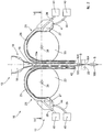
- unit 10 for filling packages 100 for a packaging machine, hereafter referred to as unit 10, which can be seen as a whole in fig. 1 .
- the sealed packages 100 are able to contain substances S, for example substances in powder, granules, tablets, typically of a food, pharmaceutical or cosmetic nature ( fig. 2 or 3 ).
- the unit 10 comprises a filling assembly 12 and a feeding assembly 13.
- the filling assembly 12 is able to remove the sheet material 101 with which the package 100 will be formed ( fig. 4 ), supports it and arranges it according to the shape that the package 100 will need to have. At the end of the filling, the package 100 can be sealed, in particular hermetically.
- the feeding assembly 13 is able to remove the substances S in order to insert them into the package 100.
- the filling assembly 12 and the feeding assembly 13 are able to cooperate with each other in order to feed the substance S into the package 100 while this is being formed and before it is sealed.
- the feed of this substance can occur continuously or discontinuously, interrupting, on each occasion, the pouring of the substance S into the package 100 when a predefined quantity has been reached.
- the feeding assembly 13 can comprise one or more conduits 16 for transporting the substance S.
- These one or more transport conduits 16 are able to allow the outflow of the substance S and to insert it inside the package 100.
- the one or more transport conduits 16 can for example be configured as hollow conduits inside which there are provided means 18 for moving the substance.
- these movement means 18 can be able to transport the substance S toward the package 100, and can be of various types known in the state of the art.
- the movement means 18 can be configured as volumetric pumps, augers, gears, worm screws, funnel elements and suchlike.
- the transport conduits 16 can end in the form of a nozzle 19 ( fig. 2 ), able to insert the substance S into the package 100 being formed without the substance S being poured outside.
- the nozzle 19 can be shaped as a funnel ending with a small tube 19a, for example a capillary, or according to similar configurations.
- the filling assembly 12 can comprise one or more support members 21 on which the sheet material 101 intended to form the package 100 flows ( fig. 1-3 ).
- the sheet material 101 can be a heat-sealable material.
- it can be a polymeric sheet material, such as a polymer/paper or paper/aluminum composite foil material, a metallic material such as aluminum foil or suchlike, or a combination thereof.
- it can be a transparent, or non-transparent, plastic film.
- the support members 21 can be shaped in order to confer on the sheet material 101 a desired arched shape intended to define one of the lateral walls 103 of the package 100.
- the support members 21 can define an internal volume 43 for the passage of the substance S to be inserted into the package 100.
- the filling assembly 12 comprises at least one pair of support members 21 for each transport conduit 16, each support member 21 being intended to support a respective sheet of sheet material 101 ( fig. 1 ).
- each support member 21 being intended to support a respective sheet of sheet material 101 ( fig. 1 ).
- a number of support members 21 greater than two can also be provided.
- each support member 21 has, at least in its upper part, an arched shape.
- each support member 21 can comprise an internal concave surface 28, intended to be exposed to a respective sheet material 101, and a convex external surface 29.
- This internal surface 28 is defined as the surface of an internal wall 32 of the support member 21.
- the external surface 29 is defined as the surface of an external wall 39 disposed on the opposite side with respect to a respective feed conduit 16, at the end of which the package 100 is being formed and filled.
- the support member 21 can be a hollow element, inside which the substance S can pass and on the outside of which the sheet material 101 can pass, pre-formed as a thin and flexible tube or casing.
- the concave shape of the internal surfaces 28 can limit and shield the internal volume 43 for the passage of the substance S, this volume 43 being delimited by the sheet material 101, in particular by the pair of sheet materials 101 intended to cooperate in order to form the package 100.
- the one or more support members 21 can have one or more cooling channels 25 for the passage of a cooling fluid.
- cooling fluid is able to protect the substances S from excessive heat.
- Such cooling fluids can be liquid or gaseous, for example they can be water or refrigerant liquids/gasses.
- the cooling fluid is advantageously at a lower temperature than that of the support members 21, which reach even high temperatures due to some elements of the unit 10, such as the elements that perform the heat-sealing, the drive motors and others still.
- the cooling fluid can be a fluid at room temperature or at a temperature below room temperature.
- the cooling channels 25 are integrated in the support members 21, at least in the proximity of their internal surface 28, so that the cooling fluid can lap at least one internal part 32 of the support members 21.
- the filling assembly 12 can comprise special attachments 31 for the connection to pipes 26 for the cooling fluids to enter and exit the support members 21 ( fig. 1 ).
- the pipes 26 can be in fluidic connection with actuator means 40 suitable to generate a flow of the cooling fluid in order to make it circulate in the one or more cooling channels 25.
- the actuator means 40 can comprise a compressor, a pump, movement conduits and suchlike.
- the cooling channels 25 are in hydraulic connection with each other, and the filling assembly 12 is provided with two attachments 31, respectively for the cooling fluid to enter and exit ( fig. 1 ).
- the filling assembly 12 is provided with two attachments 31, respectively for the cooling fluid to enter and exit ( fig. 1 ).
- the one or more support members 21 also have at least one internal cavity 27 defining means for the passage of a drying fluid configured to lap at least one external wall 39 of the support members 21.
- a drying fluid can be liquid or gaseous, for example it can be water or air.
- This at least one internal cavity 27 can be able to reduce or prevent the formation of condensation on components of the unit in contact with the sheets of material intended to form the package.
- condensation usually forms first on the external surface 29 of the support members 21 and subsequently also on their internal surface 28.
- This condensation can form due to the thermal gradient between the components in contact with the package 100 being formed and/or with the substances S to be inserted therein, kept cold so as not to alter the properties of the substances, and the hot parts, such as the heat-sealing rollers or the motors, and/or the environment heated by the latter.
- Drops of water of said condensation can fall, for example by gravity, inside the package 100 which is being filled, causing alterations of the substance contained in the package and/or the formation of molds, microorganisms, which can cause possible reductions in the efficacy of the substance itself and/or danger to human and animal health, and/or damage to the environment in which they are to be used.
- the internal cavities 27 can in fact be able to supply an insulated wall, isolating the cooling channels 25 from the external surface 29, allowing to reduce or eliminate the formation of condensation.
- the drying fluid favorably at room temperature or heated, can keep the external surface 29 at a higher temperature than that of the cooling fluid, once again allowing to reduce or prevent such formation of condensation.
- the at least one internal cavity 27 can be positioned adjacent to the external wall 39 of the support member 21, as shown in figs. from 2 to 4a.
- the cooling channels 25 can therefore be positioned between the internal cavities 27 and the internal wall 32, as shown in fig. 4a .
- the at least one internal cavity 27 is configured as a conduit provided with an inlet hole 41 and an outlet hole 42, through which the drying fluid respectively enters and exits the conduit.
- the inlet hole 41 can be in fluidic connection with actuator means 40 suitable to generate a flow of the drying fluid in order to make it circulate in the at least one internal cavity 27.
- actuator means 40 can comprise a compressor, a pump, hydraulic or pneumatic members or other similar actuators.
- the inlet hole 41 can have coupling means for coupling conduits 35 for the introduction and extraction of the drying fluid.
- the internal cavities 27 of the different support members 21 may or may not be hydraulically communicating with each other.
- the filling assembly 12 can be configured to cooperate with one or more attachment elements 22 able to attach the flaps 102 of the material to each other in order to close the package 100, in a known manner, by means of heat-sealing ( fig. 4 ).
- the attachment elements 22 can be comprised in the filling unit 10 or in an attachment unit outside the filling unit 10 and able to cooperate with the filling unit 10.
- the attachment elements 22 are able to attach the material on two or more edges 104, 105 of the package 100, for example on four edges.
- the attachment elements 22 can be able, for example, to attach the lateral edges 105, then the lower edge 104, and finally seal the package 100 by attaching the upper edge. As a further example, if the material is fed in tubular form, the attachment elements 22 can be able to attach only the lower edge 104 and the upper edge.
- the attachment elements 22 can comprise heating elements of a type known in the state of the art, for example electric resistances, for carrying out the heat-sealing.
- the attachment elements 22 can comprise some compression elements, such as for example rollers or foils or suchlike, heated by the heating elements, able to compress the flaps 102 of the material in order to attach them to each other.
- some compression elements such as for example rollers or foils or suchlike, heated by the heating elements, able to compress the flaps 102 of the material in order to attach them to each other.
- the cooling fluid allows to keep the temperature low in correspondence with the internal surface 28 of the support members 21, and therefore of the sheet material 101 and of the substance S.
- the temperature in correspondence with this zone would otherwise rise due to the proximity with the heated attachment elements 22.
- the filling assembly 12 can also cooperate with one or more elements 23 for moving the material.
- the movement elements 23 can be comprised in the filling unit 10 or in an attachment unit outside the filling unit 10 and able to cooperate with the filling unit 10.
- the movement elements 23 are drawing rollers.
- the movement elements 23 can coincide with the attachment elements 22, suitable to perform both an attachment action by means of heat-sealing and also a drawing action.
- the attachment elements 22 of the lateral edges can be high temperature drawing rollers which move the material downward (relative to the representation of figs. 2 and 3 ) and at the same time heat-seal the flaps 102 of the material to each other in order to form the lateral edges.
- the movement elements 23 can be rollers, moved by one or more motors.
- such movement elements 23 are constrained on a support element 33 able to hold the unit 10 in position ( fig. 1 ).
- These movement elements 23 rotate around a transmission shaft 38, which transmits the motion from the motor to the corresponding movement element 23.
- the movement elements 23 can transmit the movement to the sheet material intended to form the package by means of one or more cantilevered elements 34, positioned interposed between the support members 21 ( fig. 1 ).
- Some embodiments described here also concern a method for filling a package 100 by means of the filling unit 10 according to the invention.
- the method can provide to remove the sheet material 101 with which to form the package 100, to form at least a first edge of the package 100, to insert the substance S inside the package 100 and to seal the package 100 forming at least a second edge.
- the first edge of the package can be a lower edge 104.
- a small bag is formed, closed on three sides, into which the substance S can be inserted, in which there is defined a mouth in correspondence with the second upper edge, that is, opposite the first edge 104.
- the method can also provide to form one or more lateral edges 105, for example in the event the sheet material 101 is in the form of strips or sheets, and the forming of the package 100 occurs by coupling two or more strips or sheets.
- the method can provide to form two or more lateral edges 105 and one lower edge 104 of the package 100, for each package 100 that is being filled.
- the method can provide to insert the substance inside the package 100 when the lateral edges 105 and one lower edge 104 are formed, so as not to cause the substance to pour out of the package 100.
- the method can provide, at the end of the insertion of the predefined quantity of the substance S, to seal the package 100 forming at least one upper edge.
- the method provides that, during the filling of the package 100, a cooling fluid is fed into one or more cooling channels 25 integrated in support members 21, on which the sheet material 101 intended to form the package 100 flows, so as to lap at least one internal wall 32 intended to be exposed, in an internal surface 28 thereof, to the sheet material 101.
- a cooling fluid is fed into one or more cooling channels 25 integrated in support members 21, on which the sheet material 101 intended to form the package 100 flows, so as to lap at least one internal wall 32 intended to be exposed, in an internal surface 28 thereof, to the sheet material 101.
- the method prevents undesired temperature rises which can affect the sheet material 101 and/or the substance S.
- this cooling fluid is at room temperature and/or in any case at a lower temperature than that of the support members 21, the temperature of which can rise due to elements of the unit 10, such as heat-sealing elements, motors and suchlike.
- the cooling fluid can be at or below room temperature.
- the method further provides to make a drying fluid circulate in at least one internal cavity 27 comprised in the members 21 for supporting the sheet material 101.
- the method provides that the drying fluid laps at least one external wall 39 of the support members 21, the external wall 39 facing toward the opposite side with respect to the internal surface 28.
- a packaging machine comprising a unit 10 for filling packages 100 as described above, able to carry out the method for filling a package 100 according to the present invention.
Landscapes
- Engineering & Computer Science (AREA)
- Mechanical Engineering (AREA)
- Containers And Plastic Fillers For Packaging (AREA)
- Auxiliary Devices For And Details Of Packaging Control (AREA)
Applications Claiming Priority (2)
| Application Number | Priority Date | Filing Date | Title |
|---|---|---|---|
| IT102020000001891A IT202000001891A1 (it) | 2020-01-31 | 2020-01-31 | Gruppo di riempimento involucri e relativo procedimento |
| IT102020000001885A IT202000001885A1 (it) | 2020-01-31 | 2020-01-31 | Gruppo di riempimento involucri e relativo procedimento |
Publications (2)
| Publication Number | Publication Date |
|---|---|
| EP3858743A1 true EP3858743A1 (de) | 2021-08-04 |
| EP3858743B1 EP3858743B1 (de) | 2023-11-01 |
Family
ID=74187222
Family Applications (1)
| Application Number | Title | Priority Date | Filing Date |
|---|---|---|---|
| EP21153598.4A Active EP3858743B1 (de) | 2020-01-31 | 2021-01-26 | Einheit zum befüllen von verpackungen und entsprechendes verfahren |
Country Status (2)
| Country | Link |
|---|---|
| EP (1) | EP3858743B1 (de) |
| ES (1) | ES2969769T3 (de) |
Citations (5)
| Publication number | Priority date | Publication date | Assignee | Title |
|---|---|---|---|---|
| US2759308A (en) | 1953-10-05 | 1956-08-21 | Clearfield Cheese Company | Apparatus for producing individually wrapped cheese slabs |
| GB1137649A (en) | 1966-08-09 | 1968-12-27 | Exxon Research Engineering Co | Improvements in packaging |
| US3930350A (en) | 1974-11-29 | 1976-01-06 | W. R. Grace & Co. | Packaging assembly and process |
| EP0119957A1 (de) | 1983-03-14 | 1984-09-26 | SIG Schweizerische Industrie-Gesellschaft | Formvorrichtung zur Bildung eines Einflossenschlauches |
| US6058680A (en) | 1989-06-05 | 2000-05-09 | Schreiber Foods, Inc. | Method and apparatus for forming and hermetically sealing slices of food items |
-
2021
- 2021-01-26 EP EP21153598.4A patent/EP3858743B1/de active Active
- 2021-01-26 ES ES21153598T patent/ES2969769T3/es active Active
Patent Citations (5)
| Publication number | Priority date | Publication date | Assignee | Title |
|---|---|---|---|---|
| US2759308A (en) | 1953-10-05 | 1956-08-21 | Clearfield Cheese Company | Apparatus for producing individually wrapped cheese slabs |
| GB1137649A (en) | 1966-08-09 | 1968-12-27 | Exxon Research Engineering Co | Improvements in packaging |
| US3930350A (en) | 1974-11-29 | 1976-01-06 | W. R. Grace & Co. | Packaging assembly and process |
| EP0119957A1 (de) | 1983-03-14 | 1984-09-26 | SIG Schweizerische Industrie-Gesellschaft | Formvorrichtung zur Bildung eines Einflossenschlauches |
| US6058680A (en) | 1989-06-05 | 2000-05-09 | Schreiber Foods, Inc. | Method and apparatus for forming and hermetically sealing slices of food items |
Also Published As
| Publication number | Publication date |
|---|---|
| EP3858743B1 (de) | 2023-11-01 |
| ES2969769T3 (es) | 2024-05-22 |
Similar Documents
| Publication | Publication Date | Title |
|---|---|---|
| US8544245B2 (en) | Packaging machine for multilayer lid foil | |
| US5806285A (en) | Process and packaging plant for packaging sticky substances in the fluid state | |
| US9428289B2 (en) | Method and apparatus for making medium-filled packages | |
| US3911640A (en) | Method for the packing under aseptic conditions of sterile goods into containers | |
| AU749585B2 (en) | Device for packaging materials in a vacuum chamber | |
| CN102791581B (zh) | 包装机及包装产品的方法 | |
| HRP20050054A2 (en) | Packaging method and device | |
| KR20040016997A (ko) | 제조용 장치, 방법 및 가요성 백 | |
| SE535972C2 (sv) | Anordning och förfarande att packa varor i ett uppblåsbart påsämne | |
| CS173291A3 (en) | Forming device for packaging machines | |
| JP7224378B2 (ja) | 包装材料のシート上に開放機器を射出成形するように構成された成形装置 | |
| BR112018005912B1 (pt) | Dispositivo para esvaziar o gás de uma embalagem em um aparelho de embalar, processo de embalar para uso com o dispositivo, e aparelho de embalar | |
| EP3858743B1 (de) | Einheit zum befüllen von verpackungen und entsprechendes verfahren | |
| JP2009012858A (ja) | 加工食品の複数列式真空連続包装装置 | |
| JP6097613B2 (ja) | 帯状フィルムを用いた製袋充填方法および製袋充填装置 | |
| CN104024110A (zh) | 改进的泡罩制造机、包装到泡罩中的连接方法及因此获得的泡罩包装 | |
| EP0832819A1 (de) | Vakuumverpackungsvorrichtung, insbesondere für Nahrungsmittel | |
| ITBO20130266A1 (it) | Sacca contenente bicarbonato in polvere | |
| ITBO970751A1 (it) | Confezione ermetica per prodotti di consistenza pastosa in particolare prodotti derivati dal latte, quali porzioni di formaggio fuso e metodo | |
| IT202000001885A1 (it) | Gruppo di riempimento involucri e relativo procedimento | |
| IT202000001891A1 (it) | Gruppo di riempimento involucri e relativo procedimento | |
| JPH08113211A (ja) | 不活性ガス封入包装機 | |
| ES2750206T3 (es) | Procedimiento de envasado de sustancias pegajosas en la fase fluida con una película fina | |
| JP6122678B2 (ja) | 帯状フィルムを用いた製袋充填方法および製袋充填装置 | |
| CN110225866B (zh) | 用于生产用于制备食品或饮料产品的包袋的方法和设备 |
Legal Events
| Date | Code | Title | Description |
|---|---|---|---|
| PUAI | Public reference made under article 153(3) epc to a published international application that has entered the european phase |
Free format text: ORIGINAL CODE: 0009012 |
|
| STAA | Information on the status of an ep patent application or granted ep patent |
Free format text: STATUS: THE APPLICATION HAS BEEN PUBLISHED |
|
| AK | Designated contracting states |
Kind code of ref document: A1 Designated state(s): AL AT BE BG CH CY CZ DE DK EE ES FI FR GB GR HR HU IE IS IT LI LT LU LV MC MK MT NL NO PL PT RO RS SE SI SK SM TR |
|
| STAA | Information on the status of an ep patent application or granted ep patent |
Free format text: STATUS: REQUEST FOR EXAMINATION WAS MADE |
|
| 17P | Request for examination filed |
Effective date: 20220201 |
|
| RBV | Designated contracting states (corrected) |
Designated state(s): AL AT BE BG CH CY CZ DE DK EE ES FI FR GB GR HR HU IE IS IT LI LT LU LV MC MK MT NL NO PL PT RO RS SE SI SK SM TR |
|
| GRAP | Despatch of communication of intention to grant a patent |
Free format text: ORIGINAL CODE: EPIDOSNIGR1 |
|
| STAA | Information on the status of an ep patent application or granted ep patent |
Free format text: STATUS: GRANT OF PATENT IS INTENDED |
|
| INTG | Intention to grant announced |
Effective date: 20230515 |
|
| P01 | Opt-out of the competence of the unified patent court (upc) registered |
Effective date: 20230520 |
|
| GRAS | Grant fee paid |
Free format text: ORIGINAL CODE: EPIDOSNIGR3 |
|
| GRAA | (expected) grant |
Free format text: ORIGINAL CODE: 0009210 |
|
| STAA | Information on the status of an ep patent application or granted ep patent |
Free format text: STATUS: THE PATENT HAS BEEN GRANTED |
|
| AK | Designated contracting states |
Kind code of ref document: B1 Designated state(s): AL AT BE BG CH CY CZ DE DK EE ES FI FR GB GR HR HU IE IS IT LI LT LU LV MC MK MT NL NO PL PT RO RS SE SI SK SM TR |
|
| REG | Reference to a national code |
Ref country code: GB Ref legal event code: FG4D |
|
| REG | Reference to a national code |
Ref country code: CH Ref legal event code: EP |
|
| REG | Reference to a national code |
Ref country code: DE Ref legal event code: R096 Ref document number: 602021006281 Country of ref document: DE |
|
| REG | Reference to a national code |
Ref country code: IE Ref legal event code: FG4D |
|
| REG | Reference to a national code |
Ref country code: LT Ref legal event code: MG9D |
|
| REG | Reference to a national code |
Ref country code: NL Ref legal event code: MP Effective date: 20231101 |
|
| PG25 | Lapsed in a contracting state [announced via postgrant information from national office to epo] |
Ref country code: GR Free format text: LAPSE BECAUSE OF FAILURE TO SUBMIT A TRANSLATION OF THE DESCRIPTION OR TO PAY THE FEE WITHIN THE PRESCRIBED TIME-LIMIT Effective date: 20240202 |
|
| PG25 | Lapsed in a contracting state [announced via postgrant information from national office to epo] |
Ref country code: IS Free format text: LAPSE BECAUSE OF FAILURE TO SUBMIT A TRANSLATION OF THE DESCRIPTION OR TO PAY THE FEE WITHIN THE PRESCRIBED TIME-LIMIT Effective date: 20240301 |
|
| PG25 | Lapsed in a contracting state [announced via postgrant information from national office to epo] |
Ref country code: LT Free format text: LAPSE BECAUSE OF FAILURE TO SUBMIT A TRANSLATION OF THE DESCRIPTION OR TO PAY THE FEE WITHIN THE PRESCRIBED TIME-LIMIT Effective date: 20231101 |
|
| REG | Reference to a national code |
Ref country code: AT Ref legal event code: MK05 Ref document number: 1626970 Country of ref document: AT Kind code of ref document: T Effective date: 20231101 |
|
| PG25 | Lapsed in a contracting state [announced via postgrant information from national office to epo] |
Ref country code: NL Free format text: LAPSE BECAUSE OF FAILURE TO SUBMIT A TRANSLATION OF THE DESCRIPTION OR TO PAY THE FEE WITHIN THE PRESCRIBED TIME-LIMIT Effective date: 20231101 |
|
| PG25 | Lapsed in a contracting state [announced via postgrant information from national office to epo] |
Ref country code: AT Free format text: LAPSE BECAUSE OF FAILURE TO SUBMIT A TRANSLATION OF THE DESCRIPTION OR TO PAY THE FEE WITHIN THE PRESCRIBED TIME-LIMIT Effective date: 20231101 |
|
| PG25 | Lapsed in a contracting state [announced via postgrant information from national office to epo] |
Ref country code: NL Free format text: LAPSE BECAUSE OF FAILURE TO SUBMIT A TRANSLATION OF THE DESCRIPTION OR TO PAY THE FEE WITHIN THE PRESCRIBED TIME-LIMIT Effective date: 20231101 Ref country code: LT Free format text: LAPSE BECAUSE OF FAILURE TO SUBMIT A TRANSLATION OF THE DESCRIPTION OR TO PAY THE FEE WITHIN THE PRESCRIBED TIME-LIMIT Effective date: 20231101 Ref country code: IS Free format text: LAPSE BECAUSE OF FAILURE TO SUBMIT A TRANSLATION OF THE DESCRIPTION OR TO PAY THE FEE WITHIN THE PRESCRIBED TIME-LIMIT Effective date: 20240301 Ref country code: GR Free format text: LAPSE BECAUSE OF FAILURE TO SUBMIT A TRANSLATION OF THE DESCRIPTION OR TO PAY THE FEE WITHIN THE PRESCRIBED TIME-LIMIT Effective date: 20240202 Ref country code: BG Free format text: LAPSE BECAUSE OF FAILURE TO SUBMIT A TRANSLATION OF THE DESCRIPTION OR TO PAY THE FEE WITHIN THE PRESCRIBED TIME-LIMIT Effective date: 20240201 Ref country code: AT Free format text: LAPSE BECAUSE OF FAILURE TO SUBMIT A TRANSLATION OF THE DESCRIPTION OR TO PAY THE FEE WITHIN THE PRESCRIBED TIME-LIMIT Effective date: 20231101 Ref country code: PT Free format text: LAPSE BECAUSE OF FAILURE TO SUBMIT A TRANSLATION OF THE DESCRIPTION OR TO PAY THE FEE WITHIN THE PRESCRIBED TIME-LIMIT Effective date: 20240301 |
|
| REG | Reference to a national code |
Ref country code: ES Ref legal event code: FG2A Ref document number: 2969769 Country of ref document: ES Kind code of ref document: T3 Effective date: 20240522 |
|
| PG25 | Lapsed in a contracting state [announced via postgrant information from national office to epo] |
Ref country code: SE Free format text: LAPSE BECAUSE OF FAILURE TO SUBMIT A TRANSLATION OF THE DESCRIPTION OR TO PAY THE FEE WITHIN THE PRESCRIBED TIME-LIMIT Effective date: 20231101 Ref country code: RS Free format text: LAPSE BECAUSE OF FAILURE TO SUBMIT A TRANSLATION OF THE DESCRIPTION OR TO PAY THE FEE WITHIN THE PRESCRIBED TIME-LIMIT Effective date: 20231101 Ref country code: PL Free format text: LAPSE BECAUSE OF FAILURE TO SUBMIT A TRANSLATION OF THE DESCRIPTION OR TO PAY THE FEE WITHIN THE PRESCRIBED TIME-LIMIT Effective date: 20231101 Ref country code: NO Free format text: LAPSE BECAUSE OF FAILURE TO SUBMIT A TRANSLATION OF THE DESCRIPTION OR TO PAY THE FEE WITHIN THE PRESCRIBED TIME-LIMIT Effective date: 20240201 Ref country code: LV Free format text: LAPSE BECAUSE OF FAILURE TO SUBMIT A TRANSLATION OF THE DESCRIPTION OR TO PAY THE FEE WITHIN THE PRESCRIBED TIME-LIMIT Effective date: 20231101 Ref country code: HR Free format text: LAPSE BECAUSE OF FAILURE TO SUBMIT A TRANSLATION OF THE DESCRIPTION OR TO PAY THE FEE WITHIN THE PRESCRIBED TIME-LIMIT Effective date: 20231101 |
|
| PG25 | Lapsed in a contracting state [announced via postgrant information from national office to epo] |
Ref country code: DK Free format text: LAPSE BECAUSE OF FAILURE TO SUBMIT A TRANSLATION OF THE DESCRIPTION OR TO PAY THE FEE WITHIN THE PRESCRIBED TIME-LIMIT Effective date: 20231101 |
|
| PG25 | Lapsed in a contracting state [announced via postgrant information from national office to epo] |
Ref country code: CZ Free format text: LAPSE BECAUSE OF FAILURE TO SUBMIT A TRANSLATION OF THE DESCRIPTION OR TO PAY THE FEE WITHIN THE PRESCRIBED TIME-LIMIT Effective date: 20231101 |
|
| PG25 | Lapsed in a contracting state [announced via postgrant information from national office to epo] |
Ref country code: SK Free format text: LAPSE BECAUSE OF FAILURE TO SUBMIT A TRANSLATION OF THE DESCRIPTION OR TO PAY THE FEE WITHIN THE PRESCRIBED TIME-LIMIT Effective date: 20231101 |
|
| PG25 | Lapsed in a contracting state [announced via postgrant information from national office to epo] |
Ref country code: SM Free format text: LAPSE BECAUSE OF FAILURE TO SUBMIT A TRANSLATION OF THE DESCRIPTION OR TO PAY THE FEE WITHIN THE PRESCRIBED TIME-LIMIT Effective date: 20231101 Ref country code: SK Free format text: LAPSE BECAUSE OF FAILURE TO SUBMIT A TRANSLATION OF THE DESCRIPTION OR TO PAY THE FEE WITHIN THE PRESCRIBED TIME-LIMIT Effective date: 20231101 Ref country code: EE Free format text: LAPSE BECAUSE OF FAILURE TO SUBMIT A TRANSLATION OF THE DESCRIPTION OR TO PAY THE FEE WITHIN THE PRESCRIBED TIME-LIMIT Effective date: 20231101 Ref country code: DK Free format text: LAPSE BECAUSE OF FAILURE TO SUBMIT A TRANSLATION OF THE DESCRIPTION OR TO PAY THE FEE WITHIN THE PRESCRIBED TIME-LIMIT Effective date: 20231101 Ref country code: CZ Free format text: LAPSE BECAUSE OF FAILURE TO SUBMIT A TRANSLATION OF THE DESCRIPTION OR TO PAY THE FEE WITHIN THE PRESCRIBED TIME-LIMIT Effective date: 20231101 |
|
| REG | Reference to a national code |
Ref country code: DE Ref legal event code: R097 Ref document number: 602021006281 Country of ref document: DE |
|
| PG25 | Lapsed in a contracting state [announced via postgrant information from national office to epo] |
Ref country code: MC Free format text: LAPSE BECAUSE OF FAILURE TO SUBMIT A TRANSLATION OF THE DESCRIPTION OR TO PAY THE FEE WITHIN THE PRESCRIBED TIME-LIMIT Effective date: 20231101 |
|
| PG25 | Lapsed in a contracting state [announced via postgrant information from national office to epo] |
Ref country code: MC Free format text: LAPSE BECAUSE OF FAILURE TO SUBMIT A TRANSLATION OF THE DESCRIPTION OR TO PAY THE FEE WITHIN THE PRESCRIBED TIME-LIMIT Effective date: 20231101 |
|
| REG | Reference to a national code |
Ref country code: CH Ref legal event code: PL |
|
| PLBE | No opposition filed within time limit |
Free format text: ORIGINAL CODE: 0009261 |
|
| STAA | Information on the status of an ep patent application or granted ep patent |
Free format text: STATUS: NO OPPOSITION FILED WITHIN TIME LIMIT |
|
| PG25 | Lapsed in a contracting state [announced via postgrant information from national office to epo] |
Ref country code: LU Free format text: LAPSE BECAUSE OF NON-PAYMENT OF DUE FEES Effective date: 20240126 |
|
| PG25 | Lapsed in a contracting state [announced via postgrant information from national office to epo] |
Ref country code: LU Free format text: LAPSE BECAUSE OF NON-PAYMENT OF DUE FEES Effective date: 20240126 |
|
| 26N | No opposition filed |
Effective date: 20240802 |
|
| PG25 | Lapsed in a contracting state [announced via postgrant information from national office to epo] |
Ref country code: BE Free format text: LAPSE BECAUSE OF NON-PAYMENT OF DUE FEES Effective date: 20240131 |
|
| PG25 | Lapsed in a contracting state [announced via postgrant information from national office to epo] |
Ref country code: FR Free format text: LAPSE BECAUSE OF NON-PAYMENT OF DUE FEES Effective date: 20240131 |
|
| PG25 | Lapsed in a contracting state [announced via postgrant information from national office to epo] |
Ref country code: CH Free format text: LAPSE BECAUSE OF NON-PAYMENT OF DUE FEES Effective date: 20240131 |
|
| PG25 | Lapsed in a contracting state [announced via postgrant information from national office to epo] |
Ref country code: SI Free format text: LAPSE BECAUSE OF FAILURE TO SUBMIT A TRANSLATION OF THE DESCRIPTION OR TO PAY THE FEE WITHIN THE PRESCRIBED TIME-LIMIT Effective date: 20231101 |
|
| PG25 | Lapsed in a contracting state [announced via postgrant information from national office to epo] |
Ref country code: SI Free format text: LAPSE BECAUSE OF FAILURE TO SUBMIT A TRANSLATION OF THE DESCRIPTION OR TO PAY THE FEE WITHIN THE PRESCRIBED TIME-LIMIT Effective date: 20231101 Ref country code: FR Free format text: LAPSE BECAUSE OF NON-PAYMENT OF DUE FEES Effective date: 20240131 Ref country code: CH Free format text: LAPSE BECAUSE OF NON-PAYMENT OF DUE FEES Effective date: 20240131 Ref country code: BE Free format text: LAPSE BECAUSE OF NON-PAYMENT OF DUE FEES Effective date: 20240131 |
|
| REG | Reference to a national code |
Ref country code: BE Ref legal event code: MM Effective date: 20240131 |
|
| PG25 | Lapsed in a contracting state [announced via postgrant information from national office to epo] |
Ref country code: IE Free format text: LAPSE BECAUSE OF NON-PAYMENT OF DUE FEES Effective date: 20240126 |
|
| PG25 | Lapsed in a contracting state [announced via postgrant information from national office to epo] |
Ref country code: IE Free format text: LAPSE BECAUSE OF NON-PAYMENT OF DUE FEES Effective date: 20240126 |
|
| PG25 | Lapsed in a contracting state [announced via postgrant information from national office to epo] |
Ref country code: RO Free format text: LAPSE BECAUSE OF FAILURE TO SUBMIT A TRANSLATION OF THE DESCRIPTION OR TO PAY THE FEE WITHIN THE PRESCRIBED TIME-LIMIT Effective date: 20231101 |
|
| PG25 | Lapsed in a contracting state [announced via postgrant information from national office to epo] |
Ref country code: CY Free format text: LAPSE BECAUSE OF FAILURE TO SUBMIT A TRANSLATION OF THE DESCRIPTION OR TO PAY THE FEE WITHIN THE PRESCRIBED TIME-LIMIT; INVALID AB INITIO Effective date: 20210126 |
|
| PG25 | Lapsed in a contracting state [announced via postgrant information from national office to epo] |
Ref country code: HU Free format text: LAPSE BECAUSE OF FAILURE TO SUBMIT A TRANSLATION OF THE DESCRIPTION OR TO PAY THE FEE WITHIN THE PRESCRIBED TIME-LIMIT; INVALID AB INITIO Effective date: 20210126 |
|
| GBPC | Gb: european patent ceased through non-payment of renewal fee |
Effective date: 20250126 |
|
| PG25 | Lapsed in a contracting state [announced via postgrant information from national office to epo] |
Ref country code: FI Free format text: LAPSE BECAUSE OF FAILURE TO SUBMIT A TRANSLATION OF THE DESCRIPTION OR TO PAY THE FEE WITHIN THE PRESCRIBED TIME-LIMIT Effective date: 20231101 |
|
| PG25 | Lapsed in a contracting state [announced via postgrant information from national office to epo] |
Ref country code: GB Free format text: LAPSE BECAUSE OF NON-PAYMENT OF DUE FEES Effective date: 20250126 |
|
| PG25 | Lapsed in a contracting state [announced via postgrant information from national office to epo] |
Ref country code: TR Free format text: LAPSE BECAUSE OF FAILURE TO SUBMIT A TRANSLATION OF THE DESCRIPTION OR TO PAY THE FEE WITHIN THE PRESCRIBED TIME-LIMIT Effective date: 20231101 |
|
| PGFP | Annual fee paid to national office [announced via postgrant information from national office to epo] |
Ref country code: ES Payment date: 20260210 Year of fee payment: 6 |
|
| PGFP | Annual fee paid to national office [announced via postgrant information from national office to epo] |
Ref country code: DE Payment date: 20260127 Year of fee payment: 6 |
|
| PGFP | Annual fee paid to national office [announced via postgrant information from national office to epo] |
Ref country code: IT Payment date: 20251209 Year of fee payment: 6 |