EP3859480A1 - Procédé de commande de véhicule aérien sans pilote, dispositif et système de pulvérisation et véhicule aérien sans pilote et support d'informations - Google Patents
Procédé de commande de véhicule aérien sans pilote, dispositif et système de pulvérisation et véhicule aérien sans pilote et support d'informations Download PDFInfo
- Publication number
- EP3859480A1 EP3859480A1 EP19926779.0A EP19926779A EP3859480A1 EP 3859480 A1 EP3859480 A1 EP 3859480A1 EP 19926779 A EP19926779 A EP 19926779A EP 3859480 A1 EP3859480 A1 EP 3859480A1
- Authority
- EP
- European Patent Office
- Prior art keywords
- nozzle
- unmanned aerial
- aerial vehicle
- area
- crops
- Prior art date
- Legal status (The legal status is an assumption and is not a legal conclusion. Google has not performed a legal analysis and makes no representation as to the accuracy of the status listed.)
- Withdrawn
Links
Images
Classifications
-
- A—HUMAN NECESSITIES
- A01—AGRICULTURE; FORESTRY; ANIMAL HUSBANDRY; HUNTING; TRAPPING; FISHING
- A01M—CATCHING, TRAPPING OR SCARING OF ANIMALS; APPARATUS FOR THE DESTRUCTION OF NOXIOUS ANIMALS OR NOXIOUS PLANTS
- A01M7/00—Special adaptations or arrangements of liquid-spraying apparatus for purposes covered by this subclass
- A01M7/0089—Regulating or controlling systems
-
- A—HUMAN NECESSITIES
- A01—AGRICULTURE; FORESTRY; ANIMAL HUSBANDRY; HUNTING; TRAPPING; FISHING
- A01B—SOIL WORKING IN AGRICULTURE OR FORESTRY; PARTS, DETAILS, OR ACCESSORIES OF AGRICULTURAL MACHINES OR IMPLEMENTS, IN GENERAL
- A01B79/00—Methods for working soil
- A01B79/005—Precision agriculture
-
- A—HUMAN NECESSITIES
- A01—AGRICULTURE; FORESTRY; ANIMAL HUSBANDRY; HUNTING; TRAPPING; FISHING
- A01M—CATCHING, TRAPPING OR SCARING OF ANIMALS; APPARATUS FOR THE DESTRUCTION OF NOXIOUS ANIMALS OR NOXIOUS PLANTS
- A01M7/00—Special adaptations or arrangements of liquid-spraying apparatus for purposes covered by this subclass
- A01M7/005—Special arrangements or adaptations of the spraying or distributing parts, e.g. adaptations or mounting of the spray booms, mounting of the nozzles, protection shields
- A01M7/006—Mounting of the nozzles
-
- B—PERFORMING OPERATIONS; TRANSPORTING
- B05—SPRAYING OR ATOMISING IN GENERAL; APPLYING FLUENT MATERIALS TO SURFACES, IN GENERAL
- B05B—SPRAYING APPARATUS; ATOMISING APPARATUS; NOZZLES
- B05B12/00—Arrangements for controlling delivery; Arrangements for controlling the spray area
- B05B12/02—Arrangements for controlling delivery; Arrangements for controlling the spray area for controlling time, or sequence, of delivery
- B05B12/04—Arrangements for controlling delivery; Arrangements for controlling the spray area for controlling time, or sequence, of delivery for sequential operation or multiple outlets
-
- B—PERFORMING OPERATIONS; TRANSPORTING
- B05—SPRAYING OR ATOMISING IN GENERAL; APPLYING FLUENT MATERIALS TO SURFACES, IN GENERAL
- B05B—SPRAYING APPARATUS; ATOMISING APPARATUS; NOZZLES
- B05B12/00—Arrangements for controlling delivery; Arrangements for controlling the spray area
- B05B12/08—Arrangements for controlling delivery; Arrangements for controlling the spray area responsive to condition of liquid or other fluent material to be discharged, of ambient medium or of target ; responsive to condition of spray devices or of supply means, e.g. pipes, pumps or their drive means
- B05B12/12—Arrangements for controlling delivery; Arrangements for controlling the spray area responsive to condition of liquid or other fluent material to be discharged, of ambient medium or of target ; responsive to condition of spray devices or of supply means, e.g. pipes, pumps or their drive means responsive to conditions of ambient medium or target, e.g. humidity, temperature position or movement of the target relative to the spray apparatus
- B05B12/122—Arrangements for controlling delivery; Arrangements for controlling the spray area responsive to condition of liquid or other fluent material to be discharged, of ambient medium or of target ; responsive to condition of spray devices or of supply means, e.g. pipes, pumps or their drive means responsive to conditions of ambient medium or target, e.g. humidity, temperature position or movement of the target relative to the spray apparatus responsive to presence or shape of target
-
- B—PERFORMING OPERATIONS; TRANSPORTING
- B05—SPRAYING OR ATOMISING IN GENERAL; APPLYING FLUENT MATERIALS TO SURFACES, IN GENERAL
- B05B—SPRAYING APPARATUS; ATOMISING APPARATUS; NOZZLES
- B05B13/00—Machines or plants for applying liquids or other fluent materials to surfaces of objects or other work by spraying, not covered by groups B05B1/00 - B05B11/00
- B05B13/005—Machines or plants for applying liquids or other fluent materials to surfaces of objects or other work by spraying, not covered by groups B05B1/00 - B05B11/00 mounted on vehicles or designed to apply a liquid on a very large surface, e.g. on the road, on the surface of large containers
-
- G—PHYSICS
- G05—CONTROLLING; REGULATING
- G05D—SYSTEMS FOR CONTROLLING OR REGULATING NON-ELECTRIC VARIABLES
- G05D1/00—Control of position, course, altitude or attitude of land, water, air or space vehicles, e.g. using automatic pilots
- G05D1/0094—Control of position, course, altitude or attitude of land, water, air or space vehicles, e.g. using automatic pilots involving pointing a payload, e.g. camera, weapon, sensor, towards a fixed or moving target
-
- B—PERFORMING OPERATIONS; TRANSPORTING
- B64—AIRCRAFT; AVIATION; COSMONAUTICS
- B64D—EQUIPMENT FOR FITTING IN OR TO AIRCRAFT; FLIGHT SUITS; PARACHUTES; ARRANGEMENT OR MOUNTING OF POWER PLANTS OR PROPULSION TRANSMISSIONS IN AIRCRAFT
- B64D1/00—Dropping, ejecting, releasing or receiving articles, liquids, or the like, in flight
- B64D1/16—Dropping or releasing powdered, liquid, or gaseous matter, e.g. for fire-fighting
- B64D1/18—Dropping or releasing powdered, liquid, or gaseous matter, e.g. for fire-fighting by spraying, e.g. insecticides
-
- B—PERFORMING OPERATIONS; TRANSPORTING
- B64—AIRCRAFT; AVIATION; COSMONAUTICS
- B64U—UNMANNED AERIAL VEHICLES [UAV]; EQUIPMENT THEREFOR
- B64U2101/00—UAVs specially adapted for particular uses or applications
- B64U2101/30—UAVs specially adapted for particular uses or applications for imaging, photography or videography
-
- B—PERFORMING OPERATIONS; TRANSPORTING
- B64—AIRCRAFT; AVIATION; COSMONAUTICS
- B64U—UNMANNED AERIAL VEHICLES [UAV]; EQUIPMENT THEREFOR
- B64U2101/00—UAVs specially adapted for particular uses or applications
- B64U2101/40—UAVs specially adapted for particular uses or applications for agriculture or forestry operations
-
- B—PERFORMING OPERATIONS; TRANSPORTING
- B64—AIRCRAFT; AVIATION; COSMONAUTICS
- B64U—UNMANNED AERIAL VEHICLES [UAV]; EQUIPMENT THEREFOR
- B64U2101/00—UAVs specially adapted for particular uses or applications
- B64U2101/45—UAVs specially adapted for particular uses or applications for releasing liquids or powders in-flight, e.g. crop-dusting
-
- B—PERFORMING OPERATIONS; TRANSPORTING
- B64—AIRCRAFT; AVIATION; COSMONAUTICS
- B64U—UNMANNED AERIAL VEHICLES [UAV]; EQUIPMENT THEREFOR
- B64U2201/00—UAVs characterised by their flight controls
- B64U2201/20—Remote controls
Definitions
- Embodiments of the present invention relate to the field of unmanned aerial vehicles, and in particular, to a method and a device for controlling an unmanned aerial vehicle, a spraying system, an unmanned aerial vehicle, and a storage medium.
- an unmanned aerial vehicle for example, an agricultural unmanned aerial vehicle
- an agricultural unmanned aerial vehicle may be used for spraying operations.
- a plurality of nozzles and a tank for carrying pesticides are disposed on the agricultural unmanned aerial vehicle.
- the agricultural unmanned aerial vehicle turns on all nozzles and controls the plurality of nozzles to simultaneously spray pesticide down.
- Embodiments of the present invention provide a method and a device for controlling an unmanned aerial vehicle, a spraying system, an unmanned aerial vehicle, and a storage medium, to avoid great waste of pesticide when the unmanned aerial vehicle is performing a spraying task.
- a first aspect of embodiments of the present invention provides a method for controlling an unmanned aerial vehicle.
- a plurality of nozzles are disposed on the unmanned aerial vehicle, and the nozzles are configured to perform a spraying task on crops in a target area.
- the method comprises: obtaining location information and attitude information of the unmanned aerial vehicle; determining a spraying area of each nozzle in the target area based on the location information of the unmanned aerial vehicle and the attitude information of the unmanned aerial vehicle; determining whether there are crops in the spraying area corresponding to each nozzle; upon determining that there are crops in the spraying area of the nozzle, controlling the nozzle to be ON, otherwise, controlling the nozzle to be OFF.
- a second aspect of embodiments of the present invention provides a device for control an unmanned aerial vehicle.
- a plurality of nozzles are disposed on the unmanned aerial vehicle, and the nozzles are configured to perform a spraying task on crops in a target area.
- the control device comprises a memory and a processor, the memory is configured to store program code, and the processor is configured to invoke the program code and perform the following operations when the program code is executed: obtaining location information and attitude information of the unmanned aerial vehicle, determining a spraying area of each nozzle in the target area based on the location information of the unmanned aerial vehicle and the attitude information of the unmanned aerial vehicle, determining whether there are crops in the spraying area corresponding to each nozzle, upon determining that there are crops in the spraying area of the nozzle, controlling the nozzle to be ON, otherwise controlling the nozzle to be OFF.
- a third aspect of embodiments of the present invention provides a spraying system of an unmanned aerial vehicle.
- the unmanned aerial vehicle performs a spraying task on crops in a target area.
- the spraying system of the unmanned aerial vehicle comprises: a plurality of nozzles, mounted on a fuselage of the unmanned aerial vehicle; a nozzle control system, configured to control the plurality of nozzles to be ON or OFF, and the control device according to the second aspect.
- a fourth aspect of embodiments of the present invention provides an unmanned aerial vehicle.
- the unmanned aerial vehicle comprises: a fuselage; a power system, mounted in the fuselage and configured to supply power for flying; and the spraying system of the unmanned aerial vehicle according to the third aspect.
- a fifth aspect of embodiments of the present invention provides a computer-readable storage medium.
- the computer-readable storage medium stores a computer program, and the computer program is executed by a processor to implement the method according to the first aspect.
- the spraying system, the unmanned aerial vehicle, and the storage medium provided by the embodiments, by determining the spraying area of each nozzle in the target area based on the location information of the unmanned aerial vehicle and the attitude information of the unmanned aerial vehicle and further determining whether there are crops in the spraying area corresponding to each nozzle, which nozzle corresponds to a spraying area with crops and which nozzle corresponds to a spraying area without crops can be determined; and if there are crops in the spraying area of a nozzle, the nozzle is controlled to be ON, otherwise, the nozzle is controlled to be OFF. Therefore, waste of pesticide can be effectively avoided in comparison with an operation mode of turning on all nozzles of an unmanned aerial vehicle to spray simultaneously.
- ком ⁇ онент when a component is described as “fixed” to another component, the component may be directly located on another component, or an intermediate component may exist therebetween. When a component is considered as “connected” to another component, the component may be directly connected to another element, or an intermediate element may exist therebetween.
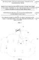
- FIG. 1 is a flowchart of a method for controlling an unmanned aerial vehicle according to an embodiment of the present invention.
- a plurality of nozzles are disposed on the unmanned aerial vehicle, and the nozzles are configured to perform a spraying task on crops in a target area.
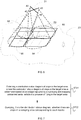
- a plurality of nozzles 22 are disposed on an unmanned aerial vehicle 21.
- the number of the nozzles is not limited, and a mounting position of each nozzle on the unmanned aerial vehicle 21 is not limited either.
- the unmanned aerial vehicle 21 is specifically an agricultural unmanned aerial vehicle.
- each group of nozzles includes two nozzles.
- the nozzles on the unmanned aerial vehicle 21 are configured to perform a spraying task on crops in a target area 23.
- types of crops are not limited.
- the crops may be fruit trees or vegetation.
- the method in this embodiment may include the following steps.
- Step S101 obtaining location information and attitude information of the unmanned aerial vehicle.
- a positioning system and an attitude sensor may be disposed on the unmanned aerial vehicle 21, where the positioning system may be configured to determine the location information of the unmanned aerial vehicle 21, and the IMU may be configured to detect the attitude information of the unmanned aerial vehicle 21.
- a control device for the unmanned aerial vehicle 21 may obtain the location information of the unmanned aerial vehicle 21 by using the positioning system, and obtain the attitude information of the unmanned aerial vehicle 21 by using the IMU.
- the positioning system may include a satellite positioning receiver, for example, a GPS receiver, an RTK positioning receiver, or a BeiDou receiver.
- the control device for the unmanned aerial vehicle 21 may be a control device disposed on the unmanned aerial vehicle 21.
- control device may be a flight controller of the unmanned aerial vehicle 21, or may be another general-purpose or dedicated controller or processor on the unmanned aerial vehicle 21.
- control device for the unmanned aerial vehicle 21 may be a ground control terminal corresponding to the unmanned aerial vehicle 21, for example, a remote control, a smartphone, a tablet computer, a notebook computer, or a head-mounted device.
- Step S102 determining a spraying area of each nozzle in the target area based on the location information of the unmanned aerial vehicle and the attitude information of the unmanned aerial vehicle.
- control device for the unmanned aerial vehicle 21 may determine a spraying area of each nozzle in the target area 23 based on the location information and the attitude information of the unmanned aerial vehicle 21.
- the determining of the spraying area of each nozzle in the target area based on the location information of the unmanned aerial vehicle and the attitude information of the unmanned aerial vehicle includes: determining location information of each nozzle based on the location information of the unmanned aerial vehicle and the attitude information of the unmanned aerial vehicle; and determining the spraying area of each nozzle in the target area based on the location information of each nozzle and a spraying width of each nozzle.
- the location information of the unmanned aerial vehicle 21 may be a coordinate position of the unmanned aerial vehicle 21 in a three-dimensional space
- the control device for the unmanned aerial vehicle 21 may determine location information of each nozzle based on the coordinate position of the unmanned aerial vehicle 21 in the three-dimensional space, the attitude information of the unmanned aerial vehicle 21, and the mounting position of each nozzle on the unmanned aerial vehicle 21, where the location information of each nozzle may be specifically a coordinate position of each nozzle in the three-dimensional space.
- the control device determines a spraying area of each nozzle in the target area 23 based on the coordinate position of each nozzle in the three-dimensional space and the spraying width of each nozzle. The spraying width of each nozzle may be fixed.
- the spraying width of each nozzle may be fixed in the control device for the unmanned aerial vehicle 21.
- the spraying width of each nozzle may be adjustable.
- the spraying width of each nozzle may be adjusted based on a control instruction of a user.
- the user may set the spraying width of each nozzle by using the ground control terminal.
- the ground control terminal generates a control instruction based on the settings of the user, and sends the control instruction to the unmanned aerial vehicle, and the unmanned aerial vehicle adjusts the spraying width of each nozzle based on the control instruction.
- the spraying width of each nozzle may be adjusted based on a flight height of the unmanned aerial vehicle.
- the control device for the unmanned aerial vehicle 21 may determine a projected point of each nozzle in the target area based on the location information of each nozzle, and determine the spraying area of each nozzle in the target area by using the projected point of each nozzle in the target area as an origin and using the spraying width of each nozzle as a spraying radius.
- the spraying area is circular.
- the circular spraying area is merely used as an example of the spraying area in this embodiment, and does not constitute a limitation on this embodiment. Other existing spraying areas or spraying areas that may appear in the future may all be applicable to this embodiment.
- a point A indicates a projected point of a nozzle 22 in the target area 23, and 24 indicates a spraying area of the nozzle 22 in the target area 23.
- Methods for determining spraying areas of other nozzles are similar to this, and are not described one by one herein.
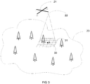
- the spraying area of each nozzle in the target area 23 may also be a gridded area.
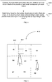
- 30 indicates a circle taking a projected point A of a nozzle 22 in the target area 23 as a center and taking a spraying width of the nozzle 22 as a radius.
- An outer-tangent rectangular area 31 and a plurality of grid areas in the outer-tangent rectangular area 31 are obtained by performing gridding processing on the circle 30, that is, the outer-tangent rectangular area 31 is a gridded area.
- the outer-tangent rectangular area 31 may be used as a spraying area of the nozzle 22 in the target area 23. Methods for determining spraying areas of other nozzles are similar to this and are not described one by one herein.
- the determining of the spraying area of each nozzle in the target area based on the location information of the unmanned aerial vehicle and the attitude information of the unmanned aerial vehicle includes: determining a spraying range of the unmanned aerial vehicle in the target area based on the location information of the unmanned aerial vehicle and a spraying width of the unmanned aerial vehicle; and determining, from the spraying range of the unmanned aerial vehicle in the target area, the spraying area of each nozzle in the target area based on the attitude information of the unmanned aerial vehicle.
- the location information of the unmanned aerial vehicle 21 may be the coordinate position of the unmanned aerial vehicle 21 in the three-dimensional space, and a spraying range of the unmanned aerial vehicle 21 in the target area 23 may be determined based on the coordinate position of the unmanned aerial vehicle 21 in the three-dimensional space and the spraying width of the unmanned aerial vehicle 21.
- the coordinate position of the unmanned aerial vehicle 21 in the three-dimensional space may be specifically a coordinate position of a central point of the unmanned aerial vehicle 21 in the three-dimensional space.
- the control device for the unmanned aerial vehicle 21 may determine a projected point of the central point of the unmanned aerial vehicle 21 in the target area 23 based on the coordinate position of the central point of the unmanned aerial vehicle 21 in the three-dimensional space.
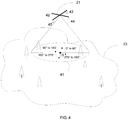
- the projected point is a point B.
- a circular area 41 taking the point B as a center and taking the spraying width of the unmanned aerial vehicle 21 as a radius may be specifically a spraying range of the unmanned aerial vehicle 21 in the target area 23.
- the spraying width of the unmanned aerial vehicle 21 may be fixed or adjustable.
- a shape of the spraying range of the unmanned aerial vehicle 21 in the target area 23 is not limited in this embodiment.
- FIG. 4 is merely an example for description.
- the shape of the spraying range of the unmanned aerial vehicle 21 in the target area 23 may also be a shape different from a circle.
- the control device may determine, from the spraying range, the spraying area corresponding to each nozzle based on the spraying range of the unmanned aerial vehicle 21 in the target area 23 and the attitude information of the unmanned aerial vehicle 21.
- the control device may determine, in a spraying range 41, a spraying area corresponding to each nozzle based on the attitude information of the unmanned aerial vehicle 21 and the mounting position of each nozzle on the unmanned aerial vehicle 21.
- a spraying area corresponding to the nozzle 43 in the spraying range 41 is a sectoral area in a range from 0° to 90° in the spraying range 41
- a spraying area corresponding to the nozzle 42 in the spraying range 41 is a sectoral area in a range from 90° to 180° in the spraying range 41
- a spraying area corresponding to the nozzle 45 in the spraying range 41 is a sectoral area in a range from 180° to 270° in the spraying range 41
- a spraying area corresponding to the nozzle 44 in the spraying range 41 is a sectoral area in a range from 270° to 360° in the spraying range 41.
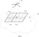
- the spraying area of each nozzle in the target area 23 may also be a gridded area.
- 51 indicates a circle taking a projected point B of the unmanned aerial vehicle 21 in the target area 23 as a center and taking the spraying width of the unmanned aerial vehicle 21 as a radius.
- An outer-tangent rectangular area and a plurality of grid areas in the outer-tangent rectangular area are obtained by performing gridding processing on the circle 51.
- the outer-tangent rectangular area may be used as a spraying range of the unmanned aerial vehicle 21 in the target area 23.
- a spraying area corresponding to each nozzle in the spraying range is determined based on the attitude information of the unmanned aerial vehicle 21 and the mounting position of each nozzle on the unmanned aerial vehicle 21.
- a spraying area corresponding to the nozzle 43 in the spraying range is a gridded area 413
- a spraying area corresponding to the nozzle 42 in the spraying range is a gridded area 412
- a spraying area corresponding to the nozzle 45 in the spraying range is a gridded area 415
- a spraying area corresponding to the nozzle 44 in the spraying range is a gridded area 414.
- each of the gridded area 412 to the gridded area 415 includes a plurality of grid areas, where the grid areas are grids indicated by dashed lines shown in FIG. 5 .
- Each of the gridded area 412 to the gridded area 415 is an area indicated by solid lines and including a plurality of grid areas.
- the spraying area of each nozzle in the target area 23 may also be a circular area, and the spraying area includes a plurality of grid areas.
- 60 indicates an outer-tangent rectangular area of a circle taking the projected point of the unmanned aerial vehicle 21 in the target area 23 as a center and taking the spraying width of the unmanned aerial vehicle 21 as a radius.
- a plurality of grid areas corresponding to the outer-tangent rectangular area 60 may be obtained by performing gridding processing on the outer-tangent rectangular area 60.
- the outer-tangent rectangular area 60 may be used as a spraying range of the unmanned aerial vehicle 21 in the target area 23.
- a spraying area corresponding to each nozzle in the spraying range is determined based on the attitude information of the unmanned aerial vehicle 21 and the mounting position of each nozzle on the unmanned aerial vehicle 21.
- a spraying area corresponding to the nozzle 43 in the spraying range is a circular area 63
- a spraying area corresponding to the nozzle 42 in the spraying range is a circular area 62
- a spraying area corresponding to the nozzle 45 in the spraying range is a circular area 65
- a spraying area corresponding to the nozzle 44 in the spraying range is a circular area 64.
- each of the circular area 63, the circular area 62, the circular area 65, and the circular area 64 includes a plurality of grid areas.
- FIG. 2 to FIG. 6 show several examples of determining the spraying area of each nozzle in the target area, and the present application is not specifically limited in this embodiment. Other existing methods for determining a spraying area of each nozzle in the target area or methods that may occur in the future may all be applied to this embodiment.
- Step S103 determining whether there are crops in the spraying area corresponding to each nozzle.
- the control device for the unmanned aerial vehicle 21 needs to further determine whether there are crops in the spraying area corresponding to each nozzle. Taking FIG. 5 as an example, the control device needs to determine whether there are crops in the spraying area 412, the spraying area 413, the spraying area 414, and the spraying area 415.
- Step S104 controlling the nozzle to be ON when it is determined that there are crops in the spraying area of the nozzle, otherwise controlling the nozzle to be OFF.
- control device for the unmanned aerial vehicle 21 determines that there are crops in the spraying area 412, the spraying area 413, and the spraying area 415 but there are no crops in the spraying area 414
- the control device may control the nozzle 42, the nozzle 43, and the nozzle 45 to be ON, and control the nozzle 44 to be OFF.
- controlling the nozzle to be ON when it is determined that there are crops in the spraying area of the nozzle, otherwise controlling the nozzle to be OFF includes: When it is determined that there are crops in the spraying area of the nozzle, sending a control instruction to a nozzle control system of the unmanned aerial vehicle, where the control instruction is used to control the nozzle to be ON; or When it is determined that there are no crops in the spraying area of the nozzle, sending a control instruction to a nozzle control system of the unmanned aerial vehicle, where the control instruction is used to control the nozzle to be OFF.
- ON or OFF of the nozzle on the unmanned aerial vehicle 21 is controlled by the nozzle control system of the unmanned aerial vehicle 21.
- the control device for the unmanned aerial vehicle 21 sends a control instruction to the nozzle control system of the unmanned aerial vehicle 21, where the control instruction is used to control the nozzle 42, the nozzle 43, and the nozzle 45 to be ON; and after receiving the control instruction, the nozzle control system turns on the nozzle 42, the nozzle 43, and the nozzle 45.
- the control device for the unmanned aerial vehicle 21 sends a control instruction to the nozzle control system of the unmanned aerial vehicle 21, where the control instruction is used to control the nozzle 44 to be OFF; and after receiving the control instruction, the nozzle control system turns off the nozzle 44.
- the spraying area of each nozzle in the target area based on the location information of the unmanned aerial vehicle and the attitude information of the unmanned aerial vehicle and further determining whether there are crops in the spraying area corresponding to each nozzle, which nozzle corresponds to a spraying area with crops and which nozzle corresponds to a spraying area without crops can be determined; and if there are crops in the spraying area of a nozzle, the nozzle is controlled to be ON, otherwise, the nozzle is controlled to be OFF. Therefore, waste of pesticide can be effectively avoided in comparison with an operation mode of turning on all nozzles of an unmanned aerial vehicle to spray simultaneously.
- FIG. 7 is a flowchart of a method for controlling an unmanned aerial vehicle according to another embodiment of the present invention.
- the determining whether there are crops in the spraying area corresponding to each nozzle includes: Step S701: obtaining a distribution status diagram of crops in the target area, where the distribution status diagram of crops in the target area is determined based on an image captured by a surveying and mapping unmanned aerial vehicle in a process of flying in the target area.
- the distribution status diagram of crops in the target area is determined based on three-dimensional point cloud information of the target area, and the three-dimensional point cloud information of the target area is generated based on the image captured by the surveying and mapping unmanned aerial vehicle in the process of flying in the target area.
- the surveying and mapping unmanned aerial vehicle may fly in the target area 23 before the unmanned aerial vehicle 21 such as the agricultural unmanned aerial vehicle performs the spraying task in the target area 23, the surveying and mapping unmanned aerial vehicle may fly in the target area 23.
- the surveying and mapping unmanned aerial vehicle may shoot images in real-time, where each image may be an image of a part of the target area 23.
- the surveying and mapping unmanned aerial vehicle may record location information of the surveying and mapping unmanned aerial vehicle and attitude information of a gimbal of the surveying and mapping unmanned aerial vehicle when shooting each image. To be specific, for each image, there are corresponding location information of the surveying and mapping unmanned aerial vehicle and attitude information of the gimbal.
- Each image shot by the surveying and mapping unmanned aerial vehicle and the location information of the surveying and mapping unmanned aerial vehicle and the attitude information of the gimbal that correspond to each image may be stored in a built-in memory or an external memory of the surveying and mapping unmanned aerial vehicle.
- SD card secure digital memory card
- the user may remove the SD card from the surveying and mapping unmanned aerial vehicle, and insert the SD card into a computer, for example, a personal computer (PC).
- PC personal computer
- the computer may read each image, and the location information of the surveying and mapping unmanned aerial vehicle and the attitude information of the gimbal that correspond to each image that are stored in the SD card, and further generate, based on each image, and the location information of the surveying and mapping unmanned aerial vehicle and the attitude information of the gimbal that correspond to each image, a three-dimensional point cloud corresponding to the target area 23, where each three-dimensional point in the three-dimensional point cloud may correspond to three-dimensional coordinates and color information. Further, the computer generates the distribution status diagram of crops in the target area 23 based on the three-dimensional point cloud corresponding to the target area 23.
- the personal computer may input the three-dimensional point cloud information to a neural network model that is well trained beforehand, where the neural network model that is well trained beforehand may perform recognition on the three-dimensional point cloud information to output the distribution status diagram of crops in the target area 23.
- the distribution status diagram of crops in the target area 23 may be a semantic map of the target area.
- Step S702 querying, from the distribution status diagram, whether there are crops in the spraying area corresponding to each nozzle.
- the unmanned aerial vehicle 21 when the unmanned aerial vehicle 21 such as the agricultural unmanned aerial vehicle performs the spraying task in the target area 23, the unmanned aerial vehicle 21 may pre-store the distribution status diagram.
- the control device determines the spraying area of each nozzle of the unmanned aerial vehicle 21 in the target area 23, the control device may query, from the distribution status diagram, whether there are crops in the spraying area of each nozzle in the target area 23.
- the spraying area includes a plurality of grid areas
- the querying, from the distribution status diagram, whether there are crops in the spraying area corresponding to each nozzle includes the following steps, as shown in FIG. 8 .
- Step S801 querying, from the distribution status diagram, whether there are crops in each of the plurality of grid areas corresponding to each nozzle.
- the spraying area of each nozzle in the target area 23 includes a plurality of grid areas.
- the control device may first query, from the distribution status diagram, whether there are crops in each of the plurality of grid areas corresponding to the spraying area of each nozzle in the target area 23.
- the control device may query, from the distribution status diagram, whether there are crops in each of nine grid areas corresponding to the spraying area 413.
- the distribution status diagram of crops in the target area includes location information of each unit area in the target area and identification information corresponding to each unit area, where the identification information is used to indicate whether there are crops in the unit area, and the grid area is larger than or equal to the unit area.
- the computer generates the distribution status diagram of crops in the target area 23 based on the three-dimensional point cloud corresponding to the target area 23.
- the computer may input the three-dimensional point cloud to the neural network model that is well trained beforehand, and the neural network model may recognize whether there are crops in each unit area in the target area 23.
- the target area 23 may be an area in the three-dimensional space, and each unit area in the target area 23 is also an area in the three-dimensional space.
- the target area 23 may be formed by unit areas, where the unit area may be, for example, an area of 1 cubic centimeter.
- the neural network may output three-dimensional coordinates of a geometric center of each unit area and the identification information corresponding to each unit area, where the identification information is used to indicate whether there are crops in the unit area.
- the identification information may indicate that there are objects such as fruit trees, a utility pole, a pool, or weeds in the unit area. The fruit trees are crops to be sprayed, but the utility pole, the pool, or weeds are not crops to be sprayed.
- the distribution status diagram of the target area 23 includes the three-dimensional coordinates of the geometric center of each unit area in the target area 23 and the identification information corresponding to each unit area.
- the plurality of grid areas corresponding to each nozzle as shown in FIG. 5 may also be areas in the three-dimensional space.
- each grid area is larger than or equal to the unit area.
- each grid area may be an area of 1 cubic meter. Therefore, each grid area may include a plurality of unit areas.
- the querying of whether there are crops in each of the plurality of grid areas corresponding to each nozzle from the distribution status diagram includes: determining, based on the location information of each unit area included in the distribution status diagram and location information of each of the plurality of grid areas corresponding to each nozzle, unit areas covered by each of the plurality of grid areas corresponding to each nozzle; determining the number of unit areas whose identification information is target identification information, in the unit areas covered by each of the plurality of grid areas corresponding to each nozzle; and determining, based on the number, whether there are crops in each of the plurality of grid areas corresponding to each nozzle.
- the target area, the unit area, and the grid area may also be areas in a plane.
- each grid area may be an area of 1 square meter
- each unit area may be an area of 1 square centimeter
- each grid area may include a plurality of unit areas.
- the spraying area 413 includes nine grid areas, which are a grid area 81 to a grid area 89 in sequence, as shown in FIG. 9 .
- the control device for the unmanned aerial vehicle 21 queries, from the distribution status diagram, whether there are crops in each of the nine grid areas corresponding to the nozzle 43, the control device may determine, based on the location information of each unit area included in the distribution status diagram and location information of each of the nine grid areas, unit areas covered by each of the nine grid areas.
- the grid area 82 covers a plurality of unit areas, where 821 indicates any one of the plurality of unit areas.
- Each of the plurality of unit areas covered by the grid area 82 corresponds to one piece of identification information, where the identification information may be used to indicate whether there are crops in the unit area.
- identification information used to indicate that there are crops in a unit area may be marked as target identification information. Therefore, the number of unit areas whose identification information is target identification information, in the plurality of unit areas covered by the grid area 82 may be counted, that is, the number of unit areas having crops, in the plurality of unit areas covered by the grid area 82 is counted. As shown in FIG.
- identification information corresponding to a unit area 822 in the plurality of unit areas covered by the grid area 82 is the target identification information, that is, in the plurality of unit areas covered by the grid area 82, the number of unit areas whose corresponding identification information is the target identification information is 1. That is, in the plurality of unit areas covered by the grid area 82, the number of unit areas having crops is 1.
- the number of unit areas having crops may be counted. Further, based on the number of unit areas having crops, in the plurality of unit areas covered by each of the grid area 81 to the grid area 89, whether there are crops in each of the nine grid areas is determined.
- the determining of whether there are crops in each of the plurality of grid areas corresponding to each nozzle based on the number includes: in the unit areas covered by the grid area, if the number of unit areas whose identification information is target identification information is greater than or equal to 1, determining that there are crops in the grid area, otherwise determining that there are no crops in the grid area.
- the number of unit areas whose corresponding identification information is the target identification information is 1, and it may be determined that there are crops in the grid area 82.
- the number of unit areas whose corresponding identification information is the target identification information is 0, and it is determined that there are no crops in the grid area 83.
- each grid area only when the number of unit areas whose corresponding identification information is the target identification information is greater than or equal to a preset value, it can be considered that there are crops in the grid area.
- the preset value may be a positive integer greater than 1, or may be a percentage. For example, if the grid area 82 covers 100 unit areas, it is considered that there are crops in the grid area 82 only when identification information of 10% or more of the 100 unit areas is the target identification information.
- 10% is only an example, and other values may also be used.
- Step S802 determining, based on the number of grid areas having crops, in the plurality of grid areas corresponding to each nozzle, whether there are crops in the spraying area corresponding to each nozzle.
- the number of grid areas having crops may be determined.
- the determining, based on the number of grid areas having crops, in the plurality of grid areas corresponding to each nozzle, whether there are crops in the spraying area corresponding to each nozzle includes: if the number of grid areas having crops, in the plurality of grid areas corresponding to the nozzle, is greater than or equal to 1, determining that there are crops in the spraying area corresponding to the nozzle, otherwise determining that there are no crops in the spraying area corresponding to the nozzle.
- the control device for the unmanned aerial vehicle may determine, based on the number of grid areas having crops, in the plurality of grid areas in the spraying area corresponding to each nozzle, whether there are crops in the spraying area corresponding to each nozzle.
- the number of grid areas having crops, in the plurality of grid areas in the spraying area corresponding to the nozzle is greater than or equal to 1, it is determined that there are crops in the spraying area corresponding to the nozzle, otherwise, it is determined that there are no crops in the spraying area corresponding to the nozzle. As shown in FIG.
- the unmanned aerial vehicle can control the nozzle 43, the nozzle 42, and the nozzle 45 to be ON, and control the nozzle 44 to be OFF.
- the surveying and mapping unmanned aerial vehicle before the agricultural unmanned aerial vehicle performs the spraying task in the target area, the surveying and mapping unmanned aerial vehicle performs photographing on the target area, to obtain a plurality of images corresponding to the target area, location information of the surveying and mapping unmanned aerial vehicle and attitude information of the gimbal corresponding to each image, and may determine the distribution status diagram of crops in the target area based on each image, and the location information of the surveying and mapping unmanned aerial vehicle and the attitude information of the gimbal corresponding to each image.
- the agricultural unmanned aerial vehicle may query, from the distribution status diagram, whether there are crops in the spraying area corresponding to each nozzle. This improves the accuracy of determining whether there are crops in the spraying area corresponding to each nozzle, further improves the accuracy of controlling the nozzle, and therefore avoids waste of pesticide more effectively.
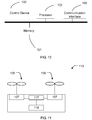
- FIG. 10 is a structural diagram of a control device for an unmanned aerial vehicle according to an embodiment of the present invention.
- a plurality of nozzles are disposed on the unmanned aerial vehicle, and the nozzles are configured to perform a spraying task on crops in a target area.
- the control device 100 includes a memory 101 and a processor 102.
- the memory 101 is configured to store program code.
- the processor 102 is configured to invoke the program code, and configured to perform the following operations when the program code is executed: obtaining location information and attitude information of the unmanned aerial vehicle; determining a spraying area of each nozzle in the target area based on the location information of the unmanned aerial vehicle and the attitude information of the unmanned aerial vehicle; determining whether there are crops in the spraying area corresponding to each nozzle; and When it is determined that there are crops in the spraying area of the nozzle, controlling the nozzle to be ON, otherwise controlling the nozzle to be OFF.
- the processor 102 when determining the spraying area of each nozzle in the target area based on the location information of the unmanned aerial vehicle and the attitude information of the unmanned aerial vehicle, is specifically configured to: determine location information of each nozzle based on the location information of the unmanned aerial vehicle and the attitude information of the unmanned aerial vehicle; and determine the spraying area of each nozzle in the target area based on the location information of each nozzle and a spraying width of each nozzle.
- the processor 102 when determining the spraying area of each nozzle in the target area based on the location information of the unmanned aerial vehicle and the attitude information of the unmanned aerial vehicle, is specifically configured to: determine a spraying range of the unmanned aerial vehicle in the target area based on the location information of the unmanned aerial vehicle and a spraying width of the unmanned aerial vehicle; and determine, from the spraying range of the unmanned aerial vehicle in the target area, the spraying area of each nozzle in the target area based on the attitude information of the unmanned aerial vehicle.
- the processor 102 when determining whether there are crops in the spraying area corresponding to each nozzle, is specifically configured to: obtain a distribution status diagram of crops in the target area, where the distribution status diagram of crops in the target area is determined based on an image captured by a surveying and mapping unmanned aerial vehicle in a process of flying in the target area; and query, from the distribution status diagram, whether there are crops in the spraying area corresponding to each nozzle.
- the distribution status diagram of crops in the target area is determined based on three-dimensional point cloud information of the target area, and the three-dimensional point cloud information of the target area is generated based on the image captured by the surveying and mapping unmanned aerial vehicle in the process of flying in the target area.
- the spraying area includes a plurality of grid areas, and when querying, from the distribution status diagram, whether there are crops in the spraying area corresponding to each nozzle, the processor 102 is specifically configured to: query, from the distribution status diagram, whether there are crops in each of the plurality of grid areas corresponding to each nozzle; and determine, based on the number of grid areas having crops, in the plurality of grid areas corresponding to each nozzle, whether there are crops in the spraying area corresponding to each nozzle.
- the processor 102 when determining, based on the number of grid areas having crops, in the plurality of grid areas corresponding to each nozzle, whether there are crops in the spraying area corresponding to each nozzle, the processor 102 is specifically configured to: if the number of grid areas having crops, in the plurality of grid areas corresponding to the nozzle is greater than or equal to 1, determine that there are crops in the spraying area corresponding to the nozzle, otherwise determine that there are no crops in the spraying area corresponding to the nozzle.
- the distribution status diagram of crops in the target area includes location information of each unit area in the target area and identification information corresponding to each unit area, where the identification information is used to indicate whether there are crops in the unit area, and the grid area is larger than or equal to the unit area; and when querying, from the distribution status diagram, whether there are crops in each of the plurality of grid areas corresponding to each nozzle, the processor 102 is specifically configured to: determine, based on the location information of each unit area included in the distribution status diagram and location information of each of the plurality of grid areas corresponding to each nozzle, unit areas covered by each of the plurality of grid areas corresponding to each nozzle; determine the number of unit areas whose identification information is target identification information, in the unit areas covered by each of the plurality of grid areas corresponding to each nozzle; and determine, based on the number, whether there are crops in each of the plurality of grid areas corresponding to each nozzle.
- the processor 102 when determining, based on the number, whether there are crops in each of the plurality of grid areas corresponding to each nozzle, is specifically configured to: if the number of unit areas whose identification information is target identification information, in the unit areas covered by the grid area is greater than or equal to 1, determine that there are crops in the grid area, otherwise determine that there are no crops in the grid area.
- the control device further includes a communication interface 103.
- the processor 102 is specifically configured to: when the processor 102 determines that there are crops in the spraying area of the nozzle, send a control instruction to a nozzle control system of the unmanned aerial vehicle by using the communication interface 103, where the control instruction is used to control the nozzle to be ON; or when the processor 102 determines that there are no crops in the spraying area of the nozzle, send a control instruction to a nozzle control system of the unmanned aerial vehicle by using the communication interface, where the control instruction is used to control the nozzle to be OFF.
- control device provided in this embodiment of the present invention are similar to those in the foregoing embodiment. Details are not described again herein.
- An embodiment of the present invention provides a spraying system of an unmanned aerial vehicle.
- the unmanned aerial vehicle performs a spraying task on crops in a target area.
- the spraying system of the unmanned aerial vehicle includes: a plurality of nozzles, a nozzle control system, and the control device in the foregoing embodiment, where the plurality of nozzles are mounted on a fuselage of the unmanned aerial vehicle; and the nozzle control system is configured to control the plurality of nozzles to be ON or OFF.
- Specific principles and implementations of the control device are similar to those in the foregoing embodiment. Details are not described again herein.
- FIG. 11 is a structural diagram of an unmanned aerial vehicle according to an embodiment of the present invention.
- the unmanned aerial vehicle 110 includes a fuselage, a power system, and a flight controller 118.
- the power system includes at least one of the following: a motor 107, a propeller 106, and an electronic speed governor 117.
- the power system is mounted in the fuselage, and configured to supply power for flying.
- the flight controller 118 is communicatively connected to the power system, and is configured to control the flight of the unmanned aerial vehicle.
- the unmanned aerial vehicle 110 may further include the foregoing spraying system of the unmanned aerial vehicle. Specific principles and implementations of the spraying system of the unmanned aerial vehicle are similar to those in the foregoing embodiment. Details are not described again herein.
- the unmanned aerial vehicle 110 is an agricultural unmanned aerial vehicle.
- this embodiment further provides a computer-readable storage medium, where the computer-readable storage medium stores a computer program thereon, and the computer program is executed by a processor to implement the method for controlling an unmanned aerial vehicle in the foregoing embodiment.
- the disclosed apparatus and method may be implemented in other manners.
- the described apparatus embodiment is merely an example.
- the unit division is merely logical function division and may be other division in actual implementation.
- a plurality of units or components may be combined or integrated into another system, or some features may be ignored or may not be performed.
- the displayed or discussed mutual couplings or direct couplings or communication connections may be implemented by using some interfaces.
- the indirect couplings or communication connections between the apparatuses or units may be implemented in electronic, mechanical, or other forms.
- the units described as separate parts may or may not be physically separate, and parts displayed as units may or may not be physical units, may be located in one position, or may be distributed on a plurality of network elements. Some or all of the units may be selected based on actual requirements to achieve the objectives of the solutions of the embodiments.
- functional units in the embodiments of the present invention may be integrated into one processing unit, or each of the units may exist alone physically, or two or more units are integrated into one unit.
- the integrated unit may be implemented in a form of hardware or may be implemented in a form of hardware in addition to a software functional unit.
- the integrated unit may be stored in a computer-readable storage medium.
- the software functional unit is stored in a storage medium and includes several instructions for instructing a computer device (which may be a personal computer, a server, a network device, or the like) or a processor to perform a part of the steps of the methods described in the embodiments of the present invention.
- the foregoing storage medium includes: any medium that can store program code, such as a USB flash drive, a removable hard disk, a read-only memory (ROM), a random-access memory (RAM), a magnetic disk, or an optical disc.
Landscapes
- Life Sciences & Earth Sciences (AREA)
- Engineering & Computer Science (AREA)
- Pest Control & Pesticides (AREA)
- Environmental Sciences (AREA)
- Zoology (AREA)
- Insects & Arthropods (AREA)
- Wood Science & Technology (AREA)
- Aviation & Aerospace Engineering (AREA)
- Radar, Positioning & Navigation (AREA)
- Remote Sensing (AREA)
- Physics & Mathematics (AREA)
- General Physics & Mathematics (AREA)
- Automation & Control Theory (AREA)
- Soil Sciences (AREA)
- Mechanical Engineering (AREA)
- Catching Or Destruction (AREA)
- Control Of Position, Course, Altitude, Or Attitude Of Moving Bodies (AREA)
Applications Claiming Priority (1)
| Application Number | Priority Date | Filing Date | Title |
|---|---|---|---|
| PCT/CN2019/084979 WO2020220195A1 (fr) | 2019-04-29 | 2019-04-29 | Procédé de commande de véhicule aérien sans pilote, dispositif et système de pulvérisation et véhicule aérien sans pilote et support d'informations |
Publications (2)
| Publication Number | Publication Date |
|---|---|
| EP3859480A1 true EP3859480A1 (fr) | 2021-08-04 |
| EP3859480A4 EP3859480A4 (fr) | 2021-11-24 |
Family
ID=72646400
Family Applications (1)
| Application Number | Title | Priority Date | Filing Date |
|---|---|---|---|
| EP19926779.0A Withdrawn EP3859480A4 (fr) | 2019-04-29 | 2019-04-29 | Procédé de commande de véhicule aérien sans pilote, dispositif et système de pulvérisation et véhicule aérien sans pilote et support d'informations |
Country Status (4)
| Country | Link |
|---|---|
| US (1) | US20210101682A1 (fr) |
| EP (1) | EP3859480A4 (fr) |
| CN (1) | CN111741897A (fr) |
| WO (1) | WO2020220195A1 (fr) |
Families Citing this family (10)
| Publication number | Priority date | Publication date | Assignee | Title |
|---|---|---|---|---|
| CA3035225A1 (fr) * | 2019-02-28 | 2020-08-28 | Daniel Mccann | Systeme et procede pour la surveillance et le traitement sur le terrain |
| CN112206441B (zh) * | 2020-10-12 | 2022-02-08 | 江西省智能产业技术创新研究院 | 一种消防机器人调度系统的协同调度方法 |
| CN112327911B (zh) * | 2020-10-29 | 2023-08-18 | 浙江万里学院 | 一种无人机农药喷洒控制方法及无人机 |
| CN112455690A (zh) * | 2021-01-25 | 2021-03-09 | 杭州明本玩具有限公司 | 一种可自动检测高度全方位喷洒农药的无人机 |
| CN116783118A (zh) * | 2021-01-28 | 2023-09-19 | 深圳市大疆创新科技有限公司 | 一种喷洒控制方法、设备、植保无人机及存储介质 |
| CN113002778B (zh) * | 2021-03-09 | 2022-06-07 | 温州市勘察测绘研究院有限公司 | 一种无人机航拍测绘的标靶像控点布设系统 |
| CN113349038B (zh) * | 2021-06-30 | 2023-03-24 | 广州极飞科技股份有限公司 | 一种灌溉作业控制方法、装置、存储介质及灌溉设备 |
| CN113749078B (zh) * | 2021-08-16 | 2023-04-21 | 北京农业智能装备技术研究中心 | 一种多路喷头独立控制方法及系统 |
| CN113826598A (zh) * | 2021-09-10 | 2021-12-24 | 宁波权智科技有限公司 | 一种基于神经网络的无人机撒药方法及装置 |
| CN114403116B (zh) * | 2022-02-13 | 2023-06-30 | 厦门精图信息技术有限公司 | 基于北斗网格位置码的智慧林草管理系统 |
Family Cites Families (17)
| Publication number | Priority date | Publication date | Assignee | Title |
|---|---|---|---|---|
| JP2008068711A (ja) * | 2006-09-13 | 2008-03-27 | Yamaha Motor Co Ltd | 無人ヘリコプタの飛行支援方法および飛行支援装置 |
| US11130573B2 (en) * | 2015-11-02 | 2021-09-28 | Aerovironment, Inc. | Disbursement system for an unmanned aerial vehicle |
| CN106714554B (zh) * | 2016-04-29 | 2019-04-09 | 深圳市大疆创新科技有限公司 | 无人机的喷洒控制方法和无人机 |
| CN105905302B (zh) * | 2016-06-02 | 2017-11-10 | 中国农业大学 | 一种植保无人机智能施药系统及控制方法 |
| US9856020B1 (en) * | 2016-07-27 | 2018-01-02 | International Business Machines Corporation | Drone-based mosquito amelioration based on risk analysis and pattern classifiers |
| CN106167098B (zh) * | 2016-09-07 | 2018-09-25 | 南京林业大学 | 一种基于立体测量的旋翼无人机自动施药系统与方法 |
| CN106335641A (zh) * | 2016-09-21 | 2017-01-18 | 江西天祥通用航空股份有限公司 | 一种飞机智能喷洒方法及系统 |
| CN107161346B (zh) * | 2017-05-18 | 2020-10-20 | 浙江大学 | 一种基于遍历航点的无人机喷药系统及喷药方法 |
| CN108475069B (zh) * | 2017-05-22 | 2021-06-22 | 深圳市大疆创新科技有限公司 | 农业无人飞行器的控制方法、飞行控制器及农业无人机 |
| WO2018216214A1 (fr) * | 2017-05-26 | 2018-11-29 | 株式会社オプティム | Système, procédé et programme de pulvérisation de pesticide conforme aux gap |
| CN108519775B (zh) * | 2017-10-30 | 2021-04-06 | 北京博鹰通航科技有限公司 | 一种精准喷洒的无人机系统及其控制方法 |
| CN109073375A (zh) * | 2017-12-18 | 2018-12-21 | 深圳市大疆创新科技有限公司 | 喷洒面积的测量方法和设备 |
| CN109271862A (zh) * | 2018-08-15 | 2019-01-25 | 广州极飞科技有限公司 | 基于移动装置的喷洒控制方法及终端、移动装置 |
| CN109324630A (zh) * | 2018-09-19 | 2019-02-12 | 清远市飞凡创丰科技有限公司 | 一种无人机喷药系统及控制方法 |
| CN109358643B (zh) * | 2018-10-31 | 2022-09-02 | 阮镇荣 | 一种基于图像处理的多模式无人机农药喷洒系统及方法 |
| CN109329252A (zh) * | 2018-11-27 | 2019-02-15 | 山东理工大学 | 基于农机农艺融合的双臂篱架式葡萄园航空施药作业方法 |
| CN109533339B (zh) * | 2019-01-09 | 2021-03-30 | 内蒙古安宏科技有限公司 | 一种抑尘无人机及使用该无人机的抑尘方法 |
-
2019
- 2019-04-29 WO PCT/CN2019/084979 patent/WO2020220195A1/fr not_active Ceased
- 2019-04-29 EP EP19926779.0A patent/EP3859480A4/fr not_active Withdrawn
- 2019-04-29 CN CN201980012486.1A patent/CN111741897A/zh active Pending
-
2020
- 2020-12-17 US US17/125,672 patent/US20210101682A1/en not_active Abandoned
Also Published As
| Publication number | Publication date |
|---|---|
| US20210101682A1 (en) | 2021-04-08 |
| EP3859480A4 (fr) | 2021-11-24 |
| WO2020220195A1 (fr) | 2020-11-05 |
| CN111741897A (zh) | 2020-10-02 |
Similar Documents
| Publication | Publication Date | Title |
|---|---|---|
| EP3859480A1 (fr) | Procédé de commande de véhicule aérien sans pilote, dispositif et système de pulvérisation et véhicule aérien sans pilote et support d'informations | |
| US11776413B2 (en) | Aerial vehicle flight control method and device thereof | |
| US11908207B2 (en) | Method for detecting road diseases by intelligent cruise via unmanned aerial vehicle, unmanned aerial vehicle and detecting system therefor | |
| RU2768997C1 (ru) | Способ, устройство и оборудование для распознавания препятствий или земли и управления полетом, и носитель данных | |
| CN107765709B (zh) | 基于飞行器实现自拍的方法及装置 | |
| US20190278303A1 (en) | Method of controlling obstacle avoidance for unmanned aerial vehicle and unmanned aerial vehicle | |
| CN107933921A (zh) | 飞行器及其喷洒路线生成和执行方法、装置、控制终端 | |
| WO2018094583A1 (fr) | Procédé de commande d'évitement d'obstacle de véhicule aérien sans pilote, dispositif de commande de vol, et véhicule aérien sans pilote | |
| CN109035871A (zh) | 无人机飞行路线规划方法、装置、系统及智能终端 | |
| WO2018210078A1 (fr) | Procédé de mesure de distance pour un véhicule aérien sans pilote et véhicule aérien sans pilote | |
| CN109074089B (zh) | 无人机的控制方法、飞行控制器及无人机 | |
| CN109407701B (zh) | 控制作业的方法、系统及装置 | |
| WO2020103108A1 (fr) | Procédé et dispositif de génération de sémantique, drone et support d'informations | |
| WO2019100188A1 (fr) | Procédé de planification d'un itinéraire de fonctionnement d'un véhicule aérien sans pilote et dispositif d'extrémité de sol | |
| CN110618691A (zh) | 基于机器视觉的无人机同心圆靶精准降落方法 | |
| WO2022087905A1 (fr) | Procédé et dispositif de commande de fonctionnement ainsi que véhicule aérien sans pilote et support de stockage lisible par ordinateur | |
| JPWO2017203646A1 (ja) | 撮像制御装置、影位置特定装置、撮像システム、移動体、撮像制御方法、影位置特定方法、及びプログラム | |
| JP2020170213A (ja) | ドローン作業支援システム及びドローン作業支援方法 | |
| US20240427347A1 (en) | Aircraft control method and apparatus, aircraft, and storage medium | |
| CN118486198B (zh) | 基于区域划分的无人机交通控制方法、设备及介质 | |
| CN114740885A (zh) | 一种无人机返航方法、装置、设备及存储介质 | |
| CN114041097B (zh) | 无人飞行器的航线平滑处理方法、装置及控制终端 | |
| CN206202675U (zh) | 无人飞行器 | |
| KR102267022B1 (ko) | 액제 혹은 입제를 변량 살포하기 위한 드론 | |
| JP2020091201A (ja) | コンピュータシステムおよびデータ構造 |
Legal Events
| Date | Code | Title | Description |
|---|---|---|---|
| STAA | Information on the status of an ep patent application or granted ep patent |
Free format text: STATUS: THE INTERNATIONAL PUBLICATION HAS BEEN MADE |
|
| PUAI | Public reference made under article 153(3) epc to a published international application that has entered the european phase |
Free format text: ORIGINAL CODE: 0009012 |
|
| STAA | Information on the status of an ep patent application or granted ep patent |
Free format text: STATUS: REQUEST FOR EXAMINATION WAS MADE |
|
| 17P | Request for examination filed |
Effective date: 20201216 |
|
| AK | Designated contracting states |
Kind code of ref document: A1 Designated state(s): AL AT BE BG CH CY CZ DE DK EE ES FI FR GB GR HR HU IE IS IT LI LT LU LV MC MK MT NL NO PL PT RO RS SE SI SK SM TR |
|
| A4 | Supplementary search report drawn up and despatched |
Effective date: 20211021 |
|
| RIC1 | Information provided on ipc code assigned before grant |
Ipc: B64D 1/18 20060101ALN20211015BHEP Ipc: G05D 1/00 20060101ALI20211015BHEP Ipc: B64C 39/02 20060101ALI20211015BHEP Ipc: B05B 13/00 20060101ALI20211015BHEP Ipc: B05B 12/12 20060101ALI20211015BHEP Ipc: B05B 12/04 20060101ALI20211015BHEP Ipc: A01M 7/00 20060101ALI20211015BHEP Ipc: A01B 79/00 20060101AFI20211015BHEP |
|
| DAV | Request for validation of the european patent (deleted) | ||
| DAX | Request for extension of the european patent (deleted) | ||
| STAA | Information on the status of an ep patent application or granted ep patent |
Free format text: STATUS: THE APPLICATION IS DEEMED TO BE WITHDRAWN |
|
| 18D | Application deemed to be withdrawn |
Effective date: 20220520 |