EP3859481A1 - Procédé d'amélioration de la qualité de la navigation par conception active des informations de mouvement d'un groupe collaborant d'unités mobiles sans équipage - Google Patents
Procédé d'amélioration de la qualité de la navigation par conception active des informations de mouvement d'un groupe collaborant d'unités mobiles sans équipage Download PDFInfo
- Publication number
- EP3859481A1 EP3859481A1 EP20215907.5A EP20215907A EP3859481A1 EP 3859481 A1 EP3859481 A1 EP 3859481A1 EP 20215907 A EP20215907 A EP 20215907A EP 3859481 A1 EP3859481 A1 EP 3859481A1
- Authority
- EP
- European Patent Office
- Prior art keywords
- mobile units
- mobile
- units
- swarm
- network structure
- Prior art date
- Legal status (The legal status is an assumption and is not a legal conclusion. Google has not performed a legal analysis and makes no representation as to the accuracy of the status listed.)
- Withdrawn
Links
Images
Classifications
-
- G—PHYSICS
- G05—CONTROLLING; REGULATING
- G05D—SYSTEMS FOR CONTROLLING OR REGULATING NON-ELECTRIC VARIABLES
- G05D1/00—Control of position, course, altitude or attitude of land, water, air or space vehicles, e.g. using automatic pilots
- G05D1/10—Simultaneous control of position or course in three dimensions
- G05D1/101—Simultaneous control of position or course in three dimensions specially adapted for aircraft
- G05D1/104—Simultaneous control of position or course in three dimensions specially adapted for aircraft involving a plurality of aircrafts, e.g. formation flying
Definitions
- the present invention relates to a method for improving a navigation quality by actively shaping a movement formation of a collaborative swarm of mobile unmanned units.
- the present invention relates in particular to a method for designing a flight formation of a collaborative swarm of drones.
- UAS flight systems
- DAS Defense Advanced Research Projects Agency
- CODE Cold-Edge Environment
- the mission design can be defined very variably in these and similar applications and vary from simple adherence to formation to more complex tasks, which can include, for example, the interactions with targets and / or the environment.
- the design of a swarm constellation or swarm formation has typically taken place without taking into account the navigation aspects of the mobile units. Rather, position information often serves as the basis for coordinating the mobile units, which are provided by external tracking and / or positioning sensors (e.g. from a global navigation satellite system, GNSS) and / or an external system controller. In real application scenarios, however, the connection to such information sources can be at least temporarily suspended.
- GNSS global navigation satellite system
- the pamphlets EP 2 184 617 A3 , EP 2 730 887 B1 and EP 2 749 842 A1 describe, for example, systems and methods for the collaborative navigation of unmanned mobile units.
- the present invention is based on the task of finding more robust and at the same time precise solutions for constellation design of swarms of mobile unmanned units.
- this object is achieved by a method with the features of claim 1 and by a swarm of a multiplicity of mobile unmanned units with the features of claim 13.
- a method for improving a navigation quality by actively designing a movement formation of a collaborative swarm of mobile unmanned units, in particular a flight formation of a swarm of drones.
- Each mobile unit has: a position sensor system which is designed to determine a current absolute position of the respective mobile unit and current relative measurements of at least neighboring mobile units with respect to the respective mobile unit in the movement formation; a communication unit for data communication between the respective mobile unit and the other mobile units via a wireless swarm network; and a flight control unit which is designed to command and implement a movement of the respective mobile unit.
- the method comprises assuming a basic network structure by the mobile units within the movement formation, the basic network structure defining a relative basic geometric arrangement in the positioning of the mobile units within the movement formation; continuous mutual determination by the mobile units of the current relative measurements of the mobile units; dynamic adjustment of current relative positions by the mobile units in accordance with the basic network structure; and changing the positions of the mobile units in the movement formation in compliance with the basic network structure, the current relative measurements being determined again after or during each repositioning, a determination of the absolute positions of the mobile units being specified based on the newly determined current relative measurements.
- each mobile unit also having a control device which is designed to control the respective mobile unit in communication with the remaining mobile unit via the swarm network for carrying out the method according to the invention.
- One idea on which the present invention is based is to significantly improve the navigation quality and navigation robustness of a collaborative swarm by, on the one hand, imposing an advantageous basic geometric constellation on the network and, on the other hand, performing multiple position changes within this basic constellation in order to improve the additional position information obtained in this way the positional accuracy of the conquered formation.
- the mobile units are each independently able to record absolute positions and relative positions / orientations, so that temporary or long-lasting malfunction and / or failure phases of an external control and / or navigation system can be overcome in a robust manner.
- the system according to the invention can thus implement navigation practically independently of global navigation satellite systems or similar external sensors.
- the approach according to the invention combines a constellation finding optimized for navigation with a dynamic, ie active, adaptation of the same.
- measurements of one or more inertial measurement units (IMU) and mutual measurements of the mobile units can be used together with an appropriately chosen basic network structure (i.e. a geometric constellation definition) in order to significantly improve position estimates of the individual mobile units and thus the overall formation and minimize the resulting uncertainties to keep.
- the geometric constellation of the individual mobile units can be designed in such a way that the overall result is improved navigation performance and increased robustness for the overall system and thus ultimately also for individual mobile units.
- the individual units are viewed as separate navigation units and generally have an inertial or otherwise defined basic sensor system including additional support sensors that are used, among other things, for mutual measurement.
- This information can be exchanged between the mobile units via the swarm network, so that the current status changes of the individual units and the mutual measurements are available in the overall system and can be continuously updated.
- Such status information includes at least the measured or estimated absolute positions of the individual units, but can be supplemented by further components such as speed, position angle, etc. with associated uncertainties.
- Inaccuracies in the position can arise in particular due to sensor drifts of the corresponding inertial sensors used, which increase over time.
- the absolute positions determined with an IMU are thus typically subject to an error and thus differ from the actual, physical positions of the respective unit.
- the mutual measurements of the units take place from the actual position of the units.
- Direction vectors which result, for example, from the mutual measurements, thus point in particular to the true positions of the units (neglecting the errors of the sensors for measuring the relative position). If the positions are now switched, the direction vectors point to the true positions at all times.
- this information is used to systematically minimize the positional inaccuracy and thus to optimize the precision in maintaining the movement formation. For example, signed scaling errors can be eliminated by mirroring the individual positions. The result is a better observation of the overall system with minimized residual errors.
- the basic network structure can be set up in this case on the basis of certain optimization conditions as a function of mission specifications. For example, permissible surface and / or volume spreads for the movement formation of the swarm can be defined, within which a suitable constellation can be found. More complex missions can include, for example, longer phases of approach, reconnaissance and actual deployment, whereby the corresponding mission-related boundary conditions can be fundamentally different. For example, there are usually no special conditions for an approach over longer distances, so that the constellation can primarily be optimized for the best navigation performance, ie the greatest possible positional accuracy. A "terrain following" or other navigation boundary conditions would also be conceivable, which can lead to a special configuration of the constellation. In the swarm network with several units, an optimized basic network structure and thus an overall constellation can be found that meets these corresponding mission and navigation conditions.
- a mobile unmanned unit within the meaning of the invention can in particular be a drone, the term drone denoting a general unmanned aircraft, i.e. an "Unmanned Aircraft System” (UAS) or "Unmanned Aerial Vehicle” (UAV).
- Drones within the meaning of the invention include, inter alia, reconnaissance drones, unmanned military reconnaissance and / or combat aircraft, small drones, but also unmanned armed aircraft such as combat drones, etc.
- Drones within the meaning of the invention thus include, among other things, "Micro Aerial Vehicles” (MAV), “Small Unmanned Aircraft “(SUA), Nano-, Micro- and Mini-UAS as well as Close- and Tactical-UAS," Medium Altitude Long Endurance "(MALE) and” High Altitude Long Endurance "(HALE) UAS, Unmanned Reconnaissance Aerial Vehicles” (URAV), “Unmanned Combat Aerial Vehicles” (UCAV) or “Unmanned Combat Aerial Systems” (UCAS) and other unmanned aerial vehicles known to those skilled in the art.
- MAV Micro Aerial Vehicles
- SUV Small Unmanned Aircraft
- UAS Medium Altitude Long Endurance
- HALE High Altitude Long Endurance
- UAS Unmanned Reconnaissance Aerial Vehicles
- URAV Unmanned Reconnaissance Aerial Vehicles
- UCAV Unmanned Combat Aerial Vehicles
- UCAS Unmanned Combat Aerial Systems
- mobile unit in addition to unmanned aircraft, the term mobile unit according to the invention also includes other unmanned vehicles such as watercraft and land vehicles as well as general collaborative multi-agent systems or jointly operating groups of mobile units.
- the switching of the positions can be continued continuously in order to achieve and / or maintain a predefined positional accuracy for the movement formation.
- this position variation can also continue under changing boundary conditions, for example if a changed basic network structure due to a change in mission and / or movement formation becomes necessary. In the exemplary application of a swarm of drones, this position variation thus takes place continuously in flight.
- the basic network structure can represent a network of polygons and / or polyhedra, at whose corner points the mobile units are positioned.
- the polygons or polyhedra can, for example, be regular.
- These geometric constructs represent the "basic grid elements" of the swarm network, so to speak, which the individual mobile units are arranged following.
- the mobile units can be arranged in tetrahedra, hexahedra, octahedra or the like.
- the mobile units can be positioned at the corner points of triangles and / or tetrahedra.
- Triangles or tetrahedra represent the easiest expandable basic structure.
- a new tetrahedron is created by adding a single unit.
- the movement formation can remain unchanged when changing the positions. This means that the outwardly visible flight formation of a swarm of drones remains identical in its external shape after each change in position. Only the positions of several drones within the flight formation are exchanged.
- the joint swapping of the positions can be a pair-wise swap position of two mobile units and / or involve positional permutation of three or more mobile units.
- the units in a closed chain of two or more units can be exchanged, for example by rotating the units along the chain within the basic network structure.
- the switching of the positions can include a mirroring and / or a rotation of at least one area of the movement formation of the mobile units while maintaining the basic network structure.
- the basic network structure can have a tetrahedral shape, for example a tetrahedral system of 11 mobile units.
- This basic tetrahedral shape can now be rotated and / or mirrored in three-dimensional space, whereby the actual movement formation of the units changes in space, e.g. a flight formation of a drone swarm of 11 drones, but the basic network structure remains unchanged at all times.
- the positioning of individual and / or multiple mobile units can be mirrored on surfaces or edges of the basic network structure.
- the position sensor system can include an inertial navigation system with which the absolute position is determined.
- an inertial navigation system with an inertial measuring unit IMU
- IMU inertial measuring unit
- determining the relative measurements can include determining direction vectors of the respective mobile unit to the neighboring mobile units.
- the position sensor system can comprise a direction determination system with which the direction vectors are determined.
- the direction determination system can comprise a camera system, for example an optical and / or an infrared camera system with 360 ° viewing coverage in elevation and azimuth.
- the direction determination system can comprise an antenna direction finding system or an antenna system which can be used for direction finding of the mobile units. It goes without saying that the person skilled in the art can also use other known systems with which direction vectors or directions can be detected, e.g. a radar system, etc.
- the mobile units can also each be designed with an emission device for emitting electromagnetic signals, which are detected with the directional determination system of the respective mobile unit to determine the directional vectors.
- the emission device can be designed to emit light signals which can be detected with a camera system.
- LEDs with different pulsation rates or codes can be used here.
- Each mobile unit could thus have its own signature when emitting, which can be detected and assigned by the other units on the basis of the direction determination system.
- the electromagnetic signals from the emission device can also be used to determine the relative positions of the mobile units.
- determining the relative measurements can include determining distances between the respective mobile unit and the neighboring mobile units. Different ones known to the person skilled in the art can be used here Approaches or systems are used with which the distances between the mobile units can be determined. For example, a communication system can be used for this in which the wave front, signal transit time, etc. are evaluated. In another example, a radar can be used. By determining direction vectors and distances, it is also possible, for example, to determine instantaneous relative positions of the mobile units.
- relative measurements within the meaning of the invention include all physical quantities that describe a relative positioning, alignment and / or movement of the mobile units, i.e. any form of relative measurement types is included.
- relative speeds can be determined using a Doppler analysis of emitted electromagnetic signals.
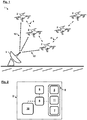
- Figure 1 shows a schematic perspective side view of a collaborative swarm 1 of mobile unmanned units 2 according to an embodiment of the invention.
- the mobile units are drones.
- a corresponding mobile unit 2 is shown schematically in detail in FIG Fig. 2 shown.
- it can be a small drone, a reconnaissance drone, an unmanned military reconnaissance aircraft and / or a combat drone or the like.
- the mobile units 2 form a collaborative, that is to say communicating and interacting, swarm 1, with the mobile units 2 assuming a certain movement formation at any point in time, in which each mobile unit 2 has a certain momentary position (as well as possibly speed and / or acceleration) is assigned in three-dimensional space.
- a swarm 1 of such mobile units 2 can be commanded and controlled for this purpose by a central and possibly ground-based system control device 3 via a corresponding wireless control network 12.
- a centralized approach can be disadvantageous when used in environments prone to interference or under highly dynamic conditions, for example in the event that a communication link to the control network 12 is temporary or is permanently disturbed or completely prevented.
- the present system provides a dedicated swarm network 4 via which the mobile units 2 can communicate with one another in a decentralized manner and exchange control commands, as will be explained below.
- each of the mobile units 2 comprises at least one communication unit 8 for data communication between the respective mobile unit 2 and the other mobile units 2 via the wireless swarm network 4.
- each mobile unit 2 comprises a position sensor system 9, which is used to determine a current absolute position P der respective mobile unit 2 is formed.
- the position sensor system 9 can contain an inertial navigation system 5, for example with an IMU. By integrating the accelerations and rotation rates measured by the IMU, the spatial movement of the mobile unit and from this the respective geographical position is continuously determined in the inertial navigation system 5. Measurement inaccuracies and noise on the sensors, however, inevitably lead to so-called drift errors in the navigation states such as speed, position, rotation rates and angle.
- drift means that a movement or rotation is detected even though the system is actually in a rest position.
- the corresponding errors add to the actual movement.
- drift errors increase over time and lead to the fact that the deviation from the actual position becomes more and more pronounced.
- the present system minimizes such and other measurement inaccuracies in that the movement formation of the mobile units 2 is optimally designed and dynamically, i.e. actively, adapted in accordance with the specific navigation and mission requirements, as will be explained below.
- the position sensor system 9 of the mobile units 2 is also designed to determine instantaneous relative positions of at least adjacent mobile units 2 with respect to the respective mobile unit 2 in the movement formation of the mobile units 2.
- the position sensor system 9 of the mobile units 2 is also designed to determine instantaneous relative positions of at least adjacent mobile units 2 with respect to the respective mobile unit 2 in the movement formation of the mobile units 2.
- the individual mobile units 2 only measure neighboring mobile units 2.
- the corresponding data can then be exchanged between these and the further mobile units 2 via the swarm network 4.
- each mobile unit 2 to measure the relative positions of all other mobile units 2.
- the position sensor system 9 is for this purpose equipped with a direction determination system 11, eg an optical and / or an infrared camera system with 360 ° viewing coverage, and an emission device 7 for emitting electromagnetic signals, eg light signals.
- the signals are detected with the directional determination system 11 of the respective mobile unit 2 to determine the relative position.
- the emission device 7 of each mobile unit 2 can pulse a specific coded light signal in different directions or send it out in a continuous wave, which makes the respective mobile unit 2 clearly identifiable with respect to the other units.
- direction vectors R of the respective mobile unit 2 to the neighboring mobile units 2 can be detected.
- the mobile units 2 can thus measure or estimate their own absolute position and the relative positions of the other units 2 via the position sensor system 9.
- the measurement of the absolute position is subject to the above-mentioned systematic inaccuracies. In a realistic application, the measured absolute position therefore does not correspond to the actual physical positions of the respective mobile unit 2 due to the drift errors and can thus be used to improve the estimation of the actual positions, which the present invention makes use of.
- the mobile units 2 are controlled and navigated by a central control device 10 on board, for which purpose the control device 10 on the mobile unit 2 with a flight guidance unit 6 and an in Fig. 2 drive, not shown, is coupled.
- the flight guidance unit 6 is in turn communicatively connected to the position sensor system 9 and the communication unit 8.
- Corresponding control signals are continuously exchanged with the other mobile units 2 via the swarm network 4.
- the swarm 1 can be used for completely different purposes, such as military operations including airborne air reconnaissance and air surveillance as well as tactical attack missions.
- a drone system can also be used for non-military Control and surveillance tasks, logistics and transport purposes, border surveillance, disaster control, research missions, etc. can be used.
- the collaborative drone swarm 1 can be used as a highly flexible radar system.
- each mobile unit 2 can furthermore carry a radar antenna unit for transmitting and receiving radar radiation.
- the components of a classic radar are distributed over a network of mobile units 2 in order to give the radar such a high degree of flexibility and robustness compared to conventional radar systems for tactical air reconnaissance or air surveillance.
- the system could thus replace and / or supplement corresponding conventional flying radar systems such as "Airborne Early Warning and Control Systems" (AWACS).
- AWACS Airborne Early Warning and Control Systems
- such a radar system can be used for battlefield reconnaissance or early detection of approaching missiles in the self-protection of ships, buildings, etc.
- the system can either be used actively as a classic radar function or passively to detect enemy signals.
- the radar properties can be adjusted at any time.
- certain geometries and arrangements are only possible because they are no longer limited by the design of the radar.
- flying platforms the system would no longer be ground-based and, in particular, could move freely vertically, whereby the advantages of flying radar systems (AWACs) such as battlefield reconnaissance or earlier detection of approaching missiles in the self-protection of ships are retained.
- AWACs flying radar systems
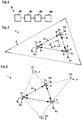
- control devices 10 of the mobile units 2 are for carrying out a method M according to FIG Fig. 3 designed, for which the mobile units 2 are in communication with the remaining mobile units 2 via the swarm network 4.
- the method M comprises under M1 taking a basic network structure 13 by the mobile units 2 within the movement formation.
- the basic network structure 13 defines a relative basic geometric arrangement in the positioning of the mobile units 2 within the movement formation. Examples of such a basic network structure 13 are given with reference to FIG Figures 4 to 8 discussed, the mobile units 2 in Figures 4 to 7 are positioned at the corner points of triangles. In Fig. 8 an example of an arrangement in a tetrahedron system is shown, which contains a total of 11 mobile units (in Fig. 8 nine of them are visible), which are arranged at the corner points of several interconnected tetrahedra.
- a triangle or tetrahedron here represents a particularly advantageous geometric basic structure for the constellation of the mobile units 2, since individual units can be added to the swarm 1 in a particularly simple manner, since only one additional tetrahedron has to be added per additional unit 2 (which newly added unit 2 forms a corner point of the new tetrahedron, while existing mobile units 2 represent the other corner points).
- the specifically chosen definition of the basic network structure 13 can be selected in accordance with the respective mission boundary conditions and optimized for the best navigation performance in each case.
- the basic network structure 13 can correspondingly represent a general network of (possibly regular) polygons and / or polyhedra, at whose corner points the mobile units 2 are positioned.
- a network or grid can now be set up from the mobile units 2, with each mobile unit 2 being assigned a corresponding position.
- the networking process can be implemented in different ways.
- a particularly simple networking variant is a sequential assignment to previously calculated positions, i.e. the mobile units 2 are commanded one after the other to the corresponding positions regardless of their current position.
- an edge or center-initiated network formation can alternatively be carried out, taking into account the current positions.
- the method M also includes, under M2, continuous mutual measurement M2 of the current relative positions of the mobile units 2 by the mobile units 2 and under M3, dynamic adaptation of M3 of the current relative positions by the mobile units 2 according to the basic network structure 13.
- the basic network structure 13, once adopted, thus becomes consistent actively controlled and adjusted accordingly. With such a predetermined position arrangement of the mobile units 2 and mutual measurements among one another, a higher navigation performance of the swarm 1 and of the individual participating units 2 can be achieved.
- a Optimization approach can be pursued, for example a gradient method or the like.
- a corresponding quality functional relevant to navigation can serve as the basis for this, the track of which can be calculated for determining the optimal arrangement.
- Additional parameters such as dilution-of-precision minimization (DOP) or observability maximization can be used to form the quality functional.
- DOP dilution-of-precision minimization
- observability maximization can be used to form the quality functional.
- further aspects of the formation of the movement formation can be optimized accordingly, e.g. the network formation (point or multi-point initiated, edge initiated, center initiated, etc.) as well as the volume / area specification of the constellation (overall geometry of the motion formation, packing density, edge specifications, distances).
- appropriate optimal solutions can be found on an iterative basis, for example by means of the LSQ method.
- the method M under M4 includes individual or joint swapping M4 of the positions of the mobile units 2 in the movement formation while maintaining the basic network structure 13 Measurement of the absolute positions of the mobile units 2 is used. This alternation of the positions can be continued continuously until a predetermined positional accuracy for the movement formation is achieved.
- this navigation-optimized constellation design is explained using simplified examples.
- the individual mobile units 2, while maintaining the basic network structure 13, can be commanded individually or in more or less large groups of the swarm 1 in such a way that the newly commanded positions and corresponding new measurements result in a better observation of the overall system and thus a minimization of residual errors.
- Fig. 4 shows a specific schematic view of a basic network structure 13 for the swarm 1 Fig. 1 including scaling errors.
- each mobile unit 2 provides a measurement / estimate of its absolute position P1-P3, which is, however, prone to errors (initial errors, drift, etc.). Furthermore, each mobile unit 2 provides measured relative positions in the form of direction vectors R to the other units 2. These direction vectors R are measured starting from the actual positions T1-T3 of the units 2, with an individual deviation between the absolute positions P1-P3 and the actual positions T1-T3 resulting (dashed lines in Fig. 4 ). Furthermore, the measurements of the relative positions are also subject to scaling errors. This is done in Fig.
- Fig. 5 shows the basic network structure 13 from Fig. 4 with possible changes in the position of the mobile units 2 in the course of method step M4 Fig. 3 .
- each of the mobile units 2 assumes a new position for improved observation, the positioning of the units 2 in each case being mirrored on the side edges of the triangle, ie the basic network structure 13.
- the basic network structure 13 is retained (dotted triangles in Fig. 5 ), but the movement formation of the mobile units 2, ie their absolute positioning and orientation in the area or in space, is mirrored. In a corresponding three-dimensional generalization of this example, the positions on faces of tetrahedra would be mirrored.
- the individual mobile units 2 can change their positions one after the other and / or at the same time.
- the position changes provide additional observations / direction measurements, by means of which possible scaling errors can be eliminated.
- Active constellation changes while maintaining the basic network structure 13 thus serve to improve the navigation solution. This is referring to Figures 6 and 7 made clear.
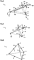
- FIGS. 5 show schematic views of the basic network structure 13 from FIG Fig. 5 after the position change of a mobile unit 2 from the actual position T2 to the actual position T2 '.
- a reflection is carried out on the opposite side of the triangle of the basic network structure 13 (solid arrows in Fig. 6 ).
- the positions have a scaling error, ie the mirroring is corresponding with a position shift the distance between the scaling error-prone position S2 to the position S2 'is carried out (reflection on the right side of the inner triangle in Fig. 6 ).
- the relative positions ie the direction vectors R, are then redetermined at the new actual positions T1, T2 'and T3.
- the positions now accepted can then be used as a starting solution for a new position determination. If this strategy is followed iteratively, the absolute positions can be determined on the basis of LSQ equation systems or filtering approaches of the mobile units 2 in such a way that the measurements are best fulfilled and the initial deviation of the displaced units 2 always decrease. There is thus a tendency towards convergence, as indicated by the correction tendencies E in indicated by arrows Fig. 7 is drawn. This means that the initial scaling error from the first position determination decreases and is largely eliminated in the sequential application to all units 2.
- Such an optimization process can be carried out continuously while the swarm 1 is in use. If the method is used as early as possible, residual errors in the navigation solutions can be kept small from the start. In principle, however, the method described can also be used for other types of position changes and different numbers of moving mobile units 2. For example, the actual movement formation can also remain unchanged when changing the positions. In a specific example, the mobile units 2 can be changed in pairs or permuted in larger groups. In other examples, the entire movement formation can also be rotated and / or mirrored. For example, the formation in Fig. 8 be rotated or mirrored in three-dimensional space, the basic basic network structure 13, ie the tetrahedron structure, not changing. In this case, too, new measurements can be carried out at the newly assumed positions, which can be used for a more precise definition of the positional accuracy.
- the process can be controlled centrally or decentrally.
- a centralized approach can, for example, provide that the measurements and state estimates of all mobile units 2 are processed at one point and the resulting results together with the associated control commands are then distributed.
- the control device 10 of a specific mobile unit 2 can function at least temporarily as such a central processing point. This task can be switched between the mobile units 2.
- a decentralized approach can provide that the available information is processed locally in all units 2 and then distributed further via the swarm network 4. Each unit 2 could thus independently calculate its own position and navigation updates. In principle, the determination of the absolute positions does not have to be implemented using strapdown propagation, but can also be implemented using other measurement approaches.
Landscapes
- Engineering & Computer Science (AREA)
- Aviation & Aerospace Engineering (AREA)
- Radar, Positioning & Navigation (AREA)
- Remote Sensing (AREA)
- Physics & Mathematics (AREA)
- General Physics & Mathematics (AREA)
- Automation & Control Theory (AREA)
- Control Of Position, Course, Altitude, Or Attitude Of Moving Bodies (AREA)
Applications Claiming Priority (1)
| Application Number | Priority Date | Filing Date | Title |
|---|---|---|---|
| DE102020000663.9A DE102020000663A1 (de) | 2020-01-31 | 2020-01-31 | Verfahren zur Verbesserung einer Navigationsgüte durch aktive Gestaltung einer Bewegungsformation eines kollaborierenden Schwarms aus mobilen unbemannten Einheiten |
Publications (1)
| Publication Number | Publication Date |
|---|---|
| EP3859481A1 true EP3859481A1 (fr) | 2021-08-04 |
Family
ID=73856073
Family Applications (1)
| Application Number | Title | Priority Date | Filing Date |
|---|---|---|---|
| EP20215907.5A Withdrawn EP3859481A1 (fr) | 2020-01-31 | 2020-12-21 | Procédé d'amélioration de la qualité de la navigation par conception active des informations de mouvement d'un groupe collaborant d'unités mobiles sans équipage |
Country Status (2)
| Country | Link |
|---|---|
| EP (1) | EP3859481A1 (fr) |
| DE (1) | DE102020000663A1 (fr) |
Cited By (3)
| Publication number | Priority date | Publication date | Assignee | Title |
|---|---|---|---|---|
| CN116086494A (zh) * | 2023-01-03 | 2023-05-09 | 南京航空航天大学 | 一种基于伪观测的异构飞行集群惯导误差协同修正方法 |
| US20240174383A1 (en) * | 2022-11-28 | 2024-05-30 | United Arab Emirates University | Satellite Array System for Detection and Identification |
| CN120704404A (zh) * | 2025-08-26 | 2025-09-26 | 成都时代星光科技有限公司 | 一种多无人机编队飞行系统实现方法、装置及介质 |
Families Citing this family (1)
| Publication number | Priority date | Publication date | Assignee | Title |
|---|---|---|---|---|
| DE102023136871B4 (de) * | 2023-12-29 | 2025-10-02 | Deutsches Zentrum für Luft- und Raumfahrt e.V. | Verfahren und System zum Steuern eines Schwarms aus Flugobjekten |
Citations (7)
| Publication number | Priority date | Publication date | Assignee | Title |
|---|---|---|---|---|
| US5521817A (en) * | 1994-08-08 | 1996-05-28 | Honeywell Inc. | Airborne drone formation control system |
| EP2184617A2 (fr) | 2008-11-06 | 2010-05-12 | Samsung Electronics Co., Ltd. | Procédé de localisation de position et système utilisant une localisation sécurisée de plan d'utilisateur |
| EP2749842A1 (fr) | 2009-04-22 | 2014-07-02 | Honeywell International Inc. | Procédé et système pour la navigation collaborative |
| US20160293018A1 (en) * | 2015-04-01 | 2016-10-06 | Korea University Research And Business Foundation | Method of controlling fleet of drones |
| EP2730887B1 (fr) | 2012-11-08 | 2017-02-22 | Honeywell International Inc. | Sélection d'état partagé et échange de données de navigation collaboratif utilisant des filtres parallèles indépendants de manière conditionnelle |
| US20180074520A1 (en) * | 2016-09-13 | 2018-03-15 | Arrowonics Technologies Ltd. | Formation flight path coordination of unmanned aerial vehicles |
| EP3454316A1 (fr) | 2017-09-08 | 2019-03-13 | Thales | Essaim constitue d'une pluralite de drones volants legers |
Family Cites Families (2)
| Publication number | Priority date | Publication date | Assignee | Title |
|---|---|---|---|---|
| JP2020531351A (ja) | 2017-08-15 | 2020-11-05 | オッテンハイマーズ インコーポレイテッド | 遠隔物体の捕捉 |
| US10909712B2 (en) | 2018-05-21 | 2021-02-02 | Microsoft Technology Licensing, Llc | Precision mapping using autonomous devices |
-
2020
- 2020-01-31 DE DE102020000663.9A patent/DE102020000663A1/de active Pending
- 2020-12-21 EP EP20215907.5A patent/EP3859481A1/fr not_active Withdrawn
Patent Citations (7)
| Publication number | Priority date | Publication date | Assignee | Title |
|---|---|---|---|---|
| US5521817A (en) * | 1994-08-08 | 1996-05-28 | Honeywell Inc. | Airborne drone formation control system |
| EP2184617A2 (fr) | 2008-11-06 | 2010-05-12 | Samsung Electronics Co., Ltd. | Procédé de localisation de position et système utilisant une localisation sécurisée de plan d'utilisateur |
| EP2749842A1 (fr) | 2009-04-22 | 2014-07-02 | Honeywell International Inc. | Procédé et système pour la navigation collaborative |
| EP2730887B1 (fr) | 2012-11-08 | 2017-02-22 | Honeywell International Inc. | Sélection d'état partagé et échange de données de navigation collaboratif utilisant des filtres parallèles indépendants de manière conditionnelle |
| US20160293018A1 (en) * | 2015-04-01 | 2016-10-06 | Korea University Research And Business Foundation | Method of controlling fleet of drones |
| US20180074520A1 (en) * | 2016-09-13 | 2018-03-15 | Arrowonics Technologies Ltd. | Formation flight path coordination of unmanned aerial vehicles |
| EP3454316A1 (fr) | 2017-09-08 | 2019-03-13 | Thales | Essaim constitue d'une pluralite de drones volants legers |
Cited By (4)
| Publication number | Priority date | Publication date | Assignee | Title |
|---|---|---|---|---|
| US20240174383A1 (en) * | 2022-11-28 | 2024-05-30 | United Arab Emirates University | Satellite Array System for Detection and Identification |
| US12312103B2 (en) * | 2022-11-28 | 2025-05-27 | United Arab Emirates University | Satellite array system for detection and identification |
| CN116086494A (zh) * | 2023-01-03 | 2023-05-09 | 南京航空航天大学 | 一种基于伪观测的异构飞行集群惯导误差协同修正方法 |
| CN120704404A (zh) * | 2025-08-26 | 2025-09-26 | 成都时代星光科技有限公司 | 一种多无人机编队飞行系统实现方法、装置及介质 |
Also Published As
| Publication number | Publication date |
|---|---|
| DE102020000663A1 (de) | 2021-08-05 |
Similar Documents
| Publication | Publication Date | Title |
|---|---|---|
| EP3859481A1 (fr) | Procédé d'amélioration de la qualité de la navigation par conception active des informations de mouvement d'un groupe collaborant d'unités mobiles sans équipage | |
| EP0276454B1 (fr) | Système de poursuite d'une cible | |
| DE69508783T2 (de) | Autopilot mit Lern- und Wiedergabemoden | |
| DE69501209T2 (de) | System zur regelung von ferngesteuerten fahrzeugen mit variablen bezugsrahmen | |
| DE102005038017B3 (de) | Verfahren zur Flugführung mehrerer im Verband fliegender Flugzeuge | |
| DE1936820C1 (de) | Zielverfolgungsgerät für Luftfahrzeuge | |
| DE102008050951A1 (de) | Rechnerzeitoptimierte Routenplanung für Luftfahrzeuge | |
| DE102020203054B4 (de) | Verfahren zur Steuerung einer Formation eines zusammenwirkenden Schwarms von unbemannten mobilen Einheiten | |
| DE2802492A1 (de) | Zielverfolgungssystem | |
| DE102019007833A1 (de) | Radarsystem | |
| AT516789A1 (de) | Verfahren zum Fernsteuern eines Fahrzeugs | |
| DE102019000958A1 (de) | Drohnenverbund und Markierverfahren für eine markergelenkte Maßnahme | |
| EP3620819B1 (fr) | Détection coordonnée des objets dans un espace aérien | |
| DE10341893B4 (de) | Verfahren zur Verringerung des Dopplerzentroids bei einem kohärenten impuls-Radarsystem sowie Verwendung des Verfahrens | |
| EP4256415A1 (fr) | Procédé de commande d'un drone le long d'un puits | |
| EP3584600B1 (fr) | Recherche coordonnée d'un espace aérien | |
| EP0207521B1 (fr) | Système de mesure de cible | |
| DE102016110477B4 (de) | Verfahren zum Positionieren eines insbesondere unbemannten Luftfahrzeuges mit Hilfe einer aktiven statischen Bodenstation sowie Luftfahrzeug und Bodenstation zur Durchführung des Verfahrens | |
| DE102023136871B4 (de) | Verfahren und System zum Steuern eines Schwarms aus Flugobjekten | |
| EP2395409B1 (fr) | Procédé et dispositif destinés à la commande d'un missile guidé | |
| DE2445478C3 (de) | Verfahren zur autonomen Zielselektion | |
| DE2827056C2 (de) | Flugkörperlenksystem | |
| DE3642767B3 (de) | Winkelverfolgungsradarsystem | |
| DE102023118284B4 (de) | Verfahren zum Steuern eines Schwarms aus Flugobjekten und System hierzu | |
| DE102007056661A1 (de) | Unbemannter Flugkörper |
Legal Events
| Date | Code | Title | Description |
|---|---|---|---|
| PUAI | Public reference made under article 153(3) epc to a published international application that has entered the european phase |
Free format text: ORIGINAL CODE: 0009012 |
|
| STAA | Information on the status of an ep patent application or granted ep patent |
Free format text: STATUS: THE APPLICATION HAS BEEN PUBLISHED |
|
| AK | Designated contracting states |
Kind code of ref document: A1 Designated state(s): AL AT BE BG CH CY CZ DE DK EE ES FI FR GB GR HR HU IE IS IT LI LT LU LV MC MK MT NL NO PL PT RO RS SE SI SK SM TR |
|
| STAA | Information on the status of an ep patent application or granted ep patent |
Free format text: STATUS: THE APPLICATION IS DEEMED TO BE WITHDRAWN |
|
| 18D | Application deemed to be withdrawn |
Effective date: 20220205 |