EP3859593A1 - Procédé et dispositif d'acquisition de caractéristiques de véhicule - Google Patents
Procédé et dispositif d'acquisition de caractéristiques de véhicule Download PDFInfo
- Publication number
- EP3859593A1 EP3859593A1 EP19864666.3A EP19864666A EP3859593A1 EP 3859593 A1 EP3859593 A1 EP 3859593A1 EP 19864666 A EP19864666 A EP 19864666A EP 3859593 A1 EP3859593 A1 EP 3859593A1
- Authority
- EP
- European Patent Office
- Prior art keywords
- vehicle
- region
- processed image
- feature
- image
- Prior art date
- Legal status (The legal status is an assumption and is not a legal conclusion. Google has not performed a legal analysis and makes no representation as to the accuracy of the status listed.)
- Granted
Links
Images


Classifications
-
- G—PHYSICS
- G06—COMPUTING OR CALCULATING; COUNTING
- G06V—IMAGE OR VIDEO RECOGNITION OR UNDERSTANDING
- G06V20/00—Scenes; Scene-specific elements
- G06V20/50—Context or environment of the image
- G06V20/56—Context or environment of the image exterior to a vehicle by using sensors mounted on the vehicle
- G06V20/58—Recognition of moving objects or obstacles, e.g. vehicles or pedestrians; Recognition of traffic objects, e.g. traffic signs, traffic lights or roads
-
- G—PHYSICS
- G06—COMPUTING OR CALCULATING; COUNTING
- G06T—IMAGE DATA PROCESSING OR GENERATION, IN GENERAL
- G06T7/00—Image analysis
- G06T7/70—Determining position or orientation of objects or cameras
- G06T7/73—Determining position or orientation of objects or cameras using feature-based methods
-
- G—PHYSICS
- G06—COMPUTING OR CALCULATING; COUNTING
- G06V—IMAGE OR VIDEO RECOGNITION OR UNDERSTANDING
- G06V10/00—Arrangements for image or video recognition or understanding
- G06V10/70—Arrangements for image or video recognition or understanding using pattern recognition or machine learning
- G06V10/764—Arrangements for image or video recognition or understanding using pattern recognition or machine learning using classification, e.g. of video objects
-
- G—PHYSICS
- G06—COMPUTING OR CALCULATING; COUNTING
- G06T—IMAGE DATA PROCESSING OR GENERATION, IN GENERAL
- G06T2207/00—Indexing scheme for image analysis or image enhancement
- G06T2207/30—Subject of image; Context of image processing
- G06T2207/30248—Vehicle exterior or interior
- G06T2207/30252—Vehicle exterior; Vicinity of vehicle
-
- G—PHYSICS
- G06—COMPUTING OR CALCULATING; COUNTING
- G06V—IMAGE OR VIDEO RECOGNITION OR UNDERSTANDING
- G06V10/00—Arrangements for image or video recognition or understanding
- G06V10/40—Extraction of image or video features
- G06V10/42—Global feature extraction by analysis of the whole pattern, e.g. using frequency domain transformations or autocorrelation
- G06V10/422—Global feature extraction by analysis of the whole pattern, e.g. using frequency domain transformations or autocorrelation for representing the structure of the pattern or shape of an object therefor
-
- G—PHYSICS
- G06—COMPUTING OR CALCULATING; COUNTING
- G06V—IMAGE OR VIDEO RECOGNITION OR UNDERSTANDING
- G06V10/00—Arrangements for image or video recognition or understanding
- G06V10/70—Arrangements for image or video recognition or understanding using pattern recognition or machine learning
- G06V10/82—Arrangements for image or video recognition or understanding using pattern recognition or machine learning using neural networks
-
- G—PHYSICS
- G06—COMPUTING OR CALCULATING; COUNTING
- G06V—IMAGE OR VIDEO RECOGNITION OR UNDERSTANDING
- G06V20/00—Scenes; Scene-specific elements
- G06V20/50—Context or environment of the image
- G06V20/56—Context or environment of the image exterior to a vehicle by using sensors mounted on the vehicle
- G06V20/58—Recognition of moving objects or obstacles, e.g. vehicles or pedestrians; Recognition of traffic objects, e.g. traffic signs, traffic lights or roads
- G06V20/584—Recognition of moving objects or obstacles, e.g. vehicles or pedestrians; Recognition of traffic objects, e.g. traffic signs, traffic lights or roads of vehicle lights or traffic lights
-
- G—PHYSICS
- G06—COMPUTING OR CALCULATING; COUNTING
- G06V—IMAGE OR VIDEO RECOGNITION OR UNDERSTANDING
- G06V2201/00—Indexing scheme relating to image or video recognition or understanding
- G06V2201/08—Detecting or categorising vehicles
Definitions
- the present disclosure relates to the field of vehicle, and in particular to a method and a device for acquiring a vehicle feature.
- a target image may be analyzed to obtain a target object in the target image, and a feature of the target object may be acquired for subsequent analysis.
- the condition of a road may be determined based on the color, shape, size, location and other feathers of a target object on the road that are acquired by recognizing the target object in a target image of the road.
- the target object may be, for example, a vehicle, a building, or a pedestrian.
- the target object in the target image is presented as a plane region.
- the vehicle and the pedestrian in the target image may be presented as respective regions in rectangular frames.
- the size of a region may depend on the size of the target object and a shooing parameter of the target image.
- the color of pixels in the region may depend on the color of the target object.
- a method and a device for acquiring a vehicle feature are provided according to embodiments of the present disclosure, by which regions in the vehicle in the to-be-processed image are obtained, and then region features are acquired from the obtained regions, so that a more comprehensive vehicle feature can be obtained.
- the method for acquiring a vehicle feature includes: acquiring a to-be-processed image including a vehicle; recognizing a feature element of the vehicle from the to-be-processed image, the feature element including a side element and an element of a vehicle end, and the vehicle end including a head of the vehicle or a rear of the vehicle; determining a side region of the vehicle and an end region of the vehicle, based on a position of the side element in the to-be-processed image and a position of the element of the vehicle end in the to-be-processed image; and acquiring a side region feature based on the side region, and an end region feature based on the end region.
- the determining a side region of the vehicle and an end region of the vehicle, based on a position of the side element in the to-be-processed image and a position of the element of the vehicle end in the to-be-processed image includes: determining, in the to-be-processed image, a vehicle region where the vehicle locates; determining a boundary between the side region and the end region, based on the position of the element that is of the vehicle end and is close to the side element in the to-be-processed image and the position of the side element that is close to the element of the vehicle end in the to-be-processed image; and determining, in the vehicle region, the side region and the end region, based on the boundary, the position of the side element in the to-be-processed image, and the position of the element of the vehicle end in the to-be-processed image.
- the method further includes: determining a relative position of the vehicle to an image capturing device, based on the end region feature, the side region feature and a shooting parameter of the to-be-processed image, the image capturing device being a device that photographs the vehicle to obtain the to-be-processed image.
- the determining a relative position of the vehicle to an image capturing device, based on the end region feature, the side region feature and the shooting parameter of the to-be-processed image includes: determining, one of the end region and the side region, that faces toward the image capturing device as a target region; and determining the relative position of the vehicle to the image capturing device, based on a region feature of the target region and the shooting parameter of the to-be-processed image.
- the determining a relative position of the vehicle to an image capturing device, based on the end region feature, the side region feature and a shooting parameter of the to-be-processed image includes: determining the relative position of the vehicle to the image capturing device, based on a boundary between the end region and the side region, and the shooting parameter of the to-be-processed image.
- the side region feature includes a position of a vertex of the side region in the to-be-processed image, a position of a center point of the side region in the to-be-processed image, or a position of a midpoint of an edge of the side region in the to-be-processed image; and the end region feature includes a position of a vertex of the end region in the to-be-processed image, a position of a center point of the end region in the to-be-processed image, or a position of a midpoint of an edge of the end region in the to-be-processed image.
- the recognizing a feature element of the vehicle from the to-be-processed image includes: recognizing the vehicle region where the vehicle locates in the to-be-processed image; clipping the vehicle region from the to-be-processed image to generate a vehicle image; and recognizing the feature element of the vehicle from the vehicle image.
- the element of the head of the vehicle includes one or more of a front light, a front window, a bumper and a front license plate
- the element of the rear of the vehicle includes one or more of a rear light, a rear window, and a rear license plate
- the side element includes one or more of a wheel, a side window, a rearview mirror, and a door.
- the device for acquiring a vehicle feature includes: an image acquisition unit configured to acquire a to-be-processed image including a vehicle; an image recognition unit configured to recognize a feature element of the vehicle from the to-be-processed image, the feature element including a side element and an element of a vehicle end, and the vehicle-end including a head of the vehicle or a rear of the vehicle; a region determination unit, configured to determine a side region of the vehicle and an end region of the vehicle, based on a position of the side element in the to-be-processed image and a position of the element of the vehicle end in the to-be-processed image; and a feature acquisition unit configured to acquire a side region feature based on the side region, and acquire an end region feature based on the end region.
- the region determination unit includes: a vehicle region determination unit configured to determine, in the to-be-processed image, a vehicle region where the vehicle locates; a boundary determination unit configured to determine a boundary between the side region and the end region, based on the position of the element that is of the vehicle end and is close to the side element in the to-be-processed image and the position of the side element that is close to the element of the vehicle end in the to-be-processed image; and a region determination subunit configured to determine, in the vehicle region, the side region and the end region, based on the boundary, the position of the side element in the to-be-processed image, and the position of the element of the vehicle end in the to-be-processed image.
- the device further includes: a relative position determination unit, configured to determine a relative position of the vehicle to an image capturing device, based on the end region feature, the side region feature and the shooting parameter of the to-be-processed image, the image capturing device being a device that photographs the vehicle to obtain the to-be-processed image.
- a relative position determination unit configured to determine a relative position of the vehicle to an image capturing device, based on the end region feature, the side region feature and the shooting parameter of the to-be-processed image
- the image capturing device being a device that photographs the vehicle to obtain the to-be-processed image.
- the relative position determination unit includes: a target region determination unit configured to determine, one of the end region and the side region, that faces toward the image capturing device as a target region; and a relative position determination subunit configured to determine the relative position of the vehicle to the image capturing device, based on a region feature of the target region and the shooting parameter of the to-be-processed image.
- the relative position determination unit is configured to determine the relative position of the vehicle to the image capturing device, based on a boundary between the end region and the side region, and the shooting parameter of the to-be-processed image.
- the side region feature includes a position of a vertex of the side region in the to-be-processed image, a position of a center point of the side region in the to-be-processed image, or a position of a midpoint of an edge of the side region in the to-be-processed image; and the end region feature includes a position of a vertex of the end region in the to-be-processed image, a position of a center point of the end region in the to-be-processed image, or a position of a midpoint of an edge of the end region in the to-be-processed image.
- the image recognition unit includes: a vehicle region recognition unit configured to recognize the vehicle region where the vehicle locates in the to-be-processed image; a vehicle image acquisition unit configured to clip the vehicle region from the to-be-processed image to generate a vehicle image; and a feature element recognition unit configured to recognize the feature element of the vehicle from the vehicle image.
- the element of the head of the vehicle includes one or more of a front light, a front window, a bumper and a front license plate
- the element of the rear of the vehicle includes one or more of a rear light, a rear window, and a rear license plate
- the side element includes one or more of a wheel, a side window, a rearview mirror, and a door.
- a to-be-processed image including a vehicle is acquired.
- a feature element of the vehicle is then recognized from the to-be-processed image, where the feature element may be a side element and an element of a vehicle end, and the vehicle-end may be a head of the vehicle or a rear of the vehicle.
- a side region of the vehicle and an end region of the vehicle may be determined.
- a side region feature may be acquired based on the side region
- an end region feature may be acquired based on the end region.
- regions in the vehicle in the to-be-processed image are first obtained, and then region features are acquired from the obtained regions, which can obtain a more comprehensive vehicle feature, compared with the conventional technology of determining only a position of the vehicle in the to-be-processed image.
- a target image may be analyzed to obtain a target object in the target image, and a feature of the target object may be acquired for subsequent analysis.
- the condition of a road may be determined based on the color, shape, size, location and other feathers of a target object on the road that are acquired by recognizing the target object in a target image of the road.
- the target object may be, for example, a vehicle, a building, or a pedestrian.
- the target object in the target image is presented as a plane region.
- Figure 1 is a schematic diagram of acquiring a feature from a target image according to the conventional technology.
- the vehicle and the pedestrian in the target image are presented as respective regions in rectangular frames with different colors.
- the size of the vehicle region depends on the size of the vehicle and a shooing parameter for the vehicle.
- the color of pixels in the vehicle region depends on the color of the vehicle.
- the vehicle has three-dimensional features, such as posture of the vehicle and a distance to an image capturing device, and the plane region may fail to reflect the three-dimensional features.
- Figure 1 is a schematic diagram of acquiring a feature through a target image according to the conventional technology.
- the left rear of the vehicle presented in the lower left corner is closer to the image capturing device.
- the calculated distance shall indicate the distance between the interior of the vehicle and the image capturing device. Therefore, the calculated distance is greater than the actual distance from the vehicle to the image capturing device.
- Such calculated result may lead to serious consequences if being used in a driving assistance system.
- a to-be-processed image including a vehicle may be acquired.
- a feature element of the vehicle is then recognized from the to-be-processed image, where the feature element may include a side element and an element of a vehicle end, and the vehicle end may be a head of the vehicle or a rear of the vehicle.
- a side region of the vehicle and an end region of the vehicle may be determined.
- a side region feature may be acquired based on the side region
- an end region feature may be acquired based on the end region.
- regions in the vehicle in the to-be-processed image are first obtained, and then region features are acquired from the obtained regions, which can obtain a more comprehensive vehicle feature, compared with the conventional technology of determining only a position of the vehicle in the to-be-processed image.
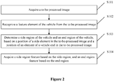
- FIG. 2 is a flow chart of a method for acquiring a vehicle feature according to an embodiment of the present disclosure.
- the method includes steps S101 to S 104 as follows.
- step S101 a to-be-processed image is acquired.
- a target image is used as the to-be-processed image.
- the to-be-processed image includes a vehicle and may be captured by an image capturing device such as a camera, a camcorder and the like.
- the to-be-processed image may include only the vehicle, or may further include a target object other than the vehicle.
- the to-be-processed image may include one or multiple vehicles.
- step S102 a feature element of the vehicle is recognized from the to-be-processed image.
- the feature element of the vehicle may include a side element and an element of a vehicle end.
- the vehicle end may be a head of the vehicle or a rear of the vehicle.
- the element of the head of the vehicle may include, for example, one or more of a front light, a front window, a bumper, a front license plate and any other element that may assist recognizing a position of the head of the vehicle.
- the element of the rear of the vehicle may include, for example, one or more of a rear light, a rear window, a rear license plate and any other element that may assist recognizing a position of the rear of the vehicle.
- the side element may include, for example, one or more of a wheel, a side window, a rearview mirror, a door and any other element that may assist recognizing a position of the side of the vehicle.
- the recognizing a feature element of the vehicle from the to-be-processed image may include dividing the to-be-processed image to obtain category labels of pixels in the to-be-processed image.
- the category labels of the pixels of a same feature element are the same. Therefore, the feature element of the vehicle is obtained based on the category labels.
- the division of the to-be-processed image may be realized by means of a pre-trained neutral network for deep learning. Specifically, a red elliptical region may be recognized as a light region, a large gray rectangular region may be recognized as a window region, and a circular region with white rays may be recognized as a wheel region, and so on.
- the divided image may be generated having different colors preset for different category labels, in order to facilitate process on the divided image.
- the category label of the light region may correspond to a color of red
- the category label of the window region may correspond to a color of blue, and the like.
- the recognizing a feature element from the to-be-processed image may include: recognizing and clipping, from the to-be-processed image, a vehicle region where the vehicle locates, to generate a target image; and recognizing the feature element in the vehicle region from the target image.
- a first divided image may be obtained by performing recognition on the to-be-processed image using a pre-trained first neutral network for deep learning. Pixels in the first divided image have respective category labels, and the category labels of the pixels of a same target object are the same. Therefore, the vehicle region in the to-be-processed image may be recognized based on the category labels.
- a second divided image may be obtained by performing recognition on the target image using a pre-trained second neural network for deep learning. Pixels in the second divided image have respective category labels, and the category labels relating to a same feature element are the same. Therefore, the feature element in the vehicle region may be recognized based on the category labels.
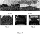
- Figure 3 is a schematic diagram of a process of recognizing a feature element according to an embodiment of the present disclosure.
- Figure 3(a) is an exemplary to-be-processed image, which is divided through a first neutral network for deep learning to obtain a first divided image as shown in Figure 3(b) .
- the region within the rectangular frame indicates a vehicle region where the vehicle locates.
- a vehicle division image is obtained as shown in Figure 3(c) .
- a vehicle image is obtained as shown in Figure 3(d) .
- a second divided image is obtained as shown in Figure 3(e) , in which the two circular regions indicate lights on the vehicle, and the rectangular region indicates a window on the vehicle.
- Figure 3(e) a second divided image is obtained as shown in Figure 3(e) , in which the two circular regions indicate lights on the vehicle, and the rectangular region indicates a window on the vehicle.
- a wheel, a rearview mirror and any other element may be recognized in the embodiment of the present disclosure.
- step S103 a side region of the vehicle and an end region of the vehicle are determined based on the side element and the element of the vehicle end.
- the vehicle in the to-be-processed image includes at least a side element and an element of a vehicle end.
- a side region of the vehicle and an end region may be determined directly based on the side element and the element of the vehicle end.
- the element of the rear of the vehicle includes a rear light, a window and the like
- the side element includes a wheel, a rearview mirror and the like. It may be determined that the wheel included in the side element is a rear wheel, thereby determining that the region of the rear of the vehicle in the to-be-processed image includes the rectangular region where the vehicle locates and the side region includes the left edge and the right edge of the region of the rear of the vehicle.
- a vehicle region where the vehicle locates and a boundary between the side region and the end region may be determined. Then the side region and the end region may be determined in the vehicle region based on the boundary.
- the boundary between the side region and the end region may be determined based on a position of the element that is of the vehicle end and is close to the side element in the to-be-processed image and a position of the side element that is close to the element of the vehicle end in the to-be-processed image.
- Figure 4 is a schematic diagram of a process of determining a region according to an embodiment of the present disclosure.
- a to-be-processed image shown in Figure 4(a) may be divided to obtain a vehicle region (the gray rectangular frame) shown in Figure 4(b).
- Figure 4(c) shows feature elements obtained by dividing the to-be-processed image, in which the two elliptical regions on the right (denoted by black lines) indicate lights on the vehicle, the quadrilateral region on the right (denoted by black lines) indicate a front window on the vehicle, the two elliptical regions on the left (denoted by white thin lines) indicate wheels of the vehicle, and the irregular shaped region (denoted by a white thin line) indicates a side window on the vehicle.
- the boundary between the head region and the side region may be determined based on following elements in the to-be-processed image: the right wheel, the right edge of the side window, the left edge of the front window, and the left front light on the vehicle.
- the boundary between the head region and the side region may be determined through various methods.
- the boundary may be determined based on the left edge of the front window and the right edge of the side window, or based on the right edge of the right wheel and the left edge of the left light.
- the boundary may be a vertical line or an oblique line.
- a vertical straight line at the right edge of the right wheel may be determined as the boundary between the head region and the side region, as shown by the gray line in Figure 4(d) .
- the side region and the end region may be determined in the vehicle region based on the determined boundary, the position of the side element in the to-be-processed image and the position of the element of the vehicle end in the to-be-processed image. It is to be understood that the side region and the end region are located respectively on two sides of the boundary.
- the side region or the end region may be a rectangular region, a parallelogram region, or a region in other shape.
- the side region and the end region may be determined in the vehicle region through various methods. For example, taking the vertical straight line at the right edge of the right wheel as the boundary between the head region and the side region, as shown in Figure 4(e) , a horizontal line passing through the contact points between the wheels and the ground may be determined as a lower edge of the head region, the boundary may be determined as a left edge of the head region, a horizontal line passing through the top of the vehicle may be determined as an upper edge of the head region, and the right edge of the vehicle region may be determined as a right edge of the head region. Therefore, the four edges forms the head region (the rectangle frame denoted by white bold lines on the right).
- the side region may be defined by four edges as follows (the parallelogram frame denoted by white bold lines on the left).
- the boundary may be determined as a right edge of the side region.
- the left edge of the vehicle region may be determined as a left edge of the side region.
- the direction of a line connecting the two contact points between wheels and the ground may be determined as the direction of an upper edge and a lower edge of the side region, where the right end of the upper edge coincides with the upper left vertex of the head region (that is, the intersection point of the horizontal line passing through the top of the vehicle and the boundary), and the right end of the lower edge coincides with the lower left vertex of the head region (that is, the contact point between the wheel and the ground).
- the side region and the end region may be represented by coordinates of six vertices in the to-be-processed image. Since the side region and the end region may be determined through various methods, as the boundary may be determined through various methods, multiple sets of the vertex coordinate values may be obtained. A weighted average of the multiple sets of vertex coordinate values may be obtained so as to indicate the side region and the end region with improved accuracy.
- step S104 a side region feature is acquired based on the side region, and an end region feature is acquired based on the end region.
- the side region feature may include a position of a vertex of the side region, a center point of the side region, a midpoint of an edge of the side region or another feature point of the side region in the to-be-processed image.
- the end region feature may include a position of a vertex of the end region, a center point of the end region, a midpoint of an edge of the end region or another feature point of the end region in the to-be-processed image.
- the head region feature may include a position of a vertex of the head region in the to-be-processed image, a position of a center point of the head region in the to-be-processed image, a position of a midpoint of an edge of the head region in the to-be-processed image, or a position of another feature point of the head region in the to-be-processed image.
- the position of the feature point in the to-be-processed image may be represented by a coordinate of the feature point in the to-be-processed image.
- a three-dimensional feature region of the vehicle may be obtained based on the vertices of both the side region and the end region.
- the three-dimensional feature region of the vehicle may include the head region, the rear region, the side regions at both sides, an upper region, and a lower region.
- a to-be-processed image including a vehicle is acquired.
- a feature element of the vehicle is then recognized from the to-be-processed image, where the feature element may include a side element and an element of a vehicle end, and the vehicle end may be a head of the vehicle or a rear of the vehicle.
- a side region of the vehicle and an end region of the vehicle may be determined.
- a side region feature may be acquired based on the side region
- an end region feature may be acquired based on the end region.
- regions in the vehicle in the to-be-processed image are first obtained, and then region features are acquired from the obtained regions, which can obtain a more comprehensive vehicle feature, compared with the conventional technology of determining only a position of the vehicle in the to-be-processed image.
- a vehicle feature is acquired for analysis, to obtain a result.
- a relative position of the vehicle to the image capturing device may be determined based on the end region feature, the side region feature and a shooting parameter of the to-be-processed image.
- the image capturing device is a device that photographs the vehicle to obtain the to-be-processed image.
- the shooting parameter of the to-be-processed image includes the focal length, the wide angle, the position, the rotation angle and/or other parameters that are used when the image capturing device photographs the vehicle.
- the relative position of a feature point to the image capturing device may be determined based on the position of the feature point in the to-be-processed image and the shooting parameter of the to-be-processed image.
- the end region feature and the side region feature in the to-be-processed image can comprehensively reflect a three-dimensional feature of the vehicle, which can be used to determine the relative position of the vehicle to the image capturing device.
- the determining a relative position of the vehicle to the image capturing device, based on the end region feature, the side region feature and a shooting parameter of the to-be-processed image may include: determining, one of the end region and the side region, that faces toward the image capturing device as a target region; and determining the relative position of the vehicle to the image capturing device, based on a region feature of the target region and the shooting parameter of the to-be-processed image.
- the target region that faces toward the image capturing device may be determined based on the size and/or shape of the end region and the side region. For example, a region with a relatively large size or a region in a rectangular shape may be determined as the target region that faces toward the image capturing device.
- the head region is larger than the side region, and then it may be determined that the head region faces toward the image capturing device. Therefore, the head region may be determined as the target region. Furthermore, the head region is in a rectangular shape while the side region is in a parallelogram region, and thus the head region may be determined as facing toward the image capturing device. Therefore, the head region may be determined as the target region.
- the region feature of the target region may include a position of a vertex of the target region in the to-be-processed image, a position of a center point of the target region in the to-be-processed image, a position of a midpoint of an edge of the target region in the to-be-processed image, or a position of any other feature point of the target region in the to-be-processed image.
- the target region is the head region
- a relative position of the center point of the head region to the image capturing device may be determined based on the position of the center point of the head region in the to-be-processed image and a shooting parameter of the to-be-processed image.
- the determining a relative position of the vehicle to the image capturing device, based on the end region feature, the side region feature and a shooting parameter of the to-be-processed image may include: determining the relative position of the vehicle to the image capturing device based on a boundary between the end region and the side region, and the shooting parameter of the to-be-processed image.
- a midpoint of the boundary may be determined, and the relative position of the vehicle to the image capturing device may be determined based on the midpoint of the boundary and the shooting parameter of the to-be-processed image. This is because the boundary between the end region and the side region is often the closest to the image capturing device, which may lead to a relatively accurate relative position of the vehicle to the image capturing device.
- a device for acquiring a vehicle feature is provided according to an embodiment of the present disclosure.
- Reference is made to Figure 5 which is a structural block diagram of a device for acquiring a vehicle feature according to an embodiment of the present disclosure.
- the device may include an image acquisition unit 110, an image recognition unit 120, a region determination unit 130 and a feature acquisition unit 140.
- the image acquisition unit 110 is configured to acquire a to-be-processed image including a vehicle.
- the image recognition unit 120 is configured to recognize a feature element of the vehicle from the to-be-processed image.
- the feature element includes a side element and an element of a vehicle end, and the vehicle end includes a head of the vehicle or a rear of the vehicle.
- the region determination unit 130 is configured to determine a side region of the vehicle and an end region of the vehicle, based on a position of the side element in the to-be-processed image and a position of the element of the vehicle end in the to-be-processed image.
- the feature acquisition unit 140 is configured to acquire a side region feature based on the side region, and acquire an end region feature based on the end region.
- the region determination unit includes a vehicle region determination unit, a boundary determination unit and a region determination subunit.
- the vehicle region determination unit is configured to determine, in the to-be-processed image, a vehicle region where the vehicle locates.
- the boundary determination unit is configured to determine a boundary between the side region and the end region, based on the position of the element that is of the vehicle end and is close to the side element in the to-be-processed image and the position of the side element that is close to the element of the vehicle end in the to-be-processed image.
- the region determination subunit is configured to determine, in the vehicle region, the side region and the end region, based on the boundary, the position of the side element in the to-be-processed image, and the position of the element of the vehicle end in the to-be-processed image.
- the device further includes a relative position determination unit, configured to determine the relative position of the vehicle to an image capturing device, based on the end region feature, the side region feature and the shooting parameter of the to-be-processed image.
- a relative position determination unit configured to determine the relative position of the vehicle to an image capturing device, based on the end region feature, the side region feature and the shooting parameter of the to-be-processed image.
- the relative position determination unit includes a target region determination unit and a relative position determination subunit.
- the target region determination unit is configured to determine one of the end region and the side region, that faces toward the image capturing device, as a target region.
- the image capturing device is a device that photographs the vehicle to obtain the to-be-processed image.
- the relative position determination subunit is configured to determine the relative position of the vehicle to the image capturing device, based on a region feature of the target region and the shooting parameter of the to-be-processed image.
- the relative position determination unit is configured to determine the relative position of the vehicle to the image capturing device, based on a boundary between the end region and the side region, and the shooting parameter of the to-be-processed image.
- the side region feature includes a position of a vertex of the side region in the to-be-processed image, a position of a center point of the side region in the to-be-processed image, or a position of a midpoint of an edge of the side region in the to-be-processed image; and the end region feature includes a position of a vertex of the end region in the to-be-processed image, a position of a center point of the end region in the to-be-processed image, or a position of a midpoint of an edge of the end region in the to-be-processed image.
- the image recognition unit includes a vehicle region recognition unit, a vehicle image acquisition unit and a feature element recognition unit.
- the vehicle region recognition unit is configured to recognize the vehicle region where the vehicle locates from the to-be-processed image.
- the vehicle image acquisition unit is configured to clip the vehicle region from the to-be-processed image to generate a vehicle image.
- the feature element recognition unit is configured to recognize a feature element of the vehicle from the vehicle image.
- the element of the head of the vehicle includes one or more of a front light, a front window, a bumper and a front license plate
- the element of the rear of the vehicle includes one or more of a rear light, a rear window, and a rear license plate
- the side element includes one or more of a wheel, a side window, a rearview mirror, and a door.
- a to-be-processed image including a vehicle is acquired.
- a feature element of the vehicle is then recognized from the to-be-processed image, where the feature element may include a side element and an element of a vehicle end, and the vehicle end may be a head of the vehicle or a rear of the vehicle.
- a side region of the vehicle and an end region of the vehicle may be determined.
- a side region feature may be acquired based on the side region
- an end region feature may be acquired based on the end region.
- regions in the vehicle in the to-be-processed image are first obtained, and then region features are acquired from the obtained regions, which can obtain a more comprehensive vehicle feature, compared with the conventional technology of determining only a position of the vehicle in the to-be-processed image.
- the computer software product may be stored in a storage medium, such as a read-only memory (ROM)/RAM, a magnetic disc, or an optical disk, and the computer software product includes multiple instructions for enabling a computer device (which may be a personal computer, a server, or a network communication device such as a router) to perform the methods described in various embodiments or some parts of the embodiments of the present disclosure.
- a computer device which may be a personal computer, a server, or a network communication device such as a router
Landscapes
- Engineering & Computer Science (AREA)
- Theoretical Computer Science (AREA)
- General Physics & Mathematics (AREA)
- Physics & Mathematics (AREA)
- Multimedia (AREA)
- Computer Vision & Pattern Recognition (AREA)
- Computing Systems (AREA)
- Artificial Intelligence (AREA)
- Health & Medical Sciences (AREA)
- Databases & Information Systems (AREA)
- Evolutionary Computation (AREA)
- General Health & Medical Sciences (AREA)
- Medical Informatics (AREA)
- Software Systems (AREA)
- Image Analysis (AREA)
- Image Processing (AREA)
Applications Claiming Priority (2)
| Application Number | Priority Date | Filing Date | Title |
|---|---|---|---|
| CN201811132325.XA CN109389064B (zh) | 2018-09-27 | 2018-09-27 | 一种车辆特征获取方法及装置 |
| PCT/CN2019/084537 WO2020062856A1 (fr) | 2018-09-27 | 2019-04-26 | Procédé et dispositif d'acquisition de caractéristiques de véhicule |
Publications (3)
| Publication Number | Publication Date |
|---|---|
| EP3859593A1 true EP3859593A1 (fr) | 2021-08-04 |
| EP3859593A4 EP3859593A4 (fr) | 2022-06-29 |
| EP3859593B1 EP3859593B1 (fr) | 2025-02-26 |
Family
ID=65418211
Family Applications (1)
| Application Number | Title | Priority Date | Filing Date |
|---|---|---|---|
| EP19864666.3A Active EP3859593B1 (fr) | 2018-09-27 | 2019-04-26 | Procédé et dispositif d'acquisition de caractéristiques de véhicule |
Country Status (5)
| Country | Link |
|---|---|
| US (1) | US12002269B2 (fr) |
| EP (1) | EP3859593B1 (fr) |
| JP (1) | JP7190583B2 (fr) |
| CN (1) | CN109389064B (fr) |
| WO (1) | WO2020062856A1 (fr) |
Families Citing this family (14)
| Publication number | Priority date | Publication date | Assignee | Title |
|---|---|---|---|---|
| CN109389064B (zh) * | 2018-09-27 | 2021-02-23 | 东软睿驰汽车技术(沈阳)有限公司 | 一种车辆特征获取方法及装置 |
| CN110059566A (zh) * | 2019-03-20 | 2019-07-26 | 东软睿驰汽车技术(沈阳)有限公司 | 一种图像识别方法及装置 |
| CN110084230B (zh) * | 2019-04-11 | 2021-05-28 | 北京百度网讯科技有限公司 | 基于图像的车身方向检测方法和装置 |
| CN110765929A (zh) * | 2019-10-21 | 2020-02-07 | 东软睿驰汽车技术(沈阳)有限公司 | 一种车辆障碍物检测方法及装置 |
| CN110765961A (zh) * | 2019-10-29 | 2020-02-07 | 上海眼控科技股份有限公司 | 车辆制动状态判断方法、装置、计算机设备和存储介质 |
| CN110796078A (zh) * | 2019-10-29 | 2020-02-14 | 上海眼控科技股份有限公司 | 车辆的灯光检测方法、装置、电子设备及可读存储介质 |
| CN111556362A (zh) * | 2020-03-19 | 2020-08-18 | 上海万面智能科技有限公司 | 一种车身广告植入方法、装置、电子设备及存储介质 |
| CN111461026B (zh) * | 2020-04-02 | 2024-03-12 | 北京爱笔科技有限公司 | 车辆姿态识别方法、停车场内车辆状态的检测方法及装置 |
| CN111461027A (zh) * | 2020-04-02 | 2020-07-28 | 北京爱笔科技有限公司 | 一种车辆检测方法及装置、车牌识别方法及装置 |
| CN111476169B (zh) * | 2020-04-08 | 2023-11-07 | 智慧互通科技股份有限公司 | 一种基于视频帧的复杂场景路侧停车行为识别方法 |
| KR20220037531A (ko) * | 2020-09-17 | 2022-03-25 | 현대자동차주식회사 | 차량 및 그 제어방법 |
| CN113436257B (zh) * | 2021-06-09 | 2023-02-10 | 同济大学 | 一种基于道路几何信息的车辆位置实时检测方法 |
| CN114323583B (zh) * | 2021-12-21 | 2024-06-04 | 广汽本田汽车有限公司 | 一种车辆灯光检测方法、装置、设备及系统 |
| CN115239976A (zh) * | 2022-06-30 | 2022-10-25 | 北京万集科技股份有限公司 | 车辆信息检测方法和车辆信息检测系统 |
Family Cites Families (15)
| Publication number | Priority date | Publication date | Assignee | Title |
|---|---|---|---|---|
| CN104021379B (zh) * | 2014-06-09 | 2017-04-19 | 北京航空航天大学 | 一种车辆辅助驾驶中车辆间距的计算方法 |
| US10576974B2 (en) * | 2015-06-29 | 2020-03-03 | The Regents Of The University Of California | Multiple-parts based vehicle detection integrated with lane detection for improved computational efficiency and robustness |
| CN106023220B (zh) * | 2016-05-26 | 2018-10-19 | 史方 | 一种基于深度学习的车辆外观部件图像分割方法 |
| JP6678552B2 (ja) | 2016-09-30 | 2020-04-08 | 株式会社東芝 | 車種判別装置および車種判別方法 |
| KR20180061695A (ko) * | 2016-11-30 | 2018-06-08 | 주식회사 만도 | 휠 검출을 통한 차량 옆면 인식 방법 및 장치 |
| CN108241822B (zh) | 2016-12-23 | 2020-11-27 | 杭州海康威视数字技术股份有限公司 | 一种车辆类型的识别方法及装置 |
| CN107256633B (zh) * | 2017-05-09 | 2020-03-31 | 西安理工大学 | 一种基于单目摄像头三维估计的车型分类方法 |
| CN108170708B (zh) * | 2017-11-23 | 2021-03-30 | 杭州大搜车汽车服务有限公司 | 一种车辆实体识别方法、电子设备、存储介质、系统 |
| CN108388871B (zh) * | 2018-02-28 | 2021-05-18 | 中国计量大学 | 一种基于车身回归的车辆检测方法 |
| CN108364010B (zh) * | 2018-03-08 | 2022-03-22 | 广东工业大学 | 一种车牌识别方法、装置、设备及计算机可读存储介质 |
| CN108491782B (zh) | 2018-03-16 | 2020-09-08 | 重庆大学 | 一种基于行车图像采集的车辆识别方法 |
| CN108509907B (zh) | 2018-03-30 | 2022-03-15 | 北京市商汤科技开发有限公司 | 车灯检测方法、实现智能驾驶的方法、装置、介质及设备 |
| US10176405B1 (en) * | 2018-06-18 | 2019-01-08 | Inception Institute Of Artificial Intelligence | Vehicle re-identification techniques using neural networks for image analysis, viewpoint-aware pattern recognition, and generation of multi- view vehicle representations |
| US20200020117A1 (en) * | 2018-07-16 | 2020-01-16 | Ford Global Technologies, Llc | Pose estimation |
| CN109389064B (zh) | 2018-09-27 | 2021-02-23 | 东软睿驰汽车技术(沈阳)有限公司 | 一种车辆特征获取方法及装置 |
-
2018
- 2018-09-27 CN CN201811132325.XA patent/CN109389064B/zh active Active
-
2019
- 2019-04-26 WO PCT/CN2019/084537 patent/WO2020062856A1/fr not_active Ceased
- 2019-04-26 JP JP2021542238A patent/JP7190583B2/ja active Active
- 2019-04-26 EP EP19864666.3A patent/EP3859593B1/fr active Active
- 2019-04-26 US US17/280,191 patent/US12002269B2/en active Active
Also Published As
| Publication number | Publication date |
|---|---|
| EP3859593B1 (fr) | 2025-02-26 |
| EP3859593A4 (fr) | 2022-06-29 |
| US20220004784A1 (en) | 2022-01-06 |
| WO2020062856A1 (fr) | 2020-04-02 |
| US12002269B2 (en) | 2024-06-04 |
| JP2022501756A (ja) | 2022-01-06 |
| CN109389064A (zh) | 2019-02-26 |
| JP7190583B2 (ja) | 2022-12-15 |
| CN109389064B (zh) | 2021-02-23 |
Similar Documents
| Publication | Publication Date | Title |
|---|---|---|
| US12002269B2 (en) | Vehicle feature acquisition method and device | |
| CN107577988B (zh) | 实现侧方车辆定位的方法、装置及存储介质、程序产品 | |
| US9412168B2 (en) | Image processing device and image processing method for camera calibration | |
| EP3545464B1 (fr) | Dispositif de traitement d'informations, dispositif d'imagerie, système de commande d'équipement, objet mobile, procédé de traitement d'informations et support d'enregistrement lisible par ordinateur | |
| US10719949B2 (en) | Method and apparatus for monitoring region around vehicle | |
| US8098933B2 (en) | Method and apparatus for partitioning an object from an image | |
| CN112069862A (zh) | 目标检测方法和装置 | |
| US11164012B2 (en) | Advanced driver assistance system and method | |
| US11236991B2 (en) | Method for determining a current distance and/or a current speed of a target object based on a reference point in a camera image, camera system and motor vehicle | |
| WO2022062377A1 (fr) | Procédé d'étalonnage et appareil d'étalonnage pour caméra, et dispositif électronique | |
| US20150078619A1 (en) | System and method for detecting obstacles using a single camera | |
| CN111950428A (zh) | 目标障碍物识别方法、装置及运载工具 | |
| US8055016B2 (en) | Apparatus and method for normalizing face image used for detecting drowsy driving | |
| KR20180092765A (ko) | 탑뷰 영상을 이용한 차선인식 장치 및 방법 | |
| KR20170001765A (ko) | Avm 시스템의 공차 보정 장치 및 방법 | |
| CN117152210B (zh) | 基于动态观测视场角的图像动态追踪方法及相关装置 | |
| JP6802999B2 (ja) | 区画線検出システム | |
| WO2020187311A1 (fr) | Procédé et dispositif de reconnaissance d'image | |
| CN108399357B (zh) | 一种人脸定位方法及装置 | |
| KR20200072590A (ko) | 자동 주차 기능을 위한 주차선 이탈 감지 방법 및 장치 | |
| EP4089648B1 (fr) | Procédé et appareil d'extraction de bord de voie, système de conduite autonome, véhicule et support de stockage | |
| KR20240030098A (ko) | 차량 및 차량의 제어 방법 | |
| Yang | Estimation of vehicle's lateral position via the Lucas-Kanade optical flow method | |
| KR20220145080A (ko) | 차량용 듀얼 카메라 장착 위치 결정 장치 및 방법 | |
| KR102681321B1 (ko) | 듀얼 카메라를 이용하여 거리를 계산하는 고속도로 주행지원 시스템의 성능 평가 장치와 그 방법 |
Legal Events
| Date | Code | Title | Description |
|---|---|---|---|
| STAA | Information on the status of an ep patent application or granted ep patent |
Free format text: STATUS: THE INTERNATIONAL PUBLICATION HAS BEEN MADE |
|
| PUAI | Public reference made under article 153(3) epc to a published international application that has entered the european phase |
Free format text: ORIGINAL CODE: 0009012 |
|
| STAA | Information on the status of an ep patent application or granted ep patent |
Free format text: STATUS: REQUEST FOR EXAMINATION WAS MADE |
|
| 17P | Request for examination filed |
Effective date: 20210413 |
|
| AK | Designated contracting states |
Kind code of ref document: A1 Designated state(s): AL AT BE BG CH CY CZ DE DK EE ES FI FR GB GR HR HU IE IS IT LI LT LU LV MC MK MT NL NO PL PT RO RS SE SI SK SM TR |
|
| DAV | Request for validation of the european patent (deleted) | ||
| DAX | Request for extension of the european patent (deleted) | ||
| A4 | Supplementary search report drawn up and despatched |
Effective date: 20220531 |
|
| RIC1 | Information provided on ipc code assigned before grant |
Ipc: G06V 10/422 20220101ALN20220524BHEP Ipc: G06V 20/58 20220101AFI20220524BHEP |
|
| REG | Reference to a national code |
Ref legal event code: R079 Ipc: G06V0020580000 Ref country code: DE Ref legal event code: R079 Ref document number: 602019066629 Country of ref document: DE Free format text: PREVIOUS MAIN CLASS: G06K0009000000 Ipc: G06V0020580000 |
|
| GRAP | Despatch of communication of intention to grant a patent |
Free format text: ORIGINAL CODE: EPIDOSNIGR1 |
|
| STAA | Information on the status of an ep patent application or granted ep patent |
Free format text: STATUS: GRANT OF PATENT IS INTENDED |
|
| RIC1 | Information provided on ipc code assigned before grant |
Ipc: G06V 10/422 20220101ALN20240917BHEP Ipc: G06V 20/58 20220101AFI20240917BHEP |
|
| RIC1 | Information provided on ipc code assigned before grant |
Ipc: G06V 10/422 20220101ALN20240930BHEP Ipc: G06V 20/58 20220101AFI20240930BHEP |
|
| INTG | Intention to grant announced |
Effective date: 20241014 |
|
| GRAS | Grant fee paid |
Free format text: ORIGINAL CODE: EPIDOSNIGR3 |
|
| GRAA | (expected) grant |
Free format text: ORIGINAL CODE: 0009210 |
|
| STAA | Information on the status of an ep patent application or granted ep patent |
Free format text: STATUS: THE PATENT HAS BEEN GRANTED |
|
| AK | Designated contracting states |
Kind code of ref document: B1 Designated state(s): AL AT BE BG CH CY CZ DE DK EE ES FI FR GB GR HR HU IE IS IT LI LT LU LV MC MK MT NL NO PL PT RO RS SE SI SK SM TR |
|
| REG | Reference to a national code |
Ref country code: GB Ref legal event code: FG4D |
|
| REG | Reference to a national code |
Ref country code: CH Ref legal event code: EP |
|
| REG | Reference to a national code |
Ref country code: DE Ref legal event code: R096 Ref document number: 602019066629 Country of ref document: DE |
|
| REG | Reference to a national code |
Ref country code: IE Ref legal event code: FG4D |
|
| REG | Reference to a national code |
Ref country code: NL Ref legal event code: MP Effective date: 20250226 |
|
| PG25 | Lapsed in a contracting state [announced via postgrant information from national office to epo] |
Ref country code: RS Free format text: LAPSE BECAUSE OF FAILURE TO SUBMIT A TRANSLATION OF THE DESCRIPTION OR TO PAY THE FEE WITHIN THE PRESCRIBED TIME-LIMIT Effective date: 20250526 |
|
| PG25 | Lapsed in a contracting state [announced via postgrant information from national office to epo] |
Ref country code: FI Free format text: LAPSE BECAUSE OF FAILURE TO SUBMIT A TRANSLATION OF THE DESCRIPTION OR TO PAY THE FEE WITHIN THE PRESCRIBED TIME-LIMIT Effective date: 20250226 |
|
| PG25 | Lapsed in a contracting state [announced via postgrant information from national office to epo] |
Ref country code: PL Free format text: LAPSE BECAUSE OF FAILURE TO SUBMIT A TRANSLATION OF THE DESCRIPTION OR TO PAY THE FEE WITHIN THE PRESCRIBED TIME-LIMIT Effective date: 20250226 |
|
| PGFP | Annual fee paid to national office [announced via postgrant information from national office to epo] |
Ref country code: DE Payment date: 20250429 Year of fee payment: 7 |
|
| PG25 | Lapsed in a contracting state [announced via postgrant information from national office to epo] |
Ref country code: ES Free format text: LAPSE BECAUSE OF FAILURE TO SUBMIT A TRANSLATION OF THE DESCRIPTION OR TO PAY THE FEE WITHIN THE PRESCRIBED TIME-LIMIT Effective date: 20250226 |
|
| REG | Reference to a national code |
Ref country code: LT Ref legal event code: MG9D |
|
| PG25 | Lapsed in a contracting state [announced via postgrant information from national office to epo] |
Ref country code: IS Free format text: LAPSE BECAUSE OF FAILURE TO SUBMIT A TRANSLATION OF THE DESCRIPTION OR TO PAY THE FEE WITHIN THE PRESCRIBED TIME-LIMIT Effective date: 20250626 Ref country code: NO Free format text: LAPSE BECAUSE OF FAILURE TO SUBMIT A TRANSLATION OF THE DESCRIPTION OR TO PAY THE FEE WITHIN THE PRESCRIBED TIME-LIMIT Effective date: 20250526 |
|
| PG25 | Lapsed in a contracting state [announced via postgrant information from national office to epo] |
Ref country code: NL Free format text: LAPSE BECAUSE OF FAILURE TO SUBMIT A TRANSLATION OF THE DESCRIPTION OR TO PAY THE FEE WITHIN THE PRESCRIBED TIME-LIMIT Effective date: 20250226 |
|
| PG25 | Lapsed in a contracting state [announced via postgrant information from national office to epo] |
Ref country code: HR Free format text: LAPSE BECAUSE OF FAILURE TO SUBMIT A TRANSLATION OF THE DESCRIPTION OR TO PAY THE FEE WITHIN THE PRESCRIBED TIME-LIMIT Effective date: 20250226 |
|
| PG25 | Lapsed in a contracting state [announced via postgrant information from national office to epo] |
Ref country code: PT Free format text: LAPSE BECAUSE OF FAILURE TO SUBMIT A TRANSLATION OF THE DESCRIPTION OR TO PAY THE FEE WITHIN THE PRESCRIBED TIME-LIMIT Effective date: 20250626 Ref country code: LV Free format text: LAPSE BECAUSE OF FAILURE TO SUBMIT A TRANSLATION OF THE DESCRIPTION OR TO PAY THE FEE WITHIN THE PRESCRIBED TIME-LIMIT Effective date: 20250226 |
|
| PG25 | Lapsed in a contracting state [announced via postgrant information from national office to epo] |
Ref country code: GR Free format text: LAPSE BECAUSE OF FAILURE TO SUBMIT A TRANSLATION OF THE DESCRIPTION OR TO PAY THE FEE WITHIN THE PRESCRIBED TIME-LIMIT Effective date: 20250527 Ref country code: BG Free format text: LAPSE BECAUSE OF FAILURE TO SUBMIT A TRANSLATION OF THE DESCRIPTION OR TO PAY THE FEE WITHIN THE PRESCRIBED TIME-LIMIT Effective date: 20250226 |
|
| REG | Reference to a national code |
Ref country code: AT Ref legal event code: MK05 Ref document number: 1771448 Country of ref document: AT Kind code of ref document: T Effective date: 20250226 |
|
| PG25 | Lapsed in a contracting state [announced via postgrant information from national office to epo] |
Ref country code: SE Free format text: LAPSE BECAUSE OF FAILURE TO SUBMIT A TRANSLATION OF THE DESCRIPTION OR TO PAY THE FEE WITHIN THE PRESCRIBED TIME-LIMIT Effective date: 20250226 |
|
| PG25 | Lapsed in a contracting state [announced via postgrant information from national office to epo] |
Ref country code: SM Free format text: LAPSE BECAUSE OF FAILURE TO SUBMIT A TRANSLATION OF THE DESCRIPTION OR TO PAY THE FEE WITHIN THE PRESCRIBED TIME-LIMIT Effective date: 20250226 |
|
| PG25 | Lapsed in a contracting state [announced via postgrant information from national office to epo] |
Ref country code: DK Free format text: LAPSE BECAUSE OF FAILURE TO SUBMIT A TRANSLATION OF THE DESCRIPTION OR TO PAY THE FEE WITHIN THE PRESCRIBED TIME-LIMIT Effective date: 20250226 |
|
| PG25 | Lapsed in a contracting state [announced via postgrant information from national office to epo] |
Ref country code: IT Free format text: LAPSE BECAUSE OF FAILURE TO SUBMIT A TRANSLATION OF THE DESCRIPTION OR TO PAY THE FEE WITHIN THE PRESCRIBED TIME-LIMIT Effective date: 20250226 |
|
| PG25 | Lapsed in a contracting state [announced via postgrant information from national office to epo] |
Ref country code: AT Free format text: LAPSE BECAUSE OF FAILURE TO SUBMIT A TRANSLATION OF THE DESCRIPTION OR TO PAY THE FEE WITHIN THE PRESCRIBED TIME-LIMIT Effective date: 20250226 |
|
| PG25 | Lapsed in a contracting state [announced via postgrant information from national office to epo] |
Ref country code: CZ Free format text: LAPSE BECAUSE OF FAILURE TO SUBMIT A TRANSLATION OF THE DESCRIPTION OR TO PAY THE FEE WITHIN THE PRESCRIBED TIME-LIMIT Effective date: 20250226 Ref country code: EE Free format text: LAPSE BECAUSE OF FAILURE TO SUBMIT A TRANSLATION OF THE DESCRIPTION OR TO PAY THE FEE WITHIN THE PRESCRIBED TIME-LIMIT Effective date: 20250226 |
|
| PG25 | Lapsed in a contracting state [announced via postgrant information from national office to epo] |
Ref country code: RO Free format text: LAPSE BECAUSE OF FAILURE TO SUBMIT A TRANSLATION OF THE DESCRIPTION OR TO PAY THE FEE WITHIN THE PRESCRIBED TIME-LIMIT Effective date: 20250226 |
|
| PG25 | Lapsed in a contracting state [announced via postgrant information from national office to epo] |
Ref country code: SK Free format text: LAPSE BECAUSE OF FAILURE TO SUBMIT A TRANSLATION OF THE DESCRIPTION OR TO PAY THE FEE WITHIN THE PRESCRIBED TIME-LIMIT Effective date: 20250226 |
|
| REG | Reference to a national code |
Ref country code: CH Ref legal event code: H13 Free format text: ST27 STATUS EVENT CODE: U-0-0-H10-H13 (AS PROVIDED BY THE NATIONAL OFFICE) Effective date: 20251125 |
|
| REG | Reference to a national code |
Ref country code: DE Ref legal event code: R097 Ref document number: 602019066629 Country of ref document: DE |
|
| PG25 | Lapsed in a contracting state [announced via postgrant information from national office to epo] |
Ref country code: LU Free format text: LAPSE BECAUSE OF NON-PAYMENT OF DUE FEES Effective date: 20250426 |
|
| PG25 | Lapsed in a contracting state [announced via postgrant information from national office to epo] |
Ref country code: MC Free format text: LAPSE BECAUSE OF FAILURE TO SUBMIT A TRANSLATION OF THE DESCRIPTION OR TO PAY THE FEE WITHIN THE PRESCRIBED TIME-LIMIT Effective date: 20250226 |
|
| REG | Reference to a national code |
Ref country code: BE Ref legal event code: MM Effective date: 20250430 |
|
| PLBE | No opposition filed within time limit |
Free format text: ORIGINAL CODE: 0009261 |
|
| STAA | Information on the status of an ep patent application or granted ep patent |
Free format text: STATUS: NO OPPOSITION FILED WITHIN TIME LIMIT |
|
| PG25 | Lapsed in a contracting state [announced via postgrant information from national office to epo] |
Ref country code: FR Free format text: LAPSE BECAUSE OF NON-PAYMENT OF DUE FEES Effective date: 20250426 |
|
| PG25 | Lapsed in a contracting state [announced via postgrant information from national office to epo] |
Ref country code: BE Free format text: LAPSE BECAUSE OF NON-PAYMENT OF DUE FEES Effective date: 20250430 |
|
| PG25 | Lapsed in a contracting state [announced via postgrant information from national office to epo] |
Ref country code: CH Free format text: LAPSE BECAUSE OF NON-PAYMENT OF DUE FEES Effective date: 20250430 |
|
| GBPC | Gb: european patent ceased through non-payment of renewal fee |
Effective date: 20250526 |
|
| 26N | No opposition filed |
Effective date: 20251127 |
|
| PG25 | Lapsed in a contracting state [announced via postgrant information from national office to epo] |
Ref country code: GB Free format text: LAPSE BECAUSE OF NON-PAYMENT OF DUE FEES Effective date: 20250526 |
|
| PG25 | Lapsed in a contracting state [announced via postgrant information from national office to epo] |
Ref country code: IE Free format text: LAPSE BECAUSE OF NON-PAYMENT OF DUE FEES Effective date: 20250426 |