EP3859825B1 - Additif d'électrode positive et son procédé de préparation, électrode positive et son procédé de préparation, et batterie au lithium-ion - Google Patents
Additif d'électrode positive et son procédé de préparation, électrode positive et son procédé de préparation, et batterie au lithium-ion Download PDFInfo
- Publication number
- EP3859825B1 EP3859825B1 EP18935918.5A EP18935918A EP3859825B1 EP 3859825 B1 EP3859825 B1 EP 3859825B1 EP 18935918 A EP18935918 A EP 18935918A EP 3859825 B1 EP3859825 B1 EP 3859825B1
- Authority
- EP
- European Patent Office
- Prior art keywords
- cathode
- carbon
- iron phosphate
- lithium manganese
- additive
- Prior art date
- Legal status (The legal status is an assumption and is not a legal conclusion. Google has not performed a legal analysis and makes no representation as to the accuracy of the status listed.)
- Active
Links
Images




Classifications
-
- H—ELECTRICITY
- H01—ELECTRIC ELEMENTS
- H01M—PROCESSES OR MEANS, e.g. BATTERIES, FOR THE DIRECT CONVERSION OF CHEMICAL ENERGY INTO ELECTRICAL ENERGY
- H01M10/00—Secondary cells; Manufacture thereof
- H01M10/05—Accumulators with non-aqueous electrolyte
- H01M10/052—Li-accumulators
-
- H—ELECTRICITY
- H01—ELECTRIC ELEMENTS
- H01M—PROCESSES OR MEANS, e.g. BATTERIES, FOR THE DIRECT CONVERSION OF CHEMICAL ENERGY INTO ELECTRICAL ENERGY
- H01M10/00—Secondary cells; Manufacture thereof
- H01M10/05—Accumulators with non-aqueous electrolyte
- H01M10/052—Li-accumulators
- H01M10/0525—Rocking-chair batteries, i.e. batteries with lithium insertion or intercalation in both electrodes; Lithium-ion batteries
-
- H—ELECTRICITY
- H01—ELECTRIC ELEMENTS
- H01M—PROCESSES OR MEANS, e.g. BATTERIES, FOR THE DIRECT CONVERSION OF CHEMICAL ENERGY INTO ELECTRICAL ENERGY
- H01M4/00—Electrodes
- H01M4/02—Electrodes composed of, or comprising, active material
- H01M4/13—Electrodes for accumulators with non-aqueous electrolyte, e.g. for lithium-accumulators; Processes of manufacture thereof
- H01M4/131—Electrodes based on mixed oxides or hydroxides, or on mixtures of oxides or hydroxides, e.g. LiCoOx
-
- H—ELECTRICITY
- H01—ELECTRIC ELEMENTS
- H01M—PROCESSES OR MEANS, e.g. BATTERIES, FOR THE DIRECT CONVERSION OF CHEMICAL ENERGY INTO ELECTRICAL ENERGY
- H01M4/00—Electrodes
- H01M4/02—Electrodes composed of, or comprising, active material
- H01M4/13—Electrodes for accumulators with non-aqueous electrolyte, e.g. for lithium-accumulators; Processes of manufacture thereof
- H01M4/139—Processes of manufacture
- H01M4/1391—Processes of manufacture of electrodes based on mixed oxides or hydroxides, or on mixtures of oxides or hydroxides, e.g. LiCoOx
-
- H—ELECTRICITY
- H01—ELECTRIC ELEMENTS
- H01M—PROCESSES OR MEANS, e.g. BATTERIES, FOR THE DIRECT CONVERSION OF CHEMICAL ENERGY INTO ELECTRICAL ENERGY
- H01M4/00—Electrodes
- H01M4/02—Electrodes composed of, or comprising, active material
- H01M4/36—Selection of substances as active materials, active masses, active liquids
- H01M4/362—Composites
- H01M4/364—Composites as mixtures
-
- H—ELECTRICITY
- H01—ELECTRIC ELEMENTS
- H01M—PROCESSES OR MEANS, e.g. BATTERIES, FOR THE DIRECT CONVERSION OF CHEMICAL ENERGY INTO ELECTRICAL ENERGY
- H01M4/00—Electrodes
- H01M4/02—Electrodes composed of, or comprising, active material
- H01M4/36—Selection of substances as active materials, active masses, active liquids
- H01M4/362—Composites
- H01M4/366—Composites as layered products
-
- H—ELECTRICITY
- H01—ELECTRIC ELEMENTS
- H01M—PROCESSES OR MEANS, e.g. BATTERIES, FOR THE DIRECT CONVERSION OF CHEMICAL ENERGY INTO ELECTRICAL ENERGY
- H01M4/00—Electrodes
- H01M4/02—Electrodes composed of, or comprising, active material
- H01M4/36—Selection of substances as active materials, active masses, active liquids
- H01M4/48—Selection of substances as active materials, active masses, active liquids of inorganic oxides or hydroxides
- H01M4/50—Selection of substances as active materials, active masses, active liquids of inorganic oxides or hydroxides of manganese
- H01M4/505—Selection of substances as active materials, active masses, active liquids of inorganic oxides or hydroxides of manganese of mixed oxides or hydroxides containing manganese for inserting or intercalating light metals, e.g. LiMn2O4 or LiMn2OxFy
-
- H—ELECTRICITY
- H01—ELECTRIC ELEMENTS
- H01M—PROCESSES OR MEANS, e.g. BATTERIES, FOR THE DIRECT CONVERSION OF CHEMICAL ENERGY INTO ELECTRICAL ENERGY
- H01M4/00—Electrodes
- H01M4/02—Electrodes composed of, or comprising, active material
- H01M4/36—Selection of substances as active materials, active masses, active liquids
- H01M4/48—Selection of substances as active materials, active masses, active liquids of inorganic oxides or hydroxides
- H01M4/52—Selection of substances as active materials, active masses, active liquids of inorganic oxides or hydroxides of nickel, cobalt or iron
- H01M4/525—Selection of substances as active materials, active masses, active liquids of inorganic oxides or hydroxides of nickel, cobalt or iron of mixed oxides or hydroxides containing iron, cobalt or nickel for inserting or intercalating light metals, e.g. LiNiO2, LiCoO2 or LiCoOxFy
-
- H—ELECTRICITY
- H01—ELECTRIC ELEMENTS
- H01M—PROCESSES OR MEANS, e.g. BATTERIES, FOR THE DIRECT CONVERSION OF CHEMICAL ENERGY INTO ELECTRICAL ENERGY
- H01M4/00—Electrodes
- H01M4/02—Electrodes composed of, or comprising, active material
- H01M4/36—Selection of substances as active materials, active masses, active liquids
- H01M4/58—Selection of substances as active materials, active masses, active liquids of inorganic compounds other than oxides or hydroxides, e.g. sulfides, selenides, tellurides, halogenides or LiCoFy; of polyanionic structures, e.g. phosphates, silicates or borates
- H01M4/5825—Oxygenated metallic salts or polyanionic structures, e.g. borates, phosphates, silicates, olivines
-
- H—ELECTRICITY
- H01—ELECTRIC ELEMENTS
- H01M—PROCESSES OR MEANS, e.g. BATTERIES, FOR THE DIRECT CONVERSION OF CHEMICAL ENERGY INTO ELECTRICAL ENERGY
- H01M4/00—Electrodes
- H01M4/02—Electrodes composed of, or comprising, active material
- H01M4/62—Selection of inactive substances as ingredients for active masses, e.g. binders, fillers
-
- H—ELECTRICITY
- H01—ELECTRIC ELEMENTS
- H01M—PROCESSES OR MEANS, e.g. BATTERIES, FOR THE DIRECT CONVERSION OF CHEMICAL ENERGY INTO ELECTRICAL ENERGY
- H01M4/00—Electrodes
- H01M4/02—Electrodes composed of, or comprising, active material
- H01M4/62—Selection of inactive substances as ingredients for active masses, e.g. binders, fillers
- H01M4/621—Binders
- H01M4/622—Binders being polymers
-
- H—ELECTRICITY
- H01—ELECTRIC ELEMENTS
- H01M—PROCESSES OR MEANS, e.g. BATTERIES, FOR THE DIRECT CONVERSION OF CHEMICAL ENERGY INTO ELECTRICAL ENERGY
- H01M4/00—Electrodes
- H01M4/02—Electrodes composed of, or comprising, active material
- H01M4/62—Selection of inactive substances as ingredients for active masses, e.g. binders, fillers
- H01M4/621—Binders
- H01M4/622—Binders being polymers
- H01M4/623—Binders being polymers fluorinated polymers
-
- H—ELECTRICITY
- H01—ELECTRIC ELEMENTS
- H01M—PROCESSES OR MEANS, e.g. BATTERIES, FOR THE DIRECT CONVERSION OF CHEMICAL ENERGY INTO ELECTRICAL ENERGY
- H01M4/00—Electrodes
- H01M4/02—Electrodes composed of, or comprising, active material
- H01M4/62—Selection of inactive substances as ingredients for active masses, e.g. binders, fillers
- H01M4/624—Electric conductive fillers
- H01M4/625—Carbon or graphite
-
- H—ELECTRICITY
- H01—ELECTRIC ELEMENTS
- H01M—PROCESSES OR MEANS, e.g. BATTERIES, FOR THE DIRECT CONVERSION OF CHEMICAL ENERGY INTO ELECTRICAL ENERGY
- H01M4/00—Electrodes
- H01M4/02—Electrodes composed of, or comprising, active material
- H01M2004/021—Physical characteristics, e.g. porosity, surface area
-
- H—ELECTRICITY
- H01—ELECTRIC ELEMENTS
- H01M—PROCESSES OR MEANS, e.g. BATTERIES, FOR THE DIRECT CONVERSION OF CHEMICAL ENERGY INTO ELECTRICAL ENERGY
- H01M4/00—Electrodes
- H01M4/02—Electrodes composed of, or comprising, active material
- H01M2004/026—Electrodes composed of, or comprising, active material characterised by the polarity
- H01M2004/028—Positive electrodes
-
- Y—GENERAL TAGGING OF NEW TECHNOLOGICAL DEVELOPMENTS; GENERAL TAGGING OF CROSS-SECTIONAL TECHNOLOGIES SPANNING OVER SEVERAL SECTIONS OF THE IPC; TECHNICAL SUBJECTS COVERED BY FORMER USPC CROSS-REFERENCE ART COLLECTIONS [XRACs] AND DIGESTS
- Y02—TECHNOLOGIES OR APPLICATIONS FOR MITIGATION OR ADAPTATION AGAINST CLIMATE CHANGE
- Y02E—REDUCTION OF GREENHOUSE GAS [GHG] EMISSIONS, RELATED TO ENERGY GENERATION, TRANSMISSION OR DISTRIBUTION
- Y02E60/00—Enabling technologies; Technologies with a potential or indirect contribution to GHG emissions mitigation
- Y02E60/10—Energy storage using batteries
Definitions
- the present disclosure relates to the field of lithium ion batteries, particularly to a cathode additive and a preparation method thereof, a cathode electrode and a preparation method thereof, and a lithium ion battery.
- lithium ion batteries which have been commercialized production, while people are still developing high-voltage spinel materials LiNi 0.5 Mn 1.5 O 4 , lithium-rich phase cathode material, etc.
- the energy density of lithium ion batteries can be effectively increased by the use of these cathode materials.
- the lithium cobaltate battery has been charged to 4.35 V
- the current ternary materials used in the batteries of electric vehicle are shifting from NCM111 (LiNi 1/3 Co 1/3 Mn 1/3 O 2 ) to NCM523 (LiNi 0.5 Co 0.2 Mn 0.3 O 2 ) and further developing to NCM811 (LiNi 0.8 Co 0.1 Mn 0.1 O 2 ) and NCA (lithium nickel cobalt aluminate).
- lithium ion battery cathode materials are developing towards high voltage and high specific capacity, including enhancing the working voltage of lithium cobaltate materials and increasing the content of nickel in cathode materials.
- the interface between the cathode material and the organic electrolyte will be unstable after the working voltage of lithium cobaltate battery is increased, and the cathode in the high voltage state has a very high reactivity, thus the battery is prone to thermal runaway, causing combustion or explosion; while, as for ternary materials, with increasing the content of nickel, the thermal stability of the cathode material rapidly decreases, which also increases a great security hazard. When it is widely used in the power battery pack of electric vehicles, it will cause more serious consequences. Therefore, while pursuing high energy density of batteries, how to ensure the safety of batteries has become a major challenge in the lithium ion battery industry.
- CN 106129365 B describes a high-safety lithium iron manganese phosphate battery, which includes a positive electrode sheet, a negative electrode sheet, a separator, an electrolyte and a battery casing.
- the positive electrode sheet includes a positive electrode current collector and a positive electrode current collector coated on the positive electrode current collector.
- the positive electrode active material layer on the surface contains the following components: 90 to 96 wt% of the positive electrode active material, 1.5 to 5 wt% of the positive electrode conductive agent, and 2 to 5 wt% of the positive electrode binder.
- the positive electrode conductive agent is conductive carbon black and carbon nanoparticles.
- At least one of the tubes or graphene is mixed, and based on the weight percentage in the positive active material layer, the ratio of conductive carbon black to at least one other conductive agent is 1wt%: 0.5wt ⁇ 4wt%: 1wt%; the isolation film is polyethylene
- the electrolyte is a high-temperature-resistant electrolyte in an olefin film or a non-woven film.
- CN 107546379 A describes a lithium manganese ferric phosphate-ternary material composite positive electrode material and a preparation method therefor. Lithium manganese ferric phosphate nanoparticles are fixed on the surfaces of the ternary material granules through a mechanical fusion method to form a tight porous coating layer.
- a method for preparing a cathode electrode comprises the following steps:
- a cathode additive is a dispersion liquid of lithium manganese iron phosphate, which comprises, in percentage by mass, 10% to 40% carbon-coated lithium manganese iron phosphate (LMFP) and an organic solvent, and the carbon-coated lithium manganese iron phosphate is dispersed in the organic solvent.
- LMFP carbon-coated lithium manganese iron phosphate
- the median particle diameter (D 50 ) of the carbon-coated lithium manganese iron phosphate is 30 nm to 100 nm. If the median particle diameter of the carbon-coated lithium manganese iron phosphate is greater than 100 nm, the cathode material cannot be coated well, which will affect the specific capacity of the cathode material, resulting in a lower specific capacity of the cathode material.
- the carbon-coated lithium manganese iron phosphate can be purchased commercially. Generally, the mass percentage of carbon in the carbon-coated lithium manganese iron phosphate is 2% to 15%.
- the organic solvent may be an organic solvent commonly used in the art.
- the organic solvent is at least one selected from the group consisting of N-methylpyrrolidone (NMP) and N, N-dimethylformamide (DMF).
- the preparation steps of the cathode additive includes: dispersing the carbon-coated lithium manganese iron phosphate in an organic solvent to obtain a dispersion liquid of the carbon-coated lithium manganese iron phosphate, thereby obtaining the cathode additive. Specifically, by grinding the carbon-coated lithium manganese iron phosphate in an organic solvent, the carbon-coated lithium manganese iron phosphate is dispersed in the organic solvent to form the dispersion liquid.
- the agglomerated carbon-coated lithium manganese iron phosphate is dispersed by grinding, so that the carbon-coated lithium manganese iron phosphate in the cathode additive becomes primary particles, that is, the median particle diameter (D 50 ) is 30 nm to 100 nm.
- the median particle diameter (D 50 ) of the carbon-coated lithium manganese iron phosphate is 60 nm to 80 nm. If the particle diameter of the carbon-coated lithium manganese iron phosphate is too small, the cost is high, and the production cost of the cathode material is increased.
- the carbon-coated lithium manganese iron phosphate in this particle diameter range can not only ensure that the cathode additive has a suitable cost, but also can coat the cathode material well, and make the cathode material have a higher specific capacity.
- the cathode additive also includes a binder with a mass percentage of less than 2%. Too much binder will affect the electrical properties of the cathode materials.
- the binder may be a binder commonly used in the art. Specifically, the binder is polyvinylidene fluoride (PVDF) or styrene butadiene rubber (SBR).
- PVDF polyvinylidene fluoride
- SBR styrene butadiene rubber
- the cathode additive is prepared by the following steps: mixing the binder and the organic solvent with stirring until they are completely dissolved, and then adding carbon-coated lithium manganese iron phosphate to obtain the cathode additive.
- the cathode additive also includes an inorganic material with a mass percentage of less than 0.5%.
- the inorganic material is at least one selected from the group consisting of nano-aluminum oxide, nano-titanium oxide, and nano-magnesium oxide, and these inorganic materials are inert metal oxide materials.
- the above content of the inorganic material may effectively block the reactions between the cathode material and the electrolyte, and can further improve safety and reliability. However, too much inorganic material will affect the performance of the specific capacity of the cathode material.
- the inorganic material is also added in the step of adding carbon-coated lithium manganese iron phosphate.
- the mass ratio of the inorganic material to the carbon-coated lithium manganese iron phosphate is less than 1:20. If there is too much the inorganic material, it will lead to the poor electrical conductivity of the cathode material, resulting in the lower specific capacity of the cathode material.
- the cathode additive also includes a conductive agent with a mass percentage of less than 10%. Too much conductive agent will reduce the content of active material and cause a decrease in capacity.
- the conductive agent may be a conductive agent commonly used in the art.
- the conductive agent is at least one selected from the group consisting of acetylene black, Ketjen black, graphene and carbon nanotube, which are all nanocarbon and are commonly used conductive agents for lithium ion batteries. Therefore, these substances are also used as conductive agents in the cathode additives.
- a conductive agent is also added in the step of adding carbon-coated lithium manganese iron phosphate.
- the mass percentage of solid in the cathode additive is 10% to 45%.
- the cathode additive with this solid content is moderately viscous. If the concentration is too high, the cathode additive has poor fluidity and is not easy to use; if the concentration is too low, the cathode additive will be used too much in the later stage, resulting in a waste of solvent, thus it is uneconomical. Further, the mass percentage of solids in the cathode additive is 25% to 30%.
- a method for preparing a cathode electrode includes the following steps:
- the cathode material is at least one selected from the group consisting of a nickel cobalt manganese ternary material (NCM), a nickel cobalt aluminum ternary material (NCA), lithium manganate (LiMn 2 O 4 ) and lithium cobaltate (LiCoO 2 ).
- NCM nickel cobalt manganese ternary material
- NCA nickel cobalt aluminum ternary material
- LiMn 2 O 4 lithium manganate
- LiCoO 2 lithium cobaltate
- the general structural formula of the nickel cobalt manganese ternary material is LiNi 1-y-z Co y Mn z O 2 , where 0 ⁇ y ⁇ 1, 0 ⁇ z ⁇ 1, y+z ⁇ 1.
- the general structural formula of lithium nickel cobalt aluminate ternary material is LiNi 1-y-z Co y Al z O 2 , where 0 ⁇ y ⁇ 1, 0 ⁇ z ⁇ 1, y+z ⁇ 1, 1-y-z ⁇ 0.8.
- the median particle diameter of the cathode material is 3 ⁇ m to 20 ⁇ m.
- the cathode additive is the aforementioned cathode additive, which will not be further described here.
- the mass ratio of the cathode material to the carbon-coated lithium manganese iron phosphate in the cathode additive is 80 : 20 to 99 : 1. If the mass ratio of the cathode material to the carbon-coated lithium manganese iron phosphate in the cathode additive is greater than 99 : 1, it cannot provide sufficient safety, and if the mass ratio thereof is less than 80 : 20, the production cost of the cathode electrode is too high, and will result in a low compaction of the cathode electrode. When the usage amount of the additive is between 60 : 40 to 80 : 20, it can also improve the safety, but it will cause a decrease in energy density.
- the binder may be a binder commonly used in the art.
- the binder is polyvinylidene fluoride.
- the conductive material may be a conductive agent commonly used in the art.
- the conductive material is composed of acetylene black and carbon nanotube with a mass ratio of 1 : 0.1 ⁇ 1 : 2. If the mass ratio of the cathode material to the carbon-coated lithium manganese iron phosphate in the cathode additive is greater than 99 : 1, it cannot provide sufficient safety, and if the mass ratio thereof is less than 80 : 20, the production cost of the cathode electrode is too high, and will result in a low compaction of the cathode electrode. When the usage amount of the additive is between 60 : 40 to 80 : 20, it can also improve the safety, but it will cause a decrease in energy density.
- N-methylpyrrolidone is the organic solvent.
- the mass ratio of the total amount of the cathode material and the carbon-coated lithium manganese iron phosphate in the cathode additive to the binder and the conductive material is (94 to 98.49): (1.5 to 3) : (0.01 to 3) .
- Step S120 preparing the cathode slurry into a cathode electrode.
- the step of preparing the cathode slurry into a cathode electrode includes: coating the cathode slurry on a current collector and then drying to obtain a cathode electrode.
- the current collector may be a cathode current collector commonly used in the art, such as aluminum foil, nickel foam, and the like.
- a cathode electrode is prepared by the method described above for preparing a cathode electrode.
- the cathode electrode not only has a higher specific capacity and a higher rate performance, which is beneficial to increase the energy density of the lithium ion battery, but also has a better cycle performance, which is beneficial to improve the cycle life and safety performance of the lithium ion battery.
- a lithium ion battery includes the above-mentioned cathode electrode.
- the lithium ion battery has a higher energy density, a longer cycle life and a better safety performance.
- the preparation process of the cathode additives of Examples 1 to 10 are as follows: Each raw material was weighed, in percentage by mass, according to Table 1; a binder and an organic solvent were mechanically stirred and mixed for 1 hour to obtain a premixed solution, then the carbon-coated lithium manganese iron phosphate, an inorganic material and a conductive agent were added into the premixed solution, the mixture was mechanically stirred for 0.5 hours, and then ground in a sand mill for 2 hours, to disperse lithium manganese iron phosphate, the inorganic material and the conductive agent in the premixed solution to obtain a cathode additive.
- the preparation process of the cathode additive of this example is roughly the same as that of Example 7, the difference is that, the preparation of the cathode additive in step (1) of this example is different.
- the cathode additive of this example does not contain an inorganic material, a binder and a conductive agent, the preparation process is as follows: Each raw material was weighed, in percentage by mass, according to Table 1; an organic solvent and the carbon-coated lithium manganese iron phosphate were mechanically stirred and mixed for 0.5 hours, and then ground in a sand mill for 2 hours, to obtain a cathode additive. Wherein, the mass percentage of carbon in the carbon-coated lithium manganese iron phosphate used in this example is the same as that of Example 7.
- the preparation process of the cathode additive of this example is roughly the same as that of Example 7, the difference is that, the preparation of the cathode additive in step (1) of this example is different.
- the cathode additive of this example does not contain a conductive agent and a binder, the preparation process is as follows: Each raw material was weighed, in percentage by mass, according to Table 1; the carbon-coated lithium manganese iron phosphate and an inorganic material were added to an organic solvent, the mixture was mechanically stirred for 0.5 hours, and then ground in a sand mill for 2 hours, to obtain a cathode additive. Wherein, the mass percentage of carbon in the carbon-coated lithium manganese iron phosphate used in this example is the same as that of Example 7.
- the preparation process of the cathode additive of this example is roughly the same as that of Example 7, the difference is that, the preparation of the cathode additive in step (1) of this example is different.
- the cathode additive of this example does not contain an inorganic material and a conductive agent, the preparation process is as follows: Each raw material was weighed, in percentage by mass, according to Table 1; a binder and an organic solvent were mechanically stirred and mixed for 1 hour to obtain a premixed solution, then the carbon-coated lithium manganese iron phosphate was added to the premixed solution, the mixture was mechanically stirred for 0.5 hours, and then ground in a sand mill for 2 hours, to obtain a cathode additive.
- the mass percentage of carbon in the carbon-coated lithium manganese iron phosphate used in this example is the same as that of Example 7.
- the preparation process of the cathode additive of this example is roughly the same as that of Example 7, the difference is that, the preparation of the cathode additive in step (1) of this example is different.
- the cathode additive of this example does not contain an inorganic material and a binder, the preparation process is as follows: Each raw material was weighed, in percentage by mass, according to Table 1; a conductive agent and the carbon-coated lithium manganese iron phosphate were added to a premixed solution, then the mixture was mechanically stirred for 0.5 hours, and then ground in a sand mill for 2 hours, to obtain a cathode additive.
- the mass percentage of carbon in the carbon-coated lithium manganese iron phosphate used in this example is the same as that of Example 7.
- the preparation process of the cathode additive of this example is roughly the same as that of Example 7, the difference is that, the preparation of the cathode additive in step (1) of this example is different.
- the cathode additive of this example does not contain a conductive agent, the preparation process is as follows: Each raw material was weighed, in percentage by mass, according to Table 1; a binder and an organic solvent were mechanically stirred and mixed for 1 hour to obtain a premixed solution, then an inorganic material and the carbon-coated lithium manganese iron phosphate were added into the premixed solution, the mixture was mechanically stirred for 0.5 hours, and then ground in a sand mill for 2 hours, to obtain a cathode additive.
- the mass percentage of carbon in the carbon-coated lithium manganese iron phosphate used in this example is the same as that of Example 7.
- the preparation process of the cathode additive of this example is roughly the same as that of Example 7, the difference is that, the preparation of the cathode additive in step (1) of this example is different.
- the cathode additive of this example does not contain a binder, the preparation process is as follows: Each raw material was weighed, in percentage by mass, according to Table 1; the carbon-coated lithium manganese iron phosphate, an inorganic material and a conductive agent were added to an organic solvent, the mixture was mechanically stirred for 0.5 hours, and then ground in a sand mill for 2 hours, to obtain a cathode additive. Wherein, the mass percentage of carbon in the carbon-coated lithium manganese iron phosphate used in this example is the same as that of Example 7.
- Example 17 and Example 18 The preparation process of the cathode additive of Example 17 and Example 18 is roughly the same as that of Example 7, the difference is that, the mass percentage of each raw material is different.
- the preparation processes of the cathode additive of Example 17 and Example 18 are shown in Table 1, the mass percentages of carbon in the carbon-coated lithium manganese iron phosphate used in Example 17 and Example 18 are the same as that in Example 7.
- the preparation process of the cathode additive of Comparative Example 1 is roughly the same as that of Example 1, the difference is that, the preparation of the cathode additive in step (1) of this example is different.
- the cathode additive of this example does not contain the carbon-coated lithium manganese iron phosphate.
- the mass percentage of the inorganic material is 10.2%
- the mass percentage of the binder is 1.5%
- the mass percentage of the conductive agent is 0.01%
- the solid content of the cathode additive is 11.71wt% .
- the mass percentage of carbon in the carbon-coated lithium manganese iron phosphate used in this example is the same as that of Example 1.
- the preparation processes of the cathode electrodes of Examples 19 to 34 are as follows: According to the specific materials and proportions in Table 3, a binder and N-methylpyrrolidone were stirred and mixed for 30 minutes, then a conductive material was added under continuous stirring, after stirring and mixing for 30 minutes, the cathode additive prepared from Examples 1 to 18 was added, then the mixture was stirred and mixed for 30 minutes and then the cathode material was added, the mixture was finally stirred and mixed for 12 hours, to obtain a cathode slurry. The cathode slurry was coated on a current collector and dried at 110°C, to obtain a cathode electrode.
- the particle diameters of the cathode materials of Examples 19-28 are as shown in Table 3, and the particle diameters of the cathode materials of Examples 29 to 36 are the same as that of Example 25.
- A represents the mass of the cathode material
- B represents the mass of the carbon-coated lithium manganese iron phosphate in the cathode additive. Then, the sum of the mass of the cathode material and the carbon-coated lithium manganese iron phosphate in the cathode additive is recorded as A + B, the mass ratio of the cathode material to the carbon-coated lithium manganese iron phosphate in the cathode additive is recorded as A : B; C represents the mass of the binder, D represents the mass of the conductive material, (A + B) : C : D represents the mass ratio of the three, the total amount of the cathode material and the carbon-coated lithium manganese iron phosphate in the cathode additive, the binder, and the conductive material.
- NCM (523) represents LiNi 0.5 Co 0.3 Mn 0.2 O 2
- NCM (622) represents LiNi 0.6 Co 0.2 Mn 0.2 O 2
- NCM (811) represents LiNi 0.8 Co 8.1 Mn 0.1 O 2
- Table 4 Exam ple 19 Exam ple 20
- Exam ple 21 Exam ple 22
- Exam ple 23 Exam ple 24
- Exam ple 25 Exam ple 26
- Exam ple 27 Exam ple 28 Particle diameter (micron) of cathode material 10 12 3 20 8 15 18 5 6 14
- the preparation process of the cathode electrode of Comparative Example 2 is roughly the same as that of Example 19, the difference is that, the cathode additive of Comparative Example 1 is used for the cathode elctrode of Comparative Example 2.
- the preparation process of the cathode electrode of Comparative Example 3 is as follows: A binder and N-methylpyrrolidone were stirred and mixed for 30 minutes, then a conductive material was added under continuous stirring, after stirring and mixing for 30 minutes, nano-aluminum oxide was added, then the mixture was stirred and mixed for 30 minutes and then NCM (523) cathode material was added, the mixture was finally stirred and mixed for 12 hours, to obtain a cathode slurry. The cathode slurry was coated on a current collector and dried at 110°C, to obtain a cathode electrode.
- the cathode material, binder, conductive material and N-methylpyrrolidone are the same as that in Example 20, and the addition ratio is also the same as that in Example 20.
- the preparation process of the cathode electrode of Comparative Example 4 is as follows: A binder and N-methylpyrrolidone were stirred and mixed for 30 minutes, then a conductive material was added under continuous stirring, after stirring and mixing for 30 minutes, carbon-coated lithium manganese iron phosphate was added, then the mixture was stirred and mixed for 30 minutes and then a cathode material was added, the mixture was finally stirred and mixed for 12 hours, to obtain a cathode slurry. The cathode slurry was coated on a current collector and dried at 110°C, to obtain a cathode electrode.
- the cathode material, binder, conductive material and N-methylpyrrolidone are the same as that in Example 20, and the addition ratio is also the same as that in Example 20.
- the preparation process of the cathode electrode of Comparative Example 5 is as follows: The carbon-coated lithium manganese iron phosphate and NCM (523) were mechanically fused at a mass ratio of 93 : 7 for 15 minutes, then a conductive agent and a binder were added, and then the mechanical fusion was continued for 15 minutes, to obtain a cathode active material; the binder and N-methylpyrrolidone was stirred and mixed for 30 minutes, and then the conductive material was added under continuous stirring. After stirring and mixing for 30 minutes, a cathode active material was added, the mixture was finally stirred and mixed for 12 hours, to obtain a cathode slurry.
- the cathode slurry was coated on a current collector and dried at 110°C, to obtain a cathode electrode.
- the conductive agent and the binder of Comparative Example 5 are the same as that of Example 1.
- the mass ratio of the conductive agent and the carbon-coated lithium manganese iron phosphate is 1 : 14.3.
- the mass ratio of the binder to the carbon-coated lithium manganese iron phosphate is 1 : 19.
- the binder, conductive material, and N-methylpyrrolidone are the same as that in Example 20, and the addition ratio is the same as that of Example 20.
- the preparation process of the cathode electrode of Comparative Example 6 is as follows: A binder and N-methylpyrrolidone were stirred and mixed for 30 minutes, then a conductive material was added under continuous stirring, after stirring and mixing for 30 minutes, NCM (523) cathode material was added, the mixture was finally stirred and mixed for 12 hours, to obtain a cathode slurry. The cathode slurry was coated on a current collector and dried at 110°C, to obtain a cathode electrode.
- the preparation process of the cathode electrode of Comparative Example 7 is as follows: A binder and N-methylpyrrolidone were stirred and mixed for 30 minutes, then a conductive material was added under continuous stirring, after stirring and mixing for 30 minutes, LiMn 2 O 4 cathode material was added, the mixture was finally stirred and mixed for 12 hours, to obtain a cathode slurry. The cathode slurry was coated on a current collector and dried at 110°C, to obtain a cathode electrode.
- the preparation process of the cathode electrode of Comparative Example 8 is as follows: A binder and N-methylpyrrolidone were stirred and mixed for 30 minutes, then a conductive material was added under continuous stirring, after stirring and mixing for 30 minutes, LiCoO 2 cathode material was added, the mixture was finally stirred and mixed for 12 hours, to obtain a cathode slurry. The cathode slurry was coated on a current collector and dried at 110°C, to obtain a cathode electrode.
- FIG. 2a is a scanning electron microscope (SEM) image of the cathode material on the cathode electrode prepared in Comparative Example 6, and FIG. 2b is a magnified view of FIG. 2a at 10 magnification. It can be seen from the figures that, the particle surface of the cathode material is coated with a layer of conductive materials, and a uniform network layer structure is formed between the conductive materials.
- SEM scanning electron microscope
- FIG. 3a is a (SEM) scanning electron microscope image of the cathode material on the cathode electrode prepared in Example 20, and FIG. 3b is a magnified view of FIG. 3a at 10 magnification. It can be seen from the figures that, the lithium manganese iron phosphate and the conductive agent form a uniform network layer structure, which is uniformly and densely coated on the particle surface of the cathode material, and the particle diameter of the lithium manganese iron phosphate is about 60 nm.
- FIG. 4a is a scanning electron microscope image of the cathode material on the cathode electrode prepared in Comparative Example 7, and FIG. 4b is a magnified view of FIG. 4a at 10 magnification. It can be seen from the figures that, the irregular particle surface of the cathode material is coated with a layer of conductive materials, and a uniform network layer structure is formed between the conductive materials.
- FIG. 5a is a scanning electron microscope image of the cathode material on the cathode electrode prepared in Example 26, and FIG. 5b is a magnified view of FIG. 5a at 10 magnification. It can be seen from the figures that, the lithium manganese iron phosphate and the conductive agent form a uniform network layer structure, which is uniformly and densely coated on the irregular particle surface of the lithium manganate material, and the particle diameter of the lithium manganese iron phosphate is about 60 nm.
- FIG. 6a is a scanning electron microscope image of the cathode material on the cathode electrode prepared in Comparative Example 8, and FIG. 6b is a magnified view of FIG. 6a at 10 magnification. It can be seen from the figures that, the spherical particle surface of the cathode material is coated with a layer of conductive materials, and a uniform network layer structure is formed between the conductive materials.
- FIG. 7a is a scanning electron microscope image of the cathode material on the cathode electrode prepared in Example 27, and FIG. 7b is a magnified view of FIG. 7a at 10 magnification. It can be seen from the figures that, the lithium manganese iron phosphate particles and the conductive agent form a uniform network layer structure, which is uniformly and densely coated on the sphere-like particle surface of the cathode material; the particle diameter of the lithium manganese iron phosphate is about 60 nm.
- the cathode materials on the cathode electrodes of Examples 19, 21 to 25, and Examples 28 to 36 have morphology similar to that of Examples 20, 26, and 27, and will not be repeated here.
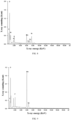
- FIG. 8 is an EDX energy spectrum diagram of the cathode material on the cathode electrode prepared according to Example 20. It can be seen from the figure that, the cathode material contains elements such as Ni, Co, Mn, Fe, O, P, C, and the like. These indicate that the surface of the ternary cathode material contains the component of lithium manganese iron phosphate.
- FIG. 9 is an EDX energy spectrum diagram of the cathode material on the cathode electrode prepared according to Example 26. It can be seen from the figure that, the cathode material contains elements such as Mn, Fe, O, P, C, and the like. These indicate that the surface of the lithium manganate cathode material contains the component of lithium manganese iron phosphate.
- FIG. 10 is an EDX energy spectrum diagram of the cathode material on the cathode electrode prepared according to Example 27. It can be seen from the figure that, the cathode material contains elements such as Co, Mn, Fe, O, P, C, and the like, which indicates that the surface of the lithium cobaltate cathode material contains the component of lithium manganese iron phosphate.
- the cathode materials on the cathode electrodes of Examples 19, 21 to 25, and Examples 28 to 36 have EDX energy spectrum diagrams similar to that of Examples 20, 26, and 27, and will not be repeated here.
- the cathode electrodes of Examples 20, 26, 27 and Comparative Examples 6 to 8 were assembled into coin half-cells, in which all half-cells used lithium sheets as the anode electrode.
- the half-cells made from the cathode electrodes of Example 20 and Comparative Example 6 were charged and discharged at a constant current and constant voltage with a current of 0.2 C in the range of 2.75 V to 4.3 V
- the half-cells made from the cathode electrodes of Example 26 and Comparative Example 7 were charged and discharged at a constant current and constant voltage with a current of 0.2 C in the range of 3.0 V to 4.3 V
- the half-cells made from the cathode electrodes of Example 27 and Comparative Example 8 were charged and discharged at a constant current and constant voltage with a current of 0.2 C in the range of 3.5 V to 4.35 V.
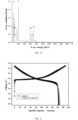
- FIG. 11 is an electrical test curve chart of the coin half-cells assembled from the cathode electrode of Example 20 and Comparative Example 6.
- the discharge specific capacity of the half-cells made from the cathode electrodes of Example 20 and Comparative Example 6 at a current of 0.2 C is 163.5 mAh/g and 162.8 mAh/g, respectively; this shows that the cathode additive of Example 1 does not affect the electrochemical performance of the ternary lithium ion battery.
- the electrical curve of the half-cell made from the cathode electrode of Example 20 has a bend with a small amplitude at the voltage platform of 3.6 V ⁇ 3.4 V, which should be the discharge platform of Fe 2+ /Fe 3+ in the lithium manganese iron phosphate, because the cathode additive in Example 2 is added in a less amount and the bending amplitude is smaller.
- FIG. 12 is an electrical test curve chart of the coin half-cells assembled from the cathode electrode of Example 26 and Comparative Example 7. It can be seen from the figure that, the discharge specific capacities of the half-cells made from the cathode electrodes of Example 26 and Comparative Example 7 at a current of 0.2 C is 109.0 mAh/g and 108.9 mAh/g, respectively; this shows that the cathode additive of Example 8 does not affect the electrochemical performance of the lithium manganate lithium ion battery.
- the electrical curve of Example 26 has a bend with a small amplitude at the voltage platform of 3.6 V ⁇ 3.4 V, which should be the discharge platform of Fe 2+ /Fe 3+ in the lithium manganese iron phosphate, because the cathode additive is added in a less amount and the bending amplitude is smaller.
- FIG. 13 is an electrical test curve chart of the coin half-cells assembled from the cathode electrode of Example 27 and Comparative Example 8. It can be seen from the figure that, the discharge specific capacities of the half-cells made from the cathode electrodes of Example 27 and Comparative Example 8 at a current of 0.2 C is 160.0 mAh/g and 158.7 mAh/g, respectively; this shows that the cathode additive of Example 9 does not affect the electrochemical performance of the lithium cobaltate lithium ion battery.
- the electrical curve of Example 27 has a bend with a small amplitude at the voltage platform of 3.6 V ⁇ 3.4 V, which should be the discharge platform of Fe 2+ /Fe 3+ in the lithium manganese iron phosphate, because the cathode additive is added in a less amount and the bending amplitude is smaller.
- FIG. 14 is a comparison diagram of the rate test of the coin half-cells assembled from the cathode electrode of Example 20 and Comparative Example 6.
- the two types of coin cells were tested three cycles of charge-discharge tests at currents of 0.2 C, 0.5 C, 1 C, and 2 C, respectively, and these data were counted in the comparison diagram. It can be found from the figure that the rate performance of Example 20 is similar to that of Comparative Example 6. This indicates that the cathode additive of Example 2 does not affect the rate performance of the ternary lithium ion battery.
- the cathode electrodes of Examples 19, 21 to 25, Examples 28 to 36, and Comparative Examples 2 to 5 were also assembled into coin half-cells according to the above method.
- the half-cells made from the cathode electrodes of Examples 19, 21 to 25, Examples 29 to 36, and Comparative Examples 2 to 5 were charged and discharged at a constant current and constant voltage with a current of 0.2 C, 1 C, and 2 C in the range of 2.75 V to 4.3 V
- the half-cells made from the cathode electrodes of Example 28 was charged and discharged at a constant current and constant voltage with a current of 0.2 C, 1 C, and 2 C in the range of 3.0 V to 4.3 V
- the discharge specific capacities of the half-cells made from the cathode electrodes of Example 19 to Example 36 and Comparative Example 2 to Comparative Example 8 with a current of 0.2 C, 1 C, and 2 C are shown in Table 5.
- the coin half-cells assembled from the cathode electrodes of Example 19 to Example 36 have discharge specific capacities of at least 110.3 mAh/g, 100.5 mAh/g and 89.2 mAh/g at a current of 0.2 C, 1 C and 2 C, respectively, with higher specific discharge capacity.
- the coin half-cell assembled from the cathode electrode of Example 25 has a specific discharge capacity of at least 198 mAh/g, 186.4 mAh/g and 175.4 mAh/g at a current of 0.2 C, 1 C and 2 C, respectively, which has a higher specific discharge capacity than that of the coin half-cells assembled from the cathode electrodes of Examples 26 to 36.
- the coin half-cells assembled from the cathode electrodes of Example 20 and Comparative Example 3 has the same conditions except for the different types of additives.
- the coin half-cell assembled from Example 20 has a specific discharge capacity at least of 163.9 mAh/g, 153.0 mAh/g and 136.8 mAh/g at a current of 0.2 C, 1 C, and 2 C, respectively; while the coin half-cell assembled from Comparative Example 3 has a specific discharge capacity at least of 140.7 mAh/g, 128.2 mAh/g and 115.3 mAh/g at a current of 0.2 C, 1 C, and 2 C, respectively, which is far worse than that of Example 20.
- Example 20 the lithium manganese iron phosphate with capacity was used as an additive, while in Comparative Example 3, a non-capacity aluminium oxide was used as an additive. If only inorganic materials are used as cathode additives to coat the cathode material, although it can form an artificial passivation layer, reduce the direct contact between the electrolyte and the cathode material, inhibit the dissolution of metal ions, and in extreme cases, it can relieve the irreversible reaction between the cathode material and the electrolyte and thus can make the cathode material have longer cycle and safety stability than the unmodified cathode material, because the inorganic material itself is inert and has no specific capacity, it will reduce the develop of the overallspecific capacity of the cathode material and reduce the energy density of the lithium ion battery.
- the direct contact between the electrolyte and the cathode material is reduced, and the rate performance of the cathode material is also reduced; when lithium manganese iron phosphate is used as a cathode additive, it can not only solve the safety problem of the battery, but at the same time it is a cathode active material itself, which can provide capacity, without significantly reducing the energy density and rate performance of the cathode material.
- the cathode additives containing lithium manganese iron phosphate or using lithium manganese iron phosphate powder the specific capacity of the cathode materials are all increased, and the rate performances are all better; while after using the cathode additives containing only inorganic materials or using inorganic material powder, the specific capacity of the cathode materials are all reduced, and the rate performances are all poor.
- the electrochemical performance of the coin half-cell assembled from the cathode electrode of Comparative Example 4 is far inferior to that of Example 20.
- the cathode electrode of Comparative Example 4 has a lower specific capacity and poor rate performance, and the cathode electrode of Example 20 has a higher specific capacity and better rate performance.
- the primary lithium manganese iron phosphate particles in the cathode additive are uniformly coated on the surface of the cathode material, but the lithium manganese iron phosphate powder is only mixed with the cathode material, the structure of the former is conducive to the improvement of the electrical conductivity of the lithium manganese iron phosphate particles, improving the development of the capacity of lithium manganese iron phosphate;
- the NCM (523)-lithium manganese iron phosphate cathode active material prepared by the fusion pre-coating method and the cathode material using the cathode additive containing lithium manganese iron phosphate have substantially the same specific capacity development and rate performance.
- the cathode electrodes pieces produced in Examples 20, 26, 27 and Comparative Examples 6 to 8 were made into soft-pack full-batteries, and the soft-pack full-batteries were subjected to needle-punch and overcharge tests and electrical performance test.
- the results of needle-punch, the results of overcharge test, and the specific capacities at a current of 1 C of the soft-pack full-batteries obtained from Examples 20, 26, 27 and Comparative Examples 6 to 8 are shown in Table 6.
- Needle-punch test a fully charged soft-pack full-battery was spiked using a smooth stainless steel needle with a diameter of 6 mm at a speed of 2.2cm/s, and observed for 1 hour. No explosion or ignition is a pass.
- the cathode materials on the cathode electrodes of Examples 19, 20 to 25, and 28 to 36 have safety performances similar to that of Examples 20, 26, and 27, and will not be repeated here.
Landscapes
- Chemical & Material Sciences (AREA)
- Chemical Kinetics & Catalysis (AREA)
- Electrochemistry (AREA)
- General Chemical & Material Sciences (AREA)
- Engineering & Computer Science (AREA)
- Materials Engineering (AREA)
- Manufacturing & Machinery (AREA)
- Composite Materials (AREA)
- Inorganic Chemistry (AREA)
- Crystallography & Structural Chemistry (AREA)
- Battery Electrode And Active Subsutance (AREA)
Claims (9)
- Procédé de préparation d'une électrode de cathode, comprenant les opérations suivantes :dans des conditions d'agitation continue, le mélange d'un liant avec du N-méthylpyrrolidone, et l'ajout d'un matériau conducteur, d'un additif de cathode et d'un matériau de cathode pour obtenir une suspension de cathode,l'additif de cathode ayant été préparé en dispersant un phosphate de lithium-manganèse-fer enrobé de carbone dans un solvant organique pour obtenir l'additif de cathode et dans lequel l'additif de cathode comprend, en pourcentage de masse, 10 % à 40 % de phosphate de lithium-manganèse-fer enrobé de carbone et le solvant organique, dans lequel le phosphate de lithium-manganèse-fer enrobé de carbone est dispersé dans le solvant organique, et un diamètre médian des particules du phosphate de lithium-manganèse-fer enrobé de carbone est de 30 nm à 100 nm, un rapport de masse du matériau de cathode au phosphate de lithium-manganèse-fer enrobé de carbone dans l'additif de cathode est 80:20 à 99: 1, etla préparation de la suspension de cathode en l'électrode cathode,dans lequel le matériau de cathode est au moins un matériau sélectionné parmi un groupe constitué par un matériau ternaire de nickel-cobalt-manganèse, un matériau ternaire de nickel-cobalt-aluminium, un oxyde de lithium-nickel-manganèse, le manganate de lithium et le cobaltate de lithium.
- Procédé de préparation de l'électrode de cathode selon la revendication 1, dans lequel le diamètre médian des particules du phosphate de lithium-manganèse-fer enrobé de carbone est de 60 nm à 80 nm.
- Procédé de préparation de l'additif de cathode selon la revendication 1, dans lequel l'additif de cathode comprend un matériau inorganique en un pourcentage de masse inférieur à 0,5 %, dans lequel le matériau inorganique est au moins un matériau sélectionné parmi un groupe constitué par un nano-oxyde d'aluminium, un nano-oxyde de titane et un nano-oxyde de magnésium.
- Procédé de préparation de l'additif de cathode selon la revendication 1, dans lequel un pourcentage en masse de carbone dans le phosphate de lithium-manganèse-fer enrobé de carbone est de 2 % à 15 %.
- Procédé de préparation de l'additif de cathode selon la revendication 1, dans lequel le solvant organique est au moins un solvant sélectionné parmi un groupe constitué par le N-méthylpyrrolidone et le N,N-diméthylformamide.
- Procédé de préparation de l'additif de cathode selon la revendication 1, dans lequel l'additif de cathode comprend l'addition d'un liant en un pourcentage en masse inférieur à 2 %, optionnellement dans lequel le liant est du fluorure de polyvinylidène ou du caoutchouc styrène-butadiène.
- Procédé de préparation de l'additif de cathode selon l'une quelconque des revendications 1 à 6, dans lequel l'additif de cathode comprend un agent conducteur en un pourcentage en masse inférieur à 10 %, optionnellement dans lequel l'agent conducteur est au moins un élément sélectionné parmi un groupe constitué par le noir d'acétylène, le noir de Ketjen, le graphène et des nano-tubes de carbone.
- Procédé de préparation de l'additif de cathode selon la revendication 1, dans lequel un pourcentage en masse de matières solides dans l'additif de cathode est de 10 % à 45 %.
- Procédé de préparation de l'additif de cathode selon la revendication 8, dans lequel le pourcentage en masse de matières solides dans l'additif de cathode est de 25 % à 30 %.
Applications Claiming Priority (1)
| Application Number | Priority Date | Filing Date | Title |
|---|---|---|---|
| PCT/CN2018/108383 WO2020062046A1 (fr) | 2018-09-28 | 2018-09-28 | Additif d'électrode positive et son procédé de préparation, électrode positive et son procédé de préparation, et batterie au lithium-ion |
Publications (4)
| Publication Number | Publication Date |
|---|---|
| EP3859825A1 EP3859825A1 (fr) | 2021-08-04 |
| EP3859825A4 EP3859825A4 (fr) | 2022-04-27 |
| EP3859825C0 EP3859825C0 (fr) | 2025-02-19 |
| EP3859825B1 true EP3859825B1 (fr) | 2025-02-19 |
Family
ID=65462550
Family Applications (1)
| Application Number | Title | Priority Date | Filing Date |
|---|---|---|---|
| EP18935918.5A Active EP3859825B1 (fr) | 2018-09-28 | 2018-09-28 | Additif d'électrode positive et son procédé de préparation, électrode positive et son procédé de préparation, et batterie au lithium-ion |
Country Status (8)
| Country | Link |
|---|---|
| US (1) | US12100830B2 (fr) |
| EP (1) | EP3859825B1 (fr) |
| JP (1) | JP7158595B2 (fr) |
| KR (1) | KR102699307B1 (fr) |
| CN (1) | CN109417162B (fr) |
| ES (1) | ES3014483T3 (fr) |
| PL (1) | PL3859825T3 (fr) |
| WO (1) | WO2020062046A1 (fr) |
Families Citing this family (16)
| Publication number | Priority date | Publication date | Assignee | Title |
|---|---|---|---|---|
| CN109888257A (zh) * | 2019-04-03 | 2019-06-14 | 山东星火科学技术研究院 | 一种石墨烯包覆改性锂离子电池正极材料及其制备方法 |
| US20210112669A1 (en) * | 2019-10-09 | 2021-04-15 | National Taiwan University Of Science And Technology | Conductive slurry and plating method using the same |
| CN110993894A (zh) * | 2019-11-25 | 2020-04-10 | 宁波致良新能源有限公司 | 正极添加剂及其制备方法、正极及其制备方法和锂离子电池 |
| CN112054202A (zh) * | 2020-09-10 | 2020-12-08 | 辽宁九夷锂能股份有限公司 | 一种高能量大倍率锂电池正极添加剂及其制备方法和含有正极添加剂的正极片 |
| KR102921923B1 (ko) * | 2021-03-08 | 2026-02-03 | 에스케이온 주식회사 | 리튬 이차전지용 양극 및 이를 포함하는 리튬 이차전지 |
| CN113193199A (zh) * | 2021-04-30 | 2021-07-30 | 中国科学院宁波材料技术与工程研究所 | 一种石墨烯-锂离子导体材料复合导电浆料、其制备方法及应用 |
| KR102798805B1 (ko) * | 2021-06-03 | 2025-04-23 | 주식회사 엘지에너지솔루션 | 리튬 이차전지용 양극 및 이를 포함하는 리튬 이차전지 |
| CN113247962B (zh) * | 2021-06-26 | 2021-10-29 | 深圳中科精研科技有限公司 | 电池正极材料及快速合成电池正极材料的方法 |
| US12412884B2 (en) | 2021-10-19 | 2025-09-09 | Lg Chem, Ltd. | Manufacturing method of cathode additives for lithium secondary battery |
| CN114203991B (zh) * | 2021-12-01 | 2024-06-11 | 远景动力技术(江苏)有限公司 | 正极材料添加剂、正极及锂离子电池 |
| US20230207807A1 (en) * | 2021-12-24 | 2023-06-29 | Lg Energy Solution, Ltd. | Positive Electrode Slurry Composition and Lithium Secondary Battery Manufactured Using the Same |
| CN115832236B (zh) * | 2022-03-25 | 2025-02-21 | 宁德时代新能源科技股份有限公司 | 磷酸铁锂正极材料、其制备方法、正极极片、锂离子电池、电池模块、电池包和用电装置 |
| CN115148945B (zh) * | 2022-06-24 | 2023-03-07 | 广东墨睿科技有限公司 | 一种高镍三元正极材料的改性方法 |
| CN115954460A (zh) * | 2023-02-17 | 2023-04-11 | 河南佰利新能源材料有限公司 | 一种磷酸锰铁锂正极材料及其制备方法和应用 |
| CN116646470A (zh) * | 2023-07-18 | 2023-08-25 | 宁德时代新能源科技股份有限公司 | 正极极片、正极极片的制备方法、电池和用电设备 |
| CN119297186B (zh) * | 2024-09-09 | 2025-11-11 | 湖北亿纬动力有限公司 | 一种复合正极浆料的匀浆方法 |
Family Cites Families (13)
| Publication number | Priority date | Publication date | Assignee | Title |
|---|---|---|---|---|
| JP5381024B2 (ja) * | 2008-11-06 | 2014-01-08 | 株式会社Gsユアサ | リチウム二次電池用正極及びリチウム二次電池 |
| KR101810259B1 (ko) * | 2010-03-19 | 2017-12-18 | 도다 고교 가부시끼가이샤 | 인산망간철리튬 입자 분말의 제조 방법, 인산망간철리튬 입자 분말, 및 상기 입자 분말을 이용한 비수전해질 이차 전지 |
| CN103500829B (zh) * | 2013-08-15 | 2016-12-28 | 江苏华东锂电技术研究院有限公司 | 磷酸亚铁锂的制备方法 |
| EP3018740B1 (fr) | 2013-09-02 | 2017-11-01 | LG Chem, Ltd. | Anode pour batterie rechargeable et batterie rechargeable contenant celle-ci |
| CN104425845A (zh) | 2013-09-09 | 2015-03-18 | 北京国能电池科技有限公司 | 一种高能量密度锂离子动力电池及其制造方法 |
| CN105024047B (zh) * | 2014-04-23 | 2017-06-16 | 宁德时代新能源科技股份有限公司 | 锂离子二次电池及其复合正极活性材料及制备方法 |
| CN105977456A (zh) | 2015-03-12 | 2016-09-28 | 中国科学院成都有机化学有限公司 | 一种制备LiMn1-xFexPO4/C复合材料的固相合成方法 |
| US11127937B2 (en) * | 2015-11-25 | 2021-09-21 | Research & Business Foundation Sungkyunkwan University | Method of manufacturing carbon-coated electrode active material and electrode active material manufactured by the method |
| CN105304880B (zh) | 2015-11-27 | 2019-05-03 | 上海空间电源研究所 | 一种锂离子电池用混合正极材料 |
| US10910679B2 (en) * | 2016-07-19 | 2021-02-02 | Uchicago Argonne, Llc | Photo-assisted fast charging of lithium manganese oxide spinel (LiMn2O4) in lithium-ion batteries |
| CN106129365B (zh) * | 2016-08-19 | 2017-05-17 | 骆驼集团新能源电池有限公司 | 一种高安全性磷酸锰铁锂电池 |
| CN106384807B (zh) | 2016-11-24 | 2018-11-02 | 山东精工电子科技有限公司 | 一种锂离子电池正极片及其制备方法 |
| CN107546379B (zh) | 2017-08-18 | 2020-02-28 | 宁波致良新能源有限公司 | 磷酸锰铁锂-三元材料复合正极材料及其制备方法 |
-
2018
- 2018-09-28 CN CN201880001558.8A patent/CN109417162B/zh active Active
- 2018-09-28 WO PCT/CN2018/108383 patent/WO2020062046A1/fr not_active Ceased
- 2018-09-28 EP EP18935918.5A patent/EP3859825B1/fr active Active
- 2018-09-28 JP JP2021542236A patent/JP7158595B2/ja active Active
- 2018-09-28 PL PL18935918.5T patent/PL3859825T3/pl unknown
- 2018-09-28 US US17/277,809 patent/US12100830B2/en active Active
- 2018-09-28 ES ES18935918T patent/ES3014483T3/es active Active
- 2018-09-28 KR KR1020217012856A patent/KR102699307B1/ko active Active
Also Published As
| Publication number | Publication date |
|---|---|
| CN109417162B (zh) | 2021-09-21 |
| ES3014483T3 (en) | 2025-04-22 |
| JP2022502830A (ja) | 2022-01-11 |
| CN109417162A (zh) | 2019-03-01 |
| US20210351395A1 (en) | 2021-11-11 |
| KR102699307B1 (ko) | 2024-08-30 |
| EP3859825A4 (fr) | 2022-04-27 |
| EP3859825C0 (fr) | 2025-02-19 |
| PL3859825T3 (pl) | 2025-06-02 |
| EP3859825A1 (fr) | 2021-08-04 |
| US12100830B2 (en) | 2024-09-24 |
| JP7158595B2 (ja) | 2022-10-21 |
| WO2020062046A1 (fr) | 2020-04-02 |
| KR20210064360A (ko) | 2021-06-02 |
Similar Documents
| Publication | Publication Date | Title |
|---|---|---|
| EP3859825B1 (fr) | Additif d'électrode positive et son procédé de préparation, électrode positive et son procédé de préparation, et batterie au lithium-ion | |
| CN115020696B (zh) | 正极活性材料、电化学装置和电子设备 | |
| CN115020678B (zh) | 正极活性材料、电化学装置和电子设备 | |
| CN112542589B (zh) | 一种正极预锂化材料的制备方法、产物及应用 | |
| CN105185987B (zh) | 正极材料及锂离子二次电池 | |
| JP5961911B2 (ja) | 出力特性と安全性が向上した混合正極活物質及びこれを含むリチウム二次電池 | |
| CN112542583A (zh) | 一种正极活性材料及包括该正极活性材料的高电压锂离子电池 | |
| CN112701277A (zh) | 一种锂离子电池预锂化添加剂及其应用 | |
| JP7807137B2 (ja) | 負極およびこれを含む二次電池 | |
| CN112563462A (zh) | 一种高电压复合正极材料及包含该材料的锂离子电池 | |
| KR20130134949A (ko) | 혼합 양극활물질 및 이를 포함하는 리튬이차전지 | |
| CN102306791A (zh) | 一种碳包覆非化学计量比氧化锂铁磷材料的制备方法 | |
| CN113937255A (zh) | 一种锂离子电池复合正极材料及其制备方法和应用 | |
| CN115881889A (zh) | 一种锂离子电池 | |
| KR20110108301A (ko) | 비수 전해질 이차 전지 및 비수 전해질 이차 전지의 제조 방법 | |
| CN118908285A (zh) | 磷酸锰铁锂包覆锰酸锂正极材料及其制备方法 | |
| EP3553852B1 (fr) | Batterie d'alimentation et plaque d'électrode positive de celle-ci | |
| CN110993894A (zh) | 正极添加剂及其制备方法、正极及其制备方法和锂离子电池 | |
| CN113097479B (zh) | 一种快充型锂离子电池负极粉的制备方法及其在锂离子电池中的应用 | |
| CN115394951A (zh) | 一种二次电池的负极活性材料以及一种二次电池 | |
| EP4447142B1 (fr) | Cellule et dispositif électronique | |
| CN117219835A (zh) | 一种电芯及其制备方法和应用其的锂电池 | |
| CN116864650A (zh) | 一种锂离子电池的正极活性材料及其制备方法 | |
| WO2023143516A1 (fr) | Feuille d'électrode positive à capacité de débit élevée, à cycle long et à haute sécurité destinée à être utilisée dans une batterie au lithium, ainsi que son procédé de préparation et son application | |
| CN115312746A (zh) | 一种正极材料及其制备方法 |
Legal Events
| Date | Code | Title | Description |
|---|---|---|---|
| STAA | Information on the status of an ep patent application or granted ep patent |
Free format text: STATUS: THE INTERNATIONAL PUBLICATION HAS BEEN MADE |
|
| PUAI | Public reference made under article 153(3) epc to a published international application that has entered the european phase |
Free format text: ORIGINAL CODE: 0009012 |
|
| STAA | Information on the status of an ep patent application or granted ep patent |
Free format text: STATUS: REQUEST FOR EXAMINATION WAS MADE |
|
| 17P | Request for examination filed |
Effective date: 20210423 |
|
| AK | Designated contracting states |
Kind code of ref document: A1 Designated state(s): AL AT BE BG CH CY CZ DE DK EE ES FI FR GB GR HR HU IE IS IT LI LT LU LV MC MK MT NL NO PL PT RO RS SE SI SK SM TR |
|
| DAV | Request for validation of the european patent (deleted) | ||
| DAX | Request for extension of the european patent (deleted) | ||
| A4 | Supplementary search report drawn up and despatched |
Effective date: 20220330 |
|
| RIC1 | Information provided on ipc code assigned before grant |
Ipc: H01M 10/052 20100101ALN20220324BHEP Ipc: H01M 4/58 20100101ALI20220324BHEP Ipc: H01M 4/525 20100101ALI20220324BHEP Ipc: H01M 4/505 20100101ALI20220324BHEP Ipc: H01M 4/36 20060101ALI20220324BHEP Ipc: H01M 10/0525 20100101ALI20220324BHEP Ipc: H01M 4/62 20060101ALI20220324BHEP Ipc: H01M 4/1391 20100101ALI20220324BHEP Ipc: H01M 4/131 20100101AFI20220324BHEP |
|
| STAA | Information on the status of an ep patent application or granted ep patent |
Free format text: STATUS: EXAMINATION IS IN PROGRESS |
|
| 17Q | First examination report despatched |
Effective date: 20231124 |
|
| RIC1 | Information provided on ipc code assigned before grant |
Ipc: H01M 10/052 20100101ALN20240715BHEP Ipc: H01M 4/58 20100101ALI20240715BHEP Ipc: H01M 4/525 20100101ALI20240715BHEP Ipc: H01M 4/505 20100101ALI20240715BHEP Ipc: H01M 4/36 20060101ALI20240715BHEP Ipc: H01M 10/0525 20100101ALI20240715BHEP Ipc: H01M 4/62 20060101ALI20240715BHEP Ipc: H01M 4/1391 20100101ALI20240715BHEP Ipc: H01M 4/131 20100101AFI20240715BHEP |
|
| GRAP | Despatch of communication of intention to grant a patent |
Free format text: ORIGINAL CODE: EPIDOSNIGR1 |
|
| STAA | Information on the status of an ep patent application or granted ep patent |
Free format text: STATUS: GRANT OF PATENT IS INTENDED |
|
| INTG | Intention to grant announced |
Effective date: 20240916 |
|
| GRAS | Grant fee paid |
Free format text: ORIGINAL CODE: EPIDOSNIGR3 |
|
| GRAA | (expected) grant |
Free format text: ORIGINAL CODE: 0009210 |
|
| STAA | Information on the status of an ep patent application or granted ep patent |
Free format text: STATUS: THE PATENT HAS BEEN GRANTED |
|
| AK | Designated contracting states |
Kind code of ref document: B1 Designated state(s): AL AT BE BG CH CY CZ DE DK EE ES FI FR GB GR HR HU IE IS IT LI LT LU LV MC MK MT NL NO PL PT RO RS SE SI SK SM TR |
|
| REG | Reference to a national code |
Ref country code: GB Ref legal event code: FG4D |
|
| REG | Reference to a national code |
Ref country code: CH Ref legal event code: EP |
|
| REG | Reference to a national code |
Ref country code: IE Ref legal event code: FG4D |
|
| REG | Reference to a national code |
Ref country code: DE Ref legal event code: R096 Ref document number: 602018079478 Country of ref document: DE |
|
| U01 | Request for unitary effect filed |
Effective date: 20250313 |
|
| REG | Reference to a national code |
Ref country code: ES Ref legal event code: FG2A Ref document number: 3014483 Country of ref document: ES Kind code of ref document: T3 Effective date: 20250422 |
|
| U07 | Unitary effect registered |
Designated state(s): AT BE BG DE DK EE FI FR IT LT LU LV MT NL PT RO SE SI Effective date: 20250319 |
|
| PG25 | Lapsed in a contracting state [announced via postgrant information from national office to epo] |
Ref country code: RS Free format text: LAPSE BECAUSE OF FAILURE TO SUBMIT A TRANSLATION OF THE DESCRIPTION OR TO PAY THE FEE WITHIN THE PRESCRIBED TIME-LIMIT Effective date: 20250519 |
|
| PG25 | Lapsed in a contracting state [announced via postgrant information from national office to epo] |
Ref country code: IS Free format text: LAPSE BECAUSE OF FAILURE TO SUBMIT A TRANSLATION OF THE DESCRIPTION OR TO PAY THE FEE WITHIN THE PRESCRIBED TIME-LIMIT Effective date: 20250619 Ref country code: NO Free format text: LAPSE BECAUSE OF FAILURE TO SUBMIT A TRANSLATION OF THE DESCRIPTION OR TO PAY THE FEE WITHIN THE PRESCRIBED TIME-LIMIT Effective date: 20250519 |
|
| PG25 | Lapsed in a contracting state [announced via postgrant information from national office to epo] |
Ref country code: HR Free format text: LAPSE BECAUSE OF FAILURE TO SUBMIT A TRANSLATION OF THE DESCRIPTION OR TO PAY THE FEE WITHIN THE PRESCRIBED TIME-LIMIT Effective date: 20250219 |
|
| PG25 | Lapsed in a contracting state [announced via postgrant information from national office to epo] |
Ref country code: GR Free format text: LAPSE BECAUSE OF FAILURE TO SUBMIT A TRANSLATION OF THE DESCRIPTION OR TO PAY THE FEE WITHIN THE PRESCRIBED TIME-LIMIT Effective date: 20250520 |
|
| PG25 | Lapsed in a contracting state [announced via postgrant information from national office to epo] |
Ref country code: SM Free format text: LAPSE BECAUSE OF FAILURE TO SUBMIT A TRANSLATION OF THE DESCRIPTION OR TO PAY THE FEE WITHIN THE PRESCRIBED TIME-LIMIT Effective date: 20250219 |
|
| PGFP | Annual fee paid to national office [announced via postgrant information from national office to epo] |
Ref country code: TR Payment date: 20250922 Year of fee payment: 8 Ref country code: PL Payment date: 20250922 Year of fee payment: 8 |
|
| U20 | Renewal fee for the european patent with unitary effect paid |
Year of fee payment: 8 Effective date: 20250908 |
|
| PGFP | Annual fee paid to national office [announced via postgrant information from national office to epo] |
Ref country code: GB Payment date: 20250825 Year of fee payment: 8 |
|
| PG25 | Lapsed in a contracting state [announced via postgrant information from national office to epo] |
Ref country code: CZ Free format text: LAPSE BECAUSE OF FAILURE TO SUBMIT A TRANSLATION OF THE DESCRIPTION OR TO PAY THE FEE WITHIN THE PRESCRIBED TIME-LIMIT Effective date: 20250219 |
|
| PG25 | Lapsed in a contracting state [announced via postgrant information from national office to epo] |
Ref country code: SK Free format text: LAPSE BECAUSE OF FAILURE TO SUBMIT A TRANSLATION OF THE DESCRIPTION OR TO PAY THE FEE WITHIN THE PRESCRIBED TIME-LIMIT Effective date: 20250219 |
|
| PLBE | No opposition filed within time limit |
Free format text: ORIGINAL CODE: 0009261 |
|
| STAA | Information on the status of an ep patent application or granted ep patent |
Free format text: STATUS: NO OPPOSITION FILED WITHIN TIME LIMIT |
|
| 26N | No opposition filed |
Effective date: 20251120 |
|
| PGFP | Annual fee paid to national office [announced via postgrant information from national office to epo] |
Ref country code: ES Payment date: 20251020 Year of fee payment: 8 |
|
| U1N | Appointed representative for the unitary patent procedure changed after the registration of the unitary effect |
Representative=s name: MARKS & CLERK LLP; GB |