EP3859893A1 - Antennensystem - Google Patents
Antennensystem Download PDFInfo
- Publication number
- EP3859893A1 EP3859893A1 EP20153977.2A EP20153977A EP3859893A1 EP 3859893 A1 EP3859893 A1 EP 3859893A1 EP 20153977 A EP20153977 A EP 20153977A EP 3859893 A1 EP3859893 A1 EP 3859893A1
- Authority
- EP
- European Patent Office
- Prior art keywords
- conductive element
- feed
- ground plane
- antenna radiator
- antenna
- Prior art date
- Legal status (The legal status is an assumption and is not a legal conclusion. Google has not performed a legal analysis and makes no representation as to the accuracy of the status listed.)
- Granted
Links
Images



Classifications
-
- H—ELECTRICITY
- H01—ELECTRIC ELEMENTS
- H01Q—ANTENNAS, i.e. RADIO AERIALS
- H01Q1/00—Details of, or arrangements associated with, antennas
- H01Q1/50—Structural association of antennas with earthing switches, lead-in devices or lightning protectors
-
- H—ELECTRICITY
- H01—ELECTRIC ELEMENTS
- H01Q—ANTENNAS, i.e. RADIO AERIALS
- H01Q9/00—Electrically-short antennas having dimensions not more than twice the operating wavelength and consisting of conductive active radiating elements
- H01Q9/04—Resonant antennas
- H01Q9/0407—Substantially flat resonant element parallel to ground plane, e.g. patch antenna
- H01Q9/045—Substantially flat resonant element parallel to ground plane, e.g. patch antenna with particular feeding means
- H01Q9/0457—Substantially flat resonant element parallel to ground plane, e.g. patch antenna with particular feeding means electromagnetically coupled to the feed line
-
- H—ELECTRICITY
- H01—ELECTRIC ELEMENTS
- H01Q—ANTENNAS, i.e. RADIO AERIALS
- H01Q1/00—Details of, or arrangements associated with, antennas
- H01Q1/12—Supports; Mounting means
- H01Q1/22—Supports; Mounting means by structural association with other equipment or articles
- H01Q1/24—Supports; Mounting means by structural association with other equipment or articles with receiving set
-
- H—ELECTRICITY
- H01—ELECTRIC ELEMENTS
- H01Q—ANTENNAS, i.e. RADIO AERIALS
- H01Q1/00—Details of, or arrangements associated with, antennas
- H01Q1/12—Supports; Mounting means
- H01Q1/22—Supports; Mounting means by structural association with other equipment or articles
- H01Q1/24—Supports; Mounting means by structural association with other equipment or articles with receiving set
- H01Q1/241—Supports; Mounting means by structural association with other equipment or articles with receiving set used in mobile communications, e.g. GSM
- H01Q1/246—Supports; Mounting means by structural association with other equipment or articles with receiving set used in mobile communications, e.g. GSM specially adapted for base stations
-
- H—ELECTRICITY
- H01—ELECTRIC ELEMENTS
- H01Q—ANTENNAS, i.e. RADIO AERIALS
- H01Q1/00—Details of, or arrangements associated with, antennas
- H01Q1/36—Structural form of radiating elements, e.g. cone, spiral, umbrella; Particular materials used therewith
-
- H—ELECTRICITY
- H01—ELECTRIC ELEMENTS
- H01Q—ANTENNAS, i.e. RADIO AERIALS
- H01Q1/00—Details of, or arrangements associated with, antennas
- H01Q1/48—Earthing means; Earth screens; Counterpoises
-
- H—ELECTRICITY
- H01—ELECTRIC ELEMENTS
- H01Q—ANTENNAS, i.e. RADIO AERIALS
- H01Q9/00—Electrically-short antennas having dimensions not more than twice the operating wavelength and consisting of conductive active radiating elements
- H01Q9/04—Resonant antennas
- H01Q9/0407—Substantially flat resonant element parallel to ground plane, e.g. patch antenna
- H01Q9/0478—Substantially flat resonant element parallel to ground plane, e.g. patch antenna with means for suppressing spurious modes, e.g. cross polarisation
Definitions
- Embodiments of the present disclosure relate to an antenna system, a feed system and an antenna.
- a base station transceiver (or user equipment transceiver) normally comprises transceiver circuitry interconnected to an antenna radiator via a high-quality filter.
- the high-quality filters can be quite large.
- the base station transceiver (or user equipment transceiver) has a large number of antenna radiators then a correspondingly large number of filters are required. This can occupy a large volume.
- an antenna system comprising:
- the feed element extends substantially parallel to the first conductive element.
- the first conductive element circumscribes the feed element.
- the first conductive element extends towards the ground plane and has an axis of rotational symmetry that extends towards the ground plane and the feed element extends towards the antenna radiator along an axis of rotational symmetry that extends towards the antenna radiator, wherein the first conductive element and the feed element are substantially coaxial.
- the first conductive element is shaped substantially as a hollow cylinder.
- the antenna system further comprises at least one second conductive element extending the ground plane towards the antenna radiator, wherein the second conductive element is spatially separated from the first conductive element.
- the feed element extends towards the antenna radiator in a direction substantially parallel to a direction in which the first conductive element extends the antenna radiator and substantially parallel to a direction in which a second conductive element extends the ground plane.
- the first conductive element circumscribes a first portion of a length of the feed element and the second conductive element circumscribes a different, second portion of the length of the feed element.
- the first conductive element extends towards the ground plane and has an axis of rotational symmetry that extends towards the ground plane
- the second conductive element extends towards the antenna radiator and has an axis of rotational symmetry that extends towards the antenna radiator
- the feed element extends towards the antenna radiator along an axis of rotational symmetry that extends towards the antenna radiator, wherein the axes of the first conductive element, the second conductive element and the feed element are coaxial.
- the first conductive element is shaped substantially as a hollow cylinder having a first diameter and the second conductive element is shaped substantially as a hollow cylinder having a second, different diameter.
- the first conductive element is closer to the feed element than the second conductive element.
- the feed element is an open-ended feed configured to contactlessly feed the antenna radiator.
- the antenna radiator is a patch antenna.
- the feed element, the first conductive element, and, if present, the second conductive element are configured to provide a narrowband resonant frequency feed for the antenna radiator, wherein a narrowband resonant frequency of the feed is dependent upon location and dimensions of the feed element, the first conductive element and, if present, the second conductive element.
- At least one of the dimensions of one or more of the first conductive element, the feed element and, if present, the second conductive element are variable to tune the narrowband resonant frequency of the narrowband resonant frequency feed.
- the first conductive element is positioned closer to an edge of the radiator than a center of the radiator.
- the first conductive element extends the antenna radiator towards the ground plane at a first location and the feed element is configured to provide a radio frequency feed, at the first location, for the antenna radiator, the antenna system further comprising:
- the first narrowband resonant frequency feed and the second narrowband resonant frequency feed are configured to have different narrowband resonant frequencies or wherein the first narrowband resonant frequency feed and the second narrowband resonant frequency feed are configured to have the same resonant frequency but are located for orthogonal polarization.
- a network access node or a portable electronic device comprises one or more antenna systems.
- a narrowband resonant frequency feed system for an antenna radiator comprising:
- an antenna for use with the narrowband resonant frequency system comprising:
- FIG. 1 illustrates an example of an antenna system 10.
- the antenna system 10 comprises a ground plane 30, an antenna radiator 20, a first conductive element 22 and a feed element 42.
- the antenna radiator 20 is separated from and fully or partially overlaps the ground plane 30.
- the first conductive element 22 extends the antenna radiator 20 towards the ground plane 30.
- the feed element 42 is configured to provide a radio frequency feed for the antenna radiator 20.
- the feed element 42 is spatially separated from the first conductive element 22 and the antenna radiator 20.
- the antenna radiator 20 is substantially planar.
- the ground plane 30 is substantially planar.
- the antenna radiator 20 and/or the ground plane 30 can be any shape and can, for example, be wholly or partially planar and/or wholly or partially non-planar and/or curved. In some examples the the antenna radiator 20 and the ground plane 30 both having planar and non-planar portions.
- the first conductive element 22 extends the antenna radiator 20 in the sense that there is a galvanic current path (direct current path) from the antenna radiator 20 to the first conductive element 22.
- the first conductive element 22 may be an integral part of the antenna radiator 20 or may be attached to the antenna radiator 20.
- the feed element 42 is proximal to the first conductive element 22 and the feed element 42 is capacitively coupled to the first conductive element 22.
- the feed element 42 is therefore coupled to the antenna radiator 20 via the first conductive element 22.
- the feed element 42 extends towards the antenna radiator 20 in a direction substantially parallel to a direction in which the first conductive element 22 extends the antenna radiator 20.
- the feed element 42 in this example (but not necessarily all examples) is elongate and is substantially longer than it is wide.
- the feed element 42 extends in the lengthwise direction towards the antenna radiator 20 in the direction substantially parallel to the direction in which the first conductive element 42 extends the antenna radiator 20.
- the feed element 42 is proximal to the first conductive element 22, in this example, in the sense that it is significantly closer than the length of the feed element and, in this example, but not necessarily all examples, is closer than the lateral dimension of the feed element 42.
- the first conductive element 22 circumscribes at least a portion of the feed element 42.
- circumscribes means that the feed element 42 is surrounded on four sides by the first conductive element 22.
- the term circumscribes does not necessarily imply a circular cross section for the first conductive element 22.
- the first conductive element 22 extends towards the ground plane 30 and has an axis 24 of rotational symmetry that extends towards the ground plane 30.
- the feed element 42 extends towards the antenna radiator 20 along an axis 44.
- the axis 24 and the axis 44 are parallel.
- the feed element 42 extends towards the antenna radiator 20 along an axis 44 of rotational symmetry that extends towards the antenna radiator 20 and the axis 24 and the axis 44 are aligned.
- the first conductive element 22 and the feed element 42 are consequentially substantially coaxial.
- the first conductive element 22 is shaped substantially as a hollow cylinder.
- other shapes are possible, and not limited to, such as shapes that have a square or rectangular cross section.
- the cross section of the first conductive element does not need to have a constant area and can for example taper inwards, or outwards or otherwise vary as it extends from the antenna radiator 20 towards the ground plane 30.
- an antenna radiator 20 has a physical and galvanic connection with the first conductive element 22.
- the first conductive element 22 consequently extends the antenna radiator 20.
- the antenna radiator 20 is spatially separated from the ground plane 30 and there is no galvanic connection between the antenna radiator 20 and the ground plane 30.
- the antenna radiator 20 is spatially separated from the feed element 42 and there is no galvanic connection between the antenna radiator 20 and the feed element 42.
- the first conductive element 22 is spatially separated from the ground plane 30 and there is no galvanic connection between the first conductive element 22 and the ground plane 30.
- the first conductive element 22 is spatially separated from the feed element 42 and there is no galvanic connection between the first conductive element 22 and the feed element 42.
- the spatial separation between the first conductive element 22 and the feed element 42 is small and there is capacitive coupling between the first conductive element 22 and the feed element 42.
- the ground plane 30 is spatially separated from the feed element 42 and there is no galvanic connect between the ground plane 30 and feed element 42.
- FIG. 2 illustrates an example of the antenna system 10 previously described with reference to FIG. 1 .
- the antenna system 10 further comprises a second conductive element 32 extending the ground plane 30 towards the antenna radiator 20 to capacitively couple with the first conductive element 22.
- the second conductive element 32 is spatially separated from the first conductive element 22.
- the second conductive element 32 extends the ground plane 30 in the sense that there is a direct current path between the ground plane 30 and the second conductive element 32.
- the second conductive element 32 may be an integral part of the ground plane 30 or may be attached to the ground plane 30.
- the second conductive element 32 is proximal to the first conductive element 22 in the illustrated example. This enables good capacitive coupling between the first conductive element 22 and the second conductive element 32.
- the feed element 42 extends towards the antenna radiator 20 in a direction substantially parallel to a direction in which the first conductive element 22 extends the antenna radiator 20 and substantially parallel to a direction in which the second conductive element 32 extends the ground plane 30.
- the feed element 42 in this example (but not necessarily all examples) is elongate and is substantially longer than it is wide.
- the feed element 42 extends in the lengthwise direction towards the antenna radiator 20 in the direction substantially parallel to the direction in which the first conductive element 22 extends the antenna radiator 20 and substantially parallel to a direction in which the second conductive element 32 extends the ground plane 30.
- the feed element 42 is proximal to the first conductive element 22, in this example, in the sense that it is significantly closer than the length of the feed element and, in this example, but not necessarily all examples, is closer than the lateral dimension of the feed element 42.
- the second conductive element 32 is proximal to the first conductive element 22, in this example, in the sense that it is significantly closer than the length of the feed element 42 and, in this example, but not necessarily all examples, is closer than the lateral dimension of the feed element 42.
- the first conductive element 22 circumscribes a first portion of a length of the feed element 42 and the second conductive element 32 circumscribes a different, second portion of the length of the feed element 42.
- circumscribes means that the feed element 42 is surrounded on four sides by a respective conductive element 22, 32.
- the term circumscribes does not necessarily imply a circular cross section for the respective conductive element 22, 32.
- first conductive element 22 and the second conductive element 32 overlap, and a portion of the length of the feed element 42 is circumscribed by both the first conductive element 22 and the second conductive element 32.
- circumscribes means that the portion of the feed element 42 is surrounded on four sides by respective conductive elements 22, 32.
- the term circumscribes does not necessarily imply a circular cross section for the respective conductive elements 22, 32.
- the first conductive element 22 extends towards the ground plane 30 and has an axis 24 of rotational symmetry that extends towards the ground plane 30.
- the second conductive element 32 extends towards the antenna radiator 20 and has an axis 44 of rotational symmetry that extends towards the antenna radiator 20.
- the feed element 42 extends towards the antenna radiator 20 along an axis 44.
- the axes are parallel.
- the feed element 42 extends towards the antenna radiator 20 along an axis 44 of rotational symmetry that extends towards the antenna radiator 20 and the axes are aligned.
- the first conductive element 22, the second conductive element 32 and the feed element 42 are consequentially substantially coaxial.
- the first conductive element 22 is shaped substantially as a hollow cylinder that has a first diameter d 1 .
- d 1 first diameter
- other shapes are possible, and not limited to, such as shapes that have a square or rectangular cross section.
- the cross section of the first conductive element 22 does not need to have a constant area and can for example taper inwards, or outwards or otherwise vary as it extends from the antenna radiator 20 towards the ground plane 30.
- the second conductive element 32 is shaped substantially as a hollow cylinder that has a second diameter d 2 .
- the cross section of the second conductive element 32 does not need to have a constant area and can for example taper inwards, or outwards or otherwise vary as it extends from the ground plane 30 towards the antenna radiator 20.
- first and second conductive elements 22, 32 are cylinders and the second diameter d 2 is greater than the first diameter d 1 .
- Dielectric material or materials or combinations of an air and dielectric filling can fill some or all of the space inside a perimeter of a conductive element 22, 32, including the space between conductive elements 22, 32 and between the feed element 42 and the conductive elements 22, 32.
- an antenna radiator 20 has a physical and galvanic connection (direct current connection) with the first conductive element 22.
- the first conductive element 22 consequently extends the antenna radiator 20.
- the antenna radiator 20 is spatially separated from the ground plane 30 and there is no galvanic connection between the antenna radiator 20 and the ground plane 30.
- the antenna radiator 20 is spatially separated from the second conductive element 32 and there is no galvanic connection between the antenna radiator 20 and the second conductive element 32.
- the antenna radiator 20 is spatially separated from the feed element 42 and there is no galvanic connection between the antenna radiator 20 and the feed element 42.
- the first conductive element 22 is spatially separated from the ground plane 30 and there is no galvanic connection between the first conductive element 20 and the ground plane 30.
- the first conductive element 22 is spatially separated from the second conductive element 32 and there is no galvanic connection between the first conductive element 22 and the second conductive element 32.
- the spatial separation between the first conductive element 22 and the second conductive element 32 is small and there is capacitive coupling between the first conductive element 22 and the second conductive element 32.
- the first conductive element 22 is spatially separated from the feed element 42 and there is no galvanic connection between the first conductive element 22 and the feed element 42.
- the spatial separation between the first conductive element 22 and the feed element 42 is small and there is capacitive coupling between the first conductive element 22 and the feed element 42.
- the ground plane 30 has a physical and galvanic connection with the second conductive element 32.
- the second conductive element 32 consequently extends the ground pane 30.
- the ground plane 30 is spatially separated from the feed element 42 and there is no galvanic connection between the ground plane 30 and feed element 42.
- the second conductive element 32 is spatially separated from the feed element 42 and there is no galvanic connection between the ground plane 30 and feed element 42.
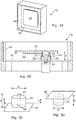
- FIG. 3A illustrates a perspective view of an example of the antenna system 10 illustrated in FIG. 2 and FIG 3B illustrates a cross section through the feed element 42, the first conductive element 22, the second conductive element 32, the antenna radiator 20 and the ground plane 30 of the antenna system 10 illustrated in FIG 3A .
- the first conductive element 22 is a hollow cylinder and the second conductive element 32 is a hollow cylinder.
- the diameter d 1 of the cylindrical first conductive element 22 is, in this example, smaller than the diameter d 2 of the cylindrical second conductive element 32.
- the cylindrical first conductive element 22 and the cylindrical second conductive element 32 are coaxial and they share the same axis with the feed element 42, as previously described. In this example, the cylindrical first conductive element 22 and the cylindrical second conductive element 32 overlap.
- the cylindrical first conductive element 22 is partially inserted inside the cylindrical second conductive element 32. As a consequence the first conductive element 22 is closer to the feed element 42 than the second conductive element 32.
- the second conductive element 32 is closer to the feed element 42 than the first conductive element 22.
- the diameter d 1 of the cylindrical first conductive element 22 is larger than the diameter d 2 of the cylindrical second conductive element 32.
- the ground plane 30 extends substantially in a first physical plane and the antenna radiator 20 extends substantially in a second physical plane parallel to the first physical plane.
- the first conductive element 22 extends substantially perpendicular to the first and second physical planes.
- the second conductive element 32 extends substantially perpendicular to the first and second physical planes.
- the feed element 42 extends substantially perpendicular to the first and second physical planes.
- FIG. 3C and FIG. 3D illustrate component parts of the antenna system 10 illustrated in FIG 3B.
- Fig 3C illustrates the ground plane 30 and the cylindrical second conductive element 32 that extend the ground plane 30 towards the antenna radiator 20. It also illustrates the feed element 42 extending through, but not contacting, the ground plane 30 towards the antenna radiator 20.
- the feed element 42 has a substantially cylindrical shape and the axis of the cylindrical feed element 42 and the axis of the cylindrical second conductive element 32 are aligned.
- Fig. 3D illustrates a portion of the antenna radiator 20 and also the cylindrical first conductive element 22 that extends the antenna radiator 20 towards the ground plane 30.
- the cylindrical first conductive element 22 has a diameter d 1 and the cylindrical second conductive element 32 as a diameter of d 2 .
- the diameter d 1 is less than the diameter d 2 .
- the cylindrical first conductive element 22 has a length l 1 and the cylindrical second conductive element 32 has a length l 2 .
- the antenna radiator 20 is separated from the ground plane 30 by a distance h where h is less than the sum of l 1 and l 2 . Consequently, the cylindrical first conductive element 22 and the cylindrical second conductive element 32 at least partially overlap. It can also be seen that in this example the length I of the feed element 42 above the ground plane 30 is greater than the length l 2 of the cylindrical second conductive element 32.
- the antenna system 10 as described in FIGS. 1, 2 , 3A and 3B is a volumetric antenna system that occupies a space 50.
- the space 50 is an open cavity defined by the ground plane 30 and side walls 34.
- a cavity 50 is open in the sense that it does not fully enclose the feed element 42 and/or the antenna radiator 20. There are for example gaps between the antenna radiator 20 and the side walls 34.
- side walls 34 are illustrated in these examples, they are entirely optional and in some examples they may be absent.
- the ground plane 30 is a conductive element of sufficient size that it can provide the function of a ground plane to the antenna system.
- a ground plane denotes a conductive element that provides a local ground or earth to a system.
- the ground plane is planar, the term "ground plane" should be understood in the functional rather than the physical sense. Therefore although in some examples the ground plane 30 is substantially physically planar in other examples it may not be.
- the ground plane 30 may be provided as a conductive layer of a printed circuit board (PCB) or as any other suitable conductor.
- the ground plane 30 can be provided by a conductive/metal enclosure or box which is either milled from solid metal or manufactured from sheet metal materials and any seams filled with conductive material (solder or other options) to adjoin adjacent walls or parts of the sheet material.
- the feed element 42 is an open-ended feed 40 configured to contactlessly feed the antenna radiator 20.
- the feed element 42 does not have a galvanic connection (direct current connection) to the antenna radiator 20. It extends through an aperture 60 in the ground plane 30, without making a galvanic connection to the ground plane 30, towards the antenna radiator 20.
- the radiator element 20 is, in the examples illustrated, a wideband radiator element. In the examples illustrated it is configured as a patch antenna but other antennas can be used.
- the radiator element 20, can in some examples be a narrowband radiator element.
- the radiator element 20 can be a different type of antenna, and examples include (without limitation) a PIFA (planar inverted-F antenna), a PILA (planar inverted-L antenna), a monopole, a dipole, a loop antenna, etc.
- the preceding examples illustrate a radio frequency feed 40 for the radiator element 20 that comprises the feed element 42, the first conductive element 22 and, optionally, the second conductive element 32.
- the combination of the first conductive element 22, the feed element 42 and, optionally, the conductive element 32 creates a narrowband resonant frequency feed 40 for the antenna radiator 20.
- the characteristics of the resonant circuit are such that it has a narrowband resonant frequency and has the inherent properties of a filter.
- the antenna system 10 can, in some examples comprise an antenna 20 fed by the narrowband resonant circuit.
- the antenna radiator 20 and the resonant feed operate two distinct resonant phenomena that overlap in frequency
- the resonant circuit has one or more resonant frequencies that are narrowband.
- the bandwidth of a resonant frequency is often described using a Q-factor.
- the resonant circuit defined by the feed element 42, the first conductive element 22 and, if present, the second conductive element 32 can be modelled as a complex RLC resonant circuit then the Q-factor can, in some circumstances be dependent upon 1/R*(L/C) 1/2 and the resonant frequency as (1/LC) 1/2 .
- the inductance L, the capacitance C and, optionally the resistance R it is possible to control the Q-factor and the resonant frequency of the feed 40.
- the inductance L can for example be controlled by varying the length and/or diameter of the feed element 42, the first conductive element 22 and, if present, the second conductive element 32. If a conductor is made longer and thinner then it will generally have a higher inductance.
- the capacitance C can for example be controlled by controlling the size of the gap between, the area of overlap between, the dielectric material between respective ones of the feed element 42, the first conductive element 22 and, if present, the second conductive element 32. Increasing the permittivity of the dielectric material, increasing the overlap and decreasing the gap will increase capacitance C.
- the capacitance between feed element 42 and the first conductive element 22 may be of a similar order of magnitude or similar value to the capacitance between the first conductive element 22 and the second conductive element 32.
- the antenna system 10 may be configured so that any one or more of the dimensions of feed element 42, the first conductive element 22 and, if present, the second conductive element 32 can be varied to tune the bandwidth of a resonant frequency of the feed 40 and/or tune a resonant frequency of the feed 40 and also, as a consequence, of the antenna system 10 . It will therefore be appreciated that it is possible to have an antenna system 10 that has the same physical size but which operates at different frequencies and/or with different Q-factors. This therefore enables the combination of a wideband antenna radiator 20 with different narrowband resonant frequency feeds 40.
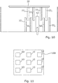
- FIGS. 4A , 4B and 4C illustrate the effects of changing some of the dimensions of one or more of the first conductive element 22, the feed element 42 and, if present, the second conductive element 32.
- the length l 2 of the cylindrical second conductive element 32 is fixed and the length l 1 of the cylindrical first conductive element 22 is varied. Varying the length of the inner cylindrical first conductive element 22 will vary capacitance and inductance. It can be seen from the FIG 4A that as the length l 1 of the cylindrical first conductive element 22 is increased the resonant frequency decreases.
- FIG. 4B illustrates the effect of varying the length I of the feed element 42.
- the Q-factor decreases causing a broadening of the resonant frequency band.
- FIG. 4C illustrates the effect of changing the diameter d 1 of the cylindrical first conductive element 22 while simultaneously changing the diameter d 2 of the cylindrical second conductive element 32 so that the gap between the first and second elements 22, 32 remains a constant. It can be seen from the figure that increasing the diameter decreases the Q-factor. This can for example be explained by a decrease in inductance when increasing the diameter d 1 .
- a feed 40 for an antenna radiator 20 comprising: a ground plane 30; a feed element 42 extending in a first direction from the ground plane 30 (e.g. optionally extending through an aperture 60 in the ground plane) and configured to provide a radio frequency feed 40 for the antenna radiator 20; a conductive element 32 extending in the first direction from the ground plane 30 and circumscribing at least a portion of a length of the feed element 42, wherein the feed element 42 is spatially separated from the conductive element 32 and the conductive element 32 is galvanically connected to the ground plane 20.
- the feed system 40 can, for example, be a narrowband resonant frequency feed as described above.
- FIG. 5 illustrates a view of an example of an antenna system 10 as previously described that illustrates a location L n of the feed 40 n relative to the antenna radiator 20.
- the feed 40 n comprises the feed element 42 n , the first conductive element 22 n and, if present, the second conductive element 32 n .
- the feed 40 n is positioned off center with respect to the antenna radiator 20 Closer to an edge of the antenna radiator 20 than a center of the antenna radiator 20.
- the feed 40 n is positioned along a diagonal of a rectangular or square patch antenna radiator towards a corner of the antenna radiator 20.
- the antenna system 10 can comprise a ground plane 30; a substantially planar antenna radiator 20 separated from and overlapping the ground plane 30; a first conductive element 22 1 extending, at a first location L1, the antenna radiator 20 towards the ground plane 30; a feed element 42 1 configured to provide a radio frequency feed 40 1 , at the first location L1, for the antenna radiator 20, wherein the feed element 42 1 is spatially separated from the first conductive element 22 1 and the antenna radiator 20; a further first conductive element 22 2 extending, at a second location L2, the antenna radiator 20 towards the ground plane 30; a further feed element 42 2 configured to provide a further radio frequency feed 40 2 , at the second location L2, for the antenna radiator 20, wherein the further feed element 42 2 is spatially separated from the further first conductive element 22 2 and the antenna radiator 20.
- a second conductive element 32 1 extending, at the first location L1, the ground plane 30 towards the antenna radiator 20, wherein the second conductive element 32 1 is spatially separated from the first conductive element 22 1 .
- a second conductive element 32 2 extending, at the second location L2, the ground plane 30 towards the antenna radiator 20, wherein the second conductive element 32 2 is spatially separated from the first conductive element 22 2 .
- the first conductive element 22 1 , the feed element 42 1 and, if present, the second conductive element 32 1 provide a first narrowband resonant frequency feed 40 1 .
- the further first conductive element 22 2 and the further feed element 42 2 and, if present, the further second conductive element 32 2 provide a further second narrowband resonance frequency feed 40 2 .
- the first narrowband resonant frequency feed 40 1 and the second narrowband resonant frequency feed 40 2 are configured to have different narrowband resonant frequencies, for example, as described above.
- the first narrowband resonant frequency feed 40 1 and the second narrowband resonant frequency feed 40 2 are configured to have the same resonant frequency but are located to have orthogonal polarization.
- FIG 6 illustrates an example of the antenna system 10 illustrated in FIG 5 where a wall 80 is used to physically separate the first narrowband resonant frequency feed 40 1 and the second narrowband resonant frequency feed 40 2
- FIG. 7 illustrates an example of previously described antenna systems 10. This example is similar to the example illustrated in FIGS. 3A, 3B, 3C and 3D . The description of those figures is also relevant to this figure.
- a dielectric material 70 placed between the cylindrical first conductive element 22 and the cylindrical second conductive element 32. This dielectric material 70 can be used to control a capacitance between the first conductive element 22 and the second conductive element 32 and can also be used to provide some physical support for the antenna radiator 20.
- the dielectric mount 72 may also be provided a dielectric mount 72 that is used to physically support the antenna radiator 20.
- the dielectric mount 72 comprises a notch into which a portion of the antenna radiator 20 is inserted.
- FIGS. 8A and 8B illustrate that it is possible to have different positions and arrangements for the feed element 42.
- the feed element 42 is closest to the exterior cylindrical second conductive element 32 rather than the interior cylindrical first conductive element 22.
- the feed element 42 is galvanically connected to the second conductive element 32.
- the feed element 42 is capacitively coupled to the second conductive element 32.
- FIG. 9 illustrates an example in which dielectric material 70 is placed within the cylindrical second conductive element 70 and surrounds the feed element 42.
- the dielectric material 70 provides a physical support for the antenna radiator 20.
- dielectric material 70 fills the void between the feed element 42 and the second conductive element 32. In this example, but not necessarily all examples, the dielectric material 70 fills the void between the first conductive element 22 and the second conductive element 32. In other examples, dielectric material 70 can additionally, or alternatively, fill the void between the feed element 42 and the first conductive element 22 or the void within the first conductive element 22.
- Dielectric material 70 can also be used in other examples, for example FIG 8A or 8B .
- dielectric material (not illustrated) can be placed between the outer conductive element 32 and the feed element 42.
- the feed element 42 could be manufactured as part of the conductive element 32 (and optionally also with the ground plane 30).
- MID Molded Interconnect Device
- LDS Laser Direct Structuring
- the dielectric 70 can serve two purposes- mechanical support and controlling the electrical resonant properties of the feed element 42 and/or the conductive elements 22, 32.
- FIG. 10 illustrates that although in the previous examples a single first conductive element 22 is used and a single second conductive element 32 is used it is possible to use additional conductive elements.
- the feed element 42 partially extends within a smaller diameter cylindrical first conductive element 22 1
- the smaller diameter cylindrical first conductive element 22 1 extends partially within a smaller diameter second cylindrical conductive element 32 1
- the smaller diameter cylindrical second conductive element 32 1 extends partially within a larger diameter cylindrical first conductive element 22 2
- the larger diameter cylindrical first conductive element 22 2 extends partially within a larger diameter cylindrical second conductive element 32 2 .
- the smaller diameter cylindrical first conductive element 22 1 and the larger diameter cylindrical first conductive element 22 2 both extend the antenna radiator 20 towards the ground plane 30 and in addition, are coaxial with an elongate axis of the feed element 42.
- the smaller diameter cylindrical second conductive element 32 1 and the larger diameter cylindrical second conductive element 32 2 both extend the ground plane 30 towards the antenna radiator 20 and in addition, are coaxial with an elongate axis of the feed element 42.
- first conductive element 22 and the second conductive element 32 are also relevant to the smaller diameter cylindrical first conductive element 22 1 and the smaller diameter second cylindrical conductive element 32 1 .
- first conductive element 22 and the second conductive element 32 are also relevant to the larger diameter cylindrical first conductive element 22 2 and the larger diameter second cylindrical conductive element 32 2 .
- FIG. 11 illustrates an example of a network access node 100 comprising one or more antenna systems 10 as previously described.
- the network access node 100 can for example be a radio access network (RAN) node, for example a base transceiver station.
- RAN radio access network
- the network access node 100 can for example be a user equipment node or a portable electronic device.
- the network access node 100 can, for example, be configured to transmit (but not receive), receive (but not transmit) or both transmit and receive. Having additional filtering within the antenna feed 40, as described above, can save space and components.
- the radio access technology can, for example, be 5G New Radio and/or 4G Long Term Evolution.
- the radio access technology can, for example, operate in the sub 6 GHz range or in the mm-wavelength frequency spectrum.
- the network access node 100 can for example comprise an antenna system 10 or a multiple antenna array formed from the multiple antenna systems 10.
- the narrowband radio frequency fed antenna systems 10 are particularly useful as the network access node 100 does not necessarily need to comprise large high -quality filters in addition to the antenna systems 10.
- MIMO multiple input multiple output
- Massive MIMO or mMIMO multiple input multiple output
- An operational resonant mode is a frequency range over which an antenna can efficiently operate.
- An operational resonant mode may be defined as where the return loss S11 of the antenna 20 is less than a (negative) operational threshold T.
- the S11 of the antenna varies for different systems, mostly depending on the frequency range and the power. For example, 10-14 dB return loss is acceptable-according to some specifications for a base station.
- Narrowband could for example be 100- 200 MHz at 3.5 GHz,. Wideband could be more than double, e.g. 400 MHz.
- the instantaneous bandwidth for a 5G antenna is 100 MHz, the range of operation is currently 200 MHz (3.5 GHz - 3.7 GHz) and can at any moment extend to 400 MHz (e.g. 3.3 GHz - 3.7 GHz). So 100 MHz can, in this example, be considered narrowband and the 400 MHz can be considered wideband. For other antenna applications these number vary.
- the antenna radiator 20 and the feed 40 may be configured to operate in a plurality of operational resonant frequency bands.
- the operational frequency bands may include (but are not limited to) Long Term Evolution (LTE) (US) (734 to 746 MHz and 869 to 894 MHz), Long Term Evolution (LTE) (rest of the world) (791 to 821 MHz and 925 to 960 MHz), amplitude modulation (AM) radio (0.535-1.705 MHz); frequency modulation (FM) radio (76-108 MHz); Bluetooth (2400-2483.5 MHz); wireless local area network (WLAN) (2400-2483.5 MHz); hiper local area network (HiperLAN) (5150-5850 MHz); global positioning system (GPS) (1570.42-1580.42 MHz); US - Global system for mobile communications (US-GSM) 850 (824-894 MHz) and 1900 (1850 - 1990 MHz); European global system for mobile communications (EGSM) 900 (880-960 MHz) and 1800 (1710 - 1880 MHz);
- the antenna radiator may only partially overlap the ground plane 30.
- a circular cut-out can be used to create an aperture 60 for the feed element 42 to extend through.
- the above described examples find application as enabling components of: automotive systems; telecommunication systems; electronic systems including consumer electronic products; distributed computing systems; media systems for generating or rendering media content including audio, visual and audio visual content and mixed, mediated, virtual and/or augmented reality; personal systems including personal health systems or personal fitness systems; navigation systems; user interfaces also known as human machine interfaces; networks including cellular, non-cellular, and optical networks; ad-hoc networks; the internet; the internet of things; virtualized networks; and related software and services.
- a property of the instance can be a property of only that instance or a property of the class or a property of a sub-class of the class that includes some but not all of the instances in the class. It is therefore implicitly disclosed that a feature described with reference to one example but not with reference to another example, can where possible be used in that other example as part of a working combination but does not necessarily have to be used in that other example.
- 'a' or 'the' is used in this document with an inclusive not an exclusive meaning. That is any reference to X comprising a/the Y indicates that X may comprise only one Y or may comprise more than one Y unless the context clearly indicates the contrary. If it is intended to use 'a' or 'the' with an exclusive meaning then it will be made clear in the context. In some circumstances the use of 'at least one' or 'one or more' may be used to emphasis an inclusive meaning but the absence of these terms should not be taken to infer any exclusive meaning.
- the presence of a feature (or combination of features) in a claim is a reference to that feature or (combination of features) itself and also to features that achieve substantially the same technical effect (equivalent features).
- the equivalent features include, for example, features that are variants and achieve substantially the same result in substantially the same way.
- the equivalent features include, for example, features that perform substantially the same function, in substantially the same way to achieve substantially the same result.
Landscapes
- Physics & Mathematics (AREA)
- Electromagnetism (AREA)
- Engineering & Computer Science (AREA)
- Computer Networks & Wireless Communication (AREA)
- Details Of Aerials (AREA)
- Waveguide Aerials (AREA)
Priority Applications (3)
| Application Number | Priority Date | Filing Date | Title |
|---|---|---|---|
| EP20153977.2A EP3859893B1 (de) | 2020-01-28 | 2020-01-28 | Antennensystem |
| US17/158,135 US11527830B2 (en) | 2020-01-28 | 2021-01-26 | Antenna system with radiator extensions |
| CN202110109152.5A CN113258283B (zh) | 2020-01-28 | 2021-01-27 | 天线系统 |
Applications Claiming Priority (1)
| Application Number | Priority Date | Filing Date | Title |
|---|---|---|---|
| EP20153977.2A EP3859893B1 (de) | 2020-01-28 | 2020-01-28 | Antennensystem |
Publications (2)
| Publication Number | Publication Date |
|---|---|
| EP3859893A1 true EP3859893A1 (de) | 2021-08-04 |
| EP3859893B1 EP3859893B1 (de) | 2023-08-09 |
Family
ID=69374164
Family Applications (1)
| Application Number | Title | Priority Date | Filing Date |
|---|---|---|---|
| EP20153977.2A Active EP3859893B1 (de) | 2020-01-28 | 2020-01-28 | Antennensystem |
Country Status (3)
| Country | Link |
|---|---|
| US (1) | US11527830B2 (de) |
| EP (1) | EP3859893B1 (de) |
| CN (1) | CN113258283B (de) |
Families Citing this family (1)
| Publication number | Priority date | Publication date | Assignee | Title |
|---|---|---|---|---|
| CN114665345B (zh) * | 2022-03-30 | 2023-11-07 | 中国电子科技集团公司第十研究所 | 一种耦合式射频连接器 |
Citations (6)
| Publication number | Priority date | Publication date | Assignee | Title |
|---|---|---|---|---|
| US20040160380A1 (en) * | 2003-02-14 | 2004-08-19 | Simpson Robert G. | Compact monopole antenna with improved bandwidth |
| US20070268188A1 (en) * | 2006-04-26 | 2007-11-22 | Spotwave Wireless Canada, Inc. | Ground plane patch antenna |
| US20090140930A1 (en) * | 2007-11-29 | 2009-06-04 | Topcon Gps, Llc | Patch Antenna with Capacitive Elements |
| US20120068902A1 (en) * | 2009-06-09 | 2012-03-22 | The Secretary Of State For Defence | Electrically small ultra-wideband antenna for mobile handsets and computer networks |
| KR101974546B1 (ko) * | 2019-01-18 | 2019-05-02 | 한화시스템 주식회사 | 필터 내장형 캐비티 백 안테나 |
| US20190198998A1 (en) * | 2017-12-21 | 2019-06-27 | The Hong Kong University Of Science And Technology | Compact integrated three-broadside-mode patch antenna |
Family Cites Families (22)
| Publication number | Priority date | Publication date | Assignee | Title |
|---|---|---|---|---|
| US4763130A (en) * | 1987-05-11 | 1988-08-09 | General Instrument Corporation | Probe-fed slot antenna with coupling ring |
| US4924236A (en) * | 1987-11-03 | 1990-05-08 | Raytheon Company | Patch radiator element with microstrip balian circuit providing double-tuned impedance matching |
| NZ506062A (en) | 2000-07-31 | 2002-12-20 | Andrew Corp | Dual polarisation patch antenna characterised by first and second pair of orthogonally disposed probes feeding a patch network wherein the first feed path feeds in two probes with one patch going through a stub element so as to cause cancellation of the first feed path |
| US6937202B2 (en) | 2003-05-20 | 2005-08-30 | Northrop Grumman Corporation | Broadband waveguide horn antenna and method of feeding an antenna structure |
| FR2869727B1 (fr) * | 2004-04-30 | 2007-04-06 | Get Enst Bretagne Etablissemen | Antenne planaire a plots conducteurs s'etendant a partir du plan de masse et/ou d'au moins un element rayonnant, et procede de fabrication correspondant |
| US7710324B2 (en) * | 2005-01-19 | 2010-05-04 | Topcon Gps, Llc | Patch antenna with comb substrate |
| CN101038983B (zh) | 2006-03-13 | 2012-09-05 | 中国科学院电子学研究所 | 用于宽频微带天线的可变频耦合馈电装置 |
| DE102006038528B3 (de) * | 2006-08-17 | 2007-11-22 | Kathrein-Werke Kg | Abstimmbare Antenne planarer Bauart |
| TWI462395B (zh) * | 2008-10-09 | 2014-11-21 | Wistron Neweb Corp | 攜帶式電子裝置及其內嵌式超寬頻天線 |
| CN102460832A (zh) * | 2009-06-09 | 2012-05-16 | 英国国防部 | 用于无线电波的发射和接收的小型超宽带天线 |
| US20130187726A1 (en) | 2011-06-28 | 2013-07-25 | John T. Apostolos | Tunable variable impedance transmission line |
| US9647328B2 (en) * | 2011-11-04 | 2017-05-09 | Kathrein-Werke Kg | Patch radiator |
| US8654034B2 (en) | 2012-01-24 | 2014-02-18 | The United States Of America As Represented By The Secretary Of The Air Force | Dynamically reconfigurable feed network for multi-element planar array antenna |
| US9673526B1 (en) * | 2014-03-12 | 2017-06-06 | First Rf Corporation | Dual-frequency stacked patch antenna |
| US9748654B2 (en) * | 2014-12-16 | 2017-08-29 | Laird Technologies, Inc. | Antenna systems with proximity coupled annular rectangular patches |
| WO2017148237A1 (zh) * | 2016-02-29 | 2017-09-08 | 华南理工大学 | 一种低剖面宽带高增益滤波天线 |
| US10014584B1 (en) * | 2016-07-08 | 2018-07-03 | The United States Of America As Represented By The Secretary Of The Navy | Slotted antenna with uniaxial dielectric covering |
| EP3331093A1 (de) * | 2016-12-01 | 2018-06-06 | Nokia Technologies Oy | Resonator und filter damit |
| EP3333967A1 (de) * | 2016-12-12 | 2018-06-13 | Nokia Technologies OY | Resonator |
| JP2021027527A (ja) * | 2019-08-07 | 2021-02-22 | 日立金属株式会社 | マルチバンドアンテナおよびマルチバンドアンテナの設計方法 |
| FR3108209B1 (fr) * | 2020-03-10 | 2022-02-25 | Commissariat Energie Atomique | Antenne fil-plaque monopolaire reconfigurable en fréquence |
| US11929556B2 (en) * | 2020-09-08 | 2024-03-12 | Raytheon Company | Multi-beam passively-switched patch antenna array |
-
2020
- 2020-01-28 EP EP20153977.2A patent/EP3859893B1/de active Active
-
2021
- 2021-01-26 US US17/158,135 patent/US11527830B2/en active Active
- 2021-01-27 CN CN202110109152.5A patent/CN113258283B/zh active Active
Patent Citations (6)
| Publication number | Priority date | Publication date | Assignee | Title |
|---|---|---|---|---|
| US20040160380A1 (en) * | 2003-02-14 | 2004-08-19 | Simpson Robert G. | Compact monopole antenna with improved bandwidth |
| US20070268188A1 (en) * | 2006-04-26 | 2007-11-22 | Spotwave Wireless Canada, Inc. | Ground plane patch antenna |
| US20090140930A1 (en) * | 2007-11-29 | 2009-06-04 | Topcon Gps, Llc | Patch Antenna with Capacitive Elements |
| US20120068902A1 (en) * | 2009-06-09 | 2012-03-22 | The Secretary Of State For Defence | Electrically small ultra-wideband antenna for mobile handsets and computer networks |
| US20190198998A1 (en) * | 2017-12-21 | 2019-06-27 | The Hong Kong University Of Science And Technology | Compact integrated three-broadside-mode patch antenna |
| KR101974546B1 (ko) * | 2019-01-18 | 2019-05-02 | 한화시스템 주식회사 | 필터 내장형 캐비티 백 안테나 |
Also Published As
| Publication number | Publication date |
|---|---|
| US11527830B2 (en) | 2022-12-13 |
| US20210234271A1 (en) | 2021-07-29 |
| CN113258283A (zh) | 2021-08-13 |
| EP3859893B1 (de) | 2023-08-09 |
| CN113258283B (zh) | 2024-08-16 |
Similar Documents
| Publication | Publication Date | Title |
|---|---|---|
| EP1790034B1 (de) | Antenneneinrichtung und tragbares funkkommunikationsgerät mit einer solchen antenneneinrichtung | |
| US8138981B2 (en) | Antenna set, portable wireless device, and use of a conductive element for tuning the ground-plane of the antenna set | |
| EP3734757B1 (de) | Mehrbandantennenanordnung | |
| EP3742552B1 (de) | Mehrbandantennenanordnung | |
| CN112689033B (zh) | 终端设备 | |
| WO2005099041A1 (en) | Multi-band compact pifa antenna with meandered slot(s) | |
| WO2019232673A1 (en) | A cavity filter | |
| WO2012025787A1 (en) | Apparatus and methods for wireless communication | |
| CN110854509B (zh) | 用于无线通信的装置 | |
| WO2001008257A1 (en) | Antenna arrangement | |
| GB2520228A (en) | Apparatus and methods for wireless communication | |
| US8289219B2 (en) | Antenna arrangement | |
| US11527830B2 (en) | Antenna system with radiator extensions | |
| CN115244780B (zh) | 天线布置 | |
| US12266872B2 (en) | Compact multi-band antenna | |
| CN113644447B (zh) | 天线装置 | |
| EP3791444B1 (de) | Antennenanordnung für drahtlose vorrichtung | |
| Luo et al. | Low cost compact multiband printed monopole antennas and arrays for wireless communications | |
| US9755315B2 (en) | Antenna arrangement |
Legal Events
| Date | Code | Title | Description |
|---|---|---|---|
| PUAI | Public reference made under article 153(3) epc to a published international application that has entered the european phase |
Free format text: ORIGINAL CODE: 0009012 |
|
| STAA | Information on the status of an ep patent application or granted ep patent |
Free format text: STATUS: THE APPLICATION HAS BEEN PUBLISHED |
|
| AK | Designated contracting states |
Kind code of ref document: A1 Designated state(s): AL AT BE BG CH CY CZ DE DK EE ES FI FR GB GR HR HU IE IS IT LI LT LU LV MC MK MT NL NO PL PT RO RS SE SI SK SM TR |
|
| STAA | Information on the status of an ep patent application or granted ep patent |
Free format text: STATUS: REQUEST FOR EXAMINATION WAS MADE |
|
| 17P | Request for examination filed |
Effective date: 20220202 |
|
| RBV | Designated contracting states (corrected) |
Designated state(s): AL AT BE BG CH CY CZ DE DK EE ES FI FR GB GR HR HU IE IS IT LI LT LU LV MC MK MT NL NO PL PT RO RS SE SI SK SM TR |
|
| GRAP | Despatch of communication of intention to grant a patent |
Free format text: ORIGINAL CODE: EPIDOSNIGR1 |
|
| STAA | Information on the status of an ep patent application or granted ep patent |
Free format text: STATUS: GRANT OF PATENT IS INTENDED |
|
| INTG | Intention to grant announced |
Effective date: 20230303 |
|
| GRAS | Grant fee paid |
Free format text: ORIGINAL CODE: EPIDOSNIGR3 |
|
| GRAA | (expected) grant |
Free format text: ORIGINAL CODE: 0009210 |
|
| STAA | Information on the status of an ep patent application or granted ep patent |
Free format text: STATUS: THE PATENT HAS BEEN GRANTED |
|
| AK | Designated contracting states |
Kind code of ref document: B1 Designated state(s): AL AT BE BG CH CY CZ DE DK EE ES FI FR GB GR HR HU IE IS IT LI LT LU LV MC MK MT NL NO PL PT RO RS SE SI SK SM TR |
|
| REG | Reference to a national code |
Ref country code: GB Ref legal event code: FG4D |
|
| REG | Reference to a national code |
Ref country code: CH Ref legal event code: EP |
|
| REG | Reference to a national code |
Ref country code: DE Ref legal event code: R096 Ref document number: 602020015201 Country of ref document: DE |
|
| REG | Reference to a national code |
Ref country code: IE Ref legal event code: FG4D |
|
| REG | Reference to a national code |
Ref country code: LT Ref legal event code: MG9D |
|
| REG | Reference to a national code |
Ref country code: NL Ref legal event code: MP Effective date: 20230809 |
|
| REG | Reference to a national code |
Ref country code: AT Ref legal event code: MK05 Ref document number: 1598604 Country of ref document: AT Kind code of ref document: T Effective date: 20230809 |
|
| PG25 | Lapsed in a contracting state [announced via postgrant information from national office to epo] |
Ref country code: GR Free format text: LAPSE BECAUSE OF FAILURE TO SUBMIT A TRANSLATION OF THE DESCRIPTION OR TO PAY THE FEE WITHIN THE PRESCRIBED TIME-LIMIT Effective date: 20231110 |
|
| PG25 | Lapsed in a contracting state [announced via postgrant information from national office to epo] |
Ref country code: IS Free format text: LAPSE BECAUSE OF FAILURE TO SUBMIT A TRANSLATION OF THE DESCRIPTION OR TO PAY THE FEE WITHIN THE PRESCRIBED TIME-LIMIT Effective date: 20231209 |
|
| PG25 | Lapsed in a contracting state [announced via postgrant information from national office to epo] |
Ref country code: SE Free format text: LAPSE BECAUSE OF FAILURE TO SUBMIT A TRANSLATION OF THE DESCRIPTION OR TO PAY THE FEE WITHIN THE PRESCRIBED TIME-LIMIT Effective date: 20230809 Ref country code: RS Free format text: LAPSE BECAUSE OF FAILURE TO SUBMIT A TRANSLATION OF THE DESCRIPTION OR TO PAY THE FEE WITHIN THE PRESCRIBED TIME-LIMIT Effective date: 20230809 Ref country code: PT Free format text: LAPSE BECAUSE OF FAILURE TO SUBMIT A TRANSLATION OF THE DESCRIPTION OR TO PAY THE FEE WITHIN THE PRESCRIBED TIME-LIMIT Effective date: 20231211 Ref country code: NO Free format text: LAPSE BECAUSE OF FAILURE TO SUBMIT A TRANSLATION OF THE DESCRIPTION OR TO PAY THE FEE WITHIN THE PRESCRIBED TIME-LIMIT Effective date: 20231109 Ref country code: NL Free format text: LAPSE BECAUSE OF FAILURE TO SUBMIT A TRANSLATION OF THE DESCRIPTION OR TO PAY THE FEE WITHIN THE PRESCRIBED TIME-LIMIT Effective date: 20230809 Ref country code: LV Free format text: LAPSE BECAUSE OF FAILURE TO SUBMIT A TRANSLATION OF THE DESCRIPTION OR TO PAY THE FEE WITHIN THE PRESCRIBED TIME-LIMIT Effective date: 20230809 Ref country code: LT Free format text: LAPSE BECAUSE OF FAILURE TO SUBMIT A TRANSLATION OF THE DESCRIPTION OR TO PAY THE FEE WITHIN THE PRESCRIBED TIME-LIMIT Effective date: 20230809 Ref country code: IS Free format text: LAPSE BECAUSE OF FAILURE TO SUBMIT A TRANSLATION OF THE DESCRIPTION OR TO PAY THE FEE WITHIN THE PRESCRIBED TIME-LIMIT Effective date: 20231209 Ref country code: HR Free format text: LAPSE BECAUSE OF FAILURE TO SUBMIT A TRANSLATION OF THE DESCRIPTION OR TO PAY THE FEE WITHIN THE PRESCRIBED TIME-LIMIT Effective date: 20230809 Ref country code: GR Free format text: LAPSE BECAUSE OF FAILURE TO SUBMIT A TRANSLATION OF THE DESCRIPTION OR TO PAY THE FEE WITHIN THE PRESCRIBED TIME-LIMIT Effective date: 20231110 Ref country code: FI Free format text: LAPSE BECAUSE OF FAILURE TO SUBMIT A TRANSLATION OF THE DESCRIPTION OR TO PAY THE FEE WITHIN THE PRESCRIBED TIME-LIMIT Effective date: 20230809 Ref country code: AT Free format text: LAPSE BECAUSE OF FAILURE TO SUBMIT A TRANSLATION OF THE DESCRIPTION OR TO PAY THE FEE WITHIN THE PRESCRIBED TIME-LIMIT Effective date: 20230809 |
|
| PG25 | Lapsed in a contracting state [announced via postgrant information from national office to epo] |
Ref country code: PL Free format text: LAPSE BECAUSE OF FAILURE TO SUBMIT A TRANSLATION OF THE DESCRIPTION OR TO PAY THE FEE WITHIN THE PRESCRIBED TIME-LIMIT Effective date: 20230809 |
|
| PG25 | Lapsed in a contracting state [announced via postgrant information from national office to epo] |
Ref country code: ES Free format text: LAPSE BECAUSE OF FAILURE TO SUBMIT A TRANSLATION OF THE DESCRIPTION OR TO PAY THE FEE WITHIN THE PRESCRIBED TIME-LIMIT Effective date: 20230809 |
|
| PG25 | Lapsed in a contracting state [announced via postgrant information from national office to epo] |
Ref country code: SM Free format text: LAPSE BECAUSE OF FAILURE TO SUBMIT A TRANSLATION OF THE DESCRIPTION OR TO PAY THE FEE WITHIN THE PRESCRIBED TIME-LIMIT Effective date: 20230809 Ref country code: RO Free format text: LAPSE BECAUSE OF FAILURE TO SUBMIT A TRANSLATION OF THE DESCRIPTION OR TO PAY THE FEE WITHIN THE PRESCRIBED TIME-LIMIT Effective date: 20230809 Ref country code: ES Free format text: LAPSE BECAUSE OF FAILURE TO SUBMIT A TRANSLATION OF THE DESCRIPTION OR TO PAY THE FEE WITHIN THE PRESCRIBED TIME-LIMIT Effective date: 20230809 Ref country code: EE Free format text: LAPSE BECAUSE OF FAILURE TO SUBMIT A TRANSLATION OF THE DESCRIPTION OR TO PAY THE FEE WITHIN THE PRESCRIBED TIME-LIMIT Effective date: 20230809 Ref country code: DK Free format text: LAPSE BECAUSE OF FAILURE TO SUBMIT A TRANSLATION OF THE DESCRIPTION OR TO PAY THE FEE WITHIN THE PRESCRIBED TIME-LIMIT Effective date: 20230809 Ref country code: CZ Free format text: LAPSE BECAUSE OF FAILURE TO SUBMIT A TRANSLATION OF THE DESCRIPTION OR TO PAY THE FEE WITHIN THE PRESCRIBED TIME-LIMIT Effective date: 20230809 Ref country code: SK Free format text: LAPSE BECAUSE OF FAILURE TO SUBMIT A TRANSLATION OF THE DESCRIPTION OR TO PAY THE FEE WITHIN THE PRESCRIBED TIME-LIMIT Effective date: 20230809 |
|
| REG | Reference to a national code |
Ref country code: DE Ref legal event code: R097 Ref document number: 602020015201 Country of ref document: DE |
|
| PG25 | Lapsed in a contracting state [announced via postgrant information from national office to epo] |
Ref country code: IT Free format text: LAPSE BECAUSE OF FAILURE TO SUBMIT A TRANSLATION OF THE DESCRIPTION OR TO PAY THE FEE WITHIN THE PRESCRIBED TIME-LIMIT Effective date: 20230809 |
|
| PLBE | No opposition filed within time limit |
Free format text: ORIGINAL CODE: 0009261 |
|
| STAA | Information on the status of an ep patent application or granted ep patent |
Free format text: STATUS: NO OPPOSITION FILED WITHIN TIME LIMIT |
|
| 26N | No opposition filed |
Effective date: 20240513 |
|
| PG25 | Lapsed in a contracting state [announced via postgrant information from national office to epo] |
Ref country code: SI Free format text: LAPSE BECAUSE OF FAILURE TO SUBMIT A TRANSLATION OF THE DESCRIPTION OR TO PAY THE FEE WITHIN THE PRESCRIBED TIME-LIMIT Effective date: 20230809 |
|
| PG25 | Lapsed in a contracting state [announced via postgrant information from national office to epo] |
Ref country code: MC Free format text: LAPSE BECAUSE OF FAILURE TO SUBMIT A TRANSLATION OF THE DESCRIPTION OR TO PAY THE FEE WITHIN THE PRESCRIBED TIME-LIMIT Effective date: 20230809 |
|
| PG25 | Lapsed in a contracting state [announced via postgrant information from national office to epo] |
Ref country code: MC Free format text: LAPSE BECAUSE OF FAILURE TO SUBMIT A TRANSLATION OF THE DESCRIPTION OR TO PAY THE FEE WITHIN THE PRESCRIBED TIME-LIMIT Effective date: 20230809 |
|
| REG | Reference to a national code |
Ref country code: CH Ref legal event code: PL |
|
| PG25 | Lapsed in a contracting state [announced via postgrant information from national office to epo] |
Ref country code: LU Free format text: LAPSE BECAUSE OF NON-PAYMENT OF DUE FEES Effective date: 20240128 |
|
| PG25 | Lapsed in a contracting state [announced via postgrant information from national office to epo] |
Ref country code: LU Free format text: LAPSE BECAUSE OF NON-PAYMENT OF DUE FEES Effective date: 20240128 |
|
| PG25 | Lapsed in a contracting state [announced via postgrant information from national office to epo] |
Ref country code: BE Free format text: LAPSE BECAUSE OF NON-PAYMENT OF DUE FEES Effective date: 20240131 |
|
| PG25 | Lapsed in a contracting state [announced via postgrant information from national office to epo] |
Ref country code: CH Free format text: LAPSE BECAUSE OF NON-PAYMENT OF DUE FEES Effective date: 20240131 |
|
| PG25 | Lapsed in a contracting state [announced via postgrant information from national office to epo] |
Ref country code: CH Free format text: LAPSE BECAUSE OF NON-PAYMENT OF DUE FEES Effective date: 20240131 Ref country code: BE Free format text: LAPSE BECAUSE OF NON-PAYMENT OF DUE FEES Effective date: 20240131 |
|
| REG | Reference to a national code |
Ref country code: BE Ref legal event code: MM Effective date: 20240131 |
|
| PG25 | Lapsed in a contracting state [announced via postgrant information from national office to epo] |
Ref country code: BG Free format text: LAPSE BECAUSE OF FAILURE TO SUBMIT A TRANSLATION OF THE DESCRIPTION OR TO PAY THE FEE WITHIN THE PRESCRIBED TIME-LIMIT Effective date: 20230809 |
|
| PG25 | Lapsed in a contracting state [announced via postgrant information from national office to epo] |
Ref country code: BG Free format text: LAPSE BECAUSE OF FAILURE TO SUBMIT A TRANSLATION OF THE DESCRIPTION OR TO PAY THE FEE WITHIN THE PRESCRIBED TIME-LIMIT Effective date: 20230809 |
|
| PG25 | Lapsed in a contracting state [announced via postgrant information from national office to epo] |
Ref country code: IE Free format text: LAPSE BECAUSE OF NON-PAYMENT OF DUE FEES Effective date: 20240128 |
|
| PG25 | Lapsed in a contracting state [announced via postgrant information from national office to epo] |
Ref country code: IE Free format text: LAPSE BECAUSE OF NON-PAYMENT OF DUE FEES Effective date: 20240128 |
|
| PG25 | Lapsed in a contracting state [announced via postgrant information from national office to epo] |
Ref country code: CY Free format text: LAPSE BECAUSE OF FAILURE TO SUBMIT A TRANSLATION OF THE DESCRIPTION OR TO PAY THE FEE WITHIN THE PRESCRIBED TIME-LIMIT; INVALID AB INITIO Effective date: 20200128 |
|
| PG25 | Lapsed in a contracting state [announced via postgrant information from national office to epo] |
Ref country code: HU Free format text: LAPSE BECAUSE OF FAILURE TO SUBMIT A TRANSLATION OF THE DESCRIPTION OR TO PAY THE FEE WITHIN THE PRESCRIBED TIME-LIMIT; INVALID AB INITIO Effective date: 20200128 |
|
| PG25 | Lapsed in a contracting state [announced via postgrant information from national office to epo] |
Ref country code: TR Free format text: LAPSE BECAUSE OF FAILURE TO SUBMIT A TRANSLATION OF THE DESCRIPTION OR TO PAY THE FEE WITHIN THE PRESCRIBED TIME-LIMIT Effective date: 20230809 |
|
| PGFP | Annual fee paid to national office [announced via postgrant information from national office to epo] |
Ref country code: GB Payment date: 20251204 Year of fee payment: 7 |
|
| PGFP | Annual fee paid to national office [announced via postgrant information from national office to epo] |
Ref country code: FR Payment date: 20251208 Year of fee payment: 7 |
|
| PGFP | Annual fee paid to national office [announced via postgrant information from national office to epo] |
Ref country code: DE Payment date: 20251203 Year of fee payment: 7 |