EP3859925B1 - Anordnung, fahrzeug und verfahren - Google Patents
Anordnung, fahrzeug und verfahren Download PDFInfo
- Publication number
- EP3859925B1 EP3859925B1 EP20154047.3A EP20154047A EP3859925B1 EP 3859925 B1 EP3859925 B1 EP 3859925B1 EP 20154047 A EP20154047 A EP 20154047A EP 3859925 B1 EP3859925 B1 EP 3859925B1
- Authority
- EP
- European Patent Office
- Prior art keywords
- cable
- arrangement
- control arm
- contacting surfaces
- triangle
- Prior art date
- Legal status (The legal status is an assumption and is not a legal conclusion. Google has not performed a legal analysis and makes no representation as to the accuracy of the status listed.)
- Active
Links
Images


Classifications
-
- B—PERFORMING OPERATIONS; TRANSPORTING
- B60—VEHICLES IN GENERAL
- B60L—PROPULSION OF ELECTRICALLY-PROPELLED VEHICLES; SUPPLYING ELECTRIC POWER FOR AUXILIARY EQUIPMENT OF ELECTRICALLY-PROPELLED VEHICLES; ELECTRODYNAMIC BRAKE SYSTEMS FOR VEHICLES IN GENERAL; MAGNETIC SUSPENSION OR LEVITATION FOR VEHICLES; MONITORING OPERATING VARIABLES OF ELECTRICALLY-PROPELLED VEHICLES; ELECTRIC SAFETY DEVICES FOR ELECTRICALLY-PROPELLED VEHICLES
- B60L5/00—Current collectors for power supply lines of electrically-propelled vehicles
-
- B—PERFORMING OPERATIONS; TRANSPORTING
- B60—VEHICLES IN GENERAL
- B60L—PROPULSION OF ELECTRICALLY-PROPELLED VEHICLES; SUPPLYING ELECTRIC POWER FOR AUXILIARY EQUIPMENT OF ELECTRICALLY-PROPELLED VEHICLES; ELECTRODYNAMIC BRAKE SYSTEMS FOR VEHICLES IN GENERAL; MAGNETIC SUSPENSION OR LEVITATION FOR VEHICLES; MONITORING OPERATING VARIABLES OF ELECTRICALLY-PROPELLED VEHICLES; ELECTRIC SAFETY DEVICES FOR ELECTRICALLY-PROPELLED VEHICLES
- B60L9/00—Electric propulsion with power supply external to the vehicle
-
- B—PERFORMING OPERATIONS; TRANSPORTING
- B65—CONVEYING; PACKING; STORING; HANDLING THIN OR FILAMENTARY MATERIAL
- B65H—HANDLING THIN OR FILAMENTARY MATERIAL, e.g. SHEETS, WEBS, CABLES
- B65H59/00—Adjusting or controlling tension in filamentary material, e.g. for preventing snarling; Applications of tension indicators
- B65H59/38—Adjusting or controlling tension in filamentary material, e.g. for preventing snarling; Applications of tension indicators by regulating speed of driving mechanism of unwinding, paying-out, forwarding, winding, or depositing devices, e.g. automatically in response to variations in tension
- B65H59/384—Adjusting or controlling tension in filamentary material, e.g. for preventing snarling; Applications of tension indicators by regulating speed of driving mechanism of unwinding, paying-out, forwarding, winding, or depositing devices, e.g. automatically in response to variations in tension using electronic means
-
- B—PERFORMING OPERATIONS; TRANSPORTING
- B65—CONVEYING; PACKING; STORING; HANDLING THIN OR FILAMENTARY MATERIAL
- B65H—HANDLING THIN OR FILAMENTARY MATERIAL, e.g. SHEETS, WEBS, CABLES
- B65H75/00—Storing webs, tapes, or filamentary material, e.g. on reels
- B65H75/02—Cores, formers, supports, or holders for coiled, wound, or folded material, e.g. reels, spindles, bobbins, cop tubes, cans, mandrels or chucks
- B65H75/34—Cores, formers, supports, or holders for coiled, wound, or folded material, e.g. reels, spindles, bobbins, cop tubes, cans, mandrels or chucks specially adapted or mounted for storing and repeatedly paying-out and re-storing lengths of material provided for particular purposes, e.g. anchored hoses, power cables
- B65H75/38—Cores, formers, supports, or holders for coiled, wound, or folded material, e.g. reels, spindles, bobbins, cop tubes, cans, mandrels or chucks specially adapted or mounted for storing and repeatedly paying-out and re-storing lengths of material provided for particular purposes, e.g. anchored hoses, power cables involving the use of a core or former internal to, and supporting, a stored package of material
- B65H75/40—Cores, formers, supports, or holders for coiled, wound, or folded material, e.g. reels, spindles, bobbins, cop tubes, cans, mandrels or chucks specially adapted or mounted for storing and repeatedly paying-out and re-storing lengths of material provided for particular purposes, e.g. anchored hoses, power cables involving the use of a core or former internal to, and supporting, a stored package of material mobile or transportable
- B65H75/42—Cores, formers, supports, or holders for coiled, wound, or folded material, e.g. reels, spindles, bobbins, cop tubes, cans, mandrels or chucks specially adapted or mounted for storing and repeatedly paying-out and re-storing lengths of material provided for particular purposes, e.g. anchored hoses, power cables involving the use of a core or former internal to, and supporting, a stored package of material mobile or transportable attached to, or forming part of, mobile tools, machines or vehicles
- B65H75/425—Cores, formers, supports, or holders for coiled, wound, or folded material, e.g. reels, spindles, bobbins, cop tubes, cans, mandrels or chucks specially adapted or mounted for storing and repeatedly paying-out and re-storing lengths of material provided for particular purposes, e.g. anchored hoses, power cables involving the use of a core or former internal to, and supporting, a stored package of material mobile or transportable attached to, or forming part of, mobile tools, machines or vehicles attached to, or forming part of a vehicle, e.g. truck, trailer, vessel
-
- B—PERFORMING OPERATIONS; TRANSPORTING
- B65—CONVEYING; PACKING; STORING; HANDLING THIN OR FILAMENTARY MATERIAL
- B65H—HANDLING THIN OR FILAMENTARY MATERIAL, e.g. SHEETS, WEBS, CABLES
- B65H75/00—Storing webs, tapes, or filamentary material, e.g. on reels
- B65H75/02—Cores, formers, supports, or holders for coiled, wound, or folded material, e.g. reels, spindles, bobbins, cop tubes, cans, mandrels or chucks
- B65H75/34—Cores, formers, supports, or holders for coiled, wound, or folded material, e.g. reels, spindles, bobbins, cop tubes, cans, mandrels or chucks specially adapted or mounted for storing and repeatedly paying-out and re-storing lengths of material provided for particular purposes, e.g. anchored hoses, power cables
- B65H75/38—Cores, formers, supports, or holders for coiled, wound, or folded material, e.g. reels, spindles, bobbins, cop tubes, cans, mandrels or chucks specially adapted or mounted for storing and repeatedly paying-out and re-storing lengths of material provided for particular purposes, e.g. anchored hoses, power cables involving the use of a core or former internal to, and supporting, a stored package of material
- B65H75/44—Constructional details
- B65H75/4402—Guiding arrangements to control paying-out and re-storing of the material
-
- B—PERFORMING OPERATIONS; TRANSPORTING
- B65—CONVEYING; PACKING; STORING; HANDLING THIN OR FILAMENTARY MATERIAL
- B65H—HANDLING THIN OR FILAMENTARY MATERIAL, e.g. SHEETS, WEBS, CABLES
- B65H75/00—Storing webs, tapes, or filamentary material, e.g. on reels
- B65H75/02—Cores, formers, supports, or holders for coiled, wound, or folded material, e.g. reels, spindles, bobbins, cop tubes, cans, mandrels or chucks
- B65H75/34—Cores, formers, supports, or holders for coiled, wound, or folded material, e.g. reels, spindles, bobbins, cop tubes, cans, mandrels or chucks specially adapted or mounted for storing and repeatedly paying-out and re-storing lengths of material provided for particular purposes, e.g. anchored hoses, power cables
- B65H75/38—Cores, formers, supports, or holders for coiled, wound, or folded material, e.g. reels, spindles, bobbins, cop tubes, cans, mandrels or chucks specially adapted or mounted for storing and repeatedly paying-out and re-storing lengths of material provided for particular purposes, e.g. anchored hoses, power cables involving the use of a core or former internal to, and supporting, a stored package of material
- B65H75/44—Constructional details
- B65H75/4481—Arrangements or adaptations for driving the reel or the material
- B65H75/4484—Electronic arrangements or adaptations for controlling the winding or unwinding process, e.g. with sensors
-
- B—PERFORMING OPERATIONS; TRANSPORTING
- B66—HOISTING; LIFTING; HAULING
- B66D—CAPSTANS; WINCHES; TACKLES, e.g. PULLEY BLOCKS; HOISTS
- B66D1/00—Rope, cable, or chain winding mechanisms; Capstans
- B66D1/28—Other constructional details
- B66D1/36—Guiding, or otherwise ensuring winding in an orderly manner, of ropes, cables, or chains
- B66D1/38—Guiding, or otherwise ensuring winding in an orderly manner, of ropes, cables, or chains by means of guides movable relative to drum or barrel
-
- B—PERFORMING OPERATIONS; TRANSPORTING
- B66—HOISTING; LIFTING; HAULING
- B66D—CAPSTANS; WINCHES; TACKLES, e.g. PULLEY BLOCKS; HOISTS
- B66D1/00—Rope, cable, or chain winding mechanisms; Capstans
- B66D1/28—Other constructional details
- B66D1/40—Control devices
- B66D1/48—Control devices automatic
- B66D1/485—Control devices automatic electrical
-
- H—ELECTRICITY
- H02—GENERATION; CONVERSION OR DISTRIBUTION OF ELECTRIC POWER
- H02G—INSTALLATION OF ELECTRIC CABLES OR LINES, OR OF COMBINED OPTICAL AND ELECTRIC CABLES OR LINES
- H02G11/00—Arrangements of electric cables or lines between relatively-movable parts
- H02G11/02—Arrangements of electric cables or lines between relatively-movable parts using take-up reel or drum
-
- B—PERFORMING OPERATIONS; TRANSPORTING
- B60—VEHICLES IN GENERAL
- B60L—PROPULSION OF ELECTRICALLY-PROPELLED VEHICLES; SUPPLYING ELECTRIC POWER FOR AUXILIARY EQUIPMENT OF ELECTRICALLY-PROPELLED VEHICLES; ELECTRODYNAMIC BRAKE SYSTEMS FOR VEHICLES IN GENERAL; MAGNETIC SUSPENSION OR LEVITATION FOR VEHICLES; MONITORING OPERATING VARIABLES OF ELECTRICALLY-PROPELLED VEHICLES; ELECTRIC SAFETY DEVICES FOR ELECTRICALLY-PROPELLED VEHICLES
- B60L2200/00—Type of vehicles
- B60L2200/36—Vehicles designed to transport cargo, e.g. trucks
-
- B—PERFORMING OPERATIONS; TRANSPORTING
- B60—VEHICLES IN GENERAL
- B60L—PROPULSION OF ELECTRICALLY-PROPELLED VEHICLES; SUPPLYING ELECTRIC POWER FOR AUXILIARY EQUIPMENT OF ELECTRICALLY-PROPELLED VEHICLES; ELECTRODYNAMIC BRAKE SYSTEMS FOR VEHICLES IN GENERAL; MAGNETIC SUSPENSION OR LEVITATION FOR VEHICLES; MONITORING OPERATING VARIABLES OF ELECTRICALLY-PROPELLED VEHICLES; ELECTRIC SAFETY DEVICES FOR ELECTRICALLY-PROPELLED VEHICLES
- B60L2200/00—Type of vehicles
- B60L2200/40—Working vehicles
-
- B—PERFORMING OPERATIONS; TRANSPORTING
- B65—CONVEYING; PACKING; STORING; HANDLING THIN OR FILAMENTARY MATERIAL
- B65H—HANDLING THIN OR FILAMENTARY MATERIAL, e.g. SHEETS, WEBS, CABLES
- B65H2701/00—Handled material; Storage means
- B65H2701/30—Handled filamentary material
- B65H2701/34—Handled filamentary material electric cords or electric power cables
Definitions
- the invention relates to an arrangement for cable unwinding and winding in an electrically driven vehicle.
- the invention further relates to an electrically driven vehicle.
- the invention still further relates to a method for controlling cable winding and unwinding in an electrically driven vehicle.
- JP H07 33329 A and DE 697 33 546 T2 disclose electrical vehicles, comprising a cable winding and unwinding arrangement.
- an arrangement for cable unwinding and winding in an electrically driven vehicle comprising:
- an arrangement controlling reel force with force feedback and thus extending life span of the cable may be achieved. Furthermore, the arrangement may prevent the cable to be run over by the vehicle, which also extends life span of the cable.
- a vehicle that comprises the arrangement for cable unwinding and winding mentioned above.
- the method may prevent the cable to be run over by the vehicle, which also extends life span of the cable.
- the cable guiding arrangement comprises three wheels, the contacting surfaces being on the wheel rim, and centre axis of said wheels being arranged parallel with the normal axis of the triangle arrangement, and wherein the rotational axis of the cable guiding arrangement is arranged inside the triangle arrangement.
- the cable guiding arrangement comprises a rotational axis parallel with the normal axis of the triangle arrangement, and the rotational axis of the cable guide arrangement and the reel axis being arranged in a same direction.
- the cable guide arrangement is attached pivotally in the control arm, and the control arm is arranged pivotally to a centre axis of the cable reel so that the rotational axis of the cable wheel arrangement lies at a first distance from a centre axis of the cable reel and have an ability to rotate in relation to the cable reel, and a triangle sensor arrangement is arranged to evaluate a rotation angle of the triangle arrangement in respect to the control arm for providing a triangle angle information.
- the controlling arrangement is arranged to choose between two computation model in the calculation of the forces focused on the cable, based on the control arm angle information.
- the calculation of the forces focusing in the cable is arranged to be based on the rotation angle and a current cable reel radius
- the control arm sensor arrangement is detecting the control arm is pointing in a direction where the cable is contacting all the contacting surfaces
- the calculation of the forces focusing in the cable is arranged to be based on a predetermined angle, said predetermined angle being defined by dimensions of the cable wheel arrangement.
- the cable guiding arrangement comprises a rotational axis parallel with the normal axis of the triangle arrangement, and the cable guiding arrangement is attached pivotally by the rotational axis in the control arm, and the control arm is arranged pivotally to a centre axis of the cable reel so that the rotational axis of the cable guiding arrangement lies at a first distance from a centre axis of the cable reel and have an ability to rotate in relation to the cable reel, the method comprising:
- the method comprises:
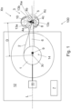
- Figure 1 is a schematic view of an embodiment of an arrangement, a vehicle and method for cable unwinding and winding in an electrically driven vehicle in partial cross-section
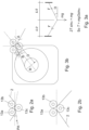
- Figures 2a and 2b are schematic views of a detail of the arrangement shown in Figure 1
- Figures 3a and 3b are schematic views of a geometrical principle.
- the electrically driven vehicle 12 is a mine machine or a construction machine.
- mines - such as underground mines and surface mines - and at other work sites different type of work machines are used.
- the work machine is provided with one or more working device(s).
- the mine machine may be provided with working device(s) for executing mine work task at a work site.
- the mine machine or a construction machine may be e.g.
- rock drilling rig a development drill, a tunneling drilling machine, a surface drilling machine, a bolting or reinforcing vehicle, a rock removal machine, a longhole drill rig, an explosive charging machine, a loader, a transport vehicle, a loading or hauling machine, setting vehicles of gallery arcs or nets, a concrete spraying machine, a crusher or a measuring vehicle.
- the arrangement 100 comprises a cable reel 1 for a cable 2 and arranged in the vehicle 12.
- a centre axis Xr of the cable reel 1 is arranged in vertical position.
- the cable reel 1 may also be arranged other ways: the centre axis Xr may be horizontally arranged, for instance.
- the cable 2 is arranged for supplying electric energy from an electrical network to the vehicle 12.
- the arrangement 100 further comprises a cable guiding arrangement 3 that receives and guides the cable 2.
- the cable guiding arrangement 3 comprises three wheels 13a - 13c that may rotate around their centre axis, respectively.
- the cable guiding arrangement 3 comprises three contacting surfaces 4a, 4b, 4c that are arranged parallel and in a triangle arrangement 5.
- the contacting surfaces 4a, 4b, 4c are on wheels rims.
- the wheels 13a - 13c, or at least one of them is/are rotatable, thus having ability to rotate with movements of the cable 2.
- the centre axis Xw of said wheels are arranged parallel with the normal axis Xn of the triangle arrangement 5. It is to be noted that said normal axis Xn is also normal of the plane of Figure 1 .
- At least one of the wheels 13a - 13c is not rotating, but the cable 2 is arranged to slide over said wheel(s).
- all the wheels 13a - 13c have a same diameter. However, this is not necessary, i.e. there may be wheels of different size.
- At least one of the contacting surfaces 4a, 4b, 4c, or eve all of them, is realized without a wheel.
- a sliding surface as the contacting surface.
- the sliding surface comprises arc-like or semicircle contacting surface made of PTFE.
- the sliding surface(s) may affect to the rotation angle A of the triangle arrangement 5.
- the contacting surfaces 4a, 4b, 4c are arranged and dimensioned such that the cable 2 being arranged between one of said contacting surfaces on its first side and two of said contacting surfaces on its second side bends on a surface of at least one of the contacting surfaces 4a, 4b, 4c.
- the cable guide arrangement 3 comprises a rotational axis Xc that is parallel with the normal axis Xn of the triangle arrangement 5.
- the rotational axis Xc of the cable guide arrangement 3 and the reel axis Xr are arranged in a same direction. In another embodiment, the axes Xc and Xr are oriented in different directions.
- the wheels 13a - 13c and thus the contacting surfaces 4a, 4b, 4c may rotate around said rotational axis Xc.
- said rotational axis Xc is arranged in the middle point of the triangle arrangement 5.
- the rotational axis Xc is arranged somewhat aside of said middle point, but anyway inside the triangle arrangement 5.
- the arrangement further comprises a control arm 6 in which the cable guide arrangement 3 is attached pivotally by the rotational axis Xc.
- the cable guide arrangement 3 may rotate freely in relation to the control arm 6.
- there is a damping means (not shown) that resists the rotational movement of the cable guide arrangement 3.
- the length of the control arm 6 is preferably selected so that the cable guiding arrangement 3 is able to move past the sides of the vehicle 12, as shown in Figure 4b .
- control arm 6 is arranged pivotally to a centre axis Xr of the cable reel so that the rotational axis Xc of the cable wheel arrangement lies at a first distance D from a centre axis Xr of the cable reel.
- the cable guide arrangement 3 may rotate in relation to the cable reel 1 together with the control arm 6.
- control arm 6 may rotate freely in relation to the cable reel 1.
- damping means (not shown) that resists the rotational movement of the control arm 6 in relation to the cable reel 1.
- actuator 14 there is an actuator 14 that is arranged to actively rotate the control arm 6 in relation to the cable reel 1.
- the actuator 14 may be controlled such that the control arm 6 is forced by a predetermined force to be parallel with the longitudinal axis L of the vehicle.
- the actuator 14 is arranged to turn the control arm 6 towards that side.
- the cable may be arranged so that vehicles moving on the same route do not run over the cable.
- the arrangement further comprises a controlling arrangement 7 that is connected to a force measuring system 8, a control arm sensor arrangement 9 and a triangle sensor arrangement 10.
- the force measuring system 8 is provided in at least one - even to all - of the guide surfaces 4a, 4b, 4c and arranged to measure force caused by the cable 2 against said guide surface(s).
- the force measuring system 8 is arranged for measuring force caused to the wheel 13c that is alone on the first side of the cable 2. Based on the measurement, the force measuring system 8 provides an information of force F for the controlling arrangement 7.
- the force measuring system 8 may comprise e.g. a strain gauge, a force transducer, a position transducer, a pressure cell, an eddy-current transducer, etc.
- the control arm sensor arrangement 9 is arranged to detect the direction in which the control arm 6 is pointing in relation to the longitudinal axis L of the electrically driven vehicle 12. Based on the detection, a control arm angle information CA is provided to the controlling arrangement 7.
- the control arm sensor arrangement 9 may comprise e.g. an optical encoder, a resistor potentiometer arrangement, a pulse transducer arrangement etc.
- the triangle sensor arrangement 10 is arranged to evaluate a rotation angle C (shown in Figure 3b ) of the triangle arrangement 5 in respect to the control arm 6. Based on the evaluation, a triangle angle information TA is provided to the controlling arrangement 7.
- the information may have just two values indicating if the cable 2 is contacting just one contacting surface 4a - 4c or all of the contacting surfaces 4a - 4c.
- the triangle sensor arrangement 10 may comprise e.g. an inductive limit switch or a microswitch. If a more accurate information on the rotation angle C is needed, the triangle sensor arrangement 10 may comprise e.g. an optical encoder, a resistor potentiometer arrangement, a pulse transducer arrangement etc.
- the controlling arrangement 7 is arranged to calculate an estimate of forces focusing on the cable 2 based on the force F, the control arm angle information CA and the triangle angle information TA. Referring to Figures 2a and 2b , the controlling arrangement 7 may be arranged to choose between two computation model in the calculation of the forces focused on the cable 2, based on the control arm angle information CA.
- the calculation of the forces focusing in the cable 2 is arranged to be based on a predetermined angle PA that is defined by dimensions of the cable wheel arrangement 3.
- the angle PA is in range of 2° - 5°, for instance 3°.
- Figure 3a is showing a geometrical principle that may be used for the calculation of the force focusing to the cable 2.
- angle " ⁇ " corresponds to the predetermined angle PA
- “mg” corresponds to the force affecting to the measured by the force measuring system 8
- the force focusing to the cable 2 corresponds to "T”.
- the calculation of the forces focusing in the cable 2 is arranged to be based on the rotation angle C and a current cable reel radius R.
- the radius R is measured by a sensor (not shown).
- the radius R is estimated indirectly on basis of turns of the cable on the reel.
- Figure 3b is showing a principle to define an angle A of force in this case.
- the angle A corresponds to angle ⁇ shown in Figure 3a .
- angle A angle C ⁇ angle B , wherein
- Figures 4a - 4c are schematic views of an arrangement and method for cable unwinding and winding in some directions of the cable 2.
- the cable 2 is contacting all the wheels, whereas in Figure 4c the cable 2 is contacting only one of the wheels.
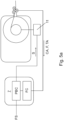
- Figure 5a is a schematic view of a method for cable unwinding and winding in an electrically driven vehicle in partial cross-section
- Figure 5b is showing a detail of Figure 5a .
- the variables for calculating the forces focused on the cable 2 are estimated on basis of force F, control arm angle information CA and triangle angle information TA that are measured and defined as described in this description.
- the method it is measured force caused by the cable against one of the contacting surfaces and created a value for the force F. Also, it is detected the direction in which the control arm 6 is pointing in relation to the longitudinal axis L of the electrically driven vehicle, and provided the control arm angle information CA. Furthermore, it is evaluated a rotation angle C of the triangle arrangement in respect to the control arm 6, and provided the triangle angle information TA. Then, the estimate of forces focused on the cable 2 is provided based on the force F, the control arm angle information CA and the triangle angle information TA. Force setpoint FS is given to the controlling arrangement 7, and a control signal S for controlling a reel motor 11 that is arranged to rotate the cable reel 1 is calculated (force calculation FC).
- a PID controller PBC may be used for providing the control signal S.
- Figure 5b is showing the PID calculation step and controller PBC shown in Figure 5a .
- Value of the force setpoint FS is continuously compared with value of the force calculation FC, and an error value or feedback difference is calculated as the difference of FS and FC.
- the controller PCB attempts to minimize the feedback difference, i.e. difference between FS and FC, by adjusting the control signal S.
- the calculation of the estimation and providing the control signal S may be realized by a controlling arrangement 7 that comprises a processor (CPU) with a memory configured to store program code and dynamic data.
- a processor CPU
- a memory configured to store program code and dynamic data.
- the control signal S is utilized in controlling the reel motor 11.
- the reel motor 11 is controlled such that the cable 2 is under a constant stress, or a certain range of stress, during use of the vehicle 12. In an embodiment, it is controlled torque of the reel motor 11.
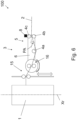
- Figure 6 is a schematic view of an example, useful for understanding the invention, J of the arrangement and method for cable unwinding and winding in an electrically driven vehicle.
- the contacting surfaces 4a, 4b, 4c of the cable guide arrangement 3 are arranged in another direction as the reel axis Xr.
- the reel axis Xr is perpendicular to centre axis of wheels making the contacting surfaces 4a, 4b, 4c.
- the centre axes of wheels are vertically aligned.
- the cable guiding arrangement 3 comprises control surfaces 16 that controls entry of the cable 2 to the triangle arrangement 5.
- the control surfaces 16 are wheels.
- the control arm 6 is arranged to rotate around a rotational axis arranged in close proximity of the control surfaces 16.
- the cable 2 is all the time contacting all the contacting surfaces 4a, 4b, 4c, and the calculation of the forces focusing in the cable 2 is based on a predetermined angle PA that is defined by dimensions of the cable wheel arrangement 3.
- the angle PA is in range of 2° - 5°, for instance 3° .
- the arrangement 100 further comprises a winding device 15 that makes it possible of winding and unwinding the cable 2 without problems even with very wide cable reels 1.
Landscapes
- Engineering & Computer Science (AREA)
- Mechanical Engineering (AREA)
- Power Engineering (AREA)
- Transportation (AREA)
- Life Sciences & Earth Sciences (AREA)
- Sustainable Development (AREA)
- Sustainable Energy (AREA)
- Storing, Repeated Paying-Out, And Re-Storing Of Elongated Articles (AREA)
- Electric Propulsion And Braking For Vehicles (AREA)
- Electric Cable Arrangement Between Relatively Moving Parts (AREA)
Claims (12)
- Anordnung (100) zum Abwickeln und Aufwickeln von Kabeln in einem elektrisch angetriebenen Fahrzeug, wobei die Anordnung umfasst:- eine Kabelhaspel (1) für ein Kabel (2),- eine Kabelführungsanordnung (3) zum Aufnehmen und Führen des Kabels (2),- wobei die Kabelführungsanordnung (3) drei Kontaktflächen (4a, 4b, 4c) umfasst,
die parallel und in einer Dreiecksanordnung (5) angeordnet sind,- wobei die Kontaktflächen (4a, 4b, 4c) in der Kabelführungsanordnung (3) so angeordnet und dimensioniert sind, dass sich das zwischen einer der Kontaktflächen auf seiner ersten Seite und zwei der Kontaktflächen auf seiner zweiten Seite angeordnete Kabel (2) an einer Oberfläche von mindestens einer der Kontaktflächen (4a, 4b, 4c) biegt,- wobei die Anordnung weiter einen Lenker (6) und eine Steueranordnung (7) umfasst, wobei die Steueranordnung (7) Folgendes umfasst- ein Kraftmesssystem (8), das in mindestens einer der Kontaktflächen (4a, 4b, 4c) bereitgestellt und so angeordnet ist, dass es die durch das Kabel gegen die Kontaktfläche(n) verursachte Kraft misst, wobei das Kraftmesssystem (8) eine Kraft (F) bereitstellt,- eine Lenkersensoranordnung (9), die dazu angeordnet ist, dass sie die Richtung erkennt, in die der Lenker (6) in Bezug auf die Längsachse (L) des elektrisch angetriebenen Fahrzeugs zeigt, und um Lenkerwinkelinformationen (CA) bereitzustellen, wobei- die Kabelführungsanordnung (3) eine zur Normalachse (Xn) der Dreiecksanordnung (5) parallele Drehachse (Xc) umfasst,- die Drehachse (Xc) der Kabelführungsanordnung und die Mittelachse (Xr) der Kabelhaspel in einer gleichen Richtung angeordnet sind,- die Kabelführungsanordnung (3) schwenkbar im Lenker (6) befestigt ist, und- der Lenker (6) schwenkbar um eine Mittelachse (Xr) der Kabelhaspel angeordnet ist, so dass- die Drehachse (Xc) der Kabelführungsanordnung bei einem ersten Abstand (D) von der Mittelachse (Xr) der Kabelhaspel liegt und relativ zur Kabelhaspel drehbar ist, und- eine Dreieckssensoranordnung (10) so angeordnet ist, dass sie einen Drehwinkel (A) der Dreiecksanordnung (5) in Bezug auf den Lenker (6) auswertet, um Dreieckswinkelinformationen (TA) bereitzustellen, und wobeidie Steueranordnung (7) angeordnet ist, um basierend auf der Kraft (F), den Lenkerwinkelinformationen (CA) und den Dreieckswinkelinformationen (TA) eine Schätzung der auf das Kabel (2) konzentrierten Kräfte zu berechnen. - Anordnung nach Anspruch 1, wobei die Kabelführungsanordnung (3) drei Räder (13a - 13c) umfasst, sich die Kontaktflächen (4a, 4b, 4c) auf der Radfelge befinden,die Mittelachse (Xw) der Räder parallel zur Normalachse (Xn) der Dreiecksanordnung (5) angeordnet ist, und wobeidie Drehachse (Xc) der Kabelführungsanordnung innerhalb der Dreiecksanordnung (5) angeordnet ist.
- Anordnung nach Anspruch 1 oder 2, wobei die Steueranordnung (7) angeordnet ist, bei der Berechnung der auf das Kabel (2) konzentrierten Kräfte basierend auf den Lenkerwinkelinformationen (CA) zwischen zwei Berechnungsmodellen zu wählen.
- Anordnung nach Anspruch 3, wobei in dem Fall, dass die Lenkersensoranordnung (9) erkennt, dass der Lenker (6) in eine Richtung zeigt, in der das Kabel (2) nur eine der Kontaktflächen (4a, 4b, 4c) berührt, die Berechnung der Kräfte, die sich in dem Kabel (2) konzentrieren, so angeordnet ist, dass sie auf dem Drehwinkel (A) und einem aktuellen Kabelhaspelradius (R) basiert, und wobei
für den Fall, dass die Lenkersensoranordnung (9) erkennt, dass der Lenker (6) in eine Richtung zeigt, in der das Kabel (2) alle Kontaktflächen (4a, 4b, 4c) berührt, die Berechnung der Kräfte, die sich in dem Kabel (2) konzentrieren, so angeordnet ist, dass sie auf einem vorbestimmten Winkel (PA) basiert, wobei der vorbestimmte Winkel (PA) von den Abmessungen der Leitrollenanordnung (3) definiert wird. - Anordnung nach Anspruch 1 oder 2, wobei die Kontaktflächen (4a, 4b, 4c) der Kabelführungsanordnung (3) in einer anderen Richtung als die Haspelachse (Xr) angeordnet sind.
- Elektrisch angetriebenes Fahrzeug (12), umfassend die Anordnung nach einem der vorstehenden Ansprüche.
- Fahrzeug nach Anspruch 6, wobei es eine Bergwerksmaschine ist.
- Fahrzeug nach Anspruch 6, wobei es eine Baumaschine ist.
- Verfahren zum Steuern vom Aufwickeln und Abwickeln von Kabeln (2) in einem elektrisch angetriebenen Fahrzeug, wobei bei dem Verfahren eine Anordnung verwendet wird, die Folgendes umfasst- eine Kabelhaspel (1) für ein Kabel (2),- eine Kabelführungsanordnung (3) zum Aufnehmen und Führen des Kabels (2),- wobei die Kabelführungsanordnung (3) drei parallel und in einer Dreiecksanordnung (5) angeordnete Kontaktflächen (4a, 4b, 4c) umfasst,- wobei die Kontaktflächen (4a, 4b, 4c) in der Kabelführungsanordnung (3) so angeordnet und dimensioniert sind, dass sich das zwischen einer der Kontaktflächen auf seiner ersten Seite und zwei der Kontaktflächen auf seiner zweiten Seite angeordnete Kabel an einer Oberfläche von mindestens einer der Kontaktflächen (4a, 4b, 4c) biegt,- wobei die Anordnung weiter einen Lenker (6) und eine Steueranordnung (7) umfasst, wobei- die Kabelführungsanordnung (3) eine zur Normalachse (Xn) der Dreiecksanordnung (5) parallele Drehachse (Xc) umfasst, und- die Seilführungsanordnung (3) um die Drehachse (Xc) schwenkbar im Lenker (6) befestigt ist, und- der Lenker (6) schwenkbar um eine Mittelachse (Xr) der Kabelhaspel angeordnet ist, so dass- die Drehachse (Xc) der Kabelführungsanordnung bei einem ersten Abstand (D) von einer Mittelachse (Xr) der Kabelhaspel liegt und eine Rotationsfähigkeit in Bezug auf die Kabelhaspel aufweist, wobei das Verfahren Folgendes umfasst:- Messen der vom Kabel gegen eine der Kontaktflächen ausgeübten Kraft und Erzeugen eines Werts für eine Kraft (F),- Erkennen der Richtung, in die der Lenker (6) in Bezug auf die Längsachse (L) des elektrisch angetriebenen Fahrzeugs zeigt, wodurch Lenkerwinkelinformationen (CA) bereitgestellt werden,- Bewerten eines Drehwinkels (C) der Dreiecksanordnung in Bezug auf den Lenker (6), wodurch Dreieckswinkelinformationen (TA) bereitgestellt werden, und- Berechnen einer Schätzung der Kräfte, die auf das Kabel (2) konzentriert sind, basierend auf der Kraft (F), den Lenkerwinkelinformationen (CA) und den Dreieckswinkelinformationen (TA).
- Verfahren nach Anspruch 9, das Wählen zwischen zwei Berechnungsmodellen bei der Berechnung der auf das Kabel (2) konzentrierten Kräfte basierend auf den Lenkerwinkelinformationen (CA) umfasst.
- Verfahren nach Anspruch 10, wobei im Fall, dass der Lenker (6) in eine Richtung zeigt, in der das Kabel (2) nur eine der Kontaktflächen (4a, 4b, 4c) berührt:Berechnen der Kräfte, die sich in dem Kabel (2) konzentrieren, basierend auf dem Drehwinkel (C) und einem aktuellen Kabelhaspelradius (R), und wobeiim Fall, dass der Lenker (6) in eine Richtung zeigt, in der das Kabel (2) alle Kontaktflächen (4a, 4b, 4c) berührt:
Berechnen der in dem Kabel (2) konzentrierten Kräfte basierend auf einem vorbestimmten Winkel (PA), wobei der vorbestimmte Winkel (PA) durch Abmessungen der Leitrollenanordnung (3) definiert wird. - Verfahren nach einem der Ansprüche 9 - 11, umfassend Steuern des Drehmoments eines Aufwickelmotors (11) und Verwenden berechneter Kräfte, die sich in dem Kabel (2) konzentrieren, beim Steuern des Drehmoments.
Priority Applications (7)
| Application Number | Priority Date | Filing Date | Title |
|---|---|---|---|
| PL20154047.3T PL3859925T3 (pl) | 2020-01-28 | 2020-01-28 | Układ, pojazd oraz sposób |
| EP20154047.3A EP3859925B1 (de) | 2020-01-28 | 2020-01-28 | Anordnung, fahrzeug und verfahren |
| FIEP20154047.3T FI3859925T3 (fi) | 2020-01-28 | 2020-01-28 | Järjestely, ajoneuvo ja menetelmä |
| AU2021215007A AU2021215007B2 (en) | 2020-01-28 | 2021-01-28 | Arrangement, vehicle and method for cable winding and unwinding |
| CA3163991A CA3163991A1 (en) | 2020-01-28 | 2021-01-28 | Arrangement, vehicle and method for cable winding and unwinding |
| CN202180009936.9A CN115004495A (zh) | 2020-01-28 | 2021-01-28 | 用于电缆卷绕和解绕的装置、车辆和方法 |
| PCT/EP2021/052031 WO2021152042A1 (en) | 2020-01-28 | 2021-01-28 | Arrangement, vehicle and method for cable winding and unwinding |
Applications Claiming Priority (1)
| Application Number | Priority Date | Filing Date | Title |
|---|---|---|---|
| EP20154047.3A EP3859925B1 (de) | 2020-01-28 | 2020-01-28 | Anordnung, fahrzeug und verfahren |
Publications (2)
| Publication Number | Publication Date |
|---|---|
| EP3859925A1 EP3859925A1 (de) | 2021-08-04 |
| EP3859925B1 true EP3859925B1 (de) | 2023-09-06 |
Family
ID=69571759
Family Applications (1)
| Application Number | Title | Priority Date | Filing Date |
|---|---|---|---|
| EP20154047.3A Active EP3859925B1 (de) | 2020-01-28 | 2020-01-28 | Anordnung, fahrzeug und verfahren |
Country Status (7)
| Country | Link |
|---|---|
| EP (1) | EP3859925B1 (de) |
| CN (1) | CN115004495A (de) |
| AU (1) | AU2021215007B2 (de) |
| CA (1) | CA3163991A1 (de) |
| FI (1) | FI3859925T3 (de) |
| PL (1) | PL3859925T3 (de) |
| WO (1) | WO2021152042A1 (de) |
Families Citing this family (4)
| Publication number | Priority date | Publication date | Assignee | Title |
|---|---|---|---|---|
| US20230063279A1 (en) * | 2021-09-02 | 2023-03-02 | Reel Power Licensing Corp. | Oscillating traverse coiler |
| EP4180378A1 (de) * | 2021-11-16 | 2023-05-17 | Kingfisher International Products Limited | Führungs- und zuführungssystem für aufwickelbares material |
| CN116853907A (zh) * | 2023-06-28 | 2023-10-10 | 中联重科土方机械有限公司 | 用于控制电缆收放的方法、电缆收放装置及控制器 |
| CN120697596B (zh) * | 2025-07-10 | 2026-01-23 | 利嘉新能源有限公司 | 一种智能充电桩 |
Family Cites Families (7)
| Publication number | Priority date | Publication date | Assignee | Title |
|---|---|---|---|---|
| JP3050349B2 (ja) * | 1993-02-26 | 2000-06-12 | スズキ株式会社 | ケーブル巻取装置 |
| JP3022076B2 (ja) * | 1993-07-21 | 2000-03-15 | スズキ株式会社 | 遠隔操縦車両用ケーブル状態制御装置 |
| FI100039B (fi) * | 1996-02-02 | 1997-08-29 | Tamrock Loaders Oy | Menetelmä ja sovitelma sähkökäyttöisen ajoneuvon kaapelin kelaamisen j a purkamisen ohjaamiseksi |
| RU2543175C2 (ru) * | 2010-02-18 | 2015-02-27 | Симпелькамп Машинен-Унд Анлагенбау Гмбх | Устройство и способ изготовления ленточных конвейеров со стальным тросом, имеющим сердечник |
| DE102011080082A1 (de) * | 2011-07-29 | 2013-01-31 | Kiekert Ag | Lagereinrichtung mit Kabelführung für ein Elektrofahrzeug |
| GB2497666A (en) * | 2011-12-13 | 2013-06-19 | Joy Mm Delaware Inc | Swinging sheave bracket with force control |
| DE202013104456U1 (de) * | 2013-10-01 | 2013-10-14 | Bernhard Kummert | Kabelspeichervorrichtung |
-
2020
- 2020-01-28 EP EP20154047.3A patent/EP3859925B1/de active Active
- 2020-01-28 FI FIEP20154047.3T patent/FI3859925T3/fi active
- 2020-01-28 PL PL20154047.3T patent/PL3859925T3/pl unknown
-
2021
- 2021-01-28 CN CN202180009936.9A patent/CN115004495A/zh active Pending
- 2021-01-28 CA CA3163991A patent/CA3163991A1/en active Pending
- 2021-01-28 AU AU2021215007A patent/AU2021215007B2/en active Active
- 2021-01-28 WO PCT/EP2021/052031 patent/WO2021152042A1/en not_active Ceased
Also Published As
| Publication number | Publication date |
|---|---|
| CN115004495A (zh) | 2022-09-02 |
| FI3859925T3 (fi) | 2023-10-02 |
| CA3163991A1 (en) | 2021-08-05 |
| EP3859925A1 (de) | 2021-08-04 |
| WO2021152042A1 (en) | 2021-08-05 |
| PL3859925T3 (pl) | 2023-12-27 |
| AU2021215007B2 (en) | 2026-02-12 |
| AU2021215007A1 (en) | 2022-08-04 |
Similar Documents
| Publication | Publication Date | Title |
|---|---|---|
| EP3859925B1 (de) | Anordnung, fahrzeug und verfahren | |
| US9389130B2 (en) | Assembly, system and method for cable tension measurement | |
| US8612175B2 (en) | Measurement device and a system and method for using the same | |
| KR20130093545A (ko) | 토크를 검출하기 위한 방법 및 산업용 로봇 | |
| CN102020199A (zh) | 用于确定由起重机的起重索承载的负载的负载质量的系统 | |
| EP2821188A1 (de) | Positionssteuerungsvorrichtung mit joystick | |
| MX2011010596A (es) | Sistema y ensamble de medicion de cable de alta tension. | |
| EP3417144B1 (de) | Systeme und verfahren zum messen der krümmung, des gewichts auf dem bohreinsatz und des drehmoments auf dem bohreinsatz beim bohren | |
| CN105452148A (zh) | 用于起重机的长度角度传感器的智能的电机制动器 | |
| AU2019205026B2 (en) | Cable handling system for longwall mining machines | |
| CN101774509B (zh) | 自动控制物体与地面距离的系统及其控制方法 | |
| CN110244705A (zh) | 一种自动导引小车的行走校准装置及校准方法 | |
| Bi et al. | Study on theory and methods of payload online estimation for cable shovels | |
| KR101058198B1 (ko) | 휠 로더의 로딩 자동화 실험장치 | |
| JP7056801B2 (ja) | 回転杭の施工方法、杭群の製造方法、杭群、回転杭の施工管理装置、及び回転杭の施工管理システム | |
| JP2004157088A (ja) | ねじ特性の測定方法および測定装置 | |
| EP2815993B1 (de) | Spleißüberwachungssystem für Förderbänder in der Bergbauindustrie | |
| EA043361B1 (ru) | Устройство, транспортное средство и способ наматывания и разматывания кабеля | |
| KR102868515B1 (ko) | 크레인의 수명 예측 시스템 | |
| CN121048026B (zh) | 三圆顶管机纠扭方法及装置 | |
| CN115605423B (zh) | 用于运行起重设备的方法和用于实施该方法的起重设备 | |
| JPH0474651B2 (de) | ||
| KR101804770B1 (ko) | 네비가이더, 네비가이더를 이용한 이동 로봇 및 이동 로봇의 가이드 방법 | |
| US20200370420A1 (en) | Drill head position determination system | |
| CN121781903A (zh) | 钻孔深度控制系统、钻机及钻孔深度控制方法 |
Legal Events
| Date | Code | Title | Description |
|---|---|---|---|
| PUAI | Public reference made under article 153(3) epc to a published international application that has entered the european phase |
Free format text: ORIGINAL CODE: 0009012 |
|
| STAA | Information on the status of an ep patent application or granted ep patent |
Free format text: STATUS: THE APPLICATION HAS BEEN PUBLISHED |
|
| AK | Designated contracting states |
Kind code of ref document: A1 Designated state(s): AL AT BE BG CH CY CZ DE DK EE ES FI FR GB GR HR HU IE IS IT LI LT LU LV MC MK MT NL NO PL PT RO RS SE SI SK SM TR |
|
| STAA | Information on the status of an ep patent application or granted ep patent |
Free format text: STATUS: REQUEST FOR EXAMINATION WAS MADE |
|
| 17P | Request for examination filed |
Effective date: 20220204 |
|
| RBV | Designated contracting states (corrected) |
Designated state(s): AL AT BE BG CH CY CZ DE DK EE ES FI FR GB GR HR HU IE IS IT LI LT LU LV MC MK MT NL NO PL PT RO RS SE SI SK SM TR |
|
| REG | Reference to a national code |
Ref country code: DE Ref legal event code: R079 Free format text: PREVIOUS MAIN CLASS: H02G0011000000 Ipc: B65H0059380000 Ref document number: 602020016985 Country of ref document: DE |
|
| GRAP | Despatch of communication of intention to grant a patent |
Free format text: ORIGINAL CODE: EPIDOSNIGR1 |
|
| STAA | Information on the status of an ep patent application or granted ep patent |
Free format text: STATUS: GRANT OF PATENT IS INTENDED |
|
| RIC1 | Information provided on ipc code assigned before grant |
Ipc: B60L 9/00 20060101ALI20230222BHEP Ipc: B65H 75/42 20060101ALI20230222BHEP Ipc: H02G 11/02 20060101ALI20230222BHEP Ipc: B60L 5/00 20060101ALI20230222BHEP Ipc: B66D 1/48 20060101ALI20230222BHEP Ipc: B66D 1/38 20060101ALI20230222BHEP Ipc: B65H 75/44 20060101ALI20230222BHEP Ipc: B65H 59/38 20060101AFI20230222BHEP |
|
| INTG | Intention to grant announced |
Effective date: 20230329 |
|
| P01 | Opt-out of the competence of the unified patent court (upc) registered |
Effective date: 20230603 |
|
| GRAS | Grant fee paid |
Free format text: ORIGINAL CODE: EPIDOSNIGR3 |
|
| GRAA | (expected) grant |
Free format text: ORIGINAL CODE: 0009210 |
|
| STAA | Information on the status of an ep patent application or granted ep patent |
Free format text: STATUS: THE PATENT HAS BEEN GRANTED |
|
| AK | Designated contracting states |
Kind code of ref document: B1 Designated state(s): AL AT BE BG CH CY CZ DE DK EE ES FI FR GB GR HR HU IE IS IT LI LT LU LV MC MK MT NL NO PL PT RO RS SE SI SK SM TR |
|
| REG | Reference to a national code |
Ref country code: GB Ref legal event code: FG4D |
|
| REG | Reference to a national code |
Ref country code: CH Ref legal event code: EP |
|
| REG | Reference to a national code |
Ref country code: IE Ref legal event code: FG4D |
|
| REG | Reference to a national code |
Ref country code: DE Ref legal event code: R096 Ref document number: 602020016985 Country of ref document: DE |
|
| REG | Reference to a national code |
Ref country code: FI Ref legal event code: FGE |
|
| REG | Reference to a national code |
Ref country code: SE Ref legal event code: TRGR |
|
| REG | Reference to a national code |
Ref country code: LT Ref legal event code: MG9D |
|
| REG | Reference to a national code |
Ref country code: NL Ref legal event code: MP Effective date: 20230906 |
|
| PG25 | Lapsed in a contracting state [announced via postgrant information from national office to epo] |
Ref country code: GR Free format text: LAPSE BECAUSE OF FAILURE TO SUBMIT A TRANSLATION OF THE DESCRIPTION OR TO PAY THE FEE WITHIN THE PRESCRIBED TIME-LIMIT Effective date: 20231207 |
|
| PG25 | Lapsed in a contracting state [announced via postgrant information from national office to epo] |
Ref country code: RS Free format text: LAPSE BECAUSE OF FAILURE TO SUBMIT A TRANSLATION OF THE DESCRIPTION OR TO PAY THE FEE WITHIN THE PRESCRIBED TIME-LIMIT Effective date: 20230906 Ref country code: NO Free format text: LAPSE BECAUSE OF FAILURE TO SUBMIT A TRANSLATION OF THE DESCRIPTION OR TO PAY THE FEE WITHIN THE PRESCRIBED TIME-LIMIT Effective date: 20231206 Ref country code: LV Free format text: LAPSE BECAUSE OF FAILURE TO SUBMIT A TRANSLATION OF THE DESCRIPTION OR TO PAY THE FEE WITHIN THE PRESCRIBED TIME-LIMIT Effective date: 20230906 Ref country code: LT Free format text: LAPSE BECAUSE OF FAILURE TO SUBMIT A TRANSLATION OF THE DESCRIPTION OR TO PAY THE FEE WITHIN THE PRESCRIBED TIME-LIMIT Effective date: 20230906 Ref country code: HR Free format text: LAPSE BECAUSE OF FAILURE TO SUBMIT A TRANSLATION OF THE DESCRIPTION OR TO PAY THE FEE WITHIN THE PRESCRIBED TIME-LIMIT Effective date: 20230906 Ref country code: GR Free format text: LAPSE BECAUSE OF FAILURE TO SUBMIT A TRANSLATION OF THE DESCRIPTION OR TO PAY THE FEE WITHIN THE PRESCRIBED TIME-LIMIT Effective date: 20231207 |
|
| REG | Reference to a national code |
Ref country code: AT Ref legal event code: MK05 Ref document number: 1608323 Country of ref document: AT Kind code of ref document: T Effective date: 20230906 |
|
| PG25 | Lapsed in a contracting state [announced via postgrant information from national office to epo] |
Ref country code: NL Free format text: LAPSE BECAUSE OF FAILURE TO SUBMIT A TRANSLATION OF THE DESCRIPTION OR TO PAY THE FEE WITHIN THE PRESCRIBED TIME-LIMIT Effective date: 20230906 |
|
| PG25 | Lapsed in a contracting state [announced via postgrant information from national office to epo] |
Ref country code: IS Free format text: LAPSE BECAUSE OF FAILURE TO SUBMIT A TRANSLATION OF THE DESCRIPTION OR TO PAY THE FEE WITHIN THE PRESCRIBED TIME-LIMIT Effective date: 20240106 |
|
| PG25 | Lapsed in a contracting state [announced via postgrant information from national office to epo] |
Ref country code: AT Free format text: LAPSE BECAUSE OF FAILURE TO SUBMIT A TRANSLATION OF THE DESCRIPTION OR TO PAY THE FEE WITHIN THE PRESCRIBED TIME-LIMIT Effective date: 20230906 |
|
| PG25 | Lapsed in a contracting state [announced via postgrant information from national office to epo] |
Ref country code: ES Free format text: LAPSE BECAUSE OF FAILURE TO SUBMIT A TRANSLATION OF THE DESCRIPTION OR TO PAY THE FEE WITHIN THE PRESCRIBED TIME-LIMIT Effective date: 20230906 |
|
| PG25 | Lapsed in a contracting state [announced via postgrant information from national office to epo] |
Ref country code: SM Free format text: LAPSE BECAUSE OF FAILURE TO SUBMIT A TRANSLATION OF THE DESCRIPTION OR TO PAY THE FEE WITHIN THE PRESCRIBED TIME-LIMIT Effective date: 20230906 Ref country code: RO Free format text: LAPSE BECAUSE OF FAILURE TO SUBMIT A TRANSLATION OF THE DESCRIPTION OR TO PAY THE FEE WITHIN THE PRESCRIBED TIME-LIMIT Effective date: 20230906 Ref country code: IS Free format text: LAPSE BECAUSE OF FAILURE TO SUBMIT A TRANSLATION OF THE DESCRIPTION OR TO PAY THE FEE WITHIN THE PRESCRIBED TIME-LIMIT Effective date: 20240106 Ref country code: ES Free format text: LAPSE BECAUSE OF FAILURE TO SUBMIT A TRANSLATION OF THE DESCRIPTION OR TO PAY THE FEE WITHIN THE PRESCRIBED TIME-LIMIT Effective date: 20230906 Ref country code: EE Free format text: LAPSE BECAUSE OF FAILURE TO SUBMIT A TRANSLATION OF THE DESCRIPTION OR TO PAY THE FEE WITHIN THE PRESCRIBED TIME-LIMIT Effective date: 20230906 Ref country code: AT Free format text: LAPSE BECAUSE OF FAILURE TO SUBMIT A TRANSLATION OF THE DESCRIPTION OR TO PAY THE FEE WITHIN THE PRESCRIBED TIME-LIMIT Effective date: 20230906 Ref country code: PT Free format text: LAPSE BECAUSE OF FAILURE TO SUBMIT A TRANSLATION OF THE DESCRIPTION OR TO PAY THE FEE WITHIN THE PRESCRIBED TIME-LIMIT Effective date: 20240108 Ref country code: SK Free format text: LAPSE BECAUSE OF FAILURE TO SUBMIT A TRANSLATION OF THE DESCRIPTION OR TO PAY THE FEE WITHIN THE PRESCRIBED TIME-LIMIT Effective date: 20230906 |
|
| PG25 | Lapsed in a contracting state [announced via postgrant information from national office to epo] |
Ref country code: IT Free format text: LAPSE BECAUSE OF FAILURE TO SUBMIT A TRANSLATION OF THE DESCRIPTION OR TO PAY THE FEE WITHIN THE PRESCRIBED TIME-LIMIT Effective date: 20230906 |
|
| REG | Reference to a national code |
Ref country code: DE Ref legal event code: R097 Ref document number: 602020016985 Country of ref document: DE |
|
| PG25 | Lapsed in a contracting state [announced via postgrant information from national office to epo] |
Ref country code: DK Free format text: LAPSE BECAUSE OF FAILURE TO SUBMIT A TRANSLATION OF THE DESCRIPTION OR TO PAY THE FEE WITHIN THE PRESCRIBED TIME-LIMIT Effective date: 20230906 |
|
| PLBE | No opposition filed within time limit |
Free format text: ORIGINAL CODE: 0009261 |
|
| STAA | Information on the status of an ep patent application or granted ep patent |
Free format text: STATUS: NO OPPOSITION FILED WITHIN TIME LIMIT |
|
| PG25 | Lapsed in a contracting state [announced via postgrant information from national office to epo] |
Ref country code: DK Free format text: LAPSE BECAUSE OF FAILURE TO SUBMIT A TRANSLATION OF THE DESCRIPTION OR TO PAY THE FEE WITHIN THE PRESCRIBED TIME-LIMIT Effective date: 20230906 Ref country code: SI Free format text: LAPSE BECAUSE OF FAILURE TO SUBMIT A TRANSLATION OF THE DESCRIPTION OR TO PAY THE FEE WITHIN THE PRESCRIBED TIME-LIMIT Effective date: 20230906 |
|
| 26N | No opposition filed |
Effective date: 20240607 |
|
| PG25 | Lapsed in a contracting state [announced via postgrant information from national office to epo] |
Ref country code: MC Free format text: LAPSE BECAUSE OF FAILURE TO SUBMIT A TRANSLATION OF THE DESCRIPTION OR TO PAY THE FEE WITHIN THE PRESCRIBED TIME-LIMIT Effective date: 20230906 |
|
| PG25 | Lapsed in a contracting state [announced via postgrant information from national office to epo] |
Ref country code: MC Free format text: LAPSE BECAUSE OF FAILURE TO SUBMIT A TRANSLATION OF THE DESCRIPTION OR TO PAY THE FEE WITHIN THE PRESCRIBED TIME-LIMIT Effective date: 20230906 |
|
| REG | Reference to a national code |
Ref country code: CH Ref legal event code: PL |
|
| PG25 | Lapsed in a contracting state [announced via postgrant information from national office to epo] |
Ref country code: LU Free format text: LAPSE BECAUSE OF NON-PAYMENT OF DUE FEES Effective date: 20240128 |
|
| GBPC | Gb: european patent ceased through non-payment of renewal fee |
Effective date: 20240128 |
|
| PG25 | Lapsed in a contracting state [announced via postgrant information from national office to epo] |
Ref country code: LU Free format text: LAPSE BECAUSE OF NON-PAYMENT OF DUE FEES Effective date: 20240128 |
|
| PG25 | Lapsed in a contracting state [announced via postgrant information from national office to epo] |
Ref country code: GB Free format text: LAPSE BECAUSE OF NON-PAYMENT OF DUE FEES Effective date: 20240128 |
|
| PG25 | Lapsed in a contracting state [announced via postgrant information from national office to epo] |
Ref country code: BE Free format text: LAPSE BECAUSE OF NON-PAYMENT OF DUE FEES Effective date: 20240131 |
|
| PG25 | Lapsed in a contracting state [announced via postgrant information from national office to epo] |
Ref country code: CH Free format text: LAPSE BECAUSE OF NON-PAYMENT OF DUE FEES Effective date: 20240131 |
|
| PG25 | Lapsed in a contracting state [announced via postgrant information from national office to epo] |
Ref country code: GB Free format text: LAPSE BECAUSE OF NON-PAYMENT OF DUE FEES Effective date: 20240128 Ref country code: CH Free format text: LAPSE BECAUSE OF NON-PAYMENT OF DUE FEES Effective date: 20240131 Ref country code: BE Free format text: LAPSE BECAUSE OF NON-PAYMENT OF DUE FEES Effective date: 20240131 |
|
| REG | Reference to a national code |
Ref country code: BE Ref legal event code: MM Effective date: 20240131 |
|
| PG25 | Lapsed in a contracting state [announced via postgrant information from national office to epo] |
Ref country code: BG Free format text: LAPSE BECAUSE OF FAILURE TO SUBMIT A TRANSLATION OF THE DESCRIPTION OR TO PAY THE FEE WITHIN THE PRESCRIBED TIME-LIMIT Effective date: 20230906 |
|
| PG25 | Lapsed in a contracting state [announced via postgrant information from national office to epo] |
Ref country code: BG Free format text: LAPSE BECAUSE OF FAILURE TO SUBMIT A TRANSLATION OF THE DESCRIPTION OR TO PAY THE FEE WITHIN THE PRESCRIBED TIME-LIMIT Effective date: 20230906 |
|
| PG25 | Lapsed in a contracting state [announced via postgrant information from national office to epo] |
Ref country code: IE Free format text: LAPSE BECAUSE OF NON-PAYMENT OF DUE FEES Effective date: 20240128 |
|
| PG25 | Lapsed in a contracting state [announced via postgrant information from national office to epo] |
Ref country code: IE Free format text: LAPSE BECAUSE OF NON-PAYMENT OF DUE FEES Effective date: 20240128 |
|
| PG25 | Lapsed in a contracting state [announced via postgrant information from national office to epo] |
Ref country code: CY Free format text: LAPSE BECAUSE OF FAILURE TO SUBMIT A TRANSLATION OF THE DESCRIPTION OR TO PAY THE FEE WITHIN THE PRESCRIBED TIME-LIMIT; INVALID AB INITIO Effective date: 20200128 |
|
| PG25 | Lapsed in a contracting state [announced via postgrant information from national office to epo] |
Ref country code: HU Free format text: LAPSE BECAUSE OF FAILURE TO SUBMIT A TRANSLATION OF THE DESCRIPTION OR TO PAY THE FEE WITHIN THE PRESCRIBED TIME-LIMIT; INVALID AB INITIO Effective date: 20200128 |
|
| PG25 | Lapsed in a contracting state [announced via postgrant information from national office to epo] |
Ref country code: TR Free format text: LAPSE BECAUSE OF FAILURE TO SUBMIT A TRANSLATION OF THE DESCRIPTION OR TO PAY THE FEE WITHIN THE PRESCRIBED TIME-LIMIT Effective date: 20230906 |
|
| PGFP | Annual fee paid to national office [announced via postgrant information from national office to epo] |
Ref country code: FI Payment date: 20251230 Year of fee payment: 7 |
|
| PGFP | Annual fee paid to national office [announced via postgrant information from national office to epo] |
Ref country code: FR Payment date: 20251222 Year of fee payment: 7 |
|
| PGFP | Annual fee paid to national office [announced via postgrant information from national office to epo] |
Ref country code: SE Payment date: 20251210 Year of fee payment: 7 |
|
| PGFP | Annual fee paid to national office [announced via postgrant information from national office to epo] |
Ref country code: CZ Payment date: 20251229 Year of fee payment: 7 |
|
| PGFP | Annual fee paid to national office [announced via postgrant information from national office to epo] |
Ref country code: PL Payment date: 20251212 Year of fee payment: 7 |
|
| PGFP | Annual fee paid to national office [announced via postgrant information from national office to epo] |
Ref country code: DE Payment date: 20251203 Year of fee payment: 7 |