EP3859953A1 - Empilement de tôles pour une machine électrique rotative - Google Patents
Empilement de tôles pour une machine électrique rotative Download PDFInfo
- Publication number
- EP3859953A1 EP3859953A1 EP20154886.4A EP20154886A EP3859953A1 EP 3859953 A1 EP3859953 A1 EP 3859953A1 EP 20154886 A EP20154886 A EP 20154886A EP 3859953 A1 EP3859953 A1 EP 3859953A1
- Authority
- EP
- European Patent Office
- Prior art keywords
- laminated core
- laminated
- coating
- core
- stator
- Prior art date
- Legal status (The legal status is an assumption and is not a legal conclusion. Google has not performed a legal analysis and makes no representation as to the accuracy of the status listed.)
- Withdrawn
Links
- 238000000576 coating method Methods 0.000 claims abstract description 45
- 239000011248 coating agent Substances 0.000 claims abstract description 44
- 238000000034 method Methods 0.000 claims abstract description 31
- 229910052751 metal Inorganic materials 0.000 claims abstract description 17
- 239000002184 metal Substances 0.000 claims abstract description 17
- 239000000853 adhesive Substances 0.000 claims abstract description 14
- 230000001070 adhesive effect Effects 0.000 claims abstract description 14
- 239000007769 metal material Substances 0.000 claims abstract description 12
- 238000007751 thermal spraying Methods 0.000 claims abstract description 10
- 238000003475 lamination Methods 0.000 claims description 15
- XEEYBQQBJWHFJM-UHFFFAOYSA-N Iron Chemical compound [Fe] XEEYBQQBJWHFJM-UHFFFAOYSA-N 0.000 claims description 14
- 238000005507 spraying Methods 0.000 claims description 13
- 229910052782 aluminium Inorganic materials 0.000 claims description 11
- XAGFODPZIPBFFR-UHFFFAOYSA-N aluminium Chemical compound [Al] XAGFODPZIPBFFR-UHFFFAOYSA-N 0.000 claims description 11
- 238000004519 manufacturing process Methods 0.000 claims description 9
- 229910052742 iron Inorganic materials 0.000 claims description 7
- 238000005245 sintering Methods 0.000 claims description 7
- 238000001816 cooling Methods 0.000 claims description 6
- 239000007921 spray Substances 0.000 description 13
- 239000000463 material Substances 0.000 description 7
- 239000002245 particle Substances 0.000 description 6
- 238000009434 installation Methods 0.000 description 5
- 239000002966 varnish Substances 0.000 description 4
- 230000005291 magnetic effect Effects 0.000 description 3
- 229910001220 stainless steel Inorganic materials 0.000 description 3
- 239000010935 stainless steel Substances 0.000 description 3
- 239000000654 additive Substances 0.000 description 2
- 239000011230 binding agent Substances 0.000 description 2
- 238000003754 machining Methods 0.000 description 2
- 238000002844 melting Methods 0.000 description 2
- 230000008018 melting Effects 0.000 description 2
- 238000005096 rolling process Methods 0.000 description 2
- 239000007787 solid Substances 0.000 description 2
- 238000003466 welding Methods 0.000 description 2
- 238000004804 winding Methods 0.000 description 2
- RYGMFSIKBFXOCR-UHFFFAOYSA-N Copper Chemical compound [Cu] RYGMFSIKBFXOCR-UHFFFAOYSA-N 0.000 description 1
- 241000555745 Sciuridae Species 0.000 description 1
- BQCADISMDOOEFD-UHFFFAOYSA-N Silver Chemical compound [Ag] BQCADISMDOOEFD-UHFFFAOYSA-N 0.000 description 1
- 229910000831 Steel Inorganic materials 0.000 description 1
- 230000000996 additive effect Effects 0.000 description 1
- 230000006835 compression Effects 0.000 description 1
- 238000007906 compression Methods 0.000 description 1
- 239000012809 cooling fluid Substances 0.000 description 1
- 229910052802 copper Inorganic materials 0.000 description 1
- 239000010949 copper Substances 0.000 description 1
- 230000001419 dependent effect Effects 0.000 description 1
- 230000001066 destructive effect Effects 0.000 description 1
- 230000005284 excitation Effects 0.000 description 1
- 239000003302 ferromagnetic material Substances 0.000 description 1
- 239000000945 filler Substances 0.000 description 1
- 239000012530 fluid Substances 0.000 description 1
- 230000017525 heat dissipation Effects 0.000 description 1
- 238000010438 heat treatment Methods 0.000 description 1
- 230000010354 integration Effects 0.000 description 1
- 239000007788 liquid Substances 0.000 description 1
- 230000005389 magnetism Effects 0.000 description 1
- 238000004080 punching Methods 0.000 description 1
- 229910052709 silver Inorganic materials 0.000 description 1
- 239000004332 silver Substances 0.000 description 1
- 239000010959 steel Substances 0.000 description 1
- 239000000758 substrate Substances 0.000 description 1
- 239000000725 suspension Substances 0.000 description 1
- 230000001360 synchronised effect Effects 0.000 description 1
Images


Classifications
-
- H—ELECTRICITY
- H02—GENERATION; CONVERSION OR DISTRIBUTION OF ELECTRIC POWER
- H02K—DYNAMO-ELECTRIC MACHINES
- H02K15/00—Processes or apparatus specially adapted for manufacturing, assembling, maintaining or repairing of dynamo-electric machines
- H02K15/02—Processes or apparatus specially adapted for manufacturing, assembling, maintaining or repairing of dynamo-electric machines of stator or rotor bodies
-
- H—ELECTRICITY
- H01—ELECTRIC ELEMENTS
- H01F—MAGNETS; INDUCTANCES; TRANSFORMERS; SELECTION OF MATERIALS FOR THEIR MAGNETIC PROPERTIES
- H01F3/00—Cores, Yokes, or armatures
- H01F3/02—Cores, Yokes, or armatures made from sheets
-
- H—ELECTRICITY
- H02—GENERATION; CONVERSION OR DISTRIBUTION OF ELECTRIC POWER
- H02K—DYNAMO-ELECTRIC MACHINES
- H02K1/00—Details of the magnetic circuit
- H02K1/06—Details of the magnetic circuit characterised by the shape, form or construction
- H02K1/12—Stationary parts of the magnetic circuit
- H02K1/20—Stationary parts of the magnetic circuit with channels or ducts for flow of cooling medium
-
- H—ELECTRICITY
- H02—GENERATION; CONVERSION OR DISTRIBUTION OF ELECTRIC POWER
- H02K—DYNAMO-ELECTRIC MACHINES
- H02K5/00—Casings; Enclosures; Supports
- H02K5/02—Casings or enclosures characterised by the material thereof
-
- H—ELECTRICITY
- H02—GENERATION; CONVERSION OR DISTRIBUTION OF ELECTRIC POWER
- H02K—DYNAMO-ELECTRIC MACHINES
- H02K5/00—Casings; Enclosures; Supports
- H02K5/04—Casings or enclosures characterised by the shape, form or construction thereof
- H02K5/20—Casings or enclosures characterised by the shape, form or construction thereof with channels or ducts for flow of cooling medium
Definitions
- the laminated core is pressed together and then coated with a metallic material to produce an electrical, thermal and mechanical connection between the individual sheets, whereby the coating is produced by means of a thermal spray process.
- the production of the coating here includes the layer by layer, in particular radial, spraying of the coating onto the pressed laminated core.
- a thermal spraying process is a coating process in which, according to the normative definition (DIN EN 657), filler materials, the so-called spray additives, are melted, melted or melted inside or outside a spray gun, accelerated in a gas stream in the form of spray particles and onto the surface of the component to be coated.
- the metal sheets are produced by means of a sintering process.
- a sintering process enables the precise production of very thin metal sheets with good magnetic properties.
- the material of the sheet is softer than, for example, that of a stamped sheet made of the same material, which improves a mechanical connection with the coating applied by means of a thermal spraying process.
- the metallic material of the coating has an electrical conductivity of at least 35 * 10 6 S / m and / or a thermal conductivity of at least 200 W / (mK).
- Such materials are, for example, copper, silver and aluminum. By using such materials, good electrical and thermal properties are achieved for the coating.
- the laminated core is designed as a laminated stator core and coated at least on one laminated core with a metallic material for producing a connection between the laminations.
- the coating creates an electrical, thermal and mechanical connection between the metal sheets.
- the coating which locally short-circuits the individual laminations of the respective laminated core, is radially as far away as possible from the electromagnetically active components, the stator coils, on the laminated core back, so that minimal eddy current losses can be achieved.
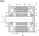
- the metal sheets 22 are made of pure iron, for example, and each have a thickness d in the range from 0.5 ⁇ m to 250 ⁇ m, in particular from 0.5 ⁇ m to 100 ⁇ m. Such thin sheets 22 are produced, for example, by means of a sintering process and are bonded to form a stator core 20 by means of an adhesive and insulating varnish. The task of the adhesive and insulating varnish is to connect the sheets to one another and to isolate them from one another at the same time.
- the laminated stator core 20 of the stator 8 also has a metallic coating 26 on the laminated core back 23. A thickness s of the metallic coating 26 is in the range from 1 mm to 20 mm, in particular from 2 mm to 3 mm.
- FIG 3 shows a schematic representation of a method for producing a stator lamination stack 20.
- a large number of laminations 22, each of which has a maximum thickness d of 250 ⁇ m, in particular 100 ⁇ m, are glued flush to form a stator lamination stack 20 by means of an electrically insulating adhesive.
- the bonded laminated stator core 20 is then pressed together with a force F, for example with the aid of end shields 30, which are part of the rotating electrical machine 2.
- the laminated stator core 20 is pressed together by a tool which is not part of the electric rotating machine 2.
- the laminated core back 23 of the compressed stator laminated core 20 is coated with aluminum by means of cold gas spraying in order to produce a connection between the laminations 22.
- the aluminum particles are sprayed with the aid of a spray device 32 in a rolling manner onto the essentially cylindrical laminated core back 23 of the pressed stator laminated core 20.
- Rolling spraying means that the stator core 20 is rotated about its axis of rotation, while the spray device 32 is moved parallel to the axis of rotation 4, that is, in the axial direction. Since the spray device 32 is not moved in the circumferential direction, it is ensured that the spray particles hit the laminated core back 23 of the laminated stator core 20 at a constant angle.
- at least a part of the end shields 30 is also coated.
- the further version of the laminated stator core 20 in FIG 3 corresponds to the execution in FIG 2 .
- the invention relates to a laminated core for an electrical rotating machine 2.
- the electrical rotating machine 2 have a plurality of metal sheets 22, each of which has a maximum thickness d of 250 ⁇ m, in particular 100 ⁇ m, and is provided by means of a electrically insulating adhesive 34 are glued to form a laminated core, the laminated core being pressed together, the pressed laminated core being at least partially coated with a metallic material for producing a connection between the sheets 22, the coating 26 being made by means of a thermal spraying process.
Landscapes
- Engineering & Computer Science (AREA)
- Manufacturing & Machinery (AREA)
- Power Engineering (AREA)
- Iron Core Of Rotating Electric Machines (AREA)
- Manufacture Of Motors, Generators (AREA)
Priority Applications (2)
| Application Number | Priority Date | Filing Date | Title |
|---|---|---|---|
| EP20154886.4A EP3859953A1 (fr) | 2020-01-31 | 2020-01-31 | Empilement de tôles pour une machine électrique rotative |
| PCT/EP2020/084196 WO2021151560A1 (fr) | 2020-01-31 | 2020-12-02 | Empilement de stratifications pour une machine électrique rotative |
Applications Claiming Priority (1)
| Application Number | Priority Date | Filing Date | Title |
|---|---|---|---|
| EP20154886.4A EP3859953A1 (fr) | 2020-01-31 | 2020-01-31 | Empilement de tôles pour une machine électrique rotative |
Publications (1)
| Publication Number | Publication Date |
|---|---|
| EP3859953A1 true EP3859953A1 (fr) | 2021-08-04 |
Family
ID=69423174
Family Applications (1)
| Application Number | Title | Priority Date | Filing Date |
|---|---|---|---|
| EP20154886.4A Withdrawn EP3859953A1 (fr) | 2020-01-31 | 2020-01-31 | Empilement de tôles pour une machine électrique rotative |
Country Status (2)
| Country | Link |
|---|---|
| EP (1) | EP3859953A1 (fr) |
| WO (1) | WO2021151560A1 (fr) |
Cited By (2)
| Publication number | Priority date | Publication date | Assignee | Title |
|---|---|---|---|---|
| DE102021210756A1 (de) | 2021-09-27 | 2023-03-30 | Siemens Energy Global GmbH & Co. KG | Rotor für eine elektrische rotierende Maschine, elektrische rotierende Maschine, Gondelantrieb und Wasserfahrzeug |
| DE102022117949A1 (de) * | 2022-07-19 | 2024-01-25 | MTU Aero Engines AG | Gehäuseflansch für ein Elektromotorgehäuse eines Elektromotors, eine Anordnung umfassend einen Gehäuseflansch und Statorzähne und Verfahren zur Fertigung eines Gehäuseflansches |
Citations (5)
| Publication number | Priority date | Publication date | Assignee | Title |
|---|---|---|---|---|
| DE102015016584A1 (de) * | 2015-12-19 | 2016-08-18 | Daimler Ag | Verfahren zum Herstellen eines Stators und Stator |
| DE102016203945A1 (de) * | 2016-03-10 | 2017-09-14 | Siemens Aktiengesellschaft | Statoreinrichtung für eine elektrische Maschine und Verfahren zu deren Herstellung |
| EP3373421A1 (fr) | 2017-03-09 | 2018-09-12 | Siemens Aktiengesellschaft | Unité de boîtier pour une machine électrique |
| EP3595148A1 (fr) | 2018-07-13 | 2020-01-15 | Siemens Aktiengesellschaft | Procédé de fabrication d'une couche de matériau et d'une structure de couche de matériau pour une machine rotative dynamoélectrique |
| EP3595132A1 (fr) * | 2018-07-13 | 2020-01-15 | Siemens Aktiengesellschaft | Couche de matériau pour vitesses de rotation élevées et procédé de production |
-
2020
- 2020-01-31 EP EP20154886.4A patent/EP3859953A1/fr not_active Withdrawn
- 2020-12-02 WO PCT/EP2020/084196 patent/WO2021151560A1/fr not_active Ceased
Patent Citations (5)
| Publication number | Priority date | Publication date | Assignee | Title |
|---|---|---|---|---|
| DE102015016584A1 (de) * | 2015-12-19 | 2016-08-18 | Daimler Ag | Verfahren zum Herstellen eines Stators und Stator |
| DE102016203945A1 (de) * | 2016-03-10 | 2017-09-14 | Siemens Aktiengesellschaft | Statoreinrichtung für eine elektrische Maschine und Verfahren zu deren Herstellung |
| EP3373421A1 (fr) | 2017-03-09 | 2018-09-12 | Siemens Aktiengesellschaft | Unité de boîtier pour une machine électrique |
| EP3595148A1 (fr) | 2018-07-13 | 2020-01-15 | Siemens Aktiengesellschaft | Procédé de fabrication d'une couche de matériau et d'une structure de couche de matériau pour une machine rotative dynamoélectrique |
| EP3595132A1 (fr) * | 2018-07-13 | 2020-01-15 | Siemens Aktiengesellschaft | Couche de matériau pour vitesses de rotation élevées et procédé de production |
Cited By (2)
| Publication number | Priority date | Publication date | Assignee | Title |
|---|---|---|---|---|
| DE102021210756A1 (de) | 2021-09-27 | 2023-03-30 | Siemens Energy Global GmbH & Co. KG | Rotor für eine elektrische rotierende Maschine, elektrische rotierende Maschine, Gondelantrieb und Wasserfahrzeug |
| DE102022117949A1 (de) * | 2022-07-19 | 2024-01-25 | MTU Aero Engines AG | Gehäuseflansch für ein Elektromotorgehäuse eines Elektromotors, eine Anordnung umfassend einen Gehäuseflansch und Statorzähne und Verfahren zur Fertigung eines Gehäuseflansches |
Also Published As
| Publication number | Publication date |
|---|---|
| WO2021151560A1 (fr) | 2021-08-05 |
Similar Documents
| Publication | Publication Date | Title |
|---|---|---|
| EP3785355B1 (fr) | Procédé de fabrication d'une couche de matériau et d'une structure de couche de matériau pour une machine rotative dynamoélectrique | |
| DE112012002953B4 (de) | Verfahren zur Herstellung elektrischer Energiewandler sowie damit hergestellte Energiewandler | |
| EP3373421B1 (fr) | Unité de boîtier pour une machine électrique | |
| AT522711A1 (de) | Stator für eine Axialflussmaschine | |
| EP4133571B1 (fr) | Couche de matière pour un paquet de tôles d'une machine électrique | |
| EP3909116B1 (fr) | Agencement de tête d'enroulement pour une machine rotative électrique | |
| EP3821521B1 (fr) | Procédé de fabrication d'un rotor pour une machine à rotation électrique | |
| EP3859953A1 (fr) | Empilement de tôles pour une machine électrique rotative | |
| DE10349442A1 (de) | Elektrische Maschine mit Permanentmagnetrotor und Verfahren zu dessen Herstellung | |
| DE102018205774A1 (de) | Stator für eine elektrische Maschine mit Polschuhen aus Kompositwerkstoff sowie Herstellungsverfahren | |
| EP4222764B1 (fr) | Procédé de fabrication d'une couche de matière pourvue d'au moins un évidement | |
| WO2021032379A1 (fr) | Procédé de fabrication d'un rotor à cage d'écureuil d'une machine asynchrone | |
| DE202012008804U1 (de) | Elektrische Wicklung für elektrische Maschinen und elektrische Maschine mit einer solchen | |
| EP1133815B1 (fr) | Dispositif de commutation, notamment commutateur, et procede pour produire un dispositif de ce type | |
| DE102016207944A1 (de) | Paketsystem für eine elektrische Maschine, elektrische Maschine und Verfahren zur Herstellung des Paketsystems | |
| EP3807982B1 (fr) | Procédé de fabrication d'un dispositif de tête d'enroulement pour une machine rotative électrique | |
| DE102024001782B3 (de) | Verfahren zur Herstellung eines Lötverbundes | |
| EP4531242A1 (fr) | Procédé de fabrication d'un paquet de couches de matériau pour une machine électrique | |
| EP3909113B1 (fr) | Tôle électrique pour une machine électrique et procédé de fabrication d'une tôle électrique | |
| DE102022130312A1 (de) | Rotor-Wellen-Anordnung für eine Elektromaschine sowie Elektromaschine | |
| EP4401290A1 (fr) | Procédé de fabrication d'un rotor à cage d'écureuil | |
| WO2022069291A1 (fr) | Machine électrique et installation | |
| EP3596805B1 (fr) | Machine tournante électrique et son procédé de fabrication | |
| EP4277096A1 (fr) | Rotor d'un moteur à rotor à cage d'écureuil et son procédé de fabrication | |
| WO2023104431A1 (fr) | Procédé de fabrication d'un noyau feuilleté d'une machine électrique |
Legal Events
| Date | Code | Title | Description |
|---|---|---|---|
| PUAI | Public reference made under article 153(3) epc to a published international application that has entered the european phase |
Free format text: ORIGINAL CODE: 0009012 |
|
| STAA | Information on the status of an ep patent application or granted ep patent |
Free format text: STATUS: THE APPLICATION HAS BEEN PUBLISHED |
|
| AK | Designated contracting states |
Kind code of ref document: A1 Designated state(s): AL AT BE BG CH CY CZ DE DK EE ES FI FR GB GR HR HU IE IS IT LI LT LU LV MC MK MT NL NO PL PT RO RS SE SI SK SM TR |
|
| STAA | Information on the status of an ep patent application or granted ep patent |
Free format text: STATUS: THE APPLICATION IS DEEMED TO BE WITHDRAWN |
|
| 18D | Application deemed to be withdrawn |
Effective date: 20220205 |