EP3860103B1 - Bildlesevorrichtung - Google Patents
Bildlesevorrichtung Download PDFInfo
- Publication number
- EP3860103B1 EP3860103B1 EP21154901.9A EP21154901A EP3860103B1 EP 3860103 B1 EP3860103 B1 EP 3860103B1 EP 21154901 A EP21154901 A EP 21154901A EP 3860103 B1 EP3860103 B1 EP 3860103B1
- Authority
- EP
- European Patent Office
- Prior art keywords
- apparatus body
- rotation axis
- center
- document
- viewed
- Prior art date
- Legal status (The legal status is an assumption and is not a legal conclusion. Google has not performed a legal analysis and makes no representation as to the accuracy of the status listed.)
- Active
Links
Images






Classifications
-
- H—ELECTRICITY
- H04—ELECTRIC COMMUNICATION TECHNIQUE
- H04N—PICTORIAL COMMUNICATION, e.g. TELEVISION
- H04N1/00—Scanning, transmission or reproduction of documents or the like, e.g. facsimile transmission; Details thereof
- H04N1/00519—Constructional details not otherwise provided for, e.g. housings, covers
- H04N1/00525—Providing a more compact apparatus, e.g. sheet discharge tray in cover
-
- H—ELECTRICITY
- H04—ELECTRIC COMMUNICATION TECHNIQUE
- H04N—PICTORIAL COMMUNICATION, e.g. TELEVISION
- H04N1/00—Scanning, transmission or reproduction of documents or the like, e.g. facsimile transmission; Details thereof
- H04N1/00127—Connection or combination of a still picture apparatus with another apparatus, e.g. for storage, processing or transmission of still picture signals or of information associated with a still picture
- H04N1/00326—Connection or combination of a still picture apparatus with another apparatus, e.g. for storage, processing or transmission of still picture signals or of information associated with a still picture with a data reading, recognizing or recording apparatus, e.g. with a bar-code apparatus
-
- H—ELECTRICITY
- H04—ELECTRIC COMMUNICATION TECHNIQUE
- H04N—PICTORIAL COMMUNICATION, e.g. TELEVISION
- H04N1/00—Scanning, transmission or reproduction of documents or the like, e.g. facsimile transmission; Details thereof
- H04N1/00519—Constructional details not otherwise provided for, e.g. housings, covers
- H04N1/00562—Supporting the apparatus as a whole, e.g. stands
-
- H—ELECTRICITY
- H04—ELECTRIC COMMUNICATION TECHNIQUE
- H04N—PICTORIAL COMMUNICATION, e.g. TELEVISION
- H04N1/00—Scanning, transmission or reproduction of documents or the like, e.g. facsimile transmission; Details thereof
- H04N1/00519—Constructional details not otherwise provided for, e.g. housings, covers
-
- H—ELECTRICITY
- H04—ELECTRIC COMMUNICATION TECHNIQUE
- H04N—PICTORIAL COMMUNICATION, e.g. TELEVISION
- H04N1/00—Scanning, transmission or reproduction of documents or the like, e.g. facsimile transmission; Details thereof
- H04N1/00519—Constructional details not otherwise provided for, e.g. housings, covers
- H04N1/00525—Providing a more compact apparatus, e.g. sheet discharge tray in cover
- H04N1/00535—Providing a more compact apparatus, e.g. sheet discharge tray in cover using rotatably mounted or foldable components
-
- H—ELECTRICITY
- H04—ELECTRIC COMMUNICATION TECHNIQUE
- H04N—PICTORIAL COMMUNICATION, e.g. TELEVISION
- H04N1/00—Scanning, transmission or reproduction of documents or the like, e.g. facsimile transmission; Details thereof
- H04N1/00519—Constructional details not otherwise provided for, e.g. housings, covers
- H04N1/00551—Top covers or the like
-
- H—ELECTRICITY
- H04—ELECTRIC COMMUNICATION TECHNIQUE
- H04N—PICTORIAL COMMUNICATION, e.g. TELEVISION
- H04N1/00—Scanning, transmission or reproduction of documents or the like, e.g. facsimile transmission; Details thereof
- H04N1/00519—Constructional details not otherwise provided for, e.g. housings, covers
- H04N1/00559—Mounting or support of components or elements
-
- H—ELECTRICITY
- H04—ELECTRIC COMMUNICATION TECHNIQUE
- H04N—PICTORIAL COMMUNICATION, e.g. TELEVISION
- H04N1/00—Scanning, transmission or reproduction of documents or the like, e.g. facsimile transmission; Details thereof
- H04N1/00567—Handling of original or reproduction media, e.g. cutting, separating, stacking
- H04N1/0057—Conveying sheets before or after scanning
- H04N1/00599—Using specific components
- H04N1/00602—Feed rollers
-
- H—ELECTRICITY
- H04—ELECTRIC COMMUNICATION TECHNIQUE
- H04N—PICTORIAL COMMUNICATION, e.g. TELEVISION
- H04N1/00—Scanning, transmission or reproduction of documents or the like, e.g. facsimile transmission; Details thereof
- H04N1/00567—Handling of original or reproduction media, e.g. cutting, separating, stacking
- H04N1/0057—Conveying sheets before or after scanning
- H04N1/00599—Using specific components
- H04N1/00615—Guiding elements, e.g. plates
-
- H—ELECTRICITY
- H04—ELECTRIC COMMUNICATION TECHNIQUE
- H04N—PICTORIAL COMMUNICATION, e.g. TELEVISION
- H04N1/00—Scanning, transmission or reproduction of documents or the like, e.g. facsimile transmission; Details thereof
- H04N1/00567—Handling of original or reproduction media, e.g. cutting, separating, stacking
- H04N1/00628—Separating, e.g. preventing feeding of two sheets at a time
-
- H—ELECTRICITY
- H04—ELECTRIC COMMUNICATION TECHNIQUE
- H04N—PICTORIAL COMMUNICATION, e.g. TELEVISION
- H04N1/00—Scanning, transmission or reproduction of documents or the like, e.g. facsimile transmission; Details thereof
- H04N1/00795—Reading arrangements
Definitions
- the present disclosure relates to an image reading apparatus for reading images on documents.
- Some image reading apparatuses such as scanners have a sheet transport path provided in the housing of the apparatus body, and the position of the sheet transport path can be changed between a first position in which the sheet transport path is tilted with respect to the horizontal direction and a second position in which the sheet transport path is closer to the horizontal position than the first position, for example, as described in JP-T-2009-527143 .
- the apparatus body is turnable with respect to a support base and the position of the apparatus body with respect to the support base can be maintained using a latch mechanism.
- the image reading apparatus in JP-T-2009-527143 has no special means for stabilizing the apparatus body in such a case.
- US 2007/188818 discloses a document imaging apparatus for recording document data that has an imager body that has an image data transformation apparatus and a paper feed apparatus for urging a document sheet along a paper path from a paper feed input source, past the image data transformation apparatus, to an output slot.
- the imager body is pivotably coupled to a support pedestal for adjusting the tilt angle of the imager body to one of a plurality of tilt angle positions.
- an image reading apparatus as defined in claim 1.
- the scanner 1 is a document scanner that reads a document while transporting the document with respect to a apparatus body with respect to the support section, in which the position of the apparatus body can be switched between a first position in which the apparatus body is not in use and a second position in which the apparatus body reads a document using the reader, and in which a projected area of the apparatus body on the mounting surface is larger than that in the first position, and the center of gravity of the apparatus body is lower than or equal to a rotation axis center of the apparatus body in a vertical direction viewed in a rotation axis direction of the apparatus body when the apparatus body is in the first position or in the second position.
- the center of gravity of the apparatus body is lower than or equal to a rotation axis center of the apparatus body in a vertical direction viewed in a rotation axis direction of the apparatus body when the apparatus body is in the first position or in the second position. Consequently, the apparatus body is stable with respect to the support section.
- the center of gravity of the apparatus body when the apparatus body is in the first position, may overlap with the rotation axis center of the apparatus body viewed in the rotation axis direction of the apparatus body. According to the aspect, when the apparatus body is in the first position, the center of gravity of the apparatus body corresponds to the rotation axis center of the apparatus body viewed in the rotation axis direction of the apparatus body, and thus no rotation moment is produced in the apparatus body when the apparatus body is in the first position, enabling more stable apparatus body with respect to the support section.
- the apparatus body may include a feed tray configured to support the document to be fed, and a discharge tray configured to support the document that is read and discharged, in which the feed tray and the discharge tray are configured to be switched between an open state and a closed state with respect to the apparatus body, the apparatus body is configured to be switched to a third position in which the apparatus body reads the document using the reader and in which a projected area of the apparatus body on the mounting surface is larger than that in the second position, and the center of gravity of the apparatus body is lower than the rotation axis center of the apparatus body in the vertical direction viewed in the rotation axis direction of the apparatus body when the apparatus body is in the second position or in the third position regardless of an open/close state of the feed tray and the discharge tray.
- the center of gravity of the apparatus body is lower than the rotation axis center of the apparatus body in the vertical direction viewed in the rotation axis direction of the apparatus body when the apparatus body is in the second position or in the third position regardless of an open/close state of the feed tray and the discharge tray. Consequently, the apparatus body is stable with respect to the support section when the apparatus body is in the second position or in the third position regardless of an open/close state of the feed tray and the discharge tray.
- the apparatus body may include a pair of transport rollers disposed upstream of the reader in a straight document transport path on which the document is transported, the pair of transport rollers being configured to transport the document downstream, a feed roller disposed upstream of the pair of transport rollers in the document transport path, the feed roller being configured to feed the document downstream, a pair of discharge rollers disposed downstream of the reader, the pair of discharge rollers being configured to discharge the document, a first motor that is a drive source for the pair of transport rollers and the pair of discharge rollers, and a second motor that is a drive source for the feed roller, in which the apparatus body is configured to be switched to a third position in which the apparatus body reads a document using the reader and in which a projected area of the apparatus body on the mounting surface is larger than that in the second position, and the first motor and the second motor are lower than the rotation axis center of the apparatus body in the vertical direction viewed in the rotation axis direction of the apparatus body when the apparatus body
- the motors are heavy objects and are components that greatly affect the center of gravity of the apparatus.
- the first motor and the second motor are lower than the rotation axis center of the apparatus body in the vertical direction viewed in the rotation axis direction of the apparatus body when the apparatus body is in the second position or in the third position. Accordingly, the structure in which the center of gravity of the apparatus body in the vertical direction is equal to or lower than the rotation axis center of the apparatus body can be readily provided.
- the apparatus body may include a separation roller configured to nip and separate a document with the feeding roller therebetween, a background plate disposed at a position facing the reader, the background plate being configured to be switched between a facing state in which the background plate faces the reader and a non-facing state in which the background plate does not face the reader, a third motor that is a power source for switching the state of the background plate, and a fourth motor that is a drive source for the separation roller, in which the fourth motor is higher than the rotation axis center of the apparatus body in the vertical direction viewed in the rotation axis direction of the apparatus body when the apparatus body is in the second position or in the third position, and the third motor is lower than the rotation axis center of the apparatus body in the vertical direction viewed in the rotation axis direction of the apparatus body when the apparatus body is in the second position or in the third position.
- three motors of the four motors that is, the first motor, the second motor, the third motor, and the fourth motor are vertically lower than the rotation axis center of the apparatus body viewed in the rotation axis direction of the apparatus body. Accordingly, the structure in which the center of gravity of the apparatus body in the vertical direction is equal to or lower than the rotation axis center of the apparatus body can be readily provided.
- the pair of transport rollers and the pair of discharge rollers may be lower than the rotation axis center of the apparatus body in the vertical direction viewed in the rotation axis direction of the apparatus body when the apparatus body is in the first position.
- the pair of transport rollers and the pair of discharge rollers are heavy objects and are components that greatly affect the center of gravity of the apparatus.
- the pair of transport rollers and the pair of discharge rollers are lower than the rotation axis center of the apparatus body in the vertical direction viewed in the rotation axis direction of the apparatus body when the apparatus body is in the first position, and thus the structure in which the center of gravity of the apparatus body in the vertical direction is equal to or lower than the rotation axis center of the apparatus body can be readily provided.
- the apparatus body may include a substrate on which electronic components are mounted, the apparatus body is configured to be switched to a third position in which the apparatus body reads a document using the reader, and in which a projected area of the apparatus body on the mounting surface is larger than that in the second position, and the substrate is lower than the rotation axis center of the apparatus body in the vertical direction viewed in the rotation axis direction of the apparatus body when the apparatus body is in the second position or in the third position.
- the substrate on which electronic components are mounted is a heavy object and is a component that greatly affect the center of gravity of the apparatus.
- the substrate is lower than the rotation axis center of the apparatus body in the vertical direction viewed in the rotation axis direction of the apparatus body when the apparatus body is in the second position or in the third position, and thus the structure in which the center of gravity of the apparatus body in the vertical direction is equal to or lower than the rotation axis center of the apparatus body can be readily provided.
- An image reading apparatus includes a support section in contact with a mounting surface on which the apparatus is mounted, an apparatus body including a reader configured to read a document, the apparatus body configured to be turnable with respect to the support section for position change, and a position holding section for holding a position of the apparatus body with respect to the support section, in which the apparatus body is configured to be switched between two different positions, and the center of gravity of the apparatus body in the two positions is lower than or equal to a rotation shaft of the apparatus body in a vertical direction viewed in the rotation axis direction of the apparatus body.
- the center of gravity of the apparatus body in the two positions is lower than a rotation shaft of the apparatus body in the vertical direction viewed in the rotation axis direction of the apparatus body. Consequently, the apparatus body is stable with respect to the support section.
- the center of gravity of the apparatus body may overlaps with the rotation shaft of the apparatus body viewed in the rotation axis direction of the apparatus body when the apparatus body is in one of the two positions, and the center of gravity of the apparatus body may be lower than the center of gravity in the one position when the apparatus body is in the other position of the two positions.
- the apparatus body may include a feed tray configured to support the document to be fed, and a discharge tray configured to support the document that is read and discharged, in which the feed tray and the discharge tray are configured to be switched between an open state and a closed state with respect to the apparatus body.
- the center of gravity of the apparatus body may be lower than the rotation axis center of the apparatus body viewed in the rotation axis direction of the apparatus body when the apparatus body is in the one position with the feed tray and the discharge tray being opened or when the apparatus body is in the other position with the feed tray and the discharge tray being opened.
- the center of gravity of the apparatus body may be lower than the rotation axis center of the apparatus body viewed in the rotation axis direction of the apparatus body when the apparatus body is in the one position with the feed tray and the discharge tray being closed or when the apparatus body is in the other position with the feed tray and the discharge tray being closed.
- the center of gravity of the apparatus body may move forward when the apparatus body is in the one position or in the other position and both of the feed tray and the discharge tray are opened from the closed state.
- the apparatus body in a structure in which the center of gravity of the apparatus body moves forward when the apparatus body is in the one position or in the other position and both of the feed tray and the discharge tray are opened from a closed state, the apparatus body is stable with respect to the support section.
- An image reading apparatus includes a support section in contact with a mounting surface on which the apparatus is mounted, an apparatus body including a reader configured to read a document, the apparatus body being configured to be turnable with respect to the support section for position change, and a position holding section for holding a position of the apparatus body with respect to the support section, in which the apparatus body is configured to be switched between a first position in which the apparatus body does not read a document using the reader and a second position in which the apparatus body reads a document using the reader, the second position turned from the first position, and the center of gravity of the apparatus body is lower than or equal to a rotation axis center of the apparatus body in a vertical direction viewed in a rotation axis direction of the apparatus body when the apparatus body is in the first position or in the second position.
- the center of gravity of the apparatus body is lower than or equal to a rotation axis center of the apparatus body viewed in a rotation axis direction of the apparatus body when the apparatus body is in the first position or in the second position. Consequently, the apparatus body is stable with respect to the support section.
- the apparatus body may be configured to be switched to a third position in which the apparatus body reads a document using the reader and in which the apparatus body is turned from the second position in the same direction as the direction in which the apparatus body is turned from the first position to the second position, and the center of gravity of the apparatus body is lower than the rotation axis center of the apparatus body in the vertical direction viewed in the rotation axis direction of the apparatus body when the apparatus body is in the third position.
- the apparatus body may include a pair of transport rollers disposed upstream of the reader in a straight document transport path on which a document is transported, the pair of transport rollers being configured to transport the document downstream, a feed roller disposed upstream of the pair of transport rollers in the document transport path, the feed roller being configured to feed a document downstream, a pair of discharge rollers disposed downstream of the reader, the pair of discharge rollers being configured to discharge a read document, a first motor that is a drive source for at least one of the pair of transport rollers and the pair of discharge rollers, and a second motor that is a drive source for the feed roller, in which a drive shaft of the first motor is lower than the rotation axis center of the apparatus body in the vertical direction viewed in the rotation axis direction of the apparatus body when the apparatus body is in the first position, in the second position, or in the third position.
- a drive shaft of the second motor may be higher than the rotation axis center of the apparatus body in the vertical direction viewed in the rotation axis direction of the apparatus body when the apparatus body is in the first position, and the drive shaft of the second motor may be lower than the rotation axis center of the apparatus body in the vertical direction viewed in the rotation axis direction of the apparatus body when the apparatus body is in the second position or in the third position.
- the apparatus body may include a background plate disposed at a position facing the reader, the background plate being configured to be switched between a facing state in which the background plate faces the reader and a non-facing state in which the background plate does not face the reader, and a third motor that is a power source for switching the state of the background plate, in which a drive shaft of the third motor is lower than the rotation axis center of the apparatus body in the vertical direction viewed in the rotation axis direction of the apparatus body when the apparatus body is in the first position, in the second position, or in the third position.
- the apparatus body may include a separation roller configured to nip and separate a document with the feeding roller therebetween, and a fourth motor that is a drive source for the separation roller, in which a drive shaft of the fourth motor is higher than the rotation axis center of the apparatus body in the vertical direction viewed in the rotation axis direction of the apparatus body when the apparatus body is in the first position, the second position, or in the third position.
- the apparatus body may include a substrate on which electronic components configured to control the reader are mounted, in which part of the substrate is higher than the rotation axis center of the apparatus body in the vertical direction viewed in the rotation axis direction of the apparatus body when the apparatus body is in the first position, and the substrate is lower than the rotation axis center of the apparatus body in the vertical direction viewed in the rotation axis direction of the apparatus body when the apparatus body is in the second position or in the third position.
- An image reading apparatus includes a support section in contact with a mounting surface on which the apparatus is mounted, an apparatus body including a reader configured to read a document, the apparatus body configured to be turnable with respect to the support section for position change, and a position holding section for holding a position of the apparatus body with respect to the support section, in which the apparatus body is configured to be switched between two different positions in which the reader performs a document reading operation, and the center of gravity of the apparatus body is lower than a rotation shaft of the apparatus body viewed in the rotation axis direction of the apparatus body when the apparatus body is in one of the two positions.
- the center of gravity of the apparatus body in the vertical is lower than a rotation axis center of the apparatus body viewed in the rotation axis direction of the apparatus body. Consequently, the apparatus body is stable with respect to the support section.
- a scanner 1 that can read at least one of the front side and the back side of a document will be described as an example image reading apparatus.
- the scanner 1 is a document scanner that reads a document while transporting the document with respect to a reader.
- an X-axis direction denotes an apparatus width direction and also denotes a document width direction.
- a rotation axis direction of an apparatus body 2 which will be described below, is parallel to the X-axis direction.
- a Y-axis direction denotes an apparatus depth direction and also denotes a direction in a horizontal direction.
- a Z-axis direction denotes a direction in a vertical direction that is orthogonal to the X-axis direction and the Y-axis direction.
- a V-axis direction is parallel to a document transport path, which will be described below, and an angle, especially an angle that is formed by the V-axis and the Y-axis varies depending on the position of the apparatus.
- a +Y direction denotes a direction from an apparatus rear toward an apparatus front
- a -Y direction denotes a direction from the apparatus front toward the apparatus rear.
- the left denotes a +X direction
- the right denotes a -X direction.
- a direction (+V direction) in which a document is transported may be referred to as "downstream” and the opposite direction (-V direction) may be referred to as "upstream”.
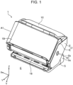
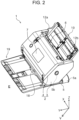
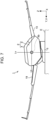
- the scanner 1 in FIG. 1 to FIG. 4 includes an apparatus body 2 and a support section 5 that supports the apparatus body 2 such that the apparatus body 2 can be turned.
- the apparatus body 2 includes a lower unit 3 and an upper unit 4.
- the upper unit 4 can be turned about a rotation shaft (not illustrated) with respect to the lower unit 3 so as to be opened and closed.
- the upper unit 4 can be opened toward the apparatus front so as to expose a document transport path, which will be described below.
- the lower unit 3 in the apparatus body 2 can be turned about a rotation shaft 5b with respect to arm sections 5a of the support section 5, thereby the position of the lower unit 3 can be changed.
- the arm sections 5a are each disposed on both sides of the apparatus body in the X-axis direction, and the apparatus body 2 is supported by the support section 5 on both sides in the X-axis direction.
- Straight line A1 in FIG. 1 denotes an axis center line of the rotation shaft 5b and is a rotation axis of the apparatus body 2.
- the rotation axis A1 according to the embodiment is a straight line that is parallel to the X axis.
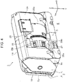
- An outer shell of the lower unit 3 has a first housing 24 and a second housing 25 as illustrated in FIG. 4 .
- the second housing 25 has an arch portion 25a that has a shape along a rotational trajectory of the lower unit 3.
- a rack 26 is disposed in the arch portion 25a and engages with a pinion gear 28 disposed in the support section 5 as illustrated in FIG. 8 to FIG. 10 .
- the pinion gear 28 receives a rotational load from a damper mechanism (not illustrated), and the rotational load reduces the turning speed when the lower unit 3 is turned, that is, when the position of the apparatus body 2 is changed.
- the apparatus body 2 of the scanner 1 can be held in one of three positions by a position holding section, which will be described below.
- the three positions include two positions in which the apparatus body 2 is held for document reading and one position in which the apparatus body 2 is not in use.
- the positions illustrated in FIG. 1 , FIG. 2 , and FIG. 6 to FIG. 9 are used when the apparatus body 2 is held for document reading, whereas the position illustrated in FIG. 3 , FIG. 4 , and FIG. 10 is used when the apparatus body 2 is not in use.
- the position illustrated in FIG. 3 , FIG. 4 , and FIG. 10 is an example first position.
- the positions for document reading include the position illustrated in FIG. 1 , FIG. 2 , FIG. 6 , and FIG.
- a projected area of the scanner 1 on a mounting surface E is the smallest when the apparatus body 2 is in the first position, and more specifically, a space occupied in the Y-axis direction is the smallest.
- a projected area of the scanner 1 on the mounting surface E is the largest when the apparatus body 2 is in the third position.
- the first position and the second position of the apparatus body 2 are example different two positions, and when one position is the first position, the other position is the second position, or when one position is the second position, the other position is the first position.
- the first position and the third position of the apparatus body 2 are example two different positions, and when one position is the first position, the other position is the third position, or when one position is the third position, the other position is the first position.
- the second position and the third position of the apparatus body 2 are example two different positions, and when one position is the second position, the other position is the third position, or when one position is the third position, the other position is the second position.
- the positions of the apparatus body 2 can be detected by a position detector (not illustrated).
- the position holding section includes a first recessed portion 29a, a second recessed portion 29b, and a third recessed portion 29c illustrated in FIG. 4 and an advancing/retracting unit 8 illustrated in FIG. 5 .
- the first recessed portion 29a, the second recessed portion 29b, and the third recessed portion 29c illustrated in FIG. 4 are provided at intervals along a circumference of the arch portion 25a of the second housing 25.
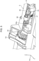
- the advancing/retracting unit 8 illustrated in FIG. 5 includes a base section 35, a slider unit 36, a spring 37, and an operation lever 27 (see FIG. 4 ).
- the slider unit 36 is disposed such that the position of the slider unit 36 can be changed in an advancing/retracting direction in the base section 35 with respect to the arch portion 25a.
- the spring 37 presses the slider unit 36 against the arch portion 25a.
- the operation lever 27 is used for the slider unit 36 to be retracted away from the arch portion 25a against the spring force of the spring 37.
- the slider unit 36 includes a driven roller 38.
- the driven roller 38 is a freely rotatable roller and can be brought into contact with the surface of the arch portion 25a illustrated in FIG. 4 when the position of the apparatus body 2 is changed, and can be fitted into one of the first recessed portion 29a, the second recessed portion 29b, and the third recessed portion 29c to hold the position of the apparatus body 2. More specifically, the driven roller 38 is fitted into the first recessed portion 29a illustrated in FIG. 4 to hold the apparatus body 2 in the first position, is fitted into the second recessed portion 29b in FIG. 4 to hold the apparatus body 2 in the second position, and is fitted into the third recessed portion 29c in FIG. 4 to hold the apparatus body 2 in the third position.
- the operation lever 27 in FIG. 4 is operated to release a position holding state of the apparatus body 2.
- the slider unit 36 is moved downward, the driven roller 38 is retracted away from the corresponding recessed portion, and the apparatus body 2 becomes freely rotatable, thereby enabling position change.
- the upper unit 4 includes a front cover 19 that functions as a "discharge tray” as illustrated in FIG. 1 to FIG. 4 .
- the lower unit 3 includes a top cover 10 that functions as a "feed tray”.
- the front cover 19 can be turned with respect to the upper unit 4 to a closed position as illustrated in FIG. 1 , FIG. 3 , FIG. 4 . and FIG. 10 or to an open position as illustrated in FIG. 2 , and FIG. 6 to FIG. 9 .
- the front cover 19 When the front cover 19 is open, it functions as a discharge tray for receiving a document that is read and discharged.
- the upper unit 4 has an operation panel 7 on an upper surface as illustrated in FIG. 2 .
- a user interface for setting various settings for reading, for executing a reading operation, for displaying reading setting contents, or the like can be implemented.
- the operation panel 7 according to the embodiment is a touch panel through which both of a displaying operation and an inputting operation can be performed.
- the operation panel 7 functions as an operation section for performing various operations and also functions as a display section for displaying various kinds of information.
- the operation panel 7 is exposed by opening the front cover 19.
- the top cover 10 that is provided to the lower unit 3 can be turned with respect to the lower unit 3 to a closed position as illustrated in FIG. 1 , FIG. 3 , FIG. 4 , and FIG. 10 or to an open position as illustrated in FIG. 2 , and FIG. 6 to FIG. 9 .
- the top cover 10 When the top cover 10 is open, it functions as a feed tray for supporting a document to be fed.
- edge guides 12a and 12b guide side edges of a document.
- a feed slot 6 that is contiguous to the inside of the apparatus body 2 is provided in an upper portion of the apparatus body 2.
- a document mounted on the top cover 10 is fed from the feed slot 6 into the apparatus body 2.
- a straight document transport path T2 illustrated in FIG. 8 is a document transport path that is used when the apparatus body 2 is in the second position.
- a straight document transport path T3 illustrated in FIG. 9 is a document transport path that is used when the apparatus body 2 is in the third position.
- a straight document transport path T1 illustrated in FIG. 10 is a document transport path that is used when the apparatus body 2 is in the first position. It should be noted that the first position of the apparatus body 2 illustrated in FIG. 10 is a position in which the apparatus body 2 is not in use, and no document is actually transported in this position. The document transport path is closest to the vertical when the apparatus body 2 is in the first position illustrated in FIG.
- the document transport paths T1, T2, and T3 may be referred to as a document transport path T when it is not particularly necessary to distinguish the individual document transport paths.
- the document transport path T is a substantially straight document transport path defined by the lower unit 3 and the upper unit 4.
- a transport path is defined by the lower unit 3 and the upper unit 4 from a roller pair that consists of a feed roller 14 and a separation roller 15 to a pair of transport rollers 16.
- the top cover 10 is disposed most upstream of the document transport path T.
- the feed roller 14, which feeds documents mounted on the top cover 10 downstream, and the separation roller 15, which nips and separates the documents with the feed roller 14 therebetween are disposed downstream of the top cover 10 on the document transport path T.
- the feed roller 14 comes into contact with the lowermost document of documents mounted on the top cover 10. Accordingly, when a plurality of sheets of documents is mounted on the top cover 10, the documents are sequentially fed from the lowermost document downstream.
- the feed roller 14 rotates in the counterclockwise direction in FIG. 8 in response to a rotation torque from a second motor 44.
- the rotation torque for rotating the separation roller 15 in the counterclockwise direction in FIG. 8 is transmitted from a fourth motor 45 through a torque limiter (not illustrated).
- the pair of transport rollers 16, a reader 20 for reading document images, and a pair of discharge rollers 17 are disposed downstream of the feeding roller 14.
- the pair of transport rollers 16 includes a transport driving roller 16a that is driven by a first motor 43 and a transport driven roller 16b that is driven to rotate.
- a document that is nipped by the feed roller 14 and the separation roller 15 is fed downstream, the document is nipped by the pair of transport rollers 16, and is transported to a position at which the document faces an upper sensor unit 20A and a lower sensor unit 20B, which are disposed downstream of the pair of transport rollers 16.
- the reader 20 includes the upper sensor unit 20A and the lower sensor unit 20B.
- the upper sensor unit 20A is disposed in the upper unit 4 and above the document transport path T
- the lower sensor unit 20B is disposed in the lower unit 3 and below the document transport path T.
- the upper sensor unit 20A includes a sensor module 21A
- the lower sensor unit 20B includes a sensor module 21B.
- the sensor modules 21A and 21B function as a contact image sensor (CIS) module (CISM).
- CIS contact image sensor
- the sensor module 21A that is disposed above the document transport path T reads an upper surface of a document
- the sensor module 21B that is disposed below the document transport path T reads a lower surface of a document.
- a document reading surface (not illustrated) implemented by the upper sensor unit 20A and a document reading surface (not illustrated) implemented by the lower sensor unit 20B are parallel to the document transport path T.
- the upper sensor unit 20A includes a background plate 22A that is disposed to face the sensor module 21B in the lower sensor unit 20B whereas the lower sensor unit 20B includes a background plate 22B that is disposed to face the sensor module 21A in the upper sensor unit 20A.
- the background plates 22A and 22B are used for shading correction and function as reference plates that are read by the respective sensor modules that face to each other.
- the background plates are, for example, resin plates of white, gray, black, or the like or metal plates coated in white, gray, black or the like.
- the background plates 22A and 22B can be turned by the power of a third motor 46, and turning the background plates 22A and 22B switches them between a facing state in which the background plates 22A and 22B face the respective facing sensor modules as illustrated in the solid lines and a non-facing state in which the facing state is released as illustrated in the chain double-dashed lines.
- the background plates 22A and 22B are, for example, white, and in such a case white reference value can be acquired in the facing state and a black reference value can be acquired in the non-facing state.
- the pair of discharge rollers 17 includes a discharge driving roller 17a that is driven by the first motor 43 and a discharge driven roller 17b that is driven to rotate.
- a main board 47 is a substrate on which electronic components are mounted.
- the main board 47 functions as a controller for performing various control processes in the scanner 1 such as a reading control process for the reader 20, a feeding control process, a transport control process, and the like using the electronic components.
- the main board 47 is disposed in a position along the document transport path T.
- the second housing 25 which functions as the outer shell of the lower unit 3, includes the arch portion 25a along a rotational trajectory of the lower unit 3 at a position facing the support section 5 and the main board 47 that is disposed in a space 25d inside the arch portion 25a. This structure enables an effective use of the space inside the housing, reducing the size of the apparatus.
- FIG. 6 and FIG. 7 illustrate the front cover 19, which function as a discharge tray, and the top cover 10, which functions as a feed tray, in an open state.
- Line Lh is a horizontal line extending through an axis center position of the rotation shaft 5b
- line Lv is a vertical line extending through an axis center position of the rotation shaft 5b.
- FIG. 8 to FIG. 13 illustrate horizontal line Lh and vertical line Lv.
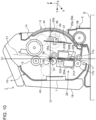
- FIG. 8 illustrates the center of gravity G2 of the apparatus body 2 when the apparatus body 2 is in the second position and the front cover 19 and the top cover 10 are open.
- the second position is used in a state in which a reading operation is performed using the reader 20 or the reader 20 is used.
- the center of gravity G2 is lower than horizontal line Lh in the vertical direction and is closer to the apparatus front side than vertical line Lv in the horizontal direction (Y-axis direction) as illustrated in FIG. 8 when viewed in the rotation axis direction of the apparatus body 2.
- the center of gravity G2 is lower than the rotation axis center of the apparatus body 2 in the vertical direction. It should be noted that the center of gravity G2 may be lower than the rotation shaft 5b of the apparatus body 2 in the vertical direction.
- the center of gravity G2a of the apparatus body 2 is a position when the apparatus body 2 is in the second position and the front cover 19 and the top cover 10 are not open but closed.
- the center of gravity G2a is lower than horizontal line Lh in the vertical direction and is on vertical line Lv in the horizontal direction (Y-axis direction) as illustrated in FIG. 8 when viewed from the rotation axis direction of the apparatus body 2.
- the center of gravity G2a is lower than the rotation axis center of the apparatus body 2 in the vertical direction. It should be noted that the center of gravity G2a may be lower than the rotation shaft 5b of the apparatus body 2 in the vertical direction.
- FIG. 9 illustrates the center of gravity G3 of the apparatus body 2 when the apparatus body 2 is in the third position and the front cover 19 and the top cover 10 are open.
- the third position is used in a state in which a document reading operation is performed using the reader 20 or the reader 20 is used.
- the center of gravity G3 is lower than horizontal line Lh in the vertical direction and is closer to the apparatus front side than vertical line Lv in the horizontal direction (Y-axis direction) when viewed in the rotation axis direction of the apparatus body 2 as illustrated in FIG. 9 .
- the center of gravity G3 is lower than the rotation axis center of the apparatus body 2 in the vertical direction. It should be noted that the center of gravity G3 may be lower than the rotation shaft 5b of the apparatus body 2 in the vertical direction.
- the center of gravity G3a of the apparatus body 2 is a position when the apparatus body 2 is in the third position and the front cover 19 and the top cover 10 are not open but closed.
- the center of gravity G3a is lower than horizontal line Lh in the vertical direction and is closer to the apparatus rear side than vertical line Lv in the horizontal direction (Y-axis direction) when viewed in the rotation axis direction of the apparatus body 2 as illustrated in FIG. 9 .
- the center of gravity G3a is lower than the rotation axis center of the apparatus body 2 in the vertical direction. It should be noted that the center of gravity G3a may be lower than the rotation shaft 5b of the apparatus body 2 in the vertical direction.
- FIG. 10 illustrates the center of gravity G1 of the apparatus body 2 when the apparatus body 2 is in the first position and the front cover 19 and the top cover 10 are closed.
- the first position is used in a state in which a document reading operation is not performed using the reader 20, in a state in which the front cover 19, which function as a discharge tray, and the top cover 10, which functions as a feed tray, are closed, or in a state in which the reader 20 is not in use.
- the center of gravity G1 is within the area of the rotation shaft 5b of the apparatus body 2 viewed in the rotation axis direction of the apparatus body 2 as illustrated in FIG. 10 .
- the center of gravity G1 may be on horizontal line Lh in the vertical direction, and may be on the rotation axis center of the apparatus body 2 on vertical line Lv in the horizontal direction (Y-axis direction). It should be noted that the center of gravity G1 may be any point within the area of the rotation shaft 5b and equal to or lower than the rotation axis center in the vertical direction.
- the first position of the apparatus body 2 is used when the apparatus body 2 is not in use.
- the front cover 19 and the top cover 10 are not open. Accordingly, in FIG. 10 , the center of gravity of the apparatus body 2 in the state in which the apparatus body 2 is in the first position and the front cover 19 and the top cover 10 are open is not illustrated.
- the center of gravity of the apparatus body 2 in the X-axis direction is not illustrated, the center of gravity of the apparatus body 2 is at a central point in the X-axis direction regardless of the position of the apparatus body 2 and regardless of an open/close state of the front cover 19 and the top cover 10.
- the center of gravity of the apparatus body 2 in the vertical direction viewed in the rotation axis direction of the apparatus body 2 is equal to or lower than the rotation axis center of the apparatus body 2 at least when the apparatus body 2 is in the first position (see FIG. 10 ) or in the second position (see FIG. 8 ), enabling the stable apparatus body 2 with respect to the support section 5.
- the center of gravity of the apparatus body 2 when the apparatus body 2 is in the third position (see FIG. 9 ), the center of gravity of the apparatus body 2 is equal to or lower than the rotation axis center of the apparatus body 2 in the vertical direction.
- the center of gravity of the apparatus body 2 at all positions during the position change of the apparatus body 2 between the first position ( FIG. 10 ) and the third position ( FIG. 9 ), the center of gravity of the apparatus body 2 is equal to or lower than the rotation axis center of the apparatus body in the vertical direction.
- This structure is not limited to this example and the center of gravity of the apparatus body 2 may be temporarily in a position higher than the rotation axis center of the apparatus body 2 in the vertical direction while the apparatus body 2 is changing the position.
- the center of gravity of the apparatus body 2 in the vertical direction viewed in the rotation axis direction of the apparatus body 2 is lower than the rotation axis center of the apparatus body 2 when the apparatus body 2 is in the second position (see FIG. 8 ) or in the third position (see FIG. 9 ).
- the center of gravity of the apparatus body 2 corresponds to the rotation axis center of the apparatus body 2.
- the center of gravity of the apparatus body 2 in the vertical direction may correspond to the rotation axis center of the apparatus body 2 when the apparatus body 2 is in the second position (see FIG. 8 ) or in the third position (see FIG. 9 ), or may be lower than the rotation axis center of the apparatus body 2 when the apparatus body 2 is in the first position (see FIG. 10 ).
- the apparatus body 2 can be positioned in one of two different positions, and in each of the two positions, the center of gravity of the apparatus body 2 in the vertical direction is equal to or lower than the rotation shaft 5b of the apparatus body 2 viewed in the rotation axis direction of the apparatus body 2.
- the two different positions may be any two positions of the first position, the second position, and the third position.
- the center of gravity of the apparatus body 2 viewed in the rotation axis direction of the apparatus body 2 corresponds to the rotation shaft 5b of the apparatus body 2.
- the center of gravity of the apparatus body 2 viewed in the rotation axis direction of the apparatus body 2 is lower than the center of gravity in the first position.
- the center of gravity of the apparatus body 2 in the horizontal direction (Y-axis direction) viewed in the rotation axis direction of the apparatus body 2 is closer to the apparatus front side than vertical line Lv when the front cover 19 and the top cover 10 are open and when the apparatus body 2 is in the second position (see FIG. 8 ) or in the third position (see FIG. 9 )
- the center of gravity of the apparatus body 2 in the horizontal direction (Y-axis direction) viewed in the rotation axis direction of the apparatus body 2 may be on vertical line Lv or closer to the apparatus rear side than vertical line Lv.
- the center of gravity of the apparatus body 2 in the horizontal direction is on vertical line Lv when the front cover 19 and the top cover 10 are closed and when the apparatus body 2 is in the second position (see FIG. 8 )
- the center of gravity of the apparatus body 2 in the horizontal direction may be closer to the apparatus front side than vertical line Lv or closer to the apparatus rear side than vertical line Lv.
- the center of gravity of the apparatus body 2 in the horizontal direction is closer to the apparatus rear side than vertical line Lv when the front cover 19 and the top cover 10 are closed and when the apparatus body 2 is in the third position (see FIG.
- the center of gravity of the apparatus body 2 in the horizontal direction may be on vertical line Lv or may be closer to the apparatus front side than vertical line Lv.
- the center of gravity of the apparatus body 2 in the horizontal direction may be closer to the apparatus front side than vertical line Lv or closer to the apparatus rear side than vertical line Lv.
- the center of gravity G1 of the apparatus body 2 viewed in the rotation axis direction of the apparatus body 2 corresponds to the rotation axis center of the apparatus body 2, that is, the position at which horizontal line Lh and vertical line Lv intersect. Accordingly, no rotation moment is produced in the apparatus body 2 when the apparatus body 2 is in the first position, enabling the more stable apparatus body 2 with respect to the support section 5.
- the center of gravity of the apparatus body 2 in the vertical direction is lower than the rotation axis center of the apparatus body 2 viewed in the rotation axis direction of the apparatus body 2 when the apparatus body 2 is in the second position (see FIG. 8 ) or in the third position (see FIG. 9 ) regardless of an open/close state of the top cover 10, which functions as a feed tray, and the front cover 19, which functions as a discharge tray. Accordingly, the apparatus body 2 is stable with respect to the support section 5 when the apparatus body 2 is in the second position or in the third position regardless of an open/close state of the top cover 10 and the front cover 19.
- the projected area of the scanner 1 on the mounting surface E when the apparatus body 2 is in the third position is larger than that in the second position in a state in which both the front cover 19 and the top cover 10 are closed or in a state in which the front cover 19 and the top cover 10 are opened to the maximum respectively.
- the first motor 43 and the second motor 44 are vertically lower than the rotation axis center of the apparatus body 2 viewed in the rotation axis direction of the apparatus body 2 when the apparatus body 2 is in the second position (see FIG. 8 ) or in the third position (see
- the motors are heavy objects in the scanner 1 and are components that greatly affect the center of gravity of the apparatus.
- the first motor 43 and the second motor 44 are vertically lower than the rotation axis center of the apparatus body 2 viewed in the rotation axis direction of the apparatus body 2, the structure in which the center of gravity of the apparatus body 2 in the vertical direction is equal to or lower than the rotation axis center of the apparatus body 2 can be readily provided.
- the fourth motor 45 is vertically higher than the rotation axis center of the apparatus body 2 viewed in the rotation axis direction of the apparatus body 2 when the apparatus body 2 is in the second position (see FIG. 8 ) or in the third position (see FIG. 9 ).
- the third motor 46 is vertically lower than the rotation axis center of the apparatus body 2 viewed in the rotation axis direction of the apparatus body 2 when the apparatus body 2 is in the second position (see FIG. 8 ) or in the third position (see FIG. 9 ). Accordingly, the three motors of the four motors, that is, the first motor 43, the second motor 44, the fourth motor 45, and the third motor 46 are vertically lower than the rotation axis center of the apparatus body 2 viewed in the rotation axis direction of the apparatus body 2. Accordingly, the structure in which the center of gravity of the apparatus body 2 in the vertical direction is equal to or lower than the rotation axis center of the apparatus body 2 can be readily provided.
- FIG. 11 , FIG. 12 , and FIG. 13 illustrate rotation drive shafts of the corresponding motors in addition to the illustration in FIG. 8 , FIG. 9 , and FIG. 10 respectively and in which the illustration of the main board 47 is omitted.
- the rotation drive shafts of the motors in this embodiment are parallel in the X-axis direction.
- a rotation drive shaft 43a of the first motor 43 is vertically lower than the rotation axis center of the apparatus body 2 viewed in the rotation axis direction of the apparatus body 2 when the apparatus body 2 is in the first position (see FIG. 13 ), the second position (see FIG. 11 ) or the third position (see FIG. 12 ).
- a rotation drive shaft 44a of the second motor 44 is vertically higher than the rotation axis center of the apparatus body 2 viewed in the rotation axis direction of the apparatus body 2 when the apparatus body 2 is in the first position (see FIG. 13 ).
- the rotation drive shaft 44a is vertically lower than the rotation axis center of the apparatus body 2 viewed in the rotation axis direction of the apparatus body 2 when the apparatus body 2 is in the second position (see FIG. 11 ) or in the third position (see FIG. 12 ).
- a rotation drive shaft 46a of the third motor 46 is vertically lower than the rotation axis center of the apparatus body 2 viewed in the rotation axis direction of the apparatus body 2 when the apparatus body 2 is in the first position (see FIG. 13 ), the second position (see FIG. 11 ), or the third position (see FIG. 12 ).
- a rotation drive shaft 45a of the fourth motor 45 is vertically higher than the rotation axis center of the apparatus body 2 viewed in the rotation axis direction of the apparatus body 2 when the apparatus body 2 is in the first position (see FIG. 13 ), the second position (see FIG. 11 ), or the third position (see FIG. 12 ).
- the pair of transport rollers 16 and the pair of discharge rollers 17 are vertically lower than the rotation axis center of the apparatus body 2 viewed in the rotation axis direction of the apparatus body 2 when the apparatus body 2 is in the first position (see FIG. 10 ).
- the pair of transport rollers 16 and the pair of discharge rollers 17 are heavy objects in the scanner 1 and are components that greatly affect the center of gravity of the apparatus.
- the pair of transport rollers 16 and the pair of discharge rollers 17 are vertically lower than the rotation axis center of the apparatus body 2 when the apparatus body 2 is in the first position. Accordingly, the structure in which the center of gravity of the apparatus body 2 in the vertical direction is equal to or lower than the rotation axis center of the apparatus body 2 can be readily provided.
- the main board 47 is vertically lower than the rotation axis center of the apparatus body 2 viewed in the rotation axis direction of the apparatus body 2 when the apparatus body 2 is in the second position (see FIG. 8 ) or in the third position (see FIG. 9 ).
- the main board 47 is a heavy object in the scanner 1 and is a component that greatly affects the center of gravity of the apparatus.
- the main board 47 is vertically lower than the rotation axis center of the apparatus body 2 viewed in the rotation axis direction of the apparatus body 2. Accordingly, the structure in which the center of gravity of the apparatus body 2 in the vertical direction is equal to or lower than the rotation axis center of the apparatus body 2 can be readily provided.
- part of the main board 47 which is a substrate, is vertically higher than the rotation axis center of the apparatus body 2 viewed in the rotation axis direction of the apparatus body 2 in the first position.
- the entire main board 47 is vertically lower than the rotation axis center of the apparatus body 2 viewed in the rotation axis direction of the apparatus body 2.
- the position in which the apparatus body 2 is not in use is defined as the first position illustrated in FIG. 3 , FIG. 4 , and FIG. 10
- the position in which the apparatus body 2 is reading a document is defined as the second position illustrated in FIG. 1 , FIG. 2 , FIG. 6 , and FIG. 8 and as the third position illustrated in FIG. 7 and FIG. 9
- a position of the apparatus body 2 a predetermined position of the apparatus body 2 may be defined as a first position and a position to which the apparatus body 2 is turned with respect to the first position may be defined as a second position. In such a case, when the first position in FIG.
- the second position may be the position in which the apparatus body 2 is reading a document illustrated in FIG. 1 , FIG. 2 , FIG. 6 , and FIG. 8 or the position in which the apparatus body 2 is reading a document illustrated in FIG. 7 and FIG. 9 .
- a first position is defined as the position in which the apparatus body 2 is reading a document illustrated in FIG. 1 , FIG. 2 , FIG. 6 , and FIG. 8
- a second position may be the position in which the apparatus body 2 is reading a document illustrated in FIG. 7 and FIG. 9 .
- positions of the apparatus body 2 may be defined as a first position
- the position in which the apparatus body 2 is turned with respect to the first position illustrated in FIG. 1 , FIG. 2 , FIG. 6 , and FIG. 8 may be defined as a second position
- the position in which the apparatus body 2 is turned with respect to the second position and the apparatus body 2 is reading a document illustrated in FIG. 7 and FIG. 9 may be defined as a third position.
- the definition may include a state in which the top cover 10 and the front cover 19 are extended from the apparatus body 2, a state in which the top cover 10 and the front cover 19 are accommodated in the apparatus body 2, a state in which several trays are unfolded, and a state in which several trays are folded.
- the support section 5 that turnably supports the apparatus body 2 may include a holder that holds the apparatus body 2 step by step, for example, in a first position, a second position, and a third position, or may include a holder that steplessly holds the apparatus body 2.
- the center of gravity of the apparatus body 2 in the vertical direction is lower than the rotation axis center of the apparatus body 2 viewed in the rotation axis direction of the apparatus body 2 in the second position in which the apparatus body 2 is reading a document illustrated in FIG. 1 , FIG. 2 , FIG. 6 , and FIG. 8 and in the third position in which the apparatus body 2 is reading an image illustrated in FIG. 7 and FIG. 9 , the stability of the apparatus body 2 with respect to the support section 5 can be ensured when the center of gravity corresponds to the rotation shaft 5b or the rotation axis center in the second position or in the third position, or both in the second position and the third position.
- the present disclosure is not limited to the above-described embodiments, various modifications can be made within the scope of the following claims.
- the front cover 19 that functions as a discharge tray according to the embodiment is disposed in the apparatus body 2; however, the front cover 19 may be disposed in the support section 5.
- the apparatus can be configured so as to satisfy all of the above-described relationships regarding the center of gravity.
- the object of the invention is attained by an image reading apparatus according to claim 1. Further developments of the invention are specified in the dependent claims.
Landscapes
- Engineering & Computer Science (AREA)
- Multimedia (AREA)
- Signal Processing (AREA)
- Facsimile Scanning Arrangements (AREA)
- Facsimiles In General (AREA)
- Holders For Sensitive Materials And Originals (AREA)
- Pile Receivers (AREA)
- Sheets, Magazines, And Separation Thereof (AREA)
Claims (10)
- Bildlesevorrichtung (1), umfassend:einen Trägerabschnitt (5) in Kontakt mit einer Montagefläche, auf der die Vorrichtung montiert ist;einen Vorrichtungskörper (2), der ein Lesegerät (20) enthält, das eingerichtet ist, ein Dokument zu lesen, wobei der Vorrichtungskörper eingerichtet ist, in Bezug auf den Trägerabschnitt zur Positionsänderung drehbar zu sein;einen Positionshalteabschnitt (8, 29a-c) zum Halten einer Position des Vorrichtungskörpers in Bezug auf den Trägerabschnitt;ein Paar von Transportwalzen (16), das stromaufwärts des Lesegeräts in einem geraden Dokumenttransportpfad (T) angeordnet ist, auf dem ein Dokument transportiert wird, wobei das Paar von Transportwalzen eingerichtet ist, das Dokument stromabwärts zu transportieren;eine Zufuhrwalze (14), die stromaufwärts des Paares von Transportwalzen in dem Dokumenttransportpfad angeordnet ist, wobei die Zufuhrwalze eingerichtet ist, das Dokument stromabwärts zuzuführen;ein Paar von Ausgabewalzen (17), das stromabwärts des Lesegeräts angeordnet ist, wobei das Paar von Ausgabewalzen eingerichtet ist, das Dokument auszugeben; undeinen ersten Motor (43), der eine Antriebsquelle für mindestens eines des Paares von Transportwalzen und des Paares von Ausgabewalzen ist, wobeider Vorrichtungskörper eingerichtet ist, zwischen einer ersten Position, in der der Vorrichtungskörper nicht eingerichtet ist, das Dokument mit Hilfe des Lesegeräts zu lesen, und einer zweiten Position, in der der Vorrichtungskörper eingerichtet ist, das Dokument mit Hilfe des Lesegeräts zu lesen, zu wechseln, wobei die zweite Position von der ersten Position weggedreht ist,der Schwerpunkt (G1, G2) des Vorrichtungskörpers tiefer als ein oder gleich einem Drehachsenmittelpunkt des Vorrichtungskörpers in einer vertikalen Richtung (Z), betrachtet in einer Drehachsenrichtung (X) des Vorrichtungskörpers, ist, wenn sich der Vorrichtungskörper in der ersten Position oder in der zweiten Position befindet,der Vorrichtungskörper eingerichtet ist, zu einer dritten Position zu wechseln, in der der Vorrichtungskörper eingerichtet ist, das Dokument mit Hilfe des Lesegeräts zu lesen, und in der der Vorrichtungskörper von der zweiten Position weggedreht ist,der Schwerpunkt (G3) des Vorrichtungskörpers tiefer als der Drehachsenmittelpunkt des Vorrichtungskörpers in der vertikalen Richtung, betrachtet in der Drehachsenrichtung des Vorrichtungskörpers, ist, wenn sich der Vorrichtungskörper in der dritten Position befindet, undeine Antriebswelle (43a) des ersten Motors tiefer als der Drehachsenmittelpunkt des Vorrichtungskörpers in der vertikalen Richtung, betrachtet in der Drehachsenrichtung des Vorrichtungskörpers, ist, wenn sich der Vorrichtungskörper in der ersten Position, in der zweiten Position oder in der dritten Position befindet.
- Bildlesevorrichtung (1) nach Anspruch 1, wobei, wenn der Vorrichtungskörper (2) sich in der ersten Position befindet, der Schwerpunkt (G1) des Vorrichtungskörpers mit dem Drehachsenmittelpunkt des Vorrichtungskörpers, betrachtet in der Drehachsenrichtung (X) des Vorrichtungskörpers, überlappt.
- Bildlesevorrichtung (1) nach Anspruch 1 oder Anspruch 2, wobei, wenn sich der Vorrichtungskörper (2) in der zweiten Position befindet, der Schwerpunkt (G2) des Vorrichtungskörpers tiefer als der Drehachsenmittelpunkt des Vorrichtungskörpers in der vertikalen Richtung (Z), betrachtet in der Drehachsenrichtung (X) des Vorrichtungskörpers, ist.
- Bildlesevorrichtung (1) nach einem der vorstehenden Ansprüche, wobei der Vorrichtungskörper (2) enthälteinen zweiten Motor (44), der eine Antriebsquelle für die Zufuhrwalze (14) ist, und wobeieine Antriebswelle (44a) des zweiten Motors höher als der Drehachsenmittelpunkt des Vorrichtungskörpers in der vertikalen Richtung (Z), betrachtet in der Drehachsenrichtung (X) des Vorrichtungskörpers, ist, wenn sich der Vorrichtungskörper in der ersten Position befindet, und die Antriebswelle des zweiten Motors tiefer als der Drehachsenmittelpunkt des Vorrichtungskörpers in der vertikalen Richtung, betrachtet in der Drehachsenrichtung des Vorrichtungskörpers, ist, wenn sich der Vorrichtungskörper in der zweiten Position oder in der dritten Position befindet.
- Bildlesevorrichtung (1) nach einem der vorstehenden Ansprüche, wobei der Vorrichtungskörper (2) enthält eine rückseitige Platte (22A, B), die an einer Position angeordnet ist, die dem Lesegerät (20) zugewandt ist, wobei die rückseitige Platte eingerichtet ist, zwischen einem zugewandten Zustand, in dem die rückseitige Platte dem Lesegerät zugewandt ist, und einem nicht zugewandten Zustand, in dem die rückseitige Platte dem Lesegerät nicht zugewandt ist, zu wechseln; undeinen dritten Motor (46), der eine Leistungsquelle zum Wechseln des Zustands der rückseitigen Platte ist, und wobeieine Antriebswelle (46a) des dritten Motors tiefer als der Drehachsenmittelpunkt des Vorrichtungskörpers in der vertikalen Richtung (Z), betrachtet in der Drehachsenrichtung (X) des Vorrichtungskörpers, ist, wenn sich der Vorrichtungskörper in der ersten Position, in der zweiten Position oder in der dritten Position befindet.
- Bildlesevorrichtung (1) nach einem der vorstehenden Ansprüche, wobei der Vorrichtungskörper (2) enthälteine Trennwalze (15), die eingerichtet ist, das Dokument mit der Zufuhrwalze (14) dazwischen einzuklemmen und zu trennen; undeinen vierten Motor (45), der eine Antriebsquelle für die Trennwalze ist, und wobeieine Antriebswelle (45a) des vierten Motors höher als der Drehachsenmittelpunkt des Vorrichtungskörpers in der vertikalen Richtung (Z), betrachtet in der Drehachsenrichtung (X) des Vorrichtungskörpers, ist, wenn sich der Vorrichtungskörper in der ersten Position, in der zweiten Position oder in der dritten Position befindet.
- Bildlesevorrichtung (1) nach einem der vorstehenden Ansprüche, wobei der Vorrichtungskörper (2) enthälteine Zufuhrschale (10), die eingerichtet ist, das zuzuführende Dokument zu tragen, undeine Ausgabeschale (19), die eingerichtet ist, das Dokument, das gelesen und ausgegeben wird, zu tragen, und wobeidie Zufuhrschale und die Ausgabeschale eingerichtet sind, zwischen einem offenen Zustand und einem geschlossenen Zustand in Bezug auf den Vorrichtungskörper zu wechseln, undder Schwerpunkt (G2, G3) des Vorrichtungskörpers tiefer als der Drehachsenmittelpunkt des Vorrichtungskörpers in der vertikalen Richtung (Z), betrachtet in der Drehachsenrichtung (X) des Vorrichtungskörpers, ist, wenn sich der Vorrichtungskörper in der zweiten Position oder in der dritten Position befindet, unabhängig von dem offenen Zustand oder dem geschlossenen Zustand der Zufuhrschale und der Ausgabeschale.
- Bildlesevorrichtung (1) nach Anspruch 7, wobei sich der Schwerpunkt (G2, G3) des Vorrichtungskörpers (2) nach vorne bewegt, wenn sich der Vorrichtungskörper in der zweiten Position oder in der dritten Position befindet und sowohl die Zufuhrschale (10) als auch die Ausgabeschale (19) aus dem geschlossenen Zustand geöffnet werden.
- Bildlesevorrichtung (1) nach einem der vorstehenden Ansprüche, wobei der Vorrichtungskörper (2) enthältein Substrat (47), auf dem elektronische Komponenten montiert sind, die eingerichtet sind, das Lesegerät (20) zu steuern, und wobeidas Substrat tiefer als der Drehachsenmittelpunkt des Vorrichtungskörpers in der vertikalen Richtung (Z), betrachtet in der Drehachsenrichtung (X) des Vorrichtungskörpers, ist, wenn sich der Vorrichtungskörper in der zweiten Position oder in der dritten Position befindet.
- Bildlesevorrichtung (1) nach einem der vorstehenden Ansprüche, wobei der Vorrichtungskörper (2) enthältein Substrat (47), auf dem elektronische Komponenten montiert sind, die eingerichtet sind, das Lesegerät (20) zu steuern, und wobeiein Teil des Substrats höher als der Drehachsenmittelpunkt des Vorrichtungskörpers in der vertikalen Richtung (Z), betrachtet in der Drehachsenrichtung (X) des Vorrichtungskörpers, ist, wenn sich der Vorrichtungskörper in der ersten Position befindet, unddas Substrat tiefer als der Drehachsenmittelpunkt des Vorrichtungskörpers in der vertikalen Richtung, betrachtet in der Drehachsenrichtung des Vorrichtungskörpers, ist, wenn sich der Vorrichtungskörper in der zweiten Position oder in der dritten Position befindet.
Applications Claiming Priority (1)
| Application Number | Priority Date | Filing Date | Title |
|---|---|---|---|
| JP2020016290A JP7432141B2 (ja) | 2020-02-03 | 2020-02-03 | 画像読取装置 |
Publications (2)
| Publication Number | Publication Date |
|---|---|
| EP3860103A1 EP3860103A1 (de) | 2021-08-04 |
| EP3860103B1 true EP3860103B1 (de) | 2023-04-05 |
Family
ID=74550475
Family Applications (1)
| Application Number | Title | Priority Date | Filing Date |
|---|---|---|---|
| EP21154901.9A Active EP3860103B1 (de) | 2020-02-03 | 2021-02-03 | Bildlesevorrichtung |
Country Status (4)
| Country | Link |
|---|---|
| US (1) | US11343397B2 (de) |
| EP (1) | EP3860103B1 (de) |
| JP (1) | JP7432141B2 (de) |
| CN (1) | CN113206923B (de) |
Families Citing this family (8)
| Publication number | Priority date | Publication date | Assignee | Title |
|---|---|---|---|---|
| CN215625494U (zh) * | 2021-07-07 | 2022-01-25 | 威海富康电子有限公司 | 机台收纳直立装置及打印或扫描设备 |
| JP7713828B2 (ja) * | 2021-08-19 | 2025-07-28 | 株式会社Pfu | 媒体搬送装置 |
| JP7718213B2 (ja) * | 2021-09-30 | 2025-08-05 | セイコーエプソン株式会社 | 画像読取装置 |
| JP7700609B2 (ja) * | 2021-09-30 | 2025-07-01 | セイコーエプソン株式会社 | 画像読取装置 |
| JP7757687B2 (ja) * | 2021-09-30 | 2025-10-22 | セイコーエプソン株式会社 | 画像読取装置 |
| JP2023119711A (ja) * | 2022-02-17 | 2023-08-29 | セイコーエプソン株式会社 | 画像読取装置 |
| JP7810014B2 (ja) | 2022-03-02 | 2026-02-03 | セイコーエプソン株式会社 | 画像読取装置 |
| JP2024043675A (ja) * | 2022-09-20 | 2024-04-02 | セイコーエプソン株式会社 | 画像読取装置 |
Family Cites Families (17)
| Publication number | Priority date | Publication date | Assignee | Title |
|---|---|---|---|---|
| JP3743594B2 (ja) * | 1998-03-11 | 2006-02-08 | 株式会社モリタ製作所 | Ct撮影装置 |
| US8266177B1 (en) * | 2004-03-16 | 2012-09-11 | Symantec Corporation | Empirical database access adjustment |
| JP3897775B2 (ja) * | 2004-06-09 | 2007-03-28 | キヤノン株式会社 | インクジェット記録装置 |
| US7437098B2 (en) * | 2004-06-28 | 2008-10-14 | Samsung Electronics Co., Ltd. | Image forming apparatus having reduced image errors from driving unit and method of manufacturing same |
| US20070188818A1 (en) | 2006-02-13 | 2007-08-16 | Eastman Kodak Company | Tiltable document imaging apparatus |
| JP2008034941A (ja) | 2006-07-26 | 2008-02-14 | Murata Mach Ltd | 画像形成装置 |
| JP4861142B2 (ja) | 2006-12-01 | 2012-01-25 | キヤノン株式会社 | 画像形成装置 |
| CN105009563B (zh) * | 2013-03-04 | 2018-01-12 | 富士胶片株式会社 | 复原滤波器生成装置和方法、图像处理装置、摄像装置、复原滤波器生成程序以及记录介质 |
| JP6020302B2 (ja) * | 2013-03-29 | 2016-11-02 | ブラザー工業株式会社 | シート保持装置及び画像読取装置 |
| US20170134598A1 (en) * | 2015-11-10 | 2017-05-11 | Ricoh Company, Ltd. | Image forming apparatus incorporating automatic coupling device |
| JP6786208B2 (ja) * | 2015-11-20 | 2020-11-18 | キヤノン電子株式会社 | カバーおよびカバーを備えたシート搬送装置 |
| JP6912755B2 (ja) * | 2017-07-31 | 2021-08-04 | セイコーエプソン株式会社 | 画像読取装置 |
| JP6946939B2 (ja) | 2017-10-31 | 2021-10-13 | セイコーエプソン株式会社 | 画像読取装置 |
| JP6946938B2 (ja) | 2017-10-31 | 2021-10-13 | セイコーエプソン株式会社 | 画像読取装置 |
| JP7027994B2 (ja) * | 2018-03-20 | 2022-03-02 | セイコーエプソン株式会社 | 画像読取装置 |
| JP7102913B2 (ja) | 2018-04-27 | 2022-07-20 | セイコーエプソン株式会社 | 画像読取装置 |
| JP6886949B2 (ja) | 2018-07-25 | 2021-06-16 | 株式会社鷺宮製作所 | 圧力調整弁 |
-
2020
- 2020-02-03 JP JP2020016290A patent/JP7432141B2/ja active Active
-
2021
- 2021-02-01 US US17/164,426 patent/US11343397B2/en active Active
- 2021-02-02 CN CN202110144151.4A patent/CN113206923B/zh active Active
- 2021-02-03 EP EP21154901.9A patent/EP3860103B1/de active Active
Also Published As
| Publication number | Publication date |
|---|---|
| JP2021125740A (ja) | 2021-08-30 |
| JP7432141B2 (ja) | 2024-02-16 |
| CN113206923A (zh) | 2021-08-03 |
| CN113206923B (zh) | 2022-12-30 |
| US11343397B2 (en) | 2022-05-24 |
| US20210243316A1 (en) | 2021-08-05 |
| EP3860103A1 (de) | 2021-08-04 |
Similar Documents
| Publication | Publication Date | Title |
|---|---|---|
| US11343397B2 (en) | Image reading apparatus | |
| JP7115612B2 (ja) | 画像読取装置 | |
| CN109729230B (zh) | 介质进给装置、图像读取装置 | |
| JP7089669B2 (ja) | 媒体搬送装置および画像読取装置 | |
| JP6996318B2 (ja) | 画像読取装置 | |
| JP7435868B2 (ja) | 画像読取装置 | |
| US20190308425A1 (en) | Recording apparatus | |
| US11647136B2 (en) | Medium-discharging device and image reading apparatus | |
| JP7040059B2 (ja) | 画像読取装置 | |
| JP7069756B2 (ja) | 画像読取装置 | |
| US20250047795A1 (en) | Medium-discharging device and image reading apparatus | |
| JP7230706B2 (ja) | 画像読取装置 | |
| JP2025065798A (ja) | 媒体排出装置及び画像読取装置 | |
| US11895278B2 (en) | Image reading apparatus | |
| US11979531B2 (en) | Image reading apparatus including an apparatus main body and a switching mechanism for switching posture of the apparatus main body by imparting a drive force | |
| US11134162B2 (en) | Image reading apparatus and opening/closing apparatus | |
| US20260135960A1 (en) | Medium transport device and image reading device | |
| JP2012012184A (ja) | シート搬送装置 | |
| JP2022026571A (ja) | 媒体給送装置及び画像読み取り装置 | |
| JP2013249158A (ja) | 用紙仕分け装置及び画像形成装置 | |
| JP2020036183A (ja) | 画像読取装置 | |
| JP2017178579A (ja) | シート搬送装置 |
Legal Events
| Date | Code | Title | Description |
|---|---|---|---|
| PUAI | Public reference made under article 153(3) epc to a published international application that has entered the european phase |
Free format text: ORIGINAL CODE: 0009012 |
|
| STAA | Information on the status of an ep patent application or granted ep patent |
Free format text: STATUS: THE APPLICATION HAS BEEN PUBLISHED |
|
| AK | Designated contracting states |
Kind code of ref document: A1 Designated state(s): AL AT BE BG CH CY CZ DE DK EE ES FI FR GB GR HR HU IE IS IT LI LT LU LV MC MK MT NL NO PL PT RO RS SE SI SK SM TR |
|
| STAA | Information on the status of an ep patent application or granted ep patent |
Free format text: STATUS: REQUEST FOR EXAMINATION WAS MADE |
|
| 17P | Request for examination filed |
Effective date: 20211213 |
|
| RBV | Designated contracting states (corrected) |
Designated state(s): AL AT BE BG CH CY CZ DE DK EE ES FI FR GB GR HR HU IE IS IT LI LT LU LV MC MK MT NL NO PL PT RO RS SE SI SK SM TR |
|
| GRAP | Despatch of communication of intention to grant a patent |
Free format text: ORIGINAL CODE: EPIDOSNIGR1 |
|
| STAA | Information on the status of an ep patent application or granted ep patent |
Free format text: STATUS: GRANT OF PATENT IS INTENDED |
|
| INTG | Intention to grant announced |
Effective date: 20221223 |
|
| GRAS | Grant fee paid |
Free format text: ORIGINAL CODE: EPIDOSNIGR3 |
|
| GRAA | (expected) grant |
Free format text: ORIGINAL CODE: 0009210 |
|
| STAA | Information on the status of an ep patent application or granted ep patent |
Free format text: STATUS: THE PATENT HAS BEEN GRANTED |
|
| AK | Designated contracting states |
Kind code of ref document: B1 Designated state(s): AL AT BE BG CH CY CZ DE DK EE ES FI FR GB GR HR HU IE IS IT LI LT LU LV MC MK MT NL NO PL PT RO RS SE SI SK SM TR |
|
| REG | Reference to a national code |
Ref country code: GB Ref legal event code: FG4D |
|
| REG | Reference to a national code |
Ref country code: CH Ref legal event code: EP |
|
| REG | Reference to a national code |
Ref country code: AT Ref legal event code: REF Ref document number: 1559145 Country of ref document: AT Kind code of ref document: T Effective date: 20230415 |
|
| REG | Reference to a national code |
Ref country code: DE Ref legal event code: R096 Ref document number: 602021001775 Country of ref document: DE |
|
| REG | Reference to a national code |
Ref country code: IE Ref legal event code: FG4D |
|
| REG | Reference to a national code |
Ref country code: LT Ref legal event code: MG9D |
|
| REG | Reference to a national code |
Ref country code: NL Ref legal event code: MP Effective date: 20230405 |
|
| REG | Reference to a national code |
Ref country code: AT Ref legal event code: MK05 Ref document number: 1559145 Country of ref document: AT Kind code of ref document: T Effective date: 20230405 |
|
| PG25 | Lapsed in a contracting state [announced via postgrant information from national office to epo] |
Ref country code: NL Free format text: LAPSE BECAUSE OF FAILURE TO SUBMIT A TRANSLATION OF THE DESCRIPTION OR TO PAY THE FEE WITHIN THE PRESCRIBED TIME-LIMIT Effective date: 20230405 |
|
| PG25 | Lapsed in a contracting state [announced via postgrant information from national office to epo] |
Ref country code: SE Free format text: LAPSE BECAUSE OF FAILURE TO SUBMIT A TRANSLATION OF THE DESCRIPTION OR TO PAY THE FEE WITHIN THE PRESCRIBED TIME-LIMIT Effective date: 20230405 Ref country code: PT Free format text: LAPSE BECAUSE OF FAILURE TO SUBMIT A TRANSLATION OF THE DESCRIPTION OR TO PAY THE FEE WITHIN THE PRESCRIBED TIME-LIMIT Effective date: 20230807 Ref country code: NO Free format text: LAPSE BECAUSE OF FAILURE TO SUBMIT A TRANSLATION OF THE DESCRIPTION OR TO PAY THE FEE WITHIN THE PRESCRIBED TIME-LIMIT Effective date: 20230705 Ref country code: ES Free format text: LAPSE BECAUSE OF FAILURE TO SUBMIT A TRANSLATION OF THE DESCRIPTION OR TO PAY THE FEE WITHIN THE PRESCRIBED TIME-LIMIT Effective date: 20230405 Ref country code: AT Free format text: LAPSE BECAUSE OF FAILURE TO SUBMIT A TRANSLATION OF THE DESCRIPTION OR TO PAY THE FEE WITHIN THE PRESCRIBED TIME-LIMIT Effective date: 20230405 |
|
| PG25 | Lapsed in a contracting state [announced via postgrant information from national office to epo] |
Ref country code: RS Free format text: LAPSE BECAUSE OF FAILURE TO SUBMIT A TRANSLATION OF THE DESCRIPTION OR TO PAY THE FEE WITHIN THE PRESCRIBED TIME-LIMIT Effective date: 20230405 Ref country code: PL Free format text: LAPSE BECAUSE OF FAILURE TO SUBMIT A TRANSLATION OF THE DESCRIPTION OR TO PAY THE FEE WITHIN THE PRESCRIBED TIME-LIMIT Effective date: 20230405 Ref country code: LV Free format text: LAPSE BECAUSE OF FAILURE TO SUBMIT A TRANSLATION OF THE DESCRIPTION OR TO PAY THE FEE WITHIN THE PRESCRIBED TIME-LIMIT Effective date: 20230405 Ref country code: LT Free format text: LAPSE BECAUSE OF FAILURE TO SUBMIT A TRANSLATION OF THE DESCRIPTION OR TO PAY THE FEE WITHIN THE PRESCRIBED TIME-LIMIT Effective date: 20230405 Ref country code: IS Free format text: LAPSE BECAUSE OF FAILURE TO SUBMIT A TRANSLATION OF THE DESCRIPTION OR TO PAY THE FEE WITHIN THE PRESCRIBED TIME-LIMIT Effective date: 20230805 Ref country code: HR Free format text: LAPSE BECAUSE OF FAILURE TO SUBMIT A TRANSLATION OF THE DESCRIPTION OR TO PAY THE FEE WITHIN THE PRESCRIBED TIME-LIMIT Effective date: 20230405 Ref country code: GR Free format text: LAPSE BECAUSE OF FAILURE TO SUBMIT A TRANSLATION OF THE DESCRIPTION OR TO PAY THE FEE WITHIN THE PRESCRIBED TIME-LIMIT Effective date: 20230706 Ref country code: AL Free format text: LAPSE BECAUSE OF FAILURE TO SUBMIT A TRANSLATION OF THE DESCRIPTION OR TO PAY THE FEE WITHIN THE PRESCRIBED TIME-LIMIT Effective date: 20230405 |
|
| PG25 | Lapsed in a contracting state [announced via postgrant information from national office to epo] |
Ref country code: FI Free format text: LAPSE BECAUSE OF FAILURE TO SUBMIT A TRANSLATION OF THE DESCRIPTION OR TO PAY THE FEE WITHIN THE PRESCRIBED TIME-LIMIT Effective date: 20230405 |
|
| REG | Reference to a national code |
Ref country code: DE Ref legal event code: R097 Ref document number: 602021001775 Country of ref document: DE |
|
| PG25 | Lapsed in a contracting state [announced via postgrant information from national office to epo] |
Ref country code: SK Free format text: LAPSE BECAUSE OF FAILURE TO SUBMIT A TRANSLATION OF THE DESCRIPTION OR TO PAY THE FEE WITHIN THE PRESCRIBED TIME-LIMIT Effective date: 20230405 |
|
| PG25 | Lapsed in a contracting state [announced via postgrant information from national office to epo] |
Ref country code: SM Free format text: LAPSE BECAUSE OF FAILURE TO SUBMIT A TRANSLATION OF THE DESCRIPTION OR TO PAY THE FEE WITHIN THE PRESCRIBED TIME-LIMIT Effective date: 20230405 Ref country code: SK Free format text: LAPSE BECAUSE OF FAILURE TO SUBMIT A TRANSLATION OF THE DESCRIPTION OR TO PAY THE FEE WITHIN THE PRESCRIBED TIME-LIMIT Effective date: 20230405 Ref country code: RO Free format text: LAPSE BECAUSE OF FAILURE TO SUBMIT A TRANSLATION OF THE DESCRIPTION OR TO PAY THE FEE WITHIN THE PRESCRIBED TIME-LIMIT Effective date: 20230405 Ref country code: EE Free format text: LAPSE BECAUSE OF FAILURE TO SUBMIT A TRANSLATION OF THE DESCRIPTION OR TO PAY THE FEE WITHIN THE PRESCRIBED TIME-LIMIT Effective date: 20230405 Ref country code: DK Free format text: LAPSE BECAUSE OF FAILURE TO SUBMIT A TRANSLATION OF THE DESCRIPTION OR TO PAY THE FEE WITHIN THE PRESCRIBED TIME-LIMIT Effective date: 20230405 Ref country code: CZ Free format text: LAPSE BECAUSE OF FAILURE TO SUBMIT A TRANSLATION OF THE DESCRIPTION OR TO PAY THE FEE WITHIN THE PRESCRIBED TIME-LIMIT Effective date: 20230405 |
|
| PLBE | No opposition filed within time limit |
Free format text: ORIGINAL CODE: 0009261 |
|
| STAA | Information on the status of an ep patent application or granted ep patent |
Free format text: STATUS: NO OPPOSITION FILED WITHIN TIME LIMIT |
|
| 26N | No opposition filed |
Effective date: 20240108 |
|
| PG25 | Lapsed in a contracting state [announced via postgrant information from national office to epo] |
Ref country code: SI Free format text: LAPSE BECAUSE OF FAILURE TO SUBMIT A TRANSLATION OF THE DESCRIPTION OR TO PAY THE FEE WITHIN THE PRESCRIBED TIME-LIMIT Effective date: 20230405 |
|
| PG25 | Lapsed in a contracting state [announced via postgrant information from national office to epo] |
Ref country code: SI Free format text: LAPSE BECAUSE OF FAILURE TO SUBMIT A TRANSLATION OF THE DESCRIPTION OR TO PAY THE FEE WITHIN THE PRESCRIBED TIME-LIMIT Effective date: 20230405 Ref country code: IT Free format text: LAPSE BECAUSE OF FAILURE TO SUBMIT A TRANSLATION OF THE DESCRIPTION OR TO PAY THE FEE WITHIN THE PRESCRIBED TIME-LIMIT Effective date: 20230405 |
|
| PG25 | Lapsed in a contracting state [announced via postgrant information from national office to epo] |
Ref country code: MC Free format text: LAPSE BECAUSE OF FAILURE TO SUBMIT A TRANSLATION OF THE DESCRIPTION OR TO PAY THE FEE WITHIN THE PRESCRIBED TIME-LIMIT Effective date: 20230405 |
|
| REG | Reference to a national code |
Ref country code: CH Ref legal event code: PL |
|
| PG25 | Lapsed in a contracting state [announced via postgrant information from national office to epo] |
Ref country code: LU Free format text: LAPSE BECAUSE OF NON-PAYMENT OF DUE FEES Effective date: 20240203 |
|
| PG25 | Lapsed in a contracting state [announced via postgrant information from national office to epo] |
Ref country code: CH Free format text: LAPSE BECAUSE OF NON-PAYMENT OF DUE FEES Effective date: 20240229 |
|
| PG25 | Lapsed in a contracting state [announced via postgrant information from national office to epo] |
Ref country code: LU Free format text: LAPSE BECAUSE OF NON-PAYMENT OF DUE FEES Effective date: 20240203 Ref country code: CH Free format text: LAPSE BECAUSE OF NON-PAYMENT OF DUE FEES Effective date: 20240229 |
|
| PG25 | Lapsed in a contracting state [announced via postgrant information from national office to epo] |
Ref country code: BG Free format text: LAPSE BECAUSE OF FAILURE TO SUBMIT A TRANSLATION OF THE DESCRIPTION OR TO PAY THE FEE WITHIN THE PRESCRIBED TIME-LIMIT Effective date: 20230405 |
|
| PG25 | Lapsed in a contracting state [announced via postgrant information from national office to epo] |
Ref country code: BG Free format text: LAPSE BECAUSE OF FAILURE TO SUBMIT A TRANSLATION OF THE DESCRIPTION OR TO PAY THE FEE WITHIN THE PRESCRIBED TIME-LIMIT Effective date: 20230405 |
|
| REG | Reference to a national code |
Ref country code: BE Ref legal event code: MM Effective date: 20240229 |
|
| PG25 | Lapsed in a contracting state [announced via postgrant information from national office to epo] |
Ref country code: BE Free format text: LAPSE BECAUSE OF NON-PAYMENT OF DUE FEES Effective date: 20240229 |
|
| PG25 | Lapsed in a contracting state [announced via postgrant information from national office to epo] |
Ref country code: IE Free format text: LAPSE BECAUSE OF NON-PAYMENT OF DUE FEES Effective date: 20240203 |
|
| PG25 | Lapsed in a contracting state [announced via postgrant information from national office to epo] |
Ref country code: IE Free format text: LAPSE BECAUSE OF NON-PAYMENT OF DUE FEES Effective date: 20240203 Ref country code: BE Free format text: LAPSE BECAUSE OF NON-PAYMENT OF DUE FEES Effective date: 20240229 |
|
| PG25 | Lapsed in a contracting state [announced via postgrant information from national office to epo] |
Ref country code: CY Free format text: LAPSE BECAUSE OF FAILURE TO SUBMIT A TRANSLATION OF THE DESCRIPTION OR TO PAY THE FEE WITHIN THE PRESCRIBED TIME-LIMIT; INVALID AB INITIO Effective date: 20210203 |
|
| PG25 | Lapsed in a contracting state [announced via postgrant information from national office to epo] |
Ref country code: HU Free format text: LAPSE BECAUSE OF FAILURE TO SUBMIT A TRANSLATION OF THE DESCRIPTION OR TO PAY THE FEE WITHIN THE PRESCRIBED TIME-LIMIT; INVALID AB INITIO Effective date: 20210203 |
|
| PG25 | Lapsed in a contracting state [announced via postgrant information from national office to epo] |
Ref country code: TR Free format text: LAPSE BECAUSE OF FAILURE TO SUBMIT A TRANSLATION OF THE DESCRIPTION OR TO PAY THE FEE WITHIN THE PRESCRIBED TIME-LIMIT Effective date: 20230405 |
|
| PGFP | Annual fee paid to national office [announced via postgrant information from national office to epo] |
Ref country code: GB Payment date: 20260220 Year of fee payment: 6 |
|
| PGFP | Annual fee paid to national office [announced via postgrant information from national office to epo] |
Ref country code: DE Payment date: 20260218 Year of fee payment: 6 |
|
| PGFP | Annual fee paid to national office [announced via postgrant information from national office to epo] |
Ref country code: FR Payment date: 20260218 Year of fee payment: 6 |