EP3860124A2 - Procédé de stockage d'informations de mouvement et procédé destiné à induire un prédicteur de vecteur de mouvement temporel selon ce procédé - Google Patents
Procédé de stockage d'informations de mouvement et procédé destiné à induire un prédicteur de vecteur de mouvement temporel selon ce procédé Download PDFInfo
- Publication number
- EP3860124A2 EP3860124A2 EP21154242.8A EP21154242A EP3860124A2 EP 3860124 A2 EP3860124 A2 EP 3860124A2 EP 21154242 A EP21154242 A EP 21154242A EP 3860124 A2 EP3860124 A2 EP 3860124A2
- Authority
- EP
- European Patent Office
- Prior art keywords
- block
- motion
- motion data
- storage unit
- data storage
- Prior art date
- Legal status (The legal status is an assumption and is not a legal conclusion. Google has not performed a legal analysis and makes no representation as to the accuracy of the status listed.)
- Granted
Links
Images










Classifications
-
- H—ELECTRICITY
- H04—ELECTRIC COMMUNICATION TECHNIQUE
- H04N—PICTORIAL COMMUNICATION, e.g. TELEVISION
- H04N19/00—Methods or arrangements for coding, decoding, compressing or decompressing digital video signals
- H04N19/50—Methods or arrangements for coding, decoding, compressing or decompressing digital video signals using predictive coding
- H04N19/503—Methods or arrangements for coding, decoding, compressing or decompressing digital video signals using predictive coding involving temporal prediction
- H04N19/51—Motion estimation or motion compensation
- H04N19/513—Processing of motion vectors
- H04N19/517—Processing of motion vectors by encoding
- H04N19/52—Processing of motion vectors by encoding by predictive encoding
-
- H—ELECTRICITY
- H04—ELECTRIC COMMUNICATION TECHNIQUE
- H04N—PICTORIAL COMMUNICATION, e.g. TELEVISION
- H04N19/00—Methods or arrangements for coding, decoding, compressing or decompressing digital video signals
- H04N19/10—Methods or arrangements for coding, decoding, compressing or decompressing digital video signals using adaptive coding
- H04N19/102—Methods or arrangements for coding, decoding, compressing or decompressing digital video signals using adaptive coding characterised by the element, parameter or selection affected or controlled by the adaptive coding
- H04N19/103—Selection of coding mode or of prediction mode
- H04N19/105—Selection of the reference unit for prediction within a chosen coding or prediction mode, e.g. adaptive choice of position and number of pixels used for prediction
-
- H—ELECTRICITY
- H04—ELECTRIC COMMUNICATION TECHNIQUE
- H04N—PICTORIAL COMMUNICATION, e.g. TELEVISION
- H04N19/00—Methods or arrangements for coding, decoding, compressing or decompressing digital video signals
- H04N19/10—Methods or arrangements for coding, decoding, compressing or decompressing digital video signals using adaptive coding
- H04N19/102—Methods or arrangements for coding, decoding, compressing or decompressing digital video signals using adaptive coding characterised by the element, parameter or selection affected or controlled by the adaptive coding
- H04N19/103—Selection of coding mode or of prediction mode
- H04N19/109—Selection of coding mode or of prediction mode among a plurality of temporal predictive coding modes
-
- H—ELECTRICITY
- H04—ELECTRIC COMMUNICATION TECHNIQUE
- H04N—PICTORIAL COMMUNICATION, e.g. TELEVISION
- H04N19/00—Methods or arrangements for coding, decoding, compressing or decompressing digital video signals
- H04N19/10—Methods or arrangements for coding, decoding, compressing or decompressing digital video signals using adaptive coding
- H04N19/102—Methods or arrangements for coding, decoding, compressing or decompressing digital video signals using adaptive coding characterised by the element, parameter or selection affected or controlled by the adaptive coding
- H04N19/103—Selection of coding mode or of prediction mode
- H04N19/11—Selection of coding mode or of prediction mode among a plurality of spatial predictive coding modes
-
- H—ELECTRICITY
- H04—ELECTRIC COMMUNICATION TECHNIQUE
- H04N—PICTORIAL COMMUNICATION, e.g. TELEVISION
- H04N19/00—Methods or arrangements for coding, decoding, compressing or decompressing digital video signals
- H04N19/10—Methods or arrangements for coding, decoding, compressing or decompressing digital video signals using adaptive coding
- H04N19/169—Methods or arrangements for coding, decoding, compressing or decompressing digital video signals using adaptive coding characterised by the coding unit, i.e. the structural portion or semantic portion of the video signal being the object or the subject of the adaptive coding
- H04N19/17—Methods or arrangements for coding, decoding, compressing or decompressing digital video signals using adaptive coding characterised by the coding unit, i.e. the structural portion or semantic portion of the video signal being the object or the subject of the adaptive coding the unit being an image region, e.g. an object
- H04N19/176—Methods or arrangements for coding, decoding, compressing or decompressing digital video signals using adaptive coding characterised by the coding unit, i.e. the structural portion or semantic portion of the video signal being the object or the subject of the adaptive coding the unit being an image region, e.g. an object the region being a block, e.g. a macroblock
-
- H—ELECTRICITY
- H04—ELECTRIC COMMUNICATION TECHNIQUE
- H04N—PICTORIAL COMMUNICATION, e.g. TELEVISION
- H04N19/00—Methods or arrangements for coding, decoding, compressing or decompressing digital video signals
- H04N19/42—Methods or arrangements for coding, decoding, compressing or decompressing digital video signals characterised by implementation details or hardware specially adapted for video compression or decompression, e.g. dedicated software implementation
- H04N19/423—Methods or arrangements for coding, decoding, compressing or decompressing digital video signals characterised by implementation details or hardware specially adapted for video compression or decompression, e.g. dedicated software implementation characterised by memory arrangements
- H04N19/426—Methods or arrangements for coding, decoding, compressing or decompressing digital video signals characterised by implementation details or hardware specially adapted for video compression or decompression, e.g. dedicated software implementation characterised by memory arrangements using memory downsizing methods
-
- H—ELECTRICITY
- H04—ELECTRIC COMMUNICATION TECHNIQUE
- H04N—PICTORIAL COMMUNICATION, e.g. TELEVISION
- H04N19/00—Methods or arrangements for coding, decoding, compressing or decompressing digital video signals
- H04N19/42—Methods or arrangements for coding, decoding, compressing or decompressing digital video signals characterised by implementation details or hardware specially adapted for video compression or decompression, e.g. dedicated software implementation
- H04N19/43—Hardware specially adapted for motion estimation or compensation
- H04N19/433—Hardware specially adapted for motion estimation or compensation characterised by techniques for memory access
-
- H—ELECTRICITY
- H04—ELECTRIC COMMUNICATION TECHNIQUE
- H04N—PICTORIAL COMMUNICATION, e.g. TELEVISION
- H04N19/00—Methods or arrangements for coding, decoding, compressing or decompressing digital video signals
- H04N19/46—Embedding additional information in the video signal during the compression process
- H04N19/463—Embedding additional information in the video signal during the compression process by compressing encoding parameters before transmission
-
- H—ELECTRICITY
- H04—ELECTRIC COMMUNICATION TECHNIQUE
- H04N—PICTORIAL COMMUNICATION, e.g. TELEVISION
- H04N19/00—Methods or arrangements for coding, decoding, compressing or decompressing digital video signals
- H04N19/50—Methods or arrangements for coding, decoding, compressing or decompressing digital video signals using predictive coding
- H04N19/503—Methods or arrangements for coding, decoding, compressing or decompressing digital video signals using predictive coding involving temporal prediction
- H04N19/51—Motion estimation or motion compensation
- H04N19/513—Processing of motion vectors
- H04N19/521—Processing of motion vectors for estimating the reliability of the determined motion vectors or motion vector field, e.g. for smoothing the motion vector field or for correcting motion vectors
-
- H—ELECTRICITY
- H04—ELECTRIC COMMUNICATION TECHNIQUE
- H04N—PICTORIAL COMMUNICATION, e.g. TELEVISION
- H04N19/00—Methods or arrangements for coding, decoding, compressing or decompressing digital video signals
- H04N19/50—Methods or arrangements for coding, decoding, compressing or decompressing digital video signals using predictive coding
- H04N19/503—Methods or arrangements for coding, decoding, compressing or decompressing digital video signals using predictive coding involving temporal prediction
- H04N19/51—Motion estimation or motion compensation
- H04N19/577—Motion compensation with bidirectional frame interpolation, i.e. using B-pictures
Definitions
- the present invention relates to a video data compressing technique, and more particularly, to a method of deriving a temporal motion vector predictor in inter prediction and a method of storing information necessary for deriving the temporal motion vector predictor.
- Inter prediction and intra prediction may be used to enhance image compression efficiency.
- pixel values included in a current picture are predicted from previous or subsequent pictures of the current picture.
- pixel values included in a current picture are predicted using pixel information in the current picture.
- a weighting value predicting technique for preventing degradation in image quality due to a variation in illumination or the like an entropy encoding technique of assigning a short code to a symbol with a high appearance frequency and assigning a long code to a symbol with a low appearance frequency, and the like may be used for more efficient processes.
- a technical object of the invention is to provide a method and a device for performing an effective prediction.
- Another technical object of the invention is to provide a method and a device which may prevent a distortion and enhance compression efficiency in deriving a temporal motion vector predictor in an inter prediction.
- Another technical object of the invention is to provide a method and a device which may reduce memory capacity in storing information for deriving a temporal motion vector predictor.
- Another technical object of the invention is to provide a method and a device which may reduce a computational load and reduce complexity in storing information for deriving a temporal motion vector predictor.
- elements in the drawings described in the invention are independently drawn for the purpose of convenience for explanation of different specific functions in an image encoding/decoding device and does not mean that the elements are embodied by independent hardware or independent software.
- two or more elements of the elements may be combined to form a single element, or one element may be divided into plural elements.
- the embodiments in which the elements are combined and/or divided belong to the scope of the invention without departing from the concept of the invention.
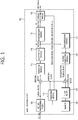
- FIG. 1 is a block diagram schematically illustrating an image encoding device (encoder) according to an embodiment of the invention.
- an image encoding device 100 includes a picture partitioning module 105, a prediction module 110, a transform module 115, a quantization module 120, a rearrangement module 125, an entropy encoding module 130, a dequantization module 135, an inverse transform module 140, a filter module 145, and a memory 150.
- the picture partitioning module 105 may partition an input picture into at least one process unit.
- the process unit may be a prediction unit (hereinafter, referred to as a "PU"), a transform unit (hereinafter, referred to as a "TU”), or a coding unit (hereinafter, referred to as a "CU").
- a prediction unit may be expressed by a prediction block
- a transform unit may be expressed by a transform block
- a coding unit may be expressed by a coding block.
- the prediction module 110 includes an inter prediction module that performs an inter prediction process and an intra prediction module that performs an intra prediction process, as described later.
- the prediction module 110 performs a prediction process on the process units of a picture divided by the picture partitioning module 105 to create a prediction block.
- the process unit of a picture may be a CU, a TU, or a PU. It may be determined whether the prediction performed on the corresponding process unit is an inter prediction or an intra prediction, and specific details (for example, a prediction mode) of the prediction methods may be determined.
- the process unit subjected to the prediction process may be different from the process unit of which the prediction method and the specific details are determined. For example, the prediction method and the prediction mode may be determined by the PU units and the prediction process may be performed by the TU units.
- a prediction process is performed on the basis of information on at least one of a previous picture and/or a subsequent picture of a current picture to create a prediction block.
- a prediction process is performed on the basis of pixel information of a current picture to create a prediction block.
- a reference picture is selected for a PU, and a reference block having the same size as the PU may be selected by integer pixel samples. Then, a prediction block in which a residual signal with the current PU is minimized and the motion vector magnitude is minimized is created.
- a skip mode, a merge mode, an MVP (Motion Vector Prediction), or the like may be used as the intra prediction method.
- the prediction block may be created in the unit of pixel samples less than an integer pixel such as 1/2 pixel samples and 1/4 pixel samples.
- the motion vector may also be expressed in the unit of pixel samples less than an integer pixel. For example, luma pixels may be expressed in the unit of 1/4 pixels and chroma pixels may be expressed in the unit of 1/8 pixels.
- Information such as an index, a motion vector (for example, a motion vector predictor), and a residual signal of a reference picture selected through the inter prediction is entropy-encoded and is transmitted to a decoder.
- the prediction mode may be determined in the unit of PU and the prediction process may be performed in the unit of PU.
- the prediction mode may be determined in the unit of PU and the inter prediction may be performed in the unit of TU.
- the prediction modes in the intra prediction include 33 directional prediction modes and at least two non-directional modes.
- the non-directional modes include a DC prediction mode and a planar mode.
- a prediction block may be produced after a filter is applied to a reference sample. At this time, it may be determined whether a filter should be applied to a reference sample depending on the intra prediction mode and/or the size of a current block.
- the current block may be a transform unit to be subjected to a prediction process.
- use of a pixel in this specification means that information the pixel such as a pixel value is used. For the purpose of convenience for explanation, it should be noted that an expression "information of a pixel is used" or "a pixel value is used” may be simply expressed by "a pixel is used”. The specific intra prediction method is as described later.
- a PU has various sizes and shapes.
- a PU may have sizes such as 2Nx2N, 2NxN, Nx2N, and NxN.
- a PU may have sizes such as 2Nx2N and NxN (where N is an integer).
- the PU with a size of NxN may be set to be applied to only a specific case.
- the PU with a size of NxN may be set to be used for only a smallest coding unit or may be set to be used for only intra prediction.
- Pus having sizes such as NxmN, mNxN, 2NxmN, and mNx2N (where m ⁇ 1) may be additionally defined and used.
- Residual values (a residual block or a residual signal) between the produced prediction block and the original block are input to the transform module 115.
- the prediction mode information, the motion vector information, and the like used for the prediction are encoded along with the residual values by the entropy encoding module 130 and are transmitted to the decoder.
- the transform module 115 performs a transform process on the residual block in the unit of TU and outputs transform coefficients.
- the transform unit in the transform module 115 may be a TU and may have a quad tree structure.
- the size of the transform unit may be determined within a predetermined largest and smallest size range.
- the transform module 115 may transform the residual block using DCT (Discrete Cosine Transform) and/or DST (Discrete Sine Transform).
- DCT Discrete Cosine Transform
- DST Discrete Sine Transform
- the quantization module 120 may quantize the residual values transformed by the transform module 115 and may output quantization coefficients.
- the values calculated by the quantization module 120 may be supplied to the dequantization module 135 and the rearrangement module 125.
- the rearrangement module 125 may rearrange the quantization coefficients supplied from the quantization module 120. By rearranging the quantization coefficients, it is possible to enhance the encoding efficiency in the entropy encoding module 130.
- the rearrangement module 125 may rearrange the quantization coefficients in the form of a two-dimensional block to the form of a one-dimensional vector through the use of a coefficient scanning method.
- the rearrangement module 125 may enhance the entropy encoding efficiency in the entropy encoding module 130 by changing the order of coefficient scanning on the basis of stochastic statistics of the coefficients transmitted from the quantization module.
- the entropy encoding module 130 performs an entropy encoding process on the quantization coefficients rearranged by the rearrangement module 125.
- Examples of the entropy encoding method include an exponential golomb method, a CAVLC (Context-Adaptive Variable Length Coding) method, and a CABAC (Context-Adaptive Binary Arithmetic Coding) method.
- the entropy encoding module 130 may encode a variety of information such as residual coefficient information and block type information of a coding unit, prediction mode information, dividing unit information, prediction unit information, transfer unit information, motion vector information, reference picture information, block interpolation information, and filtering information transmitted from the rearrangement module 125 and the prediction module 110.
- the entropy encoding module 130 may give a predetermined change to a parameter set or syntax to be transmitted, if necessary.
- the dequantization module 135 dequantizes the values quantized by the quantization module 120.
- the inverse transform module 140 inversely transforms the values dequantized by the dequantization module 135.
- the residual values genrateed by the dequantization module 135 and the inverse transform module 140 are merged with the prediction block predicted by the prediction module 110 to create a reconstructed block.
- the filter module 145 applies a deblocking filter, an ALF (Adaptive Loop Filter), an SAO (Sample Adaptive Offset) to the reconstructed picture.
- ALF Adaptive Loop Filter
- SAO Sample Adaptive Offset
- the deblocking filter removes a block distortion generated at the boundary between blocks in the reconstructed picture.
- the ALF performs a filtering process on the basis of the result values of the comparison of the original picture with the reconstructed picture of which the blocks are filtered by the deblocking filter.
- the ALF may be applied only when high efficiency is necessary.
- the SAO reconstructs offset differences between the residual blocks having the deblocking filter applied thereto and the original picture and is applied in the form of a band offset, an edge offset, or the like.
- the filter module 145 may not perform a filtering process on a reconstructed block used for the inter prediction.
- the memory 150 stores the reconstructed block or picture calculated by the filter module 145.
- the reconstructed block or picture stored in the memory 150 is supplied to the prediction module 110 when performing the inter prediction.
- FIG. 2 is a block diagram schematically illustrating an image decoding device according to an embodiment of the invention.
- an image decoding device 200 includes an entropy decoding module 210, a rearrangement module 215, a dequantization module 220, an inverse transform module 225, a prediction module 230, a filter module 235, and a memory 240.
- the input bitstream is decoded on the basis of the order in which image information is processed by the image encoding device.
- the image decoding module 210 may realize the same VLC table as used in the image encoding device and may perform the entropy decoding process.
- the image encoding device uses the CABAC to perform the entropy encoding process
- the entropy decoding module 210 may perform the entropy decoding process using the CABAC to correspond thereto.
- Information for creating a prediction block out of the information decoded by the entropy decoding module 210 is supplied to the prediction module 230, and the residual values entropy-decoded by the entropy decoding module are input to the rearrangement module 215.
- the rearrangement module 215 rearranges the bitstream entropy-decoded by the entropy decoding module 210 on the basis of the rearrangement method in the image encoding device.
- the rearrangement module 215 reconstructs and rearranges coefficients expressed in the form of one-dimensional vector into coefficients of a two-dimensional block form.
- the rearrangement module 215 is supplied with information associated with the coefficient scanning performed by the encoding module and may perform the rearrangement using a method of inversely scanning the coefficients on the basis of the scanning order in which the scanning is performed by the corresponding encoding module.
- the dequantization module 220 performs dequantization on the basis of the quantization parameters supplied from the encoder and the rearranged coefficient values of the block.
- the inverse transform module 225 performs the inverse DCT and inverse DST of the DCT and DST, which has been performed by the transform module of the image encoding device, on the quantization result from the image encoding device.
- the inverse transform is performed on the basis of a transfer unit or a division unit of a picture determined by the image encoding device.
- the transform module of the image encoding device selectively performs the DCT and DST depending on plural information elements such as the prediction method, the size of the current block, and the prediction direction, and the inverse transform module 225 of the image decoding device performs the inverse transform on the basis of the transform information on the transform performed by the transform module of the image encoding device.
- the prediction module 230 creates a prediction block on the basis of prediction block creation information supplied from the entropy decoding module 210 and the previously-decoded block and/or picture information supplied from the memory 240.
- the reconstructed block may be derived using the prediction block generated by the prediction module 230 and the residual block supplied from the inverse transform module 225.
- the prediction mode of a current PU is an intra prediction mode (intra mode)
- an intra prediction process of creating a prediction block on the basis of pixel information in the current picture may be performed.
- an inter prediction process may be performed on the current PU on the basis of information included in at least one of a previous picture or a subsequent picture of the current picture.
- motion information necessary for the inter prediction of the current PU supplied from the image encoding device for example, information on motion vectors, reference picture indices, and the like, may be derived from a skip flag, a merge flag, and the like received from the encoder.
- the reconstructed block and/or picture are supplied to the filter module 235.
- the filter module 235 performs a deblocking filtering process, an SAO (Sample Adaptive Offset) process, and/or an adaptive loop filtering process on the reconstructed block and/or picture.
- SAO Sample Adaptive Offset
- the memory 240 stores the reconstructed picture or block for use as a reference picture or a reference block and supplies the reconstructed picture to the output module.
- the decoder and the encoder derive the motion information of a current block and perform the inter prediction on the current block on the basis of the derived motion information.
- FIG. 3 is a flowchart schematically illustrating an example of a method of deriving a motion vector when an AMVP (Advanced Motion Vector Predictor) is applied to the inter prediction mode.
- AMVP Advanced Motion Vector Predictor
- the encoder and the decoder may derive a motion vector predictor (hereinafter, referred to as "MVP") candidate list of a current block (S310).
- the MVP represents a predicted value of a motion vector of the current block.
- the encoder and the decoder may generate an MVP candidate list using motion vectors of available neighbouring blocks adjacent to the current block and/or available blocks (hereinafter, referred to as "Col block” (co-located block) for the purpose of convenience for explanation) out of blocks of reference pictures co-located with the current block.
- Col block co-located block
- a block adjacent to a current block is defined as a "neighbouring block" for the purpose of convenience for explanation.
- the encoder and the decoder may select the MVP of the current block out of the MVP candidates included in the MVP candidate list.
- the encoder may select the optimal MVP of the current block by applying motion vector competition (MVC) on the MVP candidates included in the MVP candidate list.
- MVC motion vector competition
- the encoder transfers an MVP index to the decoder using a bitstream.
- the MVP index is an index indicating the MVP of the current block and is selected from the MVP candidates included in the MVP candidate list.
- the decoder receives the MVP index from the encoder.
- the decoder selects the MVP of the current block out of the MVP candidates included in the MVP candidate list using the received MVP index.
- the decoder may derive a motion vector of the current block using the selected MVP (S330).
- the encoder calculates a difference between the motion vector of the current block and the MVP.
- the difference between the motion vector and the MVP is referred to as a motion vector difference (hereinafter, referred to as "MVD").
- the encoder may transfer information on the MVD instead of the motion vector to the decoder.
- the amount of information transferred from the encoder to the decoder may become smaller.
- the decoder receives the information on the MVD from the encoder.
- the decoder adds the MVD to the selected MVP to calculate the motion vector of the current block.
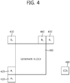
- FIG. 4 is a conceptual diagram schematically illustrating an example of a method of creating an MVP candidate list.
- a candidate group including a left-bottom neighbouring block A 0 410 which is a neighbouring block at the left-bottom corner of a current block 400 and a left block A 1 420 which is located at the bottom out of the left neighbouring blocks of the current block 400 is defined as a left candidate group.
- a candidate group including a top-right neighbouring block B 0 430 which is a neighbouring block at the top-right corner of the current block 400, a right neighbouring block B 1 440 which is located on the rightmost side out of the top neighbouring blocks of the current block 400, and a top-left block B 2 450 which is a neighbouring block at the top-left corner of the current block 400 is defined as a top candidate group.
- the encoder and the decoder selects one MVP candidate from the left candidate group (A 0 and A 1 ).
- the MVP candidate selected from the left candidate group is defined as MV A .
- the encoder and the decoder may select the motion vector of the first block, which has the same reference picture index as the current block and which is available, as the MVP candidate MV A of the current block while scanning the blocks included in the left candidate block in the order of A 0 ⁇ A 1 .
- the encoder and the decoder also may select one MVP candidate from the top candidate group (B 0 , B 1 , and B 2 ).
- the MVP candidate selected from the top candidate group is defined as MV B .
- the encoder and the decoder select the motion vector of the first block, which has the same reference picture index as the current block and which is available, as the MVP candidate MV B of the current block while scanning the blocks included in the top candidate group in the order of B 0 ⁇ B 1 ⁇ B 2 .
- the encoder and the decoder may select the motion vector of a Col block COL 460 in a reference picture as the MVP candidate of the current block.
- the motion vector of the Col block 660 is expressed by mvCol.
- the MVP candidate selected from the left candidate group and the MVP candidate selected from the top candidate are referred to as spatial motion vector predictor (hereinafter, referred to as "SMVP").
- the MVP candidate selected using the Col block in the reference picture is referred to as a temporal motion vector predictor (hereinafter, referred to as "TMVP"). Therefore, the MVP candidate list includes the SMVP and/or the TMVP.
- the encoder and the decoder may remove the other candidates other than the highest-ranked candidate out of the overlapping candidates.
- the TMVP as well as the SMVP is used for the inter prediction of the current block.
- FIG. 5 is a flowchart schematically illustrating an example of a method of deriving a TMVP for an inter prediction in a decoder.
- the operations of the decoder is illustrated in FIG. 5 for the purpose of convenience for explanation, but an encoder also performs the same operations as the decoder to perform an inter prediction using the same TMVP candidate as in the decoder. Therefore, the operations of the decoder described with reference to FIG. 5 may be similarly applied to the decoder.
- the decoder first specifies a co-located picture (hereinafter, referred to as "colPic") including a col block (co-located block) or a col partition (co-located partition) (S510).
- colPic co-located picture
- S510 col partition
- the decoder may specify the colPic on the basis of information on a slice type and information on from what reference picture list the colPic is selected.
- the colPic is specified from L1.
- Pictures used for encoding and decoding an image may be classified into an I picture, a P picture, and a B picture.
- the I picture is a picture which is independently encoded using its own picture regardless of the previous and subsequent pictures thereof. Temporal prediction is not applied to the I picture and only intra information is used for the encoding thereof.
- the P picture is a picture which may be encoded by unidirectional inter prediction using a single reference picture.
- the P picture requires one reference picture list, which is called reference picture list 0 (L0).
- the inter prediction using a reference picture selected from L0 is also called L0 prediction.
- the L0 prediction is used mainly for forward prediction.
- the intra prediction or the L0 prediction may be performed for the P picture.
- the B picture is a picture which may be encoded through forward, backward, or bidirectional inter prediction using two reference pictures.
- the B picture requires two reference picture lists, which are called reference picture list 0 (L0) and reference picture list 1 (L1).
- L0 prediction the inter prediction using a reference picture selected from L0 is called L0 prediction.
- L0 prediction is used mainly for forward prediction.
- L1 prediction the inter prediction using a reference picture selected from L1
- the L1 prediction is used mainly for backward prediction.
- the inter prediction using two reference pictures selected from L0 and L1 is called bi prediction.
- the intra prediction, the L0 prediction, the L1 prediction, or the bi prediction may be performed for the B picture.
- Two pieces of motion information may be used for the B picture. Therefore, the forward prediction may be performed for the B picture using two previous reference pictures, the backward prediction may be performed using two subsequent reference pictures, and the bi prediction may be performed using one previous reference picture and one subsequent reference picture.
- the B picture on which the bi prediction may be performed requires two reference picture lists of L0 and L1.
- the features of the I picture, the P picture, and the B picture may be defined in the unit of slices, not in the unit of pictures.
- an I slice having the feature of the I picture in the unit of slices, a P slice having the feature of the P picture, and a B slice having the feature of the B picture may be defined.
- the colPic may be selected from L0.
- the decoder may specify a co-located prediction block colPu to be used for prediction of a current block from the selected colPic (S520).
- the decoder may use information of the colPu specified in the colPic as the TMVP in inter prediction of a current block.
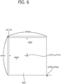
- FIG. 6 is a diagram schematically illustrating a method of specifying a colpu.
- the position of a pixel sample S TL located at the top-left corner of a col block 600, corresponding to a current block, in a colPic is specified as (xP, yP).
- the current block and the col block may be a PU.
- the width of the current block is defined as nPSW and the height of the current block is defined as nPSH
- the position of a pixel sample S RB located at the right-bottom corner of the col block 600 is specified as (xPRb, yPRb). Therefore, the size of the current block (col block) is specified by S RB .
- S RB serves as a positioning pixel as described later.
- a prediction block covering the top-left corner of a predetermined motion data storage unit to which S RB belongs in the colPic is specified as a colPu (co-located prediction unit).
- S RB serves as a pixel for positioning the position of the colPu.
- the motion data storage unit is a unit for storing motion information used for prediction in the inter prediction.
- a block with a predetermined size may be set as a motion data storage unit and one piece of motion information may be stored for each motion data storage unit. For example, when one value is designated and stored for every NxN samples (where N is an integer) in a colPic and motion information of a specific block in the colPic is used for the inter prediction, motion information of the motion data storage unit covering the specific block may be used.
- the motion data storage unit may be set as a sample block having a specific size such as 4x4 samples, 6x6 samples, 8x8 samples, 12x12 samples, 16x16 samples, 32x32 samples, and 64x64 samples.
- the motion information may be stored in the unit of sample block having the set size.
- the position of ((xPRb>>4) ⁇ 4, (yPRb>>4) ⁇ 4) may be specified as the position of the colPu covering the top-left corner of the motion data storage unit to which S RB belongs.
- the colPu may be specified on the basis of a sample S CTR located at the center (specifically, at the center right-bottom corner specified by 1/2 of the col block size) of the col block. Therefore, S CTR also serves as a positioning pixel for positioning the colPu.
- the position (xPCtr, yPCtr) of the S CTR may be specified as (xP+(nPSW>>1), yP+(nPSH>>1)).
- the prediction block covering the top left corner of the motion data storage unit to which S CTR belongs may be specified as the colPu.
- the position ((xPCtr>>4) ⁇ 4, (yCtr>>4) ⁇ 4) may be specified as the position of the colPu.
- the position (xPCol, yPCol) of the colPu in the colPic may be specified as the position of the top-left sample of the colPu with respect to the position of the top-left sample of the colPic.
- the decoder may derive information on a temporal motion vector and availability of a reference list to be used for prediction of a current block on the basis of information of the colPu (S530).
- the temporal motion vector mvCol may be set to 0 and the reference list may be set to be unavailable.
- availableFlagLXCol (where X is 0 or 1) may be used as information indicating the availability of the reference list. It is determined that the reference picture list is available when the value of availableFlagLXCol is 0, and it is determined that the reference picture list is unavailable when the value of availableFlagLXCol is 1.
- TMVP Temporal Motion Vector Predictor
- the value of the temporal motion vector mvCol and the value of reference index refIdxCol may be specified using L1 as a reference list and using data of the colPu.
- the value of temporal motion vector mvCol may be set to MvL1[xPCol][yPCol] and the value of reference index refIdxCol may be set to refIdxL1[0xPCol][yPCol].
- the value of the temporal motion vector mvCol and the value of the reference index refIdxCol may be specified using L0 as a reference list and using data of the colPu.
- the value of temporal motion vector mvCol may be set to MvL0[xPCol][yPCol] and the value of reference index refIdxCol may be set to refIdxL0[xPCol][yPCol].
- temporal motion information may be determined by comparing a picture order count of a current picture with a picture order count of pictures in each reference picture list. For example, when the picture order count of the current picture is equal to or larger than the picture order count of the pictures in the reference picture lists, the motion vector and the reference index indicated by the position (xPCol, yPCol) of the colPu in the reference picture list used to derive the temporal motion information may be set as the values of mvCol and refldxCol, respectively.
- the motion vector and the reference index indicated by the position (xPCol, yPCol) of the colPu in the corresponding reference picture list may be set as the values of mvCol and refldxCol, respectively, using the reference picture list indicated by signaling from the encoder.
- the decoder may use the TMVP, which has the temporal motion vector and the reference picture index derived as motion information, as an MVP candidate.
- TMVP which has the temporal motion vector and the reference picture index derived as motion information
- the derived mvCol itself may be used as a temporal motion vector.
- the derived mvCol may be scaled and used as a temporal motion vector.
- the motion information of the colPu used in the TMVP may be stored by a predetermined motion data storage unit. That is, the colPu may be set by a motion data storage unit and the motion information of the colPu may be used as the motion information of blocks belonging to the corresponding motion data storage unit.
- N 1 XN 2 (where N 1 and N 2 are integers) block serving as a motion data storage unit may be set in advance or may be signaled from the encoder.
- FIG. 7 is a diagram schematically illustrating a method of storing motion information.
- FIG. 7 shows an example where blocks B0 to B15 which are minimum units for setting motion information are set as a single motion data storage unit.
- the motion data block may be a CU, a PU, a TU, or a unit other than the CU, the TU, and the PU.
- the motion data block may correspond to a block specified by S TL , S RB , and S CTR described with reference to FIG. 6 .
- the motion data storage unit 700 is a block of 16x16 samples.
- Whether to compress and store motion information by storage units and what storage unit to use may be set in advance or may be signaled from the encoder.
- a flag representing whether to compress and store motion information by storage units and compression ratio information (motion_vector_buffer_comp_ratio) on how many motion data blocks (or how many pixels) to set as a single storage unit may be used.
- motion_vector_buffer_comp_flag when the value of motion_vector_buffer_comp_flag is 1, motion information may be compressed and stored by the storage units.
- motion_vector_buffer_comp_ratio 4x4 motion data blocks may be used as a single motion data storage unit as shown in FIG. 7 .
- the decoder may first apply an adaptive loop filter thereto and then may use the motion vector (X0, Y0) of the left-uppermost motion data block B0 in the motion data storage unit shown in FIG. 7 may be used as the representative value of the motion data storage unit 700. That is, the motion vector value of (X0, Y0) is assigned to the other 15 motion data blocks B1 to B15.
- a motion data block having the motion vector stored as the representative motion vector of the motion data storage unit is referred to as a representative motion data block.
- the representative motion data block may correspond to the colPu described with reference to FIG. 5 .
- the block B0 which is the representative motion data block is a block not available for the inter prediction, for example, a block encoded in an intra prediction mode (hereinafter, referred to as "intra block” for the purpose of convenience for explanation), a zero motion vector (0, 0) is assigned to the 16 motion data blocks.
- intra block a block encoded in an intra prediction mode
- the motion vector (X0, Y0) of the motion data block B0 is stored as the representative motion vector of the 16 motion data blocks B0 to B15 in a motion vector buffer for deriving the temporal motion vector (TMVP).
- the motion vector (0, 0) is stored as the representative motion vector of the motion data storage unit 700 in the motion vector buffer for deriving the TMVP.
- the motion information of the left-uppermost block B0 is assigned to the motion data blocks in the motion data storage unit.
- a distortion may be caused by assigning the same motion vector without considering the reference indices of the motion data blocks in the motion data storage unit.
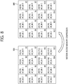
- FIG. 8 is a diagram schematically illustrating an example where motion vector memory compression (motion vector storage reduction) is performed without considering the reference indices.
- the motion vector storage reduction means that a single motion vector (representative motion vector) or a single piece of motion information (representative motion information) is assigned to the motion data blocks in the motion data storage unit and the result is stored and used, as described above.
- NxN (where N is an integer) motion data blocks are used as a single motion data storage unit
- a motion vector of a motion data block located at another specific position instead of the motion vector of the motion data block located at the left-top corner in the motion data storage unit is stored and used as the representative motion vector of the motion data storage unit.
- the motion vector to be used as the representative motion vector may be any one of (1) the motion vector of a motion data block located at the right-top (RT) corner, (2) the motion vector of a motion data block located at the bottom-left (BL) corner, (3) the motion vector of a motion data block located at the bottom-right (BR) corner, (4) the motion vector of the left-top (Center_LT) motion data block of the motion data blocks located at the center, (5) the motion vector of the right-top (Center_RT) motion data block of the motion data blocks located at the center, (6) the motion vector of the bottom-left (Center_BL) motion data block of the motion data blocks located at the center, and (7) the motion vector of the bottom-right (Center_BR) motion data block of the motion data blocks located at the center in the motion data storage unit.
- RT right-top
- BL bottom-left
- BR bottom-right
- the decoder may assign the motion vector of the motion data block specified out of (1) to (7) instead of the motion vector of the motion data block located at the top-left corner in the motion data storage unit to the motion data blocks and may use the assigned motion vector to derive the TMVP.
- FIG. 9 is a diagram schematically illustrating motion information of motion data blocks when 4x4 motion data blocks are set as a single motion data storage unit in a system to which the invention is applied.
- a motion data block other than the motion data block B0 may be designated as the representative motion data block and the motion vector of the designated representative motion data block may be used as the motion vector of the motion data storage unit 900.
- motion data block to designate as the representative motion data block may be determined in advance or may be signaled from the encoder.
- the motion vector of the motion data storage unit 900 is (X3, Y3).
- the motion vector of the motion data storage unit 900 is (X12, Y12).
- the motion vector of the motion data storage unit 900 is (X15, Y15).
- the motion vector of the motion data storage unit 900 is (X5, Y5).
- the motion vector of the motion data storage unit 900 is (X6, Y6).
- the motion vector of the motion data storage unit 900 is (X9, Y9).
- the motion vector of the motion data storage unit 900 is (X10, Y10).
- the position of the motion data block having motion information used as the representative value in motion information compression and storage may be adaptively determined depending on the unit to be compressed, that is, the size of the motion data storage unit. For example, when the unit to be compressed is determined and transferred by the encoder, the position of the block (motion data block) having the motion vector (motion information) used for compression may be determined depending on the value of motion_vector_buffer_comp_ratio.
- the motion vector of the motion data block located at the bottom-right corner may be used as the motion vector of the corresponding motion data storage unit (the motion data block located at the bottom-right corner may be used as the representative motion data block).
- the value of motion_vector_buffer_comp_ratio is 8 or 16
- the motion vector of the motion data block located at the central bottom-right (Center_BR) corner may be used as the motion vector of the corresponding motion data storage unit (the motion data block located at the central bottom-right corner may be used as the representative motion data block).
- the position of the representative motion data block which is determined depending on the units to be compressed, that is, various sizes of the motion data storage unit is not limited to the above-mentioned position.
- This embodiment provides a method of preventing a zero motion vector from being stored as the representative motion vector because the representative motion data block from which the representative motion vector value is designated is an intra block.
- a block is an intra block or an inter block by scanning the motion data blocks in the motion data storage unit in a predetermined order, and the motion vector of the first motion data block detected as the inter block is used as the representative motion vector of the motion data storage unit.
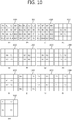
- FIG. 10 is a diagram schematically illustrating an order for searching for a prediction mode in which a motion data block in a motion data storage unit is coded according to the invention.
- FIG. 10 shows an example where a motion data storage unit 1000 includes 4x4 motion data blocks B0 to B15.
- I represents the scan order.
- the motion data block located at the top-left corner in the motion data storage unit 1000 is designated as the first block B0 for scanning the motion data blocks, and it is determined whether it is an inter block or an intra block (or whether it is available, that is, whether a motion vector is stored in L0 when a motion vector for L0 is stored) in the raster scan order.
- the motion data block located at the central bottom-right corner in the motion data storage unit 1000 is set as the first block B0 to be scanned and the scanning is performed in the spiral clockwise direction.
- the motion data block located at the central top-left corner in the motion data storage unit 1000 is set as the first block B0 to be scanned and the scanning is performed in the spiral clockwise direction.
- the scanning unit is set to double the scanning unit set in (a) to (c) of FIG. 10 and the scanning is performed.
- the scanning is performed in the unit of blocks of 8x8 samples in (k) to (m) of FIG. 10 . Therefore, the first motion data block located at the top-left corner in the block of 8x8 samples is scanned.
- the motion data storage unit 1000 includes 4x4 motion data blocks, the top-left motion data block in each of 2x2 motion data blocks scanned in the clockwise direction from the top-left 2x2 motion data blocks in the example shown in (k) of FIG. 10 .
- the scanning order is B0 ⁇ B1 ⁇ B2 ⁇ B3 as shown in the drawing.
- the top-left motion data block in each of 2x2 motion data blocks scanned in the counterclockwise direction from the bottom-left 2x2 motion data blocks For example, the scanning order is B0 ⁇ B1 ⁇ B2 ⁇ B3 as shown in the drawing.
- the top-left motion data block in each of 2x2 motion data blocks scanned in the zigzag direction from the bottom-left 2x2 motion data blocks For example, the scanning order is B0 ⁇ B1 ⁇ B2 ⁇ B3 as shown in the drawing.
- the decoder uses the motion vector of the motion data block first detected to be encoded in an inter prediction mode as the representative motion vector of the corresponding motion data storage unit 1000.
- representative motion information of a motion data storage unit may be stored on the basis of the information of an intra block.
- the motion data block located at a position to be referred to in Embodiment 1 is an intra block (or when the motion vector of a target reference list is not available) and when all the motion data blocks of the motion data storage unit are intra blocks (or when the motion vector of a target reference list is not available)
- the zero motion vector (0, 0) is used as the representative motion vector of the motion data storage unit.
- This embodiment provides a method of storing motion information with reference to neighbouring blocks of a motion data storage unit of a current block (hereinafter, referred to as a "current motion data storage unit").
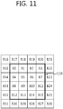
- FIG. 11 is a diagram schematically illustrating a method of storing motion information of a current motion data storage unit using neighbouring blocks of the current motion data storage unit according to the invention.
- FIG. 11 shows an example where a motion data storage unit includes 4x4 motion data blocks.
- motion information of the current motion data storage unit 1100 is stored and used using the motion information of the neighbouring blocks B16 to B35 of the current motion data storage unit 1100.
- the neighbouring blocks B16 to B35 may be motion data blocks.
- the motion information of the block is stored and used as the motion information of the current motion data storage unit 1100 including the intra blocks.
- the motion information of the block may be stored and used as the motion information of the current motion data storage unit 1100 including the intra blocks.
- the representative motion vector of the current motion data storage unit may be determined using any one method of (1) to (3) described below.
- a difference between the bottom-right pixel of the block B16 and the top-left pixel of the block B0 is calculated. Differences between the eight bottom pixels of the block B17 and the neighboring intra block B0 (or blocks in which the motion vectors of a target reference list is not available) are calculated and the resultant value is divided by 8 to calculate the average pixel difference.
- the pixel differences between the neighbouring blocks and the intra blocks (or blocks in which the motion vectors of a target reference list is not available) in the current motion data storage unit are calculated, and the motion information of the neighbouring block having the smallest difference is used as the motion information of the current motion data storage unit.
- a priority order may be given thereto in advance. For example, when the neighbouring blocks are ranked as shown in FIG. 11 , the motion information of the neighbouring block having the lower rank may be used as the motion information of the current motion data storage unit.
- the motion vector of the current motion data storage unit may be set to a zero vector.
- This embodiment provides a method of designating and storing a representative value for reference indices as well as the motion vector of the motion data storage unit in motion information compression and storage (motion information storage reduction).
- Embodiments 1 to 3 the memory compression or the storage reduction of storing only one motion vector by the motion data storage units is described above, but a method of designating a representative reference index value of a motion data storage unit and storing the designated representative reference index value along with the motion vector value will be described in Embodiment 4.
- the memory buffer for storing the reference indices may be reduced in Embodiment 4.
- the reference index as well as the motion vector of the representative motion data block is assigned to the other motion data blocks in the motion data storage unit.
- the decoder may use representative motion information (the motion information of the representative motion data block) as the motion information of the blocks in the motion data storage unit. Therefore, it is possible to solve the problem with a distortion because the motion vector value of the representative motion data block is assigned to the motion vectors of the motion data blocks of the motion data storage unit, but the reference indices are maintained.
- FIG. 12 is a diagram schematically illustrating a state in which motion information memory compression (motion information storage reduction) is performed on reference indices as well as motion vectors when performing motion vector memory compression (motion vector storage reduction).
- the motion information storage reduction means that only one piece of motion information (representative motion information) is assigned to the motion data blocks of a motion data storage unit and is stored and used as described above, similarly to the motion vector storage reduction.
- FIG. 12 shows an example where a motion data storage unit includes 4x4 motion data blocks.
- FIG. 12 shows an example where the motion information (the motion vector and the reference index) of the motion data block B0 located at the top-left corner of the motion data storage unit 1200 is used as representative motion information.
- the motion vector and the reference index of the motion data block B0 are assigned as motion information of a motion data storage unit 1210 by the motion information storage reduction.
- the motion vector and the reference index of the block B0 which is the representative motion data block are (X0, Y0) and ref_idx2, respectively.
- the motion vector (X0, Y0) and the reference index ref_idx2 of the block B0 may be used to derive the TMVP.
- the use of the reference index of the colPu along with the motion vector of the colPu corresponds to the storage and use of the reference index of the representative motion data block along with the motion vector thereof as the motion information of the motion data storage unit.
- the method according to Embodiment 4 may be applied along with the methods according to Embodiments 1 to 3.
- the motion vector and the reference index of the corresponding motion data block may be together assigned to the motion data storage unit.
- the reference index and the motion vector of the determined neighbouring block may be assigned to the current motion data storage unit.
- the reference index of the representative motion data block may be assigned to only the other motion data blocks without changing the reference index of the intra block.
- the reference index values of the corresponding motion data block in L1 and L0 may be directly read and determined to find out the prediction direction of the col block (the L0 direction, the L1 direction, the bi-prediction, or the intra prediction).
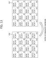
- FIG. 13 is a diagram schematically illustrating a state in which motion information memory compression of a motion vector and a reference index is performed on only an inter block according to the invention when performing motion vector memory compression.
- FIG. 13 shows an example where the motion data storage unit includes 4x4 motion data blocks.
- the blocks B10, B11, B14, and B15 out of the motion data blocks B0 to B15 in a motion data storage unit 1300 are intra blocks (of which the reference index has a value of -1).
- the reference indices of the inter blocks other than the intra block may be changed to the reference index of the representative motion data block and the motion vector and the reference index of the motion data storage unit 1310 may be set. Even when the motion vectors of the intra blocks B10, B11, B14, and B15 in the motion data storage unit 1310 are changed to the motion vector of the representative motion data block, the reference indices are not changed but maintained.
- the motion vector of the col block may be derived using the stored reference index values regardless of the picture type (the P picture, the B picture, and the I picture) of the col block, and the motion vector of the col block may be made not to be derived from the intra block.
- Embodiments 1 to 3 may be applied to Embodiments 1 to 3.
- the reference index of the intra block may not be changed.
- a neighbouring block of which the motion vector is used is determined out of the neighbouring blocks of the current motion data storage unit according to Embodiment 3 and the reference index of the determined neighbouring block is assigned to the current motion data storage unit, the reference index of the intra block may not be changed.
- difference reference indices may be assigned to the motion data blocks of the same motion data storage unit. In this case, only the motion vector is compressed and the reference indices are not compressed.
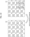
- FIG. 14 shows a method of storing only one representative value as the reference index as shown in FIG. 12 but inferring that a block is an intra block.
- FIG. 14 is a diagram schematically illustrating a method of inferring an intra block in a state in which motion information memory compression of a motion vector and a reference index is performed according to the invention when performing motion vector memory compression.
- FIG. 14 shows an example where the motion data storage unit includes 4x4 motion data blocks.
- the blocks B10, B11, B14, and B15 out of the motion data blocks B0 to B15 in a motion data storage unit 1300 are intra blocks (of which the reference index has a value of -1).
- the reference index value of the representative motion data block B0 is assigned to the blocks B10, B11, B14, and B15 which are intra blocks.
- the decoder may infer that the corresponding blocks are intra blocks. That is, the decoder may recognize that the motion information of the blocks B10, B11, B14, and B15 are not available.
- a motion data block is an intra block or an inter block by the use of the prediction type (an intra prediction mode or an inter prediction mode) of the CU to which the corresponding motion data block belongs.
- the method described with reference to FIG. 14 may be applied along with Embodiments 1 to 3.
- the motion vector and the reference index of the corresponding motion data block may be assigned to the motion data storage unit and it may be determined whether the corresponding motion data block is an intra block on the basis of the prediction type of the CU to which the corresponding block belongs.
- the reference index of the determined neighbouring block may also be assigned to the current motion data storage unit and it may be determined whether the determined neighbouring block is an intra block on the basis of the prediction type of the CU to which the corresponding block belongs.
- a motion vector may be made not to be derived from an intra block.
- This embodiment provides a method of combining Embodiment 2 and Embodiment 4 and considering whether a reference index is 0 as a motion information storage reduction method.
- the decoder may select a first-detected motion data block, which is encoded in an inter prediction mode and which has a reference index value of 0, as the representative motion data block while scanning the motion data blocks of the motion data storage unit in a predetermined order.
- the decoder may assign and use the motion vector and the reference index of the selected representative motion data block to the other motion data blocks of the motion data storage unit.
- This embodiment provides a method of compressing and storing a prediction mode along with the motion vector and the reference index in the motion information storage reduction (motion vector memory reduction).
- information on the prediction mode may be stored by the PU.
- the PU of which information on the prediction mode is stored may be a smallest prediction unit or a motion data block, and the smallest prediction unit or the motion data block may be a block of 4x4 samples.
- information on whether the prediction mode is an intra mode or an inter mode and on which one is used among a skip mode or a merge mode or an AMVP when the prediction mode is an inter mode may be stored.
- the information on the prediction mode may be stored in a decoded picture buffer (DPB) to check the state of the col block.
- DPB decoded picture buffer
- the information on the prediction mode may be stored by motion data storage units without storing the information on the prediction mode by PU units.
- the prediction mode of the representative motion data block of the motion data storage unit is also compressed (stored).
- FIG. 15 is a diagram schematically illustrating a state in which information on a prediction mode is compressed according to the invention when performing motion vector memory compression.
- FIG. 15 shows an example where a motion data storage unit includes 4x4 motion data blocks.
- 16 motion data blocks of a motion data storage unit 1500 are encoded in various prediction modes.
- the representative motion data block of the motion data storage unit 1500 is a motion data block B0 located at the top-left corner.
- the same motion vector, reference index, and prediction mode as the representative motion data block B0 are assigned to 4x4 motion data blocks in a motion data storage unit 1510 by the motion vector memory compression. Therefore, the motion vector of the motion data blocks B0 to B15 in the motion data storage unit 1510 is stored as (X0, Y0), the reference index thereof is stored as ref_idx 2, and the prediction mode thereof is stored as a skip mode.
- the motion data storage unit 1510 includes the block specified by S RB or S CRT in FIGS. 5 and 6 , (X0, Y0) which is the motion vector of B0, ref_idx 2 which is the reference index thereof, and a skip mode which is the prediction mode thereof may be used as motion information for deriving the TMVP of the current block.
- This embodiment provides a method of more effectively performing a compression process in the motion information storage reduction, for example, when compressing the motion vector buffer memory.
- the degradation in performance may be suppressed as the local motion information pieces are similar to each other, depending on the characteristics of a picture.
- the similarity of the local motion may vary depending on a picture and, for example, there may be a difference in compression performance between when a 16:9 picture is compressed by the motion data storage unit of 16x16 pixel blocks and when a 4:3 picture is compressed by the motion data storage unit of 16x16 pixel blocks.
- this embodiment provides a method of more dynamically compressing a buffer memory for storing motion information.
- the encoder may signal information on the compression ratio to the decoder, when information indicating compression of motion information or motion vectors at the sequence level is transferred. For example, when the motion information of NxM (where N and M are integers) sample blocks are compressed and stored as a single motion information piece, the encoder may signal the value of N relevant to the compression ratio in the horizontal direction and the value of M relevant to the compression ratio in the vertical direction.
- NxM where N and M are integers
- the encoder may transfer information such as motion_vector_buffer_comp_x_ratio_log2 as the information on the compression ratio in the horizontal direction in the motion information storage reduction and transfer information such as motion_vector_buffer_comp_y_ratio_log2 as the information on the compression ratio in the vertical direction.
- motion_vector_buffer_comp_x_ratio_log2 transferred by the encoder is 2 and the value of motion_vector_buffer_comp_y_ratio_log2 is 2, it may be indicated that compression of storing the motion information in the unit of 4x4 samples is performed.
- motion_vector_buffer_comp_x_ratio_log2 When the value of motion_vector_buffer_comp_x_ratio_log2 transferred by the encoder is 3 and the value of motion_vector_buffer_comp_y_ratio_log2 is 2, it may be indicated that compression of storing the motion information in the unit of 8x4 samples is performed.
- the compression storage ratio of motion information may be determined in consideration of the characteristics of a picture processed by the encoder and may be transferred to the decoder.
- the decoder may acquire information of the motion vector and/or the reference index for deriving the TMVP on the basis of the transferred compression storage ratio of motion information.
- Embodiment 7 since video data is compressed and stored in consideration of the characteristics of a picture, it is possible to maximally reduce loss in compression of a temporal motion vector buffer.
- the reference index buffer compression (memory compression) may be performed in the same way using the information on the motion vector buffer compression.
- Information for the reference index buffer compression may be signaled separately to perform the buffer compression separately from the motion vector buffer compression.
- the method of determining and signaling the size of a sample block which is a unit for storing motion information, that is, the compression and storage ratio, to the decoder may be similarly applied to Embodiments 1 to 6.
- the size of a sample block as the compression and storage unit determined by the encoder is NxM
- the motion data storage unit in Embodiments 1 to 6 is a block with a size of NxM samples.
- This embodiment provides a method of using a neighbouring block of a motion data storage unit instead of the motion data block in the motion data storage unit as the representative motion data block used to compress and store motion information.
- motion information may be compressed and stored using a 4x4 pixel block at the right-bottom corner adjacent to a current motion data storage unit as the representative motion data block having the motion information on the current motion data storage unit instead of using any motion data block in the current motion data storage unit which is a 16x16 pixel block as the representative motion data block.
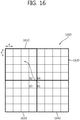
- FIG. 16 is a diagram schematically illustrating a method of utilizing information on blocks adjacent to a current motion data storage unit according to the invention when compressing and storing motion information.
- FIG. 16 shows an example where the motion data storage unit includes 4x4 motion data blocks.
- a PU 1600 includes four motion data storage units 1610, 1620, 1630, and 1640 and each motion data storage unit includes motion data blocks which are 4x4 pixel blocks.
- motion information (also referred to as "motion data") of a 4x4 pixel block B1 located adjacent to the right-bottom corner of the current motion data storage unit 1610 is used as the motion information of the current motion data storage unit 1610 to compress and store the motion information (such as the motion vector, the reference index, and the prediction mode) of the current motion data storage unit 1610 which is a 16x16 pixel block. That is, the block B1 is used as the representative motion data block of the current motion data storage unit 1610.
- the motion information of the block B1 is assigned to all the blocks in the current motion data storage unit 1610.
- the motion information of the neighbouring block adjacent to the right-bottom corner is assigned as the motion information of the respective motion data storage unit to the other motion data storage units 1620, 1630, and 1640 in the PU 1600 in the same way.
- the TMVP when the TMVP is taken out from a reference picture of which the motion information is compressed and stored in the process of prediction of a current block, a , and the motion information of the motion data blocks (blocks located on the central top-left side, the central left-bottom side, the central top-right, and the central right-bottom side) located at the center of the current PU may be simply used without performing an additional process of searching out neighbouring PU located at the right-bottom corner of a current PU every time and taking out the motion information of the top-left block of the motion data storage unit including the corresponding PU as described above.
- the motion data blocks located at the center of the current PU are B1, B2, B3, and B4 in the example shown in FIG. 16 .
- the other motion data blocks B2, B3, and B4 located at the center of the PU 1600 included the current motion data storage unit 1610 may be used as the representative motion data block of the current motion data storage unit 1610.
- the motion data blocks are scanned for the current motion data storage unit 1610 in any one order of (1) B1 ⁇ B2 ⁇ B3 ⁇ B4, (2) B1 ⁇ B3 ⁇ B4 ⁇ B2, (3) B1 ⁇ B4 ⁇ B3 ⁇ B2, and an inter block or an available block first detected may be used as the representative motion data block of the current motion data storage unit 1610.
- the scanning order may be determined in advance or may be signaled from the encoder.
- the motion information of a block having a size smaller than the compression and storage unit of motion information may be compressed and stored.
- This embodiment provides a method of compressing and storing motion information of pixel block smaller than the compression and storage unit of motion information.
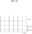
- FIG. 17 is a diagram schematically illustrating a method of compressing and storing motion information of a pixel block smaller than a compression and storage unit of motion information according to the invention when compressing and storing motion information.
- FIG. 17 shows an example where the size of a picture is not an integer multiple of the motion data storage unit and 16x16 pixel samples are used as a single motion data storage unit.
- a picture 1700 includes plural motion data storage units.
- a motion data storage unit is a 16x16 pixel block such as a block 1710 as described above.
- a block (hereinafter, referred to as a "remaining block" for the purpose of convenience for explanation) having a size smaller than the motion data storage unit is present at the boundary of the picture like a block 1720.
- the size of the remaining block is assumed to be 8x16.
- Embodiment 9 a method of storing motion information of the remaining block depending on what motion data block to use as the representative motion data block of the motion data storage unit will be described.
- the position of the motion data block which may be used as the representative motion data block is the same as described in Embodiment 1.
- FIG. 18 is a diagram schematically illustrating a method of compressing and storing motion information of a remaining block according to the invention when a representative motion data block is a top-left block of a motion data storage unit.
- a motion data storage unit 1810 in a picture 1800 is a 16x16 pixel block and a remaining block 1820 is a 16x8 pixel block.
- the method to be described with reference to FIG. 18 may be applied to motion data storage units and remaining blocks having sizes other than described above.
- the representative motion data block of the remaining block 1820 may be determined using the same method as the motion data storage unit 1810.
- the motion information of the motion data block 1840 located at the top-left corner of the remaining block 1820 is used as the motion information of the remaining block 1820.
- the representative motion data block of the remaining block may be determined using the same method as the motion data storage unit.
- FIG. 19 is a diagram schematically illustrating a method of compressing and storing motion information of a remaining block according to the invention when a representative motion data block is a right-bottom block of a motion data storage unit.
- a motion data storage unit 1910 in a picture 1900 is a 16x16 pixel block and a remaining block 1920 is a 16x8 pixel block.
- the method to be described with reference to FIG. 19 may be applied to motion data storage units and remaining blocks having sizes other than described above.
- a right-bottom motion data block 1930 is used as the representative motion data block of the motion data storage unit 1910
- the motion information of a motion data block 1940 located at the right-bottom corner of an available area of the remaining block 1920 is used as the motion information of the remaining block 1920.
- FIG. 20 is a diagram schematically illustrating a method of compressing and storing motion information of a remaining block when a representative motion data block is a right-bottom block of a motion data storage unit but an unavailable area is present in the remaining block.
- the motion information of a motion data block 2040 located at the top-left corner of the remaining block 2020 is used as the motion information of the remaining block 2020.
- the top-left area is always available, it is not necessary to perform a calculating operation for searching for a boundary of an available block.
- the positions of the central motion data blocks are expressed by Center_XX.
- XX represents any one of LT (Left-Top), RT (Right-Top), LB (Left-Bottom), and RB (Right-Bottom).
- What of LT, RT, LB, and RB to correspond to XX may be determined in advance or may be determined and signaled to the decoder by the encoder. For the purpose of convenience for explanation, it is assumed that XX is LT. The below description may be similarly applied to examples where XX is RT, RB, and LB.
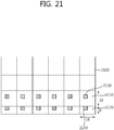
- FIG. 21 is a diagram schematically illustrating a method of compressing and storing motion information of a remaining block according to the invention when a representative motion data block is a central left-top (Center_LT) block of a motion data storage unit.
- Center_LT central left-top
- a motion data storage unit 2110 in a picture 2100 is a 16x16 pixel block and a remaining block 2120 is a 16x8 pixel block.
- the method to be described with reference to FIG. 21 may be applied to motion data storage units and remaining blocks having sizes other than described above.
- a central right top motion data block 2130 is used as the representative motion data block of the motion data storage unit 2110
- the motion information of a motion data block 2140 located on the central left-top side of an available area of the remaining block 2120 is used as the motion information of the remaining block 2120.
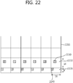
- FIG. 22 is a diagram schematically illustrating a method of compressing and storing motion information of a remaining block when a representative motion data block is a central left-top block of a motion data storage unit but an unavailable area is present in the remaining block.
- the motion information of a motion data block 2240 located at the top-left corner of the remaining block 2220 is used as the motion information of the remaining block 2220.
- the motion information of the motion data block 2240 located at the top-left corner of the remaining block 2220 may be used as the motion information of the remaining block 2220.
- the decoder and the encoder use the motion information of a motion data storage unit including a pixel located at a corner adjacent to the right-bottom of the col block of a current block as the TMVP motion information in the process of deriving the TMVP for the inter prediction as shown in FIG. 5 .
- the decoder and the encoder use the motion information of a representative motion data block out of the motion data blocks in the motion data storage unit as the motion information of the PUs in the motion data storage unit.
- the motion information of the representative motion data block of the motion data storage unit may include a reference index and a prediction mode in addition to a motion vector.
- motion vector prediction the motion information of a block adjacent to a current block is used as an MVP candidate and the co-located motion vector of an adjacent frame (picture) is also used as an MVP candidate, as described above.
- TMVP Temporal Motion Vector Predictor
- TMVP In order to use the TMVP, decoded information should be stored. Only when motion information such as a motion vector is stored in the unit of predetermined blocks (for example, 4x4 pixel block) after a frame (picture) is decoded, the TMVP may be used on the basis thereon in a next frame including a current block.
- motion information such as a motion vector is stored in the unit of predetermined blocks (for example, 4x4 pixel block) after a frame (picture) is decoded
- the TMVP may be used on the basis thereon in a next frame including a current block.
- motion information storage reduction motion vector memory compression
- motion vector buffer compression the unit of which the motion information is compressed and stored is described above as a motion data storage unit.
- unit to compress and store motion information may be determined in advance or may be determined and transferred to the decoder through SPS (Sequence Parameter Set)-level signaling by the encoder.
- the motion information (for example, the motion vector and the reference index) of a 4x4 block located at the top-left corner of the 16x16 pixel block is stored in the directions of L0 and L1.
- the motion information of a 4x4 pixel block located at the center of the 16x16 pixel block may be used instead of the motion information the block located at the left-top corner.
- FIG. 23 is a diagram schematically illustrating an example where motion information located at the center 2350 is used as a TMVP instead of motion data located at the left-top corner 2340 of a block 2330 located at the same position as a current block 2320 in a frame (or picture) 2310 adjacent to a current frame (or picture) 2300.
- TMV Temporal Motion Vector
- a TMV derived from an inter block may be set to have a value of (0, 0).
- FIG. 24 is a diagram schematically illustrating a method of processing motion information of an inter block located at the center when deriving a TMVP.
- a block which a current block 2410 should use to derive a TMVP is a central block 2440 in the co-located block 2430 of a neighboring frame 2420.
- the block 2440 is an intra block
- the value of the motion vector derived from the block 2440 is set to (0, 0) and thus inaccurate prediction may be performed.
- a neighboring block 2450 is an inter block and has a normal motion vector, it is not necessary to use the inaccurate motion vector of the block 2440.
- any one (for example, the central left-top block) of four blocks surrounding the center may be used depending on the size of the block, instead of the central block of the co-located block (col block).
- FIGS. 23 and 24 The details relevant to FIGS. 23 and 24 are described above, and embodiments for deriving a TMVP will be described below with reference to the accompanying drawings.
- This embodiment provides a method of using motion information of blocks located at the center of a col block when it is intended to derive a TMVP of a current block having various sizes.
- FIG. 25 is a diagram schematically illustrating a method of deriving a TMVP based on motion information of a block located at the center of a col block in a reference picture (reference frame) according to the invention.
- Fig. 25 shows an example where a storage unit (motion data storage unit) of motion information (for example, a motion vector) is a 16x16 pixel block for the purpose of convenience for explanation.
- the size of the motion data storage unit may be determined in advance or may be determined and transferred to the decoder through SPS-level signaling by the encoder.
- any one of (1) motion information of a motion data storage unit Bs0 located at the central left-top corner of the col block, (2) motion information of a motion data storage unit Bs1 located at the central right-top corner of the col block, (3) motion information of a motion data storage unit Bs2 located at the central left-bottom corner of the col block, and (4) motion information of a motion data storage unit Bs3 located at the central right-bottom corner of the col block is used to derive the TMVP from the col block 2510.
- What motion information of (1) to (4) to use may be determined in advance or may be determined and signaled to the decoder by the encoder.
- This embodiment provides a method of considering present of an intra block when deriving a TMVP of a current block.
- FIG. 26 is a diagram schematically illustrating a method of deriving a TMVP in consideration of presence or absence of an intra block according to the invention.
- FIG. 26 shows TMVP candidates of a reference frame located at the same position as a current block and being overlapped with the current block. Therefore, a block 2600, a block 2610, and a block 2620 may be considered as a current block or a col block of the current block.
- the blocks are col blocks of a current block.
- TMVP candidate groups are used for the purpose of convenience for explanation.
- Motion information of a block Bs0 adjacent to the right-bottom corner of a col block 2620 as a block located outside the col block 2620 of the current block and a motion data storage unit Bs1 located at the central right-bottom corner out of blocks located at the center of the col block 2620 may be used as TMVP candidates.
- the block Bs0 may be a motion data storage unit.
- the decoder first determines whether the block Bs0 outside the col block is an inter block (or an available block) or an intra block (or an unavailable block). When the block Bs0 is an inter block and is available, the decoder derives a TMVP using the motion information of the block Bs0. For example, the motion information of the block Bs0 may be used as the TMVP.
- the decoder determines whether the motion data storage unit Bs1 is an inter block (or an available block) or an intra block (or an unavailable block). When the block Bs1 is an inter block and is available, the decoder derives a TMVP using the motion information of the block Bs1.
- the decoder may derive a TMVP on the basis of the motion information of Bs0.
- the number, the positions, and the scan order of TMVP candidate groups in FIG. 26 are not limited to the above-mentioned details, and the size of the motion data storage unit is not limited to 16x16.
- the size of the current block and the col block is not limited 63x64, and the invention may be applied to various sizes such as 32x32. For example, when the size of a current block is 32x32 and the size of the motion data storage unit is 16x16, at most four TMVP candidates may be used for the current block.
- the TMVP may be derived using the motion information of the left-top corner of the col block or the like in the same way as described in the existing method.
- the above-mentioned embodiments relate to the motion information storage and compression method in an inter prediction and the method of deriving a TMVP using the stored motion information, and may be applied to an encoder and a decoder in the same way so as for the encoder and the decoder to perform the same prediction. Therefore, the embodiments are described as the operations of the decoder for the purpose of convenience for explanation, but may be similarly applied to the encoder.
- the invention includes embodiments in which the decoder in the above-mentioned embodiments is replaced with an "encoder".
- motion information storage reduction In the above description, “motion information storage reduction”, “motion vector memory compression”, “motion vector buffer compression”, “motion vector compression and storage”, “motion information compression and storage”, and the like are mixed depending on situations for the purpose of convenience for explanation, but they are intended for the purpose of convenience for explanation and may be used in the same meaning.
- the terms used for the purpose of convenience for explanation in the above description may be defined by the accompanying drawings and the relevant explanation thereof in addition to the used names.
Landscapes
- Engineering & Computer Science (AREA)
- Multimedia (AREA)
- Signal Processing (AREA)
- Compression Or Coding Systems Of Tv Signals (AREA)
Applications Claiming Priority (10)
| Application Number | Priority Date | Filing Date | Title |
|---|---|---|---|
| US201161440872P | 2011-02-09 | 2011-02-09 | |
| US201161443261P | 2011-02-16 | 2011-02-16 | |
| US201161445539P | 2011-02-23 | 2011-02-23 | |
| US201161448634P | 2011-03-02 | 2011-03-02 | |
| US201161451124P | 2011-03-10 | 2011-03-10 | |
| US201161473153P | 2011-04-08 | 2011-04-08 | |
| US201161478055P | 2011-04-21 | 2011-04-21 | |
| US201161478914P | 2011-04-25 | 2011-04-25 | |
| PCT/KR2012/000965 WO2012108701A2 (fr) | 2011-02-09 | 2012-02-09 | Procédé de stockage d'informations de mouvement et procédé destiné à induire un prédicteur de vecteur de mouvement temporel utilisant ce procédé |
| EP12745317.3A EP2675168A4 (fr) | 2011-02-09 | 2012-02-09 | Procédé de stockage d'informations de mouvement et procédé destiné à induire un prédicteur de vecteur de mouvement temporel utilisant ce procédé |
Related Parent Applications (1)
| Application Number | Title | Priority Date | Filing Date |
|---|---|---|---|
| EP12745317.3A Division EP2675168A4 (fr) | 2011-02-09 | 2012-02-09 | Procédé de stockage d'informations de mouvement et procédé destiné à induire un prédicteur de vecteur de mouvement temporel utilisant ce procédé |
Publications (5)
| Publication Number | Publication Date |
|---|---|
| EP3860124A2 true EP3860124A2 (fr) | 2021-08-04 |
| EP3860124A3 EP3860124A3 (fr) | 2021-09-01 |
| EP3860124C0 EP3860124C0 (fr) | 2025-04-02 |
| EP3860124B1 EP3860124B1 (fr) | 2025-04-02 |
| EP3860124B8 EP3860124B8 (fr) | 2025-05-07 |
Family
ID=46639067
Family Applications (2)
| Application Number | Title | Priority Date | Filing Date |
|---|---|---|---|
| EP21154242.8A Active EP3860124B8 (fr) | 2011-02-09 | 2012-02-09 | Procédé de stockage d'informations de mouvement et procédé destiné à induire un prédicteur de vecteur de mouvement temporel selon ce procédé |
| EP12745317.3A Withdrawn EP2675168A4 (fr) | 2011-02-09 | 2012-02-09 | Procédé de stockage d'informations de mouvement et procédé destiné à induire un prédicteur de vecteur de mouvement temporel utilisant ce procédé |
Family Applications After (1)
| Application Number | Title | Priority Date | Filing Date |
|---|---|---|---|
| EP12745317.3A Withdrawn EP2675168A4 (fr) | 2011-02-09 | 2012-02-09 | Procédé de stockage d'informations de mouvement et procédé destiné à induire un prédicteur de vecteur de mouvement temporel utilisant ce procédé |
Country Status (5)
| Country | Link |
|---|---|
| US (9) | US9148666B2 (fr) |
| EP (2) | EP3860124B8 (fr) |
| KR (8) | KR102109803B1 (fr) |
| CN (6) | CN103444182B (fr) |
| WO (1) | WO2012108701A2 (fr) |
Families Citing this family (61)
| Publication number | Priority date | Publication date | Assignee | Title |
|---|---|---|---|---|
| EP4124034B1 (fr) * | 2010-12-22 | 2023-08-23 | LG Electronics Inc. | Intraprédiction dans le codage vidéo |
| WO2012108701A2 (fr) * | 2011-02-09 | 2012-08-16 | 엘지전자 주식회사 | Procédé de stockage d'informations de mouvement et procédé destiné à induire un prédicteur de vecteur de mouvement temporel utilisant ce procédé |
| WO2012114712A1 (fr) * | 2011-02-25 | 2012-08-30 | パナソニック株式会社 | Procédé de codage d'images et procédé de décodage d'images |
| BR122020020892B1 (pt) | 2011-03-09 | 2023-01-24 | Kabushiki Kaisha Toshiba | Método para codificação e decodificação de imagem e a realização de interpredição em um bloco de pixels divididos |
| GB2488815C (en) * | 2011-03-09 | 2018-03-28 | Canon Kk | Video decoding |
| CN103392340B (zh) * | 2011-03-14 | 2017-02-08 | 寰发股份有限公司 | 推导运动向量预测子的方法与装置 |
| US9247266B2 (en) * | 2011-04-18 | 2016-01-26 | Texas Instruments Incorporated | Temporal motion data candidate derivation in video coding |
| MY170743A (en) * | 2011-06-30 | 2019-08-27 | Sony Corp | Image processing device and image processing method |
| US9521418B2 (en) | 2011-07-22 | 2016-12-13 | Qualcomm Incorporated | Slice header three-dimensional video extension for slice header prediction |
| US11496760B2 (en) | 2011-07-22 | 2022-11-08 | Qualcomm Incorporated | Slice header prediction for depth maps in three-dimensional video codecs |
| US9288505B2 (en) * | 2011-08-11 | 2016-03-15 | Qualcomm Incorporated | Three-dimensional video with asymmetric spatial resolution |
| US9485503B2 (en) * | 2011-11-18 | 2016-11-01 | Qualcomm Incorporated | Inside view motion prediction among texture and depth view components |
| US9900615B2 (en) * | 2011-12-28 | 2018-02-20 | Microsoft Technology Licensing, Llc | Representative motion information for temporal motion prediction in video encoding and decoding |
| EP2847996B1 (fr) | 2012-05-09 | 2020-10-07 | Sun Patent Trust | Procédé pour effectuer une prédiction de vecteur de mouvement, procédés de codage et de décodage, et appareils associés |
| KR101754999B1 (ko) * | 2012-08-29 | 2017-07-06 | 브이아이디 스케일, 인크. | 스케일러블 비디오 코딩을 위한 모션 벡터 예측 방법 및 장치 |
| CN104123716B (zh) * | 2013-04-28 | 2016-08-10 | 腾讯科技(深圳)有限公司 | 检测图像稳定性的方法、装置和终端 |
| KR102212631B1 (ko) * | 2013-05-24 | 2021-02-05 | 주식회사 케이티 | 멀티 레이어 구조에 있어서 움직임 정보의 유도 방법 및 이를 이용하는 장치 |
| WO2014189345A1 (fr) * | 2013-05-24 | 2014-11-27 | 주식회사 케이티 | Procede pour induire des informations de mouvement dans une structure multicouche et appareil l'utilisant |
| WO2015133320A1 (fr) * | 2014-03-05 | 2015-09-11 | ソニー株式会社 | Dispositif et procédé de codage d'image |
| WO2015139205A1 (fr) * | 2014-03-18 | 2015-09-24 | Mediatek Singapore Pte. Ltd. | Procédé amélioré pour image colocalisée en codage vidéo |
| CN105516724B (zh) * | 2014-09-23 | 2019-05-14 | 浙江大学 | 一种运动信息存储压缩方法 |
| WO2016049834A1 (fr) | 2014-09-30 | 2016-04-07 | Microsoft Technology Licensing, Llc | Décisions de codeur basées sur un algorithme de hachage pour un codage vidéo |
| US10382791B2 (en) * | 2015-03-06 | 2019-08-13 | Qualcomm Incorporated | Data structure for video coding unit |
| WO2016143972A1 (fr) * | 2015-03-11 | 2016-09-15 | 엘지전자(주) | Procédé et appareil pour le codage/décodage d'un signal vidéo |
| WO2016165069A1 (fr) * | 2015-04-14 | 2016-10-20 | Mediatek Singapore Pte. Ltd. | Prédiction de vecteurs mouvement temporelle avancée en codage vidéo |
| CN104811721B (zh) * | 2015-05-26 | 2017-09-22 | 珠海全志科技股份有限公司 | 视频解码数据存储方法及运动向量数据的计算方法 |
| US11178398B2 (en) | 2016-05-06 | 2021-11-16 | Samsung Electronics Co., Ltd. | Method and electronic device for coding a segment of an inter frame |
| CN112040244B (zh) | 2018-03-29 | 2021-06-29 | 华为技术有限公司 | 一种双向帧间预测方法及装置 |
| WO2019194513A1 (fr) * | 2018-04-01 | 2019-10-10 | 엘지전자 주식회사 | Procédé et dispositif de traitement de signal vidéo à l'aide de prédiction affine |
| WO2019194502A1 (fr) * | 2018-04-01 | 2019-10-10 | 엘지전자 주식회사 | Procédé de traitement d'image basé sur un mode d'inter-prédiction, et appareil associé |
| CN118200542A (zh) | 2018-04-01 | 2024-06-14 | Lg电子株式会社 | 图像编码/解码方法、数据的发送方法以及存储介质 |
| CN118175298A (zh) * | 2018-04-02 | 2024-06-11 | Lg电子株式会社 | 图片解码方法、图片编码方法和发送方法 |
| US10728542B2 (en) * | 2018-04-09 | 2020-07-28 | Tencent America LLC | Methods and apparatuses for sub-block motion vector prediction |
| CN110662070B (zh) | 2018-06-29 | 2022-03-18 | 北京字节跳动网络技术有限公司 | 用于查找表更新的编码的运动信息的选择 |
| WO2020003282A1 (fr) | 2018-06-29 | 2020-01-02 | Beijing Bytedance Network Technology Co., Ltd. | Gestion de prédicteurs de vecteur de mouvement pour codage vidéo |
| EP4325862A3 (fr) | 2018-06-29 | 2024-03-06 | Beijing Bytedance Network Technology Co., Ltd. | Vérification d'un ordre de candidats de mouvement dans une table de consultation |
| JP7460617B2 (ja) | 2018-06-29 | 2024-04-02 | 北京字節跳動網絡技術有限公司 | Lut更新条件 |
| TWI723445B (zh) | 2018-06-29 | 2021-04-01 | 大陸商北京字節跳動網絡技術有限公司 | 查找表的更新:fifo、約束的fifo |
| WO2020003279A1 (fr) | 2018-06-29 | 2020-01-02 | Beijing Bytedance Network Technology Co., Ltd. | Concept d'utilisation d'une ou de plusieurs tables de conversion pour mémoriser des informations de mouvement précédemment codées dans l'ordre et les utiliser pour coder des blocs ultérieurs |
| KR102641872B1 (ko) | 2018-06-29 | 2024-02-29 | 베이징 바이트댄스 네트워크 테크놀로지 컴퍼니, 리미티드 | Lut와 amvp 사이의 상호작용 |
| CN110662054B (zh) | 2018-06-29 | 2023-01-06 | 北京字节跳动网络技术有限公司 | 用于视频处理的方法、装置、计算机可读存储介质 |
| WO2020008351A1 (fr) | 2018-07-02 | 2020-01-09 | Beijing Bytedance Network Technology Co., Ltd. | Luts avec lic |
| WO2020009515A1 (fr) * | 2018-07-05 | 2020-01-09 | 엘지전자 주식회사 | Procédé de codage d'image utilisant une compression de tampon dans une unité ctu, et appareil associé |
| US11451807B2 (en) * | 2018-08-08 | 2022-09-20 | Tencent America LLC | Method and apparatus for video coding |
| TWI820211B (zh) | 2018-09-12 | 2023-11-01 | 大陸商北京字節跳動網絡技術有限公司 | 取決於總數減去k的開始檢查hmvp候選的條件 |
| CN113056920B (zh) | 2018-11-22 | 2024-05-24 | 北京字节跳动网络技术有限公司 | 基于子块的帧间预测的协调方法 |
| WO2020135482A1 (fr) * | 2018-12-29 | 2020-07-02 | Beijing Bytedance Network Technology Co., Ltd. | Procédé de construction pour un candidat de mouvement par défaut dans une inter-prédiction à base de sous-blocs |
| KR102808828B1 (ko) | 2018-12-29 | 2025-05-15 | 후아웨이 테크놀러지 컴퍼니 리미티드 | 컴팩트한 mv 스토리지를 사용하는 인코더, 디코더 및 대응하는 방법 |
| KR102648159B1 (ko) | 2019-01-10 | 2024-03-18 | 베이징 바이트댄스 네트워크 테크놀로지 컴퍼니, 리미티드 | Lut 업데이트의 호출 |
| CN113383554B (zh) | 2019-01-13 | 2022-12-16 | 北京字节跳动网络技术有限公司 | LUT和共享Merge列表之间的交互 |
| WO2020147773A1 (fr) | 2019-01-16 | 2020-07-23 | Beijing Bytedance Network Technology Co., Ltd. | Insertion d'un ordre de candidats de mouvement dans une table de consultation |
| CN113396588B (zh) | 2019-02-01 | 2026-03-20 | 北京字节跳动网络技术有限公司 | 不同视频处理模式之间的协调 |
| WO2020187329A1 (fr) | 2019-03-21 | 2020-09-24 | Beijing Bytedance Network Technology Co., Ltd. | Traitement amélioré de pondération de prédiction intra-inter combinée |
| CN113615193B (zh) | 2019-03-22 | 2024-06-25 | 北京字节跳动网络技术有限公司 | Merge列表构建和其他工具之间的交互 |
| US10638130B1 (en) * | 2019-04-09 | 2020-04-28 | Google Llc | Entropy-inspired directional filtering for image coding |
| JP7481430B2 (ja) | 2019-08-13 | 2024-05-10 | 北京字節跳動網絡技術有限公司 | サブブロックに基づくインター予測における動き精度 |
| US12120289B2 (en) | 2019-08-21 | 2024-10-15 | Lg Electronics Inc. | Image encoding/decoding method and device for performing prediction on basis of HMVP candidate, and method for transmitting bitstream |
| WO2021052507A1 (fr) | 2019-09-22 | 2021-03-25 | Beijing Bytedance Network Technology Co., Ltd. | Codage et décodage de sous-images de vidéo |
| US11202085B1 (en) * | 2020-06-12 | 2021-12-14 | Microsoft Technology Licensing, Llc | Low-cost hash table construction and hash-based block matching for variable-size blocks |
| WO2023219301A1 (fr) * | 2022-05-13 | 2023-11-16 | 현대자동차주식회사 | Procédé et dispositif de stockage de vecteur de mouvement pour bloc de prédiction intra |
| US12143592B2 (en) * | 2022-09-02 | 2024-11-12 | Tencent America LLC | Systems and methods for temporal motion vector prediction candidate derivation |
Family Cites Families (35)
| Publication number | Priority date | Publication date | Assignee | Title |
|---|---|---|---|---|
| JP2000308064A (ja) * | 1999-04-22 | 2000-11-02 | Mitsubishi Electric Corp | 動きベクトル検出装置 |
| ES2644005T3 (es) * | 2002-04-19 | 2017-11-27 | Panasonic Intellectual Property Corporation Of America | Procedimiento de cálculo de vectores de movimiento |
| KR100491530B1 (ko) | 2002-05-03 | 2005-05-27 | 엘지전자 주식회사 | 모션 벡터 결정 방법 |
| US7813429B2 (en) * | 2002-08-13 | 2010-10-12 | Lsi Corporation | System and method for segmentation of macroblocks |
| WO2006004331A1 (fr) * | 2004-07-07 | 2006-01-12 | Samsung Electronics Co., Ltd. | Procedes de codage et de decodage video, codeur et decodeur video |
| KR100584603B1 (ko) * | 2004-08-03 | 2006-05-30 | 학교법인 대양학원 | 다시점 영상의 다이렉트 모드 움직임 예측 방법 및 장치 |
| EP3133813B1 (fr) * | 2004-09-16 | 2020-06-17 | InterDigital VC Holdings, Inc. | Procédé et appareil de codec vidéo de prédiction pondérée à l'aide d'une variation de luminance locale |
| CN101980540B (zh) * | 2004-11-26 | 2012-04-25 | 松下电器产业株式会社 | 解码电路、解码装置及解码系统 |
| JP4722125B2 (ja) * | 2005-04-01 | 2011-07-13 | パナソニック株式会社 | 画像復号化装置及び画像復号化方法 |
| JP4261508B2 (ja) * | 2005-04-11 | 2009-04-30 | 株式会社東芝 | 動画像復号装置 |
| US8761258B2 (en) * | 2005-06-17 | 2014-06-24 | The Hong Kong University Of Science And Technology | Enhanced block-based motion estimation algorithms for video compression |
| JP4879558B2 (ja) * | 2005-11-02 | 2012-02-22 | パナソニック株式会社 | 動きベクトル検出装置 |
| CN101895744B (zh) * | 2006-01-12 | 2013-03-20 | Lg电子株式会社 | 处理多视图视频 |
| CN101064849A (zh) * | 2006-04-29 | 2007-10-31 | 鲁海宁 | 动态图像编码方法、装置和计算机可读记录介质 |
| CN101090491B (zh) * | 2006-06-16 | 2016-05-18 | 香港科技大学 | 用于视频压缩的增强的基于块的运动估计算法 |
| JP4763549B2 (ja) * | 2006-08-18 | 2011-08-31 | 富士通セミコンダクター株式会社 | フレーム間予測処理装置、画像符号化装置、及び画像復号化装置 |
| KR101356735B1 (ko) * | 2007-01-03 | 2014-02-03 | 삼성전자주식회사 | 전역 움직임 벡터를 사용해서 움직임 벡터를 추정하기 위한방법, 장치, 인코더, 디코더 및 복호화 방법 |
| CN100548049C (zh) * | 2007-01-09 | 2009-10-07 | 浙江大学 | 一种基于多参考帧的h.264快速运动估计的方法 |
| KR101365574B1 (ko) * | 2007-01-29 | 2014-02-20 | 삼성전자주식회사 | 영상 부호화 방법 및 장치, 복호화 방법 및 장치 |
| JP4707118B2 (ja) * | 2007-03-28 | 2011-06-22 | 株式会社Kddi研究所 | 動画像符号化装置および動画像復号装置のイントラ予測方式 |
| US8488677B2 (en) * | 2007-04-25 | 2013-07-16 | Lg Electronics Inc. | Method and an apparatus for decoding/encoding a video signal |
| KR20090022377A (ko) | 2007-08-30 | 2009-03-04 | 삼성전자주식회사 | 움직임 추정과 움직임 보상을 이용한 동영상의 프레임률변환 시스템 및 방법 |
| EP2621172A3 (fr) * | 2007-10-16 | 2013-12-04 | LG Electronics, Inc. | Procédé et appareil de traitement d'un signal vidéo |
| JP2011515060A (ja) * | 2008-03-09 | 2011-05-12 | エルジー エレクトロニクス インコーポレイティド | ビデオ信号のエンコーディングまたはデコーディング方法及び装置 |
| US8218653B2 (en) * | 2008-03-31 | 2012-07-10 | Sony Corporation | Lossy frame memory compression using intra refresh |
| KR100985268B1 (ko) | 2008-07-18 | 2010-10-04 | 엘지전자 주식회사 | 모션벡터 결정방법 |
| US8363727B2 (en) * | 2008-09-30 | 2013-01-29 | Microsoft Corporation | Techniques to perform fast motion estimation |
| US20100246683A1 (en) * | 2009-03-27 | 2010-09-30 | Jennifer Lois Harmon Webb | Error Resilience in Video Decoding |
| JP5374220B2 (ja) | 2009-04-23 | 2013-12-25 | キヤノン株式会社 | 動きベクトル検出装置およびその制御方法、ならびに撮像装置 |
| US8675736B2 (en) * | 2009-05-14 | 2014-03-18 | Qualcomm Incorporated | Motion vector processing |
| US20110026596A1 (en) * | 2009-07-28 | 2011-02-03 | Wei Hong | Method and System for Block-Based Motion Estimation for Motion-Compensated Frame Rate Conversion |
| CN101827269B (zh) * | 2010-01-15 | 2012-10-17 | 香港应用科技研究院有限公司 | 视频编码方法和装置 |
| CN101917615A (zh) * | 2010-06-03 | 2010-12-15 | 北京邮电大学 | 一种混合视频编码框架中的增强型双向运动矢量预测方法 |
| US9300970B2 (en) * | 2010-07-09 | 2016-03-29 | Samsung Electronics Co., Ltd. | Methods and apparatuses for encoding and decoding motion vector |
| WO2012108701A2 (fr) * | 2011-02-09 | 2012-08-16 | 엘지전자 주식회사 | Procédé de stockage d'informations de mouvement et procédé destiné à induire un prédicteur de vecteur de mouvement temporel utilisant ce procédé |
-
2012
- 2012-02-09 WO PCT/KR2012/000965 patent/WO2012108701A2/fr not_active Ceased
- 2012-02-09 CN CN201280015152.8A patent/CN103444182B/zh active Active
- 2012-02-09 US US13/984,735 patent/US9148666B2/en active Active
- 2012-02-09 CN CN201710701006.5A patent/CN107483943B/zh active Active
- 2012-02-09 CN CN201710701000.8A patent/CN107360420B/zh active Active
- 2012-02-09 KR KR1020197007977A patent/KR102109803B1/ko active Active
- 2012-02-09 KR KR1020217024172A patent/KR102401123B1/ko active Active
- 2012-02-09 KR KR1020267018011A patent/KR20260091603A/ko active Pending
- 2012-02-09 KR KR1020217003945A patent/KR102285746B1/ko active Active
- 2012-02-09 EP EP21154242.8A patent/EP3860124B8/fr active Active
- 2012-02-09 KR KR1020227016798A patent/KR20220070072A/ko not_active Ceased
- 2012-02-09 CN CN201710320594.8A patent/CN107181954B/zh active Active
- 2012-02-09 KR KR1020207012882A patent/KR102216155B1/ko active Active
- 2012-02-09 CN CN201710701010.1A patent/CN107371030B/zh active Active
- 2012-02-09 KR KR1020237041114A patent/KR102976370B1/ko active Active
- 2012-02-09 KR KR1020137020514A patent/KR101961889B1/ko active Active
- 2012-02-09 CN CN201710701040.2A patent/CN107566841B/zh active Active
- 2012-02-09 EP EP12745317.3A patent/EP2675168A4/fr not_active Withdrawn
-
2015
- 2015-08-19 US US14/830,403 patent/US9521426B2/en active Active
-
2016
- 2016-11-03 US US15/342,996 patent/US9716898B2/en active Active
-
2017
- 2017-06-21 US US15/629,405 patent/US9832482B2/en active Active
- 2017-11-06 US US15/804,588 patent/US9973776B2/en active Active
-
2018
- 2018-04-04 US US15/945,390 patent/US10158878B2/en active Active
- 2018-10-17 US US16/163,431 patent/US10448046B2/en active Active
-
2019
- 2019-07-16 US US16/513,294 patent/US10609409B2/en active Active
-
2020
- 2020-02-19 US US16/795,115 patent/US10848781B2/en active Active
Also Published As
Similar Documents
| Publication | Publication Date | Title |
|---|---|---|
| EP3860124B1 (fr) | Procédé de stockage d'informations de mouvement et procédé destiné à induire un prédicteur de vecteur de mouvement temporel selon ce procédé | |
| KR102125035B1 (ko) | 영상 정보 부호화 방법 및 복호화 방법과 이를 이용한 장치 | |
| KR20250003405A (ko) | 영상 부호화/복호화 방법 및 장치 | |
| WO2020008322A1 (fr) | Réduction de complexité de conception de fusion non adjacente | |
| HK1249317A1 (en) | An image decoding apparatus and an image encoding apparatus | |
| HK1249317B (en) | An image decoding apparatus and an image encoding apparatus |
Legal Events
| Date | Code | Title | Description |
|---|---|---|---|
| PUAI | Public reference made under article 153(3) epc to a published international application that has entered the european phase |
Free format text: ORIGINAL CODE: 0009012 |
|
| STAA | Information on the status of an ep patent application or granted ep patent |
Free format text: STATUS: THE APPLICATION HAS BEEN PUBLISHED |
|
| PUAL | Search report despatched |
Free format text: ORIGINAL CODE: 0009013 |
|
| AC | Divisional application: reference to earlier application |
Ref document number: 2675168 Country of ref document: EP Kind code of ref document: P |
|
| AK | Designated contracting states |
Kind code of ref document: A2 Designated state(s): AL AT BE BG CH CY CZ DE DK EE ES FI FR GB GR HR HU IE IS IT LI LT LU LV MC MK MT NL NO PL PT RO RS SE SI SK SM TR |
|
| AK | Designated contracting states |
Kind code of ref document: A3 Designated state(s): AL AT BE BG CH CY CZ DE DK EE ES FI FR GB GR HR HU IE IS IT LI LT LU LV MC MK MT NL NO PL PT RO RS SE SI SK SM TR |
|
| RIC1 | Information provided on ipc code assigned before grant |
Ipc: H04N 19/109 20140101AFI20210727BHEP Ipc: H04N 19/176 20140101ALI20210727BHEP Ipc: H04N 19/51 20140101ALI20210727BHEP Ipc: H04N 19/11 20140101ALI20210727BHEP Ipc: H04N 19/50 20140101ALI20210727BHEP Ipc: H04N 19/577 20140101ALI20210727BHEP Ipc: H04N 19/52 20140101ALI20210727BHEP Ipc: H04N 19/426 20140101ALI20210727BHEP Ipc: H04N 19/463 20140101ALI20210727BHEP |
|
| STAA | Information on the status of an ep patent application or granted ep patent |
Free format text: STATUS: REQUEST FOR EXAMINATION WAS MADE |
|
| 17P | Request for examination filed |
Effective date: 20220228 |
|
| RBV | Designated contracting states (corrected) |
Designated state(s): AL AT BE BG CH CY CZ DE DK EE ES FI FR GB GR HR HU IE IS IT LI LT LU LV MC MK MT NL NO PL PT RO RS SE SI SK SM TR |
|
| STAA | Information on the status of an ep patent application or granted ep patent |
Free format text: STATUS: EXAMINATION IS IN PROGRESS |
|
| 17Q | First examination report despatched |
Effective date: 20230405 |
|
| GRAP | Despatch of communication of intention to grant a patent |
Free format text: ORIGINAL CODE: EPIDOSNIGR1 |
|
| STAA | Information on the status of an ep patent application or granted ep patent |
Free format text: STATUS: GRANT OF PATENT IS INTENDED |
|
| INTG | Intention to grant announced |
Effective date: 20241028 |
|
| GRAS | Grant fee paid |
Free format text: ORIGINAL CODE: EPIDOSNIGR3 |
|
| GRAA | (expected) grant |
Free format text: ORIGINAL CODE: 0009210 |
|
| STAA | Information on the status of an ep patent application or granted ep patent |
Free format text: STATUS: THE PATENT HAS BEEN GRANTED |
|
| AC | Divisional application: reference to earlier application |
Ref document number: 2675168 Country of ref document: EP Kind code of ref document: P |
|
| AK | Designated contracting states |
Kind code of ref document: B1 Designated state(s): AL AT BE BG CH CY CZ DE DK EE ES FI FR GB GR HR HU IE IS IT LI LT LU LV MC MK MT NL NO PL PT RO RS SE SI SK SM TR |
|
| REG | Reference to a national code |
Ref country code: GB Ref legal event code: FG4D |
|
| REG | Reference to a national code |
Ref country code: DE Ref legal event code: R081 Ref document number: 602012081459 Country of ref document: DE Owner name: LG ELECTRONICS INC., KR Free format text: FORMER OWNER: LG ELECTRONICS, INC., SEOUL, KR |
|
| REG | Reference to a national code |
Ref country code: CH Ref legal event code: PK Free format text: BERICHTIGUNG B8 Ref country code: CH Ref legal event code: EP |
|
| RAP4 | Party data changed (patent owner data changed or rights of a patent transferred) |
Owner name: LG ELECTRONICS INC. |
|
| REG | Reference to a national code |
Ref country code: IE Ref legal event code: FG4D |
|
| REG | Reference to a national code |
Ref country code: DE Ref legal event code: R096 Ref document number: 602012081459 Country of ref document: DE |
|
| U01 | Request for unitary effect filed |
Effective date: 20250417 |
|
| U07 | Unitary effect registered |
Designated state(s): AT BE BG DE DK EE FI FR IT LT LU LV MT NL PT RO SE SI Effective date: 20250424 |
|
| PG25 | Lapsed in a contracting state [announced via postgrant information from national office to epo] |
Ref country code: ES Free format text: LAPSE BECAUSE OF FAILURE TO SUBMIT A TRANSLATION OF THE DESCRIPTION OR TO PAY THE FEE WITHIN THE PRESCRIBED TIME-LIMIT Effective date: 20250402 |
|
| PG25 | Lapsed in a contracting state [announced via postgrant information from national office to epo] |
Ref country code: NO Free format text: LAPSE BECAUSE OF FAILURE TO SUBMIT A TRANSLATION OF THE DESCRIPTION OR TO PAY THE FEE WITHIN THE PRESCRIBED TIME-LIMIT Effective date: 20250702 Ref country code: GR Free format text: LAPSE BECAUSE OF FAILURE TO SUBMIT A TRANSLATION OF THE DESCRIPTION OR TO PAY THE FEE WITHIN THE PRESCRIBED TIME-LIMIT Effective date: 20250703 |
|
| PG25 | Lapsed in a contracting state [announced via postgrant information from national office to epo] |
Ref country code: PL Free format text: LAPSE BECAUSE OF FAILURE TO SUBMIT A TRANSLATION OF THE DESCRIPTION OR TO PAY THE FEE WITHIN THE PRESCRIBED TIME-LIMIT Effective date: 20250402 |
|
| PG25 | Lapsed in a contracting state [announced via postgrant information from national office to epo] |
Ref country code: HR Free format text: LAPSE BECAUSE OF FAILURE TO SUBMIT A TRANSLATION OF THE DESCRIPTION OR TO PAY THE FEE WITHIN THE PRESCRIBED TIME-LIMIT Effective date: 20250402 |
|
| PG25 | Lapsed in a contracting state [announced via postgrant information from national office to epo] |
Ref country code: RS Free format text: LAPSE BECAUSE OF FAILURE TO SUBMIT A TRANSLATION OF THE DESCRIPTION OR TO PAY THE FEE WITHIN THE PRESCRIBED TIME-LIMIT Effective date: 20250702 |
|
| PG25 | Lapsed in a contracting state [announced via postgrant information from national office to epo] |
Ref country code: IS Free format text: LAPSE BECAUSE OF FAILURE TO SUBMIT A TRANSLATION OF THE DESCRIPTION OR TO PAY THE FEE WITHIN THE PRESCRIBED TIME-LIMIT Effective date: 20250802 |
|
| PG25 | Lapsed in a contracting state [announced via postgrant information from national office to epo] |
Ref country code: SM Free format text: LAPSE BECAUSE OF FAILURE TO SUBMIT A TRANSLATION OF THE DESCRIPTION OR TO PAY THE FEE WITHIN THE PRESCRIBED TIME-LIMIT Effective date: 20250402 |
|
| PG25 | Lapsed in a contracting state [announced via postgrant information from national office to epo] |
Ref country code: CZ Free format text: LAPSE BECAUSE OF FAILURE TO SUBMIT A TRANSLATION OF THE DESCRIPTION OR TO PAY THE FEE WITHIN THE PRESCRIBED TIME-LIMIT Effective date: 20250402 |
|
| PG25 | Lapsed in a contracting state [announced via postgrant information from national office to epo] |
Ref country code: SK Free format text: LAPSE BECAUSE OF FAILURE TO SUBMIT A TRANSLATION OF THE DESCRIPTION OR TO PAY THE FEE WITHIN THE PRESCRIBED TIME-LIMIT Effective date: 20250402 |
|
| PLBE | No opposition filed within time limit |
Free format text: ORIGINAL CODE: 0009261 |
|
| STAA | Information on the status of an ep patent application or granted ep patent |
Free format text: STATUS: NO OPPOSITION FILED WITHIN TIME LIMIT |
|
| REG | Reference to a national code |
Ref country code: CH Ref legal event code: L10 Free format text: ST27 STATUS EVENT CODE: U-0-0-L10-L00 (AS PROVIDED BY THE NATIONAL OFFICE) Effective date: 20260211 |
|
| 26N | No opposition filed |
Effective date: 20260105 |
|
| U20 | Renewal fee for the european patent with unitary effect paid |
Year of fee payment: 15 Effective date: 20260223 |
|
| PGFP | Annual fee paid to national office [announced via postgrant information from national office to epo] |
Ref country code: GB Payment date: 20260108 Year of fee payment: 15 |