EP3860152B1 - Abdeckplatte für ein ohrpassstück, ohrpassstück und verfahren zu dessen herstellung - Google Patents
Abdeckplatte für ein ohrpassstück, ohrpassstück und verfahren zu dessen herstellung Download PDFInfo
- Publication number
- EP3860152B1 EP3860152B1 EP20155132.2A EP20155132A EP3860152B1 EP 3860152 B1 EP3860152 B1 EP 3860152B1 EP 20155132 A EP20155132 A EP 20155132A EP 3860152 B1 EP3860152 B1 EP 3860152B1
- Authority
- EP
- European Patent Office
- Prior art keywords
- cover plate
- shell
- antenna
- earpiece
- wall
- Prior art date
- Legal status (The legal status is an assumption and is not a legal conclusion. Google has not performed a legal analysis and makes no representation as to the accuracy of the status listed.)
- Active
Links
Images

Classifications
-
- H—ELECTRICITY
- H04—ELECTRIC COMMUNICATION TECHNIQUE
- H04R—LOUDSPEAKERS, MICROPHONES, GRAMOPHONE PICK-UPS OR LIKE ACOUSTIC ELECTROMECHANICAL TRANSDUCERS; ELECTRIC HEARING AIDS; PUBLIC ADDRESS SYSTEMS
- H04R25/00—Electric hearing aids
- H04R25/55—Electric hearing aids using an external connection, either wireless or wired
- H04R25/554—Electric hearing aids using an external connection, either wireless or wired using a wireless connection, e.g. between microphone and amplifier or using Tcoils
-
- H—ELECTRICITY
- H04—ELECTRIC COMMUNICATION TECHNIQUE
- H04R—LOUDSPEAKERS, MICROPHONES, GRAMOPHONE PICK-UPS OR LIKE ACOUSTIC ELECTROMECHANICAL TRANSDUCERS; ELECTRIC HEARING AIDS; PUBLIC ADDRESS SYSTEMS
- H04R25/00—Electric hearing aids
- H04R25/60—Mounting or interconnection of hearing aid parts, e.g. inside tips, housings or to ossicles
- H04R25/609—Mounting or interconnection of hearing aid parts, e.g. inside tips, housings or to ossicles of circuitry
-
- B—PERFORMING OPERATIONS; TRANSPORTING
- B33—ADDITIVE MANUFACTURING TECHNOLOGY
- B33Y—ADDITIVE MANUFACTURING, i.e. MANUFACTURING OF THREE-DIMENSIONAL [3D] OBJECTS BY ADDITIVE DEPOSITION, ADDITIVE AGGLOMERATION OR ADDITIVE LAYERING, e.g. BY 3D PRINTING, STEREOLITHOGRAPHY OR SELECTIVE LASER SINTERING
- B33Y80/00—Products made by additive manufacturing
-
- H—ELECTRICITY
- H04—ELECTRIC COMMUNICATION TECHNIQUE
- H04R—LOUDSPEAKERS, MICROPHONES, GRAMOPHONE PICK-UPS OR LIKE ACOUSTIC ELECTROMECHANICAL TRANSDUCERS; ELECTRIC HEARING AIDS; PUBLIC ADDRESS SYSTEMS
- H04R1/00—Details of transducers, loudspeakers or microphones
- H04R1/10—Earpieces; Attachments therefor ; Earphones; Monophonic headphones
- H04R1/1058—Manufacture or assembly
-
- H—ELECTRICITY
- H04—ELECTRIC COMMUNICATION TECHNIQUE
- H04R—LOUDSPEAKERS, MICROPHONES, GRAMOPHONE PICK-UPS OR LIKE ACOUSTIC ELECTROMECHANICAL TRANSDUCERS; ELECTRIC HEARING AIDS; PUBLIC ADDRESS SYSTEMS
- H04R2225/00—Details of deaf aids covered by H04R25/00, not provided for in any of its subgroups
- H04R2225/025—In the ear hearing aids [ITE] hearing aids
-
- H—ELECTRICITY
- H04—ELECTRIC COMMUNICATION TECHNIQUE
- H04R—LOUDSPEAKERS, MICROPHONES, GRAMOPHONE PICK-UPS OR LIKE ACOUSTIC ELECTROMECHANICAL TRANSDUCERS; ELECTRIC HEARING AIDS; PUBLIC ADDRESS SYSTEMS
- H04R2225/00—Details of deaf aids covered by H04R25/00, not provided for in any of its subgroups
- H04R2225/51—Aspects of antennas or their circuitry in or for hearing aids
-
- H—ELECTRICITY
- H04—ELECTRIC COMMUNICATION TECHNIQUE
- H04R—LOUDSPEAKERS, MICROPHONES, GRAMOPHONE PICK-UPS OR LIKE ACOUSTIC ELECTROMECHANICAL TRANSDUCERS; ELECTRIC HEARING AIDS; PUBLIC ADDRESS SYSTEMS
- H04R25/00—Electric hearing aids
- H04R25/02—Electric hearing aids adapted to be supported entirely by ear
-
- H—ELECTRICITY
- H04—ELECTRIC COMMUNICATION TECHNIQUE
- H04R—LOUDSPEAKERS, MICROPHONES, GRAMOPHONE PICK-UPS OR LIKE ACOUSTIC ELECTROMECHANICAL TRANSDUCERS; ELECTRIC HEARING AIDS; PUBLIC ADDRESS SYSTEMS
- H04R25/00—Electric hearing aids
- H04R25/65—Housing parts, e.g. shells, tips or moulds, or their manufacture
- H04R25/658—Manufacture of housing parts
Definitions
- the invention relates to a cover plate for covering a lateral opening of a shell of an ear mold that is designed to be worn at least partially in an ear canal. Furthermore, the invention relates to an ear mold and a method for producing an ear mold.
- Ear molds or hearing aids which are intended to be worn at least partially in an ear canal, comprise a shell with an opening pointing outwards, which is covered by a cover plate, which is also referred to as a faceplate.
- In-the-ear hearing aids are examples of such hearing aids that have an earmold.
- the shell may have a standard shape or a custom shape (i.e. adapted to the individual shape of a user's ear canal), the housing or shell having an external opening covered by a cover plate which faces out of the ear canal, when the in-the-ear hearing aid is worn in the ear canal.
- in-the-ear hearing aids can be equipped with a suitable antenna.
- the design of the antenna is constrained by the limited space available, the desired frequency band, and the interaction of the electromagnetic radiation with the user's tissue.
- EP 3 588 980 A1 discloses an ITE hearing device comprising a housing comprising a shell and a faceplate; electronic components arranged in the housing and comprising at least a microphone, a signal processing unit, a loudspeaker, an antenna and a battery; and a flexible motherboard for electrically connecting at least one microphone, the signal processing unit and the battery, the loudspeaker being connected to the flexible main circuit board by stranded wires soldered to loudspeaker pads of the circuit board and having a length of 2 mm to 15 mm.
- U.S. 2006/0120547 A1 discloses a hearing aid comprising a faceplate and a shell.
- the faceplate is a circular plate that has a moat defined in the surface of the plate and at least one feature associated with the plate for connection to a hearing aid component.
- the moat is a moat or channel defined in the surface of the faceplate and containing a wall structure for coupling to a hearing aid shell.
- the trench may be defined symmetrically about the at least one feature.
- the trench can have an oval shape and a rectangular cross-section. There is a cutout on the faceplate to speed up the process of cutting material out of the faceplate once the shell has been bonded to the faceplate.
- the invention is based on the object of specifying an improved cover plate for an ear mold that is suitable for wireless use, an ear mold with such a cover plate, and an improved method for producing such an ear mold.
- a cover plate for covering a lateral opening of a shell of an ear mold which is designed to be worn at least partially in an ear canal, the cover plate having a peripheral groove on a medial side for receiving an antenna, the cover plate having a peripheral rampart radially outward of the moat and adjoining it a surface for adhering the shell.
- a circumferential trench should be understood to mean a trench that either runs completely around or has one or more interruptions.
- the wall prevents glue from running into the ditch. This prevents the position and/or shape of the antenna already placed there from being changed, so that the position and/or shape of the antenna can be reproduced for all ear molds produced.
- the encircling wall is directly adjacent to the moat.
- the wall is placed in such a way that it takes up as little space as possible and is not higher or wider than necessary, but prevents the adhesive from flowing down into the trench.
- the peripheral wall is formed in one piece with the cover plate.
- the wall protrudes 1 mm or less above the surface for gluing the shell.
- the trench is formed in the medial surface of the cover plate.
- the cover plate is part of an eartip configured to be worn at least partially within an ear canal, and further comprises a shell having a lateral opening covered by the cover plate, a lateral end of the shell being at least on a medial surface of the cover plate is glued outside of the wall.
- the ear mold further comprises at least one internal component, comprising a transmitter/receiver unit for wireless operation, in particular with an operating frequency in a band from 2.4 GHz to 2.5 GHz, and an antenna which is arranged in the ditch.
- a transmitter/receiver unit for wireless operation in particular with an operating frequency in a band from 2.4 GHz to 2.5 GHz, and an antenna which is arranged in the ditch.
- the wall is placed so that it is directly adjacent to the shell when it is glued to the cover plate. In this way, the positioning of the shell on the cover plate is facilitated.
- the lateral end of the shell is provided with a radially inward-pointing, circumferential recess, which is designed in such a way that the wall is at least partially accommodated therein and a remaining part of the lateral end of the shell is glued onto the cover plate.
- the antenna is designed as a dipole antenna.
- the antenna is designed as a conductor track on a flexible printed circuit board.
- the shell is made of titanium, plastic, or an elastomer.
- a method for manufacturing an eartip wherein at least one internal component is arranged on a medial side of the cover plate and an antenna in the moat, with a lateral end of the shell at least on a medial surface of the cover plate outside the wall is glued on.
- a protruding area of the cover plate is cut off along an outer edge of the shell.
- the shell is produced by means of 3D printing and the recess is formed during 3D printing of the shell or the recess is subsequently milled out of the shell.
- hearing aid is intended to denote all types of hearing aids that are designed to be worn at least partially in an ear canal, for example in-the-ear hearing aids (ITE), in-canal hearing aids (ITC - In the canal) or Completely in the canal (CIC) hearing aids.
- ITE in-the-ear hearing aids
- ITC in-canal hearing aids
- CIC Completely in the canal
- lateral is intended to refer to a direction pointing away from the eardrum when the hearing device is worn at least partially in the ear canal.
- medial refers to a direction toward the eardrum when the hearing aid is worn at least partially in the ear canal.
- the invention relates to an earmold 1 or a hearing aid that is intended to be worn at least partially in an ear canal, in particular an in-the-ear hearing aid (ITE), comprising a shell 2 that is intended to be worn at least partially in an ear canal and a lateral one Has opening, which are covered by a cover plate 3 (faceplate).
- ITE in-the-ear hearing aid
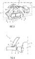
- figure 1 is a schematic view of a detail of an ear mold 1 or hearing aid with a shell 2 and a cover plate 3.
- the earpiece 1 or the hearing aid can also include a transmitter/receiver unit for wireless operation, in particular with an operating frequency in a band from 2.4 GHz to 2.5 GHz, and an antenna 4, in particular a dipole antenna.
- the antenna 4 is integrated into the cover plate 3, in particular so that it follows a contour of a perimeter of the cover plate 3 in order to maximize radiation gains.
- the antenna 4 is arranged around internal components 5, such as a battery 10 and an electronic sub-unit 11, of the earmold 1 or hearing aid.
- the antenna 4 may have two arms with a gap between the ends of the arms, the gap preferably being 0.05 mm to 0.5 mm wide in order to optimize the antenna 4 performance.
- the antenna 4 can be in the form of a conductor track on a flexible printed circuit board which is arranged medial in the cover plate 3 within a trench 6 which is formed circumferentially in the medial surface of the cover plate 3 .
- the shell 2 may be formed of titanium, plastic, or an elastomer, for example, and is bonded to the medial surface of the cover plate 3 with an adhesive 7 such that all of the internal components 5 fit within the shell 2 .
- the trench 6 is outside of all internal components 5 in the cover plate 3.
- the wall 8 prevents the glue 7 from running into the trench 6. This prevents the position and/or shape of the antenna 4 already placed there from being changed, so that the position and/or shape of the antenna 4 can be reproduced for all ear molds 1 produced.
- the wall 8 is placed in particular in such a way that it takes up as little space as possible and is not higher or wider than necessary, but prevents the adhesive 7 from flowing down into the trench 6 .
- the wall 8 is 1 mm high or less. Tests have shown that a range between 0.2 mm and 1 mm is particularly advantageous. With lower ridges, the adhesive is not securely retained. A higher wall is disadvantageous because it takes up more space. Furthermore, the wall 8 can be placed so that it is directly adjacent to the shell 2 when this is glued to the cover plate 3, so that the positioning of the shell 2 on the cover plate 3 is facilitated. After the shell 2 has been glued on, a protruding area of the cover plate 3 can be cut off along an outer edge 9 of the shell 2 pointing radially away from the longitudinal axis L.
- figure 2 is another schematic view of the cover plate 3.
- FIG. 12 is a schematic view of the cover plate 3 with internal components 5 of the eartip 1 mounted thereon, e.g. a battery 10 and an electronic sub-unit 11, e.g. comprising a transceiver unit.
- a loudspeaker 12 is connected to the electronic sub-unit 11 and is located in figure 3 loosely on the area around the cover plate 3 to be cut off after the later gluing of the shell 2 .
- the loudspeaker 12 is arranged in the shell 2 at its medial end, for example before the shell 2 is glued on.
- figure 4 is a schematic view of a detail of another embodiment of an ear tip 1 with a shell 2 and a cover plate 3.
- the earpiece 1 or the hearing aid can also include a transmitter/receiver unit for wireless operation, in particular with an operating frequency in a band from 2.4 GHz to 2.5 GHz, and an antenna 4, in particular a dipole antenna.
- the antenna 4 is integrated into the cover plate 3, in particular so that it follows a contour of a perimeter of the cover plate 3 in order to maximize radiation gains.
- the antenna 4 is arranged around internal components 5, such as a battery 10 and an electronic sub-unit 11, of the earmold 1 or hearing aid.
- the antenna 4 may have two arms with a gap between the arms, the gap preferably being 0.1 mm to 5 mm wide in order to optimize the antenna 4 performance.
- the antenna 4 can be formed as a conductor track on a flexible printed circuit board which is arranged medial in the cover plate 3 within a trench 6 which is formed in the medial surface of the cover plate 3 .
- the shell 2 can be formed, for example, from titanium, plastic or an elastomer and is attached to an adhesive 7 on the medial side of the Cover plate 3 glued so that all internal components 5 fit into shell 2.
- the trench 6 is outside of all internal components 5 in the cover plate 3.
- the wall 8 prevents the glue 7 from running into the trench 6.
- the wall 8 is placed in particular in such a way that it takes up as little space as possible and is not higher or wider than necessary, but prevents the adhesive 7 from flowing down into the trench 6 .
- the wall 8 is 1 mm high or less. Furthermore, the wall 8 can be placed so that it is directly adjacent to the shell 2 when this is glued to the cover plate 3, so that the positioning of the shell 2 on the cover plate 3 is facilitated.
- a protruding area of the cover plate 3 can be cut off along an outer edge 9 of the shell 2 pointing radially away from the longitudinal axis L.
- the shell 2 has to have such a small outside diameter that it cannot easily be glued radially outside of the wall 8 .
- a circumferential recess 13 pointing radially to the longitudinal axis L can be provided in the shell 2 at its lateral end, which is designed in such a way that the wall 8 is at least partially accommodated therein and the remaining part of the lateral end of the shell 2 can still be glued to the cover plate 3.
- the recess 13 can already be formed during the 3D printing of the shell 2 . Alternatively, the recess 13 can be subsequently milled out of the shell 2 .
Landscapes
- Engineering & Computer Science (AREA)
- Physics & Mathematics (AREA)
- Health & Medical Sciences (AREA)
- General Health & Medical Sciences (AREA)
- Neurosurgery (AREA)
- Otolaryngology (AREA)
- Acoustics & Sound (AREA)
- Signal Processing (AREA)
- Manufacturing & Machinery (AREA)
- Computer Networks & Wireless Communication (AREA)
- Telephone Set Structure (AREA)
- Headphones And Earphones (AREA)
- Support Of Aerials (AREA)
Description
- Die Erfindung betrifft eine Abdeckplatte zum Abdecken einer lateralen Öffnung einer Schale eines Ohrpassstücks, das zum Tragen zumindest teilweise in einem Ohrkanal ausgebildet ist. Ferner betrifft die Erfindung ein Ohrpassstück sowie ein Verfahren zur Herstellung eines Ohrpassstücks.
- Ohrpassstücke oder Hörgeräte, die zum Tragen zumindest teilweise in einem Ohrkanal vorgesehen sind, umfassen eine Schale mit einer nach außen weisenden Öffnung, die durch eine Abdeckplatte, die auch als faceplate bezeichnet wird, abgedeckt sind. Im-Ohr-Hörgeräte (ITE - "in the ear") sind Beispiele solcher Hörgeräte, die ein Ohrpassstück aufweisen. Die Schale kann eine standardisierte Form oder eine kundenspezifische Form (das heißt an die individuelle Form des Ohrkanals eines Nutzers angepasst) aufweisen, wobei das Gehäuse oder die Schale eine äußere Öffnung aufweist, die durch eine Abdeckplatte abgedeckt ist, die aus dem Ohrkanal heraus weist, wenn das Im-Ohr-Hörgerät im Ohrkanal getragen wird. Für drahtlose Anwendungen, insbesondere im 2.4 GHz ISM-Band (Industrial, Scientific, and Medical), können Im-Ohr-Hörgeräte mit einer geeigneten Antenne ausgestattet sein. Das Design der Antenne wird durch den verfügbaren, begrenzten Platz, das gewünschte Frequenzband und die Wechselwirkung der elektromagnetischen Strahlung mit dem Gewebe des Nutzers eingeschränkt.
-
EP 3 588 980 A1 offenbart eine ITE-Hörvorrichtung, die ein Gehäuse umfasst, das eine Schale und eine Frontplatte umfasst; elektronische Komponenten, die in dem Gehäuse angeordnet sind und mindestens ein Mikrofon, eine Signalverarbeitungseinheit, einen Lautsprecher, eine Antenne und eine Batterie umfassen; und eine flexible Hauptplatine zum elektrischen Verbinden von mindestens einem Mikrofon, der Signalverarbeitungseinheit und der Batterie, wobei der Lautsprecher mit der flexiblen Hauptplatine durch Litzendrähte verbunden ist, die an Lautsprecherpads der Leiterplatte gelötet sind und eine Länge von 2 mm bis 15 mm aufweisen. -
US 2006/0120547 A1 offenbart ein Hörgerät umfassend eine Frontplatte und eine Schale. Die Frontplatte ist eine runde Platte, die einen in der Oberfläche der Platte definierten Graben und mindestens ein Merkmal aufweist, das der Platte zum Verbinden mit einer Hörgerätekomponente zugeordnet ist. Der Graben ist ein Graben oder Kanal, der in der Oberfläche der Frontplatte definiert ist und eine Wandstruktur zum Koppeln mit einer Hülle eines Hörgeräts enthält. Der Graben kann symmetrisch um das mindestens eine Merkmal definiert sein. Der Graben kann eine ovale Form und einen rechteckigen Querschnitt haben. Auf der Frontplatte befindet sich ein Ausschnitt, mit dem das Herausschneiden von Material aus der Frontplatte beschleunigt werden kann, sobald die Schale mit der Frontplatte verbunden wurde. - Der Erfindung liegt die Aufgabe zu Grunde, eine verbesserte Abdeckplatte für ein Ohrpassstück, das für drahtlose Anwendung geeignet ist, ein Ohrpassstück mit einer solchen Abdeckplatte sowie ein verbessertes Verfahren zur Herstellung eines solchen Ohrpassstücks anzugeben.
- Die Aufgabe wird erfindungsgemäß gelöst durch eine Abdeckplatte mit den Merkmalen des Anspruchs 1, durch ein Ohrpassstück mit den Merkmalen des Anspruchs 5 und durch ein Verfahren mit den Merkmalen des Anspruchs 12.
- Vorteilhafte Ausgestaltungen der Erfindung sind Gegenstand der Unteransprüche.
- Erfindungsgemäß wird eine Abdeckplatte zum Abdecken einer lateralen Öffnung einer Schale eines Ohrpassstücks vorgeschlagen, das zum Tragen zumindest teilweise in einem Ohrkanal ausgebildet ist, wobei die Abdeckplatte auf einer medialen Seite einen umlaufenden Graben zur Aufnahme einer Antenne aufweist, wobei die Abdeckplatte radial außerhalb des Grabens einen umlaufenden Wall und daran anschließend eine Fläche zum Ankleben der Schale aufweist. Unter einem umlaufenden Graben soll in dieser Anmeldung ein Graben verstanden werden, der entweder vollständig umläuft oder eine oder mehrere Unterbrechungen aufweist.
- Der Wall verhindert beim Aufkleben der Schale auf der Abdeckplatte, dass Kleber in den Graben läuft. Auf diese Weise wird verhindert, dass die Lage und/oder Form der dort bereits platzierten Antenne verändert wird, so dass die Lage und/oder Form der Antenne bei allen hergestellten Ohrpassstücken reproduzierbar ist.
- In einer Ausführungsform grenzt der umlaufende Wall direkt an den Graben an. Der Wall ist insbesondere so platziert, dass er möglichst wenig Platz einnimmt und nicht höher und breiter als nötig ist, jedoch das Herunterfließen des Klebers in den Graben verhindert.
- In einer Ausführungsform ist der umlaufende Wall einstückig mit der Abdeckplatte gebildet.
- Erfindungsgemäß ragt der Wall 1 mm hoch oder weniger über die Fläche zum Ankleben der Schale.
- In einer Ausführungsform ist der Graben in der medialen Oberfläche der Abdeckplatte ausgeformt.
- In einer Ausführungsform ist die Abdeckplatte Teil eines Ohrpassstücks, das zum Tragen zumindest teilweise in einem Ohrkanal ausgebildet ist, und ferner eine Schale mit einer lateralen Öffnung umfasst, die durch die Abdeckplatte abgedeckt ist, wobei ein laterales Ende der Schale zumindest auf einer medialen Fläche der Abdeckplatte außerhalb des Walls angeklebt ist.
- In einer Ausführungsform umfasst das Ohrpassstück ferner mindestens eine interne Komponente, umfassend eine Sende/Empfänger-Einheit zum drahtlosen Betrieb, insbesondere mit einer Arbeitsfrequenz in einem Band von 2.4 GHz bis 2.5 GHz, sowie eine Antenne, die im Graben angeordnet ist.
- In einer Ausführungsform ist der Wall so platziert, dass er direkt an die Schale angrenzt, wenn diese auf die Abdeckplatte aufgeklebt ist. Auf diese Weise wird die Positionierung der Schale auf der Abdeckplatte erleichtert.
- In einer Ausführungsform ist am lateralen Ende der Schale eine radial nach innen weisende, umlaufende Ausnehmung vorgesehen, die so ausgebildet ist, dass der Wall zumindest teilweise darin aufgenommen ist und ein verbleibender Teil des lateralen Endes der Schale auf der Abdeckplatte aufgeklebt ist. Diese Ausführungsform löst das Problem, dass insbesondere bei schmalen Ohrkanälen die Schale einen so geringen Außendurchmesser aufweisen muss, dass sie nicht ohne weiteres radial außerhalb des Walls angeklebt werden kann. Die Ausnehmung hilft diesem Problem ab.
- In einer Ausführungsform ist die Antenne als eine Dipolantenne ausgebildet.
- In einer Ausführungsform ist die Antenne als Leiterbahn auf einer flexiblen Leiterplatte ausgebildet.
- In einer Ausführungsform ist die Schale aus Titan, Kunststoff oder einem Elastomer gebildet.
- Gemäß einem Aspekt der vorliegenden Erfindung wird ein Verfahren zum Herstellen eines Ohrpassstücks vorgeschlagen, wobei mindestens eine interne Komponente auf einer medialen Seite der Abdeckplatte und eine Antenne im Graben angeordnet wird, wobei ein laterales Ende der Schale zumindest auf einer medialen Fläche der Abdeckplatte außerhalb des Walls angeklebt wird.
- In einer Ausführungsform wird anschließend an das Aufkleben der Schale ein überstehender Bereich der Abdeckplatte an einer Außenkante der Schale entlang abgeschnitten.
- In einer Ausführungsform wird die Schale mittels 3D-Druck gefertigt und die Ausnehmung wird beim 3D-Druck der Schale ausgebildet wird oder die Ausnehmung wird nachträglich aus der Schale ausgefräst.
- Ausführungsbeispiele der Erfindung werden im Folgenden anhand von Zeichnungen näher erläutert.
- Darin zeigen:
- Figur 1
- eine schematische Schnittansicht eines Details eines Ohrpassstücks mit einer Schale und einer Abdeckplatte,
- Figur 2
- eine schematische Schnittansicht der Abdeckplatte,
- Figur 3
- eine schematische Schnittansicht der Abdeckplatte mit internen Komponenten des Ohrpassstücks, und
- Figur 4
- eine schematische Schnittansicht eines Details einer weiteren Ausführungsform eines Ohrpassstücks mit einer Schale und einer Abdeckplatte.
- Einander entsprechende Teile sind in allen Figuren mit den gleichen Bezugszeichen versehen.
- Im Folgenden soll der Begriff "Hörgerät" alle Arten von Hörgeräten bezeichnen, die ausgebildet sind, zumindest teilweise in einem Ohrkanal getragen zu werden, beispielsweise Im-Ohr-Hörgeräte (ITE), Im-Kanal-Hörgeräte (ITC - In the canal) oder Komplett-im-Kanal-Hörgeräte (CIC - completely in the canal).
- Im Folgenden soll der Begriff "lateral" sich auf eine Richtung beziehen, die vom Trommelfell weg weist, wenn das Hörgerät zumindest teilweise im Ohrkanal getragen wird. Der Begriff "medial" bezieht sich auf eine Richtung zum Trommelfell hin, wenn das Hörgerät zumindest teilweise im Ohrkanal getragen wird.
- Die Erfindung betrifft ein Ohrpassstück 1 oder ein Hörgerät, das zum Tragen zumindest teilweise in einem Ohrkanal vorgesehen ist, insbesondere ein Im-Ohr-Hörgerät (ITE), umfassend eine Schale 2, die zum Tragen zumindest teilweise in einem Ohrkanal vorgesehen ist und eine laterale Öffnung aufweist, die durch eine Abdeckplatte 3 (faceplate) abgedeckt sind.
-
Figur 1 ist eine schematische Ansicht eines Details eines Ohrpassstücks 1 oder Hörgeräts mit einer Schale 2 und einer Abdeckplatte 3. - Das Ohrpassstück 1 oder das Hörgerät kann ferner eine Sende/Empfänger-Einheit zum drahtlosen Betrieb, insbesondere mit einer Arbeitsfrequenz in einem Band von 2.4 GHz bis 2.5 GHz, und eine Antenne 4, insbesondere eine Dipolantenne, umfassen. Die Antenne 4 ist in der Abdeckplatte 3 integriert, insbesondere so, dass sie einer Kontur eines Umfangs der Abdeckplatte 3 folgt, um Strahlungsgewinne zu maximieren.
- In einigen Ausführungsformen ist die Antenne 4 um interne Komponenten 5, beispielsweise eine Batterie 10 und eine elektronische Untereinheit 11, des Ohrpassstücks 1 oder Hörgeräts herum angeordnet. Die Antenne 4 kann zwei Arme mit einer Lücke zwischen den Enden der Arme aufweisen, wobei die Lücke vorzugsweise 0,05 mm bis 0,5 mm breit ist, um die Leistung der Antenne 4 zu optimieren.
- Die Antenne 4 kann als Leiterbahn auf einer flexiblen Leiterplatte ausgebildet sein, die medial in der Abdeckplatte 3 innerhalb eines Grabens 6 angeordnet ist, der in der medialen Oberfläche der Abdeckplatte 3 umlaufend ausgeformt ist. Die Schale 2 kann beispielsweise aus Titan, Kunststoff oder einem Elastomer gebildet sein und wird mit einem Kleber 7 so auf die mediale Oberfläche der Abdeckplatte 3 geklebt, dass alle internen Komponenten 5 in die Schale 2 passen. Der Graben 6 liegt außerhalb aller internen Komponenten 5 in der Abdeckplatte 3. Auf einer radial von einer Längsachse L des Ohrpassstücks 1 oder Hörgeräts wegweisenden Außenseite des Grabens 6 ist auf der medialen Oberfläche der Abdeckplatte 3, beispielsweise direkt an den Graben 6 angrenzend, ein umlaufender Wall 8 vorgesehen, der beispielsweise einstückig mit der Abdeckplatte 3 gebildet sein kann. Der Wall 8 verhindert beim Aufkleben der Schale 2 auf der Abdeckplatte 3, dass Kleber 7 in den Graben 6 läuft. Auf diese Weise wird verhindert, dass die Lage und/oder Form der dort bereits platzierten Antenne 4 verändert wird, so dass die Lage und/oder Form der Antenne 4 bei allen hergestellten Ohrpassstücken 1 reproduzierbar ist. Der Wall 8 ist insbesondere so platziert, dass er möglichst wenig Platz einnimmt und nicht höher und breiter als nötig ist, jedoch das Herunterfließen des Klebers 7 in den Graben 6 verhindert.
- Erfindungsgemäß ist der Wall 8 1 mm hoch oder niedriger. In Versuchen hat sich gezeigt, dass ein Bereich zwischen 0,2 mm und 1 mm besonders vorteilhaft ist. Bei niedrigeren Wällen wird der Klebstoff nicht sicher zurückgehalten. Ein höherer Wall ist nachteilig, weil er mehr Raum beansprucht. Ferner kann der Wall 8 so platziert sein, dass er direkt an die Schale 2 angrenzt, wenn diese auf die Abdeckplatte 3 aufgeklebt ist, so dass die Positionierung der Schale 2 auf der Abdeckplatte 3 erleichtert wird. Anschließend an das Aufkleben der Schale 2 kann ein überstehender Bereich der Abdeckplatte 3 an einer radial von der Längsachse L wegweisenden Außenkante 9 der Schale 2 entlang abgeschnitten werden.
-
Figur 2 ist eine weitere schematische Ansicht der Abdeckplatte 3. -
Figur 3 ist eine schematische Ansicht der Abdeckplatte 3 mit daran montierten internen Komponenten 5 des Ohrpassstücks 1, beispielsweise einer Batterie 10 und einer elektronischen Untereinheit 11, beispielsweise umfassend eine Sende/Empfänger-Einheit. Ein Lautsprecher 12 ist an die elektronische Untereinheit 11 angeschlossen und liegt inFigur 3 lose auf dem nach dem späteren Ankleben der Schale 2 abzuschneidenden Bereich um die Abdeckplatte 3 herum auf. Der Lautsprecher 12 wird beispielsweise vor dem Ankleben der Schale 2 in der Schale 2 an deren medialem Ende angeordnet. -
Figur 4 ist eine schematische Ansicht eines Details einer weiteren Ausführungsform eines Ohrpassstücks 1 mit einer Schale 2 und einer Abdeckplatte 3. - Das Ohrpassstück 1 oder das Hörgerät kann ferner eine Sende/Empfänger-Einheit zum drahtlosen Betrieb, insbesondere mit einer Arbeitsfrequenz in einem Band von 2.4 GHz bis 2.5 GHz, und eine Antenne 4, insbesondere eine Dipolantenne, umfassen. Die Antenne 4 ist in der Abdeckplatte 3 integriert, insbesondere so, dass sie einer Kontur eines Umfangs der Abdeckplatte 3 folgt, um Strahlungsgewinne zu maximieren.
- In einigen Ausführungsformen ist die Antenne 4 um interne Komponenten 5, beispielsweise eine Batterie 10 und eine elektronische Untereinheit 11, des Ohrpassstücks 1 oder Hörgeräts herum angeordnet. Die Antenne 4 kann zwei Arme mit einer Lücke zwischen den Armen aufweisen, wobei die Lücke vorzugsweise 0,1 mm bis 5 mm breit ist, um die Leistung der Antenne 4 zu optimieren.
- Die Antenne 4 kann als Leiterbahn auf einer flexiblen Leiterplatte ausgebildet sein, die medial in der Abdeckplatte 3 innerhalb eines Grabens 6 angeordnet ist, der in der medialen Oberfläche der Abdeckplatte 3 ausgeformt ist.
- Die Schale 2 kann beispielsweise aus Titan, Kunststoff oder einem Elastomer gebildet sein und wird mit einem Kleber 7 so auf die mediale Seite der Abdeckplatte 3 geklebt, dass alle internen Komponenten 5 in die Schale 2 passen. Der Graben 6 liegt außerhalb aller internen Komponenten 5 in der Abdeckplatte 3. Auf einer radial von einer Längsachse L des Ohrpassstücks 1 oder Hörgeräts wegweisenden Außenseite des Grabens 6 ist auf der medialen Seite der Abdeckplatte 3, beispielsweise direkt an den Graben 6 angrenzend, ein umlaufender Wall 8 vorgesehen, der beispielsweise einstückig mit der Abdeckplatte 3 gebildet sein kann. Der Wall 8 verhindert beim Aufkleben der Schale 2 auf der Abdeckplatte 3, dass Kleber 7 in den Graben 6 läuft. Auf diese Weise wird verhindert, dass die Lage und/oder Form der dort bereits platzierten Antenne 4 verändert wird, so dass die Lage und/oder Form der Antenne 4 bei allen hergestellten Ohrpassstücken 1 reproduzierbar ist. Der Wall 8 ist insbesondere so platziert, dass er möglichst wenig Platz einnimmt und nicht höher und breiter als nötig ist, jedoch das Herunterfließen des Klebers 7 in den Graben 6 verhindert. Erfindungsgemäß ist der Wall 8 1 mm hoch oder niedriger. Ferner kann der Wall 8 so platziert sein, dass er direkt an die Schale 2 angrenzt, wenn diese auf die Abdeckplatte 3 aufgeklebt ist, so dass die Positionierung der Schale 2 auf der Abdeckplatte 3 erleichtert wird. Anschließend an das Aufkleben der Schale 2 kann ein überstehender Bereich der Abdeckplatte 3 an einer radial von der Längsachse L wegweisenden Außenkante 9 der Schale 2 entlang abgeschnitten werden. Insbesondere bei schmalen Ohrkanälen kann es vorkommen, dass die Schale 2 einen so geringen Außendurchmesser aufweisen muss, dass sie nicht ohne weiteres radial außerhalb des Walls 8 angeklebt werden kann. Um dem abzuhelfen, kann in der Schale 2 an deren lateralem Ende eine radial zur Längsachse L hinweisende, umlaufende Ausnehmung 13 vorgesehen sein, die so ausgebildet ist, dass der Wall 8 zumindest zum Teil darin aufgenommen werden und der verbleibende Teil des lateralen Endes der Schale 2 trotzdem auf der Abdeckplatte 3 aufgeklebt werden kann. Die Ausnehmung 13 kann bereits beim 3D-Drucken der Schale 2 ausgebildet werden. Alternativ kann die Ausnehmung 13 nachträglich aus der Schale 2 ausgefräst werden.
-
- 1
- Ohrpassstück
- 2
- Schale
- 3
- Abdeckplatte
- 4
- Antenne
- 5
- Interne Komponente
- 6
- Graben
- 7
- Kleber
- 8
- Wall
- 9
- Außenkante
- 10
- Batterie
- 11
- Elektronische Untereinheit
- 12
- Lautsprecher
- 13
- Ausnehmung
- L
- Längsachse
Claims (14)
- Abdeckplatte (3) zum Abdecken einer lateralen Öffnung einer Schale (2) eines Ohrpassstücks (1), das zum Tragen zumindest teilweise in einem Ohrkanal ausgebildet ist, wobei die Abdeckplatte (3) auf einer medialen Seite einen umlaufenden Graben (6) zur Aufnahme einer Antenne (4) aufweist, wobei die Abdeckplatte (3) radial außerhalb des Grabens (6) einen umlaufenden Wall (8) und daran anschließend eine Fläche zum Ankleben der Schale (2) aufweist, dadurch gekennzeichnet, dass der Wall (8) 1 mm hoch oder weniger über die Fläche zum Ankleben der Schale (2) ragt.
- Abdeckplatte (3) nach Anspruch 1, wobei der umlaufende Wall (8) direkt an den Graben (6) angrenzt.
- Abdeckplatte (3) nach Anspruch 1 oder 2, wobei der umlaufende Wall (8) einstückig mit der Abdeckplatte (3) gebildet ist.
- Abdeckplatte (3) nach einem der vorhergehenden Ansprüche, wobei der Graben (6) in der medialen Oberfläche der Abdeckplatte (3) ausgeformt ist.
- Ohrpassstück (1), das zum Tragen zumindest teilweise in einem Ohrkanal ausgebildet ist, umfassend eine Abdeckplatte (3) nach einem der vorhergehenden Ansprüche, eine Schale (2) mit einer lateralen Öffnung, die durch die Abdeckplatte (3) abgedeckt ist, wobei ein laterales Ende der Schale (2) zumindest auf einer medialen Fläche der Abdeckplatte (3) außerhalb des Walls (8) angeklebt ist.
- Ohrpassstück (1) nach Anspruch 5, ferner umfassend mindestens eine interne Komponente (5), umfassend eine Sende/Empfänger-Einheit zum drahtlosen Betrieb, insbesondere mit einer Arbeitsfrequenz in einem Band von 2.4 GHz bis 2.5 GHz, sowie eine Antenne (4), die im Graben (6) angeordnet ist.
- Ohrpassstück (1) nach einem der Ansprüche 5 oder 6, wobei der Wall (8) so platziert ist, dass er direkt an die Schale (2) angrenzt, wenn diese auf die Abdeckplatte (3) aufgeklebt ist.
- Ohrpassstück (1) nach einem der Ansprüche 5 bis 7, wobei am lateralen Ende der Schale (2) eine radial nach innen weisende, umlaufende Ausnehmung (13) vorgesehen ist, die so ausgebildet ist, dass der Wall (8) darin zumindest zum Teil aufgenommen ist und ein verbleibender Teil des lateralen Endes der Schale (2) auf der Abdeckplatte (3) aufgeklebt ist.
- Ohrpassstück (1) nach einem der Ansprüche 6 bis 8, wobei die Antenne (4) als eine Dipolantenne ausgebildet ist.
- Ohrpassstück (1) nach einem der Ansprüche 6 bis 9, wobei die Antenne (4) als Leiterbahn auf einer flexiblen Leiterplatte ausgebildet ist.
- Ohrpassstück (1) nach einem der Ansprüche 5 bis 10, wobei die Schale (2) aus Titan, Kunststoff oder einem Elastomer gebildet ist.
- Verfahren zum Herstellen eines Ohrpassstücks (1) nach einem der Ansprüche 5 bis 11, wobei mindestens eine interne Komponente (5) auf einer medialen Seite der Abdeckplatte (3) und eine Antenne (4) im Graben (6) angeordnet wird, wobei ein laterales Ende der Schale (2) zumindest auf einer medialen Fläche der Abdeckplatte (3) außerhalb des Walls (8) angeklebt wird.
- Verfahren nach Anspruch 12, wobei anschließend an das Aufkleben der Schale (2) ein überstehender Bereich der Abdeckplatte (3) an einer Außenkante (9) der Schale (2) entlang abgeschnitten wird.
- Verfahren nach einem der Ansprüche 12 oder 13, wobei die Schale (2) mittels 3D-Druck gefertigt wird und die Ausnehmung (13) beim 3D-Druck der Schale (2) ausgebildet wird oder wobei die Ausnehmung (13) nachträglich aus der Schale (2) ausgefräst wird.
Priority Applications (3)
| Application Number | Priority Date | Filing Date | Title |
|---|---|---|---|
| EP20155132.2A EP3860152B1 (de) | 2020-02-03 | 2020-02-03 | Abdeckplatte für ein ohrpassstück, ohrpassstück und verfahren zu dessen herstellung |
| CN202120108659.4U CN214256603U (zh) | 2020-02-03 | 2021-01-15 | 用于耳件的盖板及耳件 |
| US17/161,542 US11523235B2 (en) | 2020-02-03 | 2021-01-28 | Cover plate for an earpiece, earpiece and method of producing earpiece |
Applications Claiming Priority (1)
| Application Number | Priority Date | Filing Date | Title |
|---|---|---|---|
| EP20155132.2A EP3860152B1 (de) | 2020-02-03 | 2020-02-03 | Abdeckplatte für ein ohrpassstück, ohrpassstück und verfahren zu dessen herstellung |
Publications (2)
| Publication Number | Publication Date |
|---|---|
| EP3860152A1 EP3860152A1 (de) | 2021-08-04 |
| EP3860152B1 true EP3860152B1 (de) | 2022-04-27 |
Family
ID=69467408
Family Applications (1)
| Application Number | Title | Priority Date | Filing Date |
|---|---|---|---|
| EP20155132.2A Active EP3860152B1 (de) | 2020-02-03 | 2020-02-03 | Abdeckplatte für ein ohrpassstück, ohrpassstück und verfahren zu dessen herstellung |
Country Status (3)
| Country | Link |
|---|---|
| US (1) | US11523235B2 (de) |
| EP (1) | EP3860152B1 (de) |
| CN (1) | CN214256603U (de) |
Families Citing this family (1)
| Publication number | Priority date | Publication date | Assignee | Title |
|---|---|---|---|---|
| US10051388B2 (en) | 2016-09-21 | 2018-08-14 | Starkey Laboratories, Inc. | Radio frequency antenna for an in-the-ear hearing device |
Family Cites Families (7)
| Publication number | Priority date | Publication date | Assignee | Title |
|---|---|---|---|---|
| US7409069B2 (en) * | 2004-12-03 | 2008-08-05 | Sound Design Technologies, Ltd. | Faceplate moat and cut out for hearing instrument |
| US7832080B2 (en) * | 2007-10-11 | 2010-11-16 | Etymotic Research, Inc. | Directional microphone assembly |
| US8494197B2 (en) * | 2008-12-19 | 2013-07-23 | Starkey Laboratories, Inc. | Antennas for custom fit hearing assistance devices |
| CN105493523B (zh) * | 2013-06-19 | 2019-11-15 | 奥托特罗尼克斯有限责任公司 | 用于电磁听力植入物中的线圈对准的改进的方法和装置 |
| EP3326388B1 (de) * | 2015-07-17 | 2021-01-27 | Sonova AG | Hörgerät zum zumindest teilweisen tragen innerhalb eines ohrkanals und verfahren zur herstellung solch eines hörgeräts |
| US10051388B2 (en) * | 2016-09-21 | 2018-08-14 | Starkey Laboratories, Inc. | Radio frequency antenna for an in-the-ear hearing device |
| EP3588980B1 (de) * | 2018-06-25 | 2021-06-02 | Sonova AG | Ite-hörgerät |
-
2020
- 2020-02-03 EP EP20155132.2A patent/EP3860152B1/de active Active
-
2021
- 2021-01-15 CN CN202120108659.4U patent/CN214256603U/zh active Active
- 2021-01-28 US US17/161,542 patent/US11523235B2/en active Active
Also Published As
| Publication number | Publication date |
|---|---|
| EP3860152A1 (de) | 2021-08-04 |
| US11523235B2 (en) | 2022-12-06 |
| US20210243541A1 (en) | 2021-08-05 |
| CN214256603U (zh) | 2021-09-21 |
Similar Documents
| Publication | Publication Date | Title |
|---|---|---|
| EP2932559B1 (de) | Modulare antenne für hörgeräte | |
| EP2932560B2 (de) | Faltdipol für hörhilfegeräte | |
| EP2782363B1 (de) | Binaurales Hörinstrument sowie Ohrstück | |
| DE19829637C2 (de) | Medizinisches Implantat | |
| EP1583395B1 (de) | IdO-Hörgerät zur binauralen Versorgung eines Patienten | |
| EP3101918B1 (de) | Hörgerät | |
| EP3567672B1 (de) | Hörhilfegerät mit elektronikrahmen und darin integrierter antenne | |
| DE212024000221U1 (de) | Ohrclip-Kopfhörer | |
| DE102017219882B3 (de) | Hörgerät | |
| EP1349425B1 (de) | Platzierung eines elektroakustischen Miniaturwandlers in einem Hörgerät | |
| EP4258694A1 (de) | Hörgerät, insbesondere in-dem-ohr-hörgerät | |
| EP3322032A1 (de) | Hörhilfegerät mit elektronikrahmen und darin integrierter antenne | |
| EP3860152B1 (de) | Abdeckplatte für ein ohrpassstück, ohrpassstück und verfahren zu dessen herstellung | |
| EP4054208B1 (de) | Hörgerät, antenne für ein hörgerät und verfahren zur herstellung eines hörgeräts | |
| DE102016207844A1 (de) | Hörgerät | |
| DE212023000454U1 (de) | Kopfhörer | |
| EP0660642B1 (de) | Am Kopf tragbares Hörgerät | |
| DE3428166A1 (de) | Im gehoergang zu tragendes hoergeraet fuer schwerhoerige oder hoerbehinderte | |
| EP3826327A1 (de) | Hörgerät | |
| CH643414A5 (en) | Hearing-aid with plug device | |
| EP3863305B1 (de) | Hörgerät | |
| EP2911312B1 (de) | Antenne mit Schirmvorrichtung und Herstellungsverfahren | |
| EP3396979B1 (de) | Verfahren zur herstellung eines tragrahmens eines hörhilfegeräts und tragrahmen sowie hörhilfegerät | |
| DE102017210448B3 (de) | Hörgerät | |
| DE102017220187A1 (de) | Hörhilfegerät |
Legal Events
| Date | Code | Title | Description |
|---|---|---|---|
| PUAI | Public reference made under article 153(3) epc to a published international application that has entered the european phase |
Free format text: ORIGINAL CODE: 0009012 |
|
| STAA | Information on the status of an ep patent application or granted ep patent |
Free format text: STATUS: REQUEST FOR EXAMINATION WAS MADE |
|
| 17P | Request for examination filed |
Effective date: 20201103 |
|
| AK | Designated contracting states |
Kind code of ref document: A1 Designated state(s): AL AT BE BG CH CY CZ DE DK EE ES FI FR GB GR HR HU IE IS IT LI LT LU LV MC MK MT NL NO PL PT RO RS SE SI SK SM TR |
|
| RIC1 | Information provided on ipc code assigned before grant |
Ipc: H04R 1/10 20060101ALN20211028BHEP Ipc: H04R 25/02 20060101ALN20211028BHEP Ipc: H04R 25/00 20060101AFI20211028BHEP |
|
| GRAP | Despatch of communication of intention to grant a patent |
Free format text: ORIGINAL CODE: EPIDOSNIGR1 |
|
| STAA | Information on the status of an ep patent application or granted ep patent |
Free format text: STATUS: GRANT OF PATENT IS INTENDED |
|
| INTG | Intention to grant announced |
Effective date: 20211203 |
|
| GRAS | Grant fee paid |
Free format text: ORIGINAL CODE: EPIDOSNIGR3 |
|
| GRAA | (expected) grant |
Free format text: ORIGINAL CODE: 0009210 |
|
| STAA | Information on the status of an ep patent application or granted ep patent |
Free format text: STATUS: THE PATENT HAS BEEN GRANTED |
|
| AK | Designated contracting states |
Kind code of ref document: B1 Designated state(s): AL AT BE BG CH CY CZ DE DK EE ES FI FR GB GR HR HU IE IS IT LI LT LU LV MC MK MT NL NO PL PT RO RS SE SI SK SM TR |
|
| REG | Reference to a national code |
Ref country code: GB Ref legal event code: FG4D Free format text: NOT ENGLISH |
|
| REG | Reference to a national code |
Ref country code: CH Ref legal event code: EP |
|
| REG | Reference to a national code |
Ref country code: DE Ref legal event code: R096 Ref document number: 502020000982 Country of ref document: DE |
|
| REG | Reference to a national code |
Ref country code: AT Ref legal event code: REF Ref document number: 1487909 Country of ref document: AT Kind code of ref document: T Effective date: 20220515 |
|
| REG | Reference to a national code |
Ref country code: IE Ref legal event code: FG4D Free format text: LANGUAGE OF EP DOCUMENT: GERMAN |
|
| REG | Reference to a national code |
Ref country code: LT Ref legal event code: MG9D |
|
| REG | Reference to a national code |
Ref country code: NL Ref legal event code: MP Effective date: 20220427 |
|
| PG25 | Lapsed in a contracting state [announced via postgrant information from national office to epo] |
Ref country code: NL Free format text: LAPSE BECAUSE OF FAILURE TO SUBMIT A TRANSLATION OF THE DESCRIPTION OR TO PAY THE FEE WITHIN THE PRESCRIBED TIME-LIMIT Effective date: 20220427 |
|
| PG25 | Lapsed in a contracting state [announced via postgrant information from national office to epo] |
Ref country code: SE Free format text: LAPSE BECAUSE OF FAILURE TO SUBMIT A TRANSLATION OF THE DESCRIPTION OR TO PAY THE FEE WITHIN THE PRESCRIBED TIME-LIMIT Effective date: 20220427 Ref country code: PT Free format text: LAPSE BECAUSE OF FAILURE TO SUBMIT A TRANSLATION OF THE DESCRIPTION OR TO PAY THE FEE WITHIN THE PRESCRIBED TIME-LIMIT Effective date: 20220829 Ref country code: NO Free format text: LAPSE BECAUSE OF FAILURE TO SUBMIT A TRANSLATION OF THE DESCRIPTION OR TO PAY THE FEE WITHIN THE PRESCRIBED TIME-LIMIT Effective date: 20220727 Ref country code: LT Free format text: LAPSE BECAUSE OF FAILURE TO SUBMIT A TRANSLATION OF THE DESCRIPTION OR TO PAY THE FEE WITHIN THE PRESCRIBED TIME-LIMIT Effective date: 20220427 Ref country code: HR Free format text: LAPSE BECAUSE OF FAILURE TO SUBMIT A TRANSLATION OF THE DESCRIPTION OR TO PAY THE FEE WITHIN THE PRESCRIBED TIME-LIMIT Effective date: 20220427 Ref country code: GR Free format text: LAPSE BECAUSE OF FAILURE TO SUBMIT A TRANSLATION OF THE DESCRIPTION OR TO PAY THE FEE WITHIN THE PRESCRIBED TIME-LIMIT Effective date: 20220728 Ref country code: FI Free format text: LAPSE BECAUSE OF FAILURE TO SUBMIT A TRANSLATION OF THE DESCRIPTION OR TO PAY THE FEE WITHIN THE PRESCRIBED TIME-LIMIT Effective date: 20220427 Ref country code: BG Free format text: LAPSE BECAUSE OF FAILURE TO SUBMIT A TRANSLATION OF THE DESCRIPTION OR TO PAY THE FEE WITHIN THE PRESCRIBED TIME-LIMIT Effective date: 20220727 |
|
| PG25 | Lapsed in a contracting state [announced via postgrant information from national office to epo] |
Ref country code: RS Free format text: LAPSE BECAUSE OF FAILURE TO SUBMIT A TRANSLATION OF THE DESCRIPTION OR TO PAY THE FEE WITHIN THE PRESCRIBED TIME-LIMIT Effective date: 20220427 Ref country code: PL Free format text: LAPSE BECAUSE OF FAILURE TO SUBMIT A TRANSLATION OF THE DESCRIPTION OR TO PAY THE FEE WITHIN THE PRESCRIBED TIME-LIMIT Effective date: 20220427 Ref country code: LV Free format text: LAPSE BECAUSE OF FAILURE TO SUBMIT A TRANSLATION OF THE DESCRIPTION OR TO PAY THE FEE WITHIN THE PRESCRIBED TIME-LIMIT Effective date: 20220427 Ref country code: IS Free format text: LAPSE BECAUSE OF FAILURE TO SUBMIT A TRANSLATION OF THE DESCRIPTION OR TO PAY THE FEE WITHIN THE PRESCRIBED TIME-LIMIT Effective date: 20220827 |
|
| REG | Reference to a national code |
Ref country code: DE Ref legal event code: R097 Ref document number: 502020000982 Country of ref document: DE |
|
| PG25 | Lapsed in a contracting state [announced via postgrant information from national office to epo] |
Ref country code: SM Free format text: LAPSE BECAUSE OF FAILURE TO SUBMIT A TRANSLATION OF THE DESCRIPTION OR TO PAY THE FEE WITHIN THE PRESCRIBED TIME-LIMIT Effective date: 20220427 Ref country code: SK Free format text: LAPSE BECAUSE OF FAILURE TO SUBMIT A TRANSLATION OF THE DESCRIPTION OR TO PAY THE FEE WITHIN THE PRESCRIBED TIME-LIMIT Effective date: 20220427 Ref country code: RO Free format text: LAPSE BECAUSE OF FAILURE TO SUBMIT A TRANSLATION OF THE DESCRIPTION OR TO PAY THE FEE WITHIN THE PRESCRIBED TIME-LIMIT Effective date: 20220427 Ref country code: ES Free format text: LAPSE BECAUSE OF FAILURE TO SUBMIT A TRANSLATION OF THE DESCRIPTION OR TO PAY THE FEE WITHIN THE PRESCRIBED TIME-LIMIT Effective date: 20220427 Ref country code: EE Free format text: LAPSE BECAUSE OF FAILURE TO SUBMIT A TRANSLATION OF THE DESCRIPTION OR TO PAY THE FEE WITHIN THE PRESCRIBED TIME-LIMIT Effective date: 20220427 Ref country code: DK Free format text: LAPSE BECAUSE OF FAILURE TO SUBMIT A TRANSLATION OF THE DESCRIPTION OR TO PAY THE FEE WITHIN THE PRESCRIBED TIME-LIMIT Effective date: 20220427 Ref country code: CZ Free format text: LAPSE BECAUSE OF FAILURE TO SUBMIT A TRANSLATION OF THE DESCRIPTION OR TO PAY THE FEE WITHIN THE PRESCRIBED TIME-LIMIT Effective date: 20220427 |
|
| PLBE | No opposition filed within time limit |
Free format text: ORIGINAL CODE: 0009261 |
|
| STAA | Information on the status of an ep patent application or granted ep patent |
Free format text: STATUS: NO OPPOSITION FILED WITHIN TIME LIMIT |
|
| PG25 | Lapsed in a contracting state [announced via postgrant information from national office to epo] |
Ref country code: AL Free format text: LAPSE BECAUSE OF FAILURE TO SUBMIT A TRANSLATION OF THE DESCRIPTION OR TO PAY THE FEE WITHIN THE PRESCRIBED TIME-LIMIT Effective date: 20220427 |
|
| 26N | No opposition filed |
Effective date: 20230130 |
|
| PG25 | Lapsed in a contracting state [announced via postgrant information from national office to epo] |
Ref country code: MC Free format text: LAPSE BECAUSE OF FAILURE TO SUBMIT A TRANSLATION OF THE DESCRIPTION OR TO PAY THE FEE WITHIN THE PRESCRIBED TIME-LIMIT Effective date: 20220427 |
|
| REG | Reference to a national code |
Ref country code: CH Ref legal event code: PL |
|
| REG | Reference to a national code |
Ref country code: BE Ref legal event code: MM Effective date: 20230228 |
|
| PG25 | Lapsed in a contracting state [announced via postgrant information from national office to epo] |
Ref country code: LU Free format text: LAPSE BECAUSE OF NON-PAYMENT OF DUE FEES Effective date: 20230203 Ref country code: LI Free format text: LAPSE BECAUSE OF NON-PAYMENT OF DUE FEES Effective date: 20230228 Ref country code: CH Free format text: LAPSE BECAUSE OF NON-PAYMENT OF DUE FEES Effective date: 20230228 |
|
| REG | Reference to a national code |
Ref country code: IE Ref legal event code: MM4A |
|
| PG25 | Lapsed in a contracting state [announced via postgrant information from national office to epo] |
Ref country code: IT Free format text: LAPSE BECAUSE OF FAILURE TO SUBMIT A TRANSLATION OF THE DESCRIPTION OR TO PAY THE FEE WITHIN THE PRESCRIBED TIME-LIMIT Effective date: 20220427 Ref country code: IE Free format text: LAPSE BECAUSE OF NON-PAYMENT OF DUE FEES Effective date: 20230203 |
|
| PG25 | Lapsed in a contracting state [announced via postgrant information from national office to epo] |
Ref country code: BE Free format text: LAPSE BECAUSE OF NON-PAYMENT OF DUE FEES Effective date: 20230228 |
|
| PG25 | Lapsed in a contracting state [announced via postgrant information from national office to epo] |
Ref country code: BG Free format text: LAPSE BECAUSE OF FAILURE TO SUBMIT A TRANSLATION OF THE DESCRIPTION OR TO PAY THE FEE WITHIN THE PRESCRIBED TIME-LIMIT Effective date: 20220427 |
|
| PG25 | Lapsed in a contracting state [announced via postgrant information from national office to epo] |
Ref country code: BG Free format text: LAPSE BECAUSE OF FAILURE TO SUBMIT A TRANSLATION OF THE DESCRIPTION OR TO PAY THE FEE WITHIN THE PRESCRIBED TIME-LIMIT Effective date: 20220427 |
|
| PGFP | Annual fee paid to national office [announced via postgrant information from national office to epo] |
Ref country code: AT Payment date: 20250417 Year of fee payment: 5 |
|
| PG25 | Lapsed in a contracting state [announced via postgrant information from national office to epo] |
Ref country code: CY Free format text: LAPSE BECAUSE OF FAILURE TO SUBMIT A TRANSLATION OF THE DESCRIPTION OR TO PAY THE FEE WITHIN THE PRESCRIBED TIME-LIMIT; INVALID AB INITIO Effective date: 20200203 |
|
| PG25 | Lapsed in a contracting state [announced via postgrant information from national office to epo] |
Ref country code: HU Free format text: LAPSE BECAUSE OF FAILURE TO SUBMIT A TRANSLATION OF THE DESCRIPTION OR TO PAY THE FEE WITHIN THE PRESCRIBED TIME-LIMIT; INVALID AB INITIO Effective date: 20200203 |
|
| PG25 | Lapsed in a contracting state [announced via postgrant information from national office to epo] |
Ref country code: TR Free format text: LAPSE BECAUSE OF FAILURE TO SUBMIT A TRANSLATION OF THE DESCRIPTION OR TO PAY THE FEE WITHIN THE PRESCRIBED TIME-LIMIT Effective date: 20220427 |
|
| PG25 | Lapsed in a contracting state [announced via postgrant information from national office to epo] |
Ref country code: SI Free format text: LAPSE BECAUSE OF FAILURE TO SUBMIT A TRANSLATION OF THE DESCRIPTION OR TO PAY THE FEE WITHIN THE PRESCRIBED TIME-LIMIT Effective date: 20220427 |
|
| PGFP | Annual fee paid to national office [announced via postgrant information from national office to epo] |
Ref country code: GB Payment date: 20260227 Year of fee payment: 7 |
|
| PGFP | Annual fee paid to national office [announced via postgrant information from national office to epo] |
Ref country code: DE Payment date: 20260227 Year of fee payment: 7 |
|
| PG25 | Lapsed in a contracting state [announced via postgrant information from national office to epo] |
Ref country code: AT Free format text: LAPSE BECAUSE OF NON-PAYMENT OF DUE FEES Effective date: 20250203 |
|
| REG | Reference to a national code |
Ref country code: AT Ref legal event code: MM01 Ref document number: 1487909 Country of ref document: AT Kind code of ref document: T Effective date: 20250203 |
|
| PGFP | Annual fee paid to national office [announced via postgrant information from national office to epo] |
Ref country code: FR Payment date: 20260225 Year of fee payment: 7 |