EP3860307B1 - Système doté d'une plaque de cuisson et d'un ustensile de cuisson et procédé de fonctionnement dudit système - Google Patents
Système doté d'une plaque de cuisson et d'un ustensile de cuisson et procédé de fonctionnement dudit système Download PDFInfo
- Publication number
- EP3860307B1 EP3860307B1 EP21152548.0A EP21152548A EP3860307B1 EP 3860307 B1 EP3860307 B1 EP 3860307B1 EP 21152548 A EP21152548 A EP 21152548A EP 3860307 B1 EP3860307 B1 EP 3860307B1
- Authority
- EP
- European Patent Office
- Prior art keywords
- cooking utensil
- induction heating
- control
- hob
- cookware
- Prior art date
- Legal status (The legal status is an assumption and is not a legal conclusion. Google has not performed a legal analysis and makes no representation as to the accuracy of the status listed.)
- Active
Links
Images

Classifications
-
- H—ELECTRICITY
- H05—ELECTRIC TECHNIQUES NOT OTHERWISE PROVIDED FOR
- H05B—ELECTRIC HEATING; ELECTRIC LIGHT SOURCES NOT OTHERWISE PROVIDED FOR; CIRCUIT ARRANGEMENTS FOR ELECTRIC LIGHT SOURCES, IN GENERAL
- H05B6/00—Heating by electric, magnetic or electromagnetic fields
- H05B6/02—Induction heating
- H05B6/06—Control, e.g. of temperature, of power
- H05B6/062—Control, e.g. of temperature, of power for cooking plates or the like
-
- H—ELECTRICITY
- H05—ELECTRIC TECHNIQUES NOT OTHERWISE PROVIDED FOR
- H05B—ELECTRIC HEATING; ELECTRIC LIGHT SOURCES NOT OTHERWISE PROVIDED FOR; CIRCUIT ARRANGEMENTS FOR ELECTRIC LIGHT SOURCES, IN GENERAL
- H05B2213/00—Aspects relating both to resistive heating and to induction heating, covered by H05B3/00 and H05B6/00
- H05B2213/06—Cook-top or cookware capable of communicating with each other
-
- H—ELECTRICITY
- H05—ELECTRIC TECHNIQUES NOT OTHERWISE PROVIDED FOR
- H05B—ELECTRIC HEATING; ELECTRIC LIGHT SOURCES NOT OTHERWISE PROVIDED FOR; CIRCUIT ARRANGEMENTS FOR ELECTRIC LIGHT SOURCES, IN GENERAL
- H05B2213/00—Aspects relating both to resistive heating and to induction heating, covered by H05B3/00 and H05B6/00
- H05B2213/07—Heating plates with temperature control means
-
- Y—GENERAL TAGGING OF NEW TECHNOLOGICAL DEVELOPMENTS; GENERAL TAGGING OF CROSS-SECTIONAL TECHNOLOGIES SPANNING OVER SEVERAL SECTIONS OF THE IPC; TECHNICAL SUBJECTS COVERED BY FORMER USPC CROSS-REFERENCE ART COLLECTIONS [XRACs] AND DIGESTS
- Y02—TECHNOLOGIES OR APPLICATIONS FOR MITIGATION OR ADAPTATION AGAINST CLIMATE CHANGE
- Y02B—CLIMATE CHANGE MITIGATION TECHNOLOGIES RELATED TO BUILDINGS, e.g. HOUSING, HOUSE APPLIANCES OR RELATED END-USER APPLICATIONS
- Y02B40/00—Technologies aiming at improving the efficiency of home appliances, e.g. induction cooking or efficient technologies for refrigerators, freezers or dish washers
Definitions
- the invention relates to a system with a hob and a cooking utensil that is to be heated on the hob.
- the invention also relates to a method for operating the system, specifically for inductively heating the cooking utensil with the hob.
- the cooking utensil has a cooking utensil control that is to be linked to an induction heating device of the hob as an assignment, which is advantageously done by a cooking utensil control.
- a cooking system with a hob with several cooking zones and a cooking vessel is known. There is a structure-borne sound generator on the hob and a structure-borne sound sensor on the cooking vessel. This enables communication between the two. If each cooking zone is assigned its own structure-borne sound generator, then by placing the cooking vessel directly above it on the structure-borne sound sensor of this cooking vessel, structure-borne sound signals that have been emitted by this cooking zone can be detected. In this way, for example, a specific cooking vessel can be directly and precisely assigned to a specific cooking zone in order to then heat this exact cooking vessel in the desired manner using a heating device on this cooking zone.
- a cookware can be placed on a hob with several cooking zones including heating devices. Each cookware has a temperature sensor and a transmitter. The hob itself has a receiver to to be able to recognize the temperature data sent by the temperature sensors.
- a top-mounted device that can be operated on a hob with a cooking area that has an induction heating coil.
- the top-mounted device has a receiving coil in it.
- the induction heating coil can be used to inductively heat the base of the top-mounted device in order to heat the food inside.
- a voltage can be induced in the receiving coil that can supply a control of the top-mounted device with electrical energy.
- it can also be used to operate a motor for a mixing function if the top-mounted device is designed as a mixer.
- the invention is based on the object of creating a system as mentioned at the beginning and a method as mentioned at the beginning, with which problems of the prior art can be solved and in particular it is possible to assign a specific item of cookware to a specific induction heating device simply and reliably.
- This object is achieved by a system with the features of claim 1 and by a method with the features of claim 11.
- Advantageous and preferred embodiments of the invention are contained in the further claims and are explained in more detail below. Some of the features are described only for the system or only for the method. However, regardless of this, they should be able to apply to both a system and a method independently and independently of one another.
- the wording of the claims is made part of the content of the description by express reference.
- the system has a hob and at least one induction heating device on the hob, advantageously several induction heating devices.
- the system also has a cookware that is placed on the hob and is to be heated inductively for cooking or preparing food in it.
- the hob has a hob plate and at least one induction heating device underneath the hob plate, with which the cookware can be heated inductively.
- Such an induction heating device can advantageously be designed as known in the prior art.
- Several induction heating devices, in particular induction heating coils, can also be provided to jointly form a so-called cooking area for inductively heating a single cookware. This does not change the advantageous usability of the method according to the invention; it can then be carried out for a single, for some or for all induction heating devices of this cooking area.
- the hob also has a hob control and a communication device connected to it for wireless communication with the cookware.
- the wireless communication advantageously takes place using a conventional radio standard, for example WLAN, Bluetooth, BLE, Zigbee or the like.
- the hob also has a power supply for the at least one induction heating device, which is also connected to the hob control and in particular receives specifications from the hob control for power generation at the induction heating device.
- These power specifications can be generated by an operator input on a control device on the hob, or alternatively by an automatically running cooking program or similar.
- the cookware in turn has a vibration sensor for detecting vibrations on the cookware, for which purpose the vibration sensor is attached or mounted on the cookware. Options for this will be explained later, but in any case the vibration sensor is arranged on the cookware in such a way that it can detect vibrations of the cookware or on the cookware. Such a vibration sensor can be based, for example, on a piezoelectric effect or MEMS technology.
- the cookware also has a cookware control that is connected to the vibration sensor and can detect its sensor signals. In particular, it can detect the frequency and/or strength of the vibrations.
- a communication device of the cookware is connected to the cookware control, which is designed for wireless communication with the communication device of the hob, so that at least information or signals can be sent from the cookware to the hob, advantageously also bidirectionally.
- the hob control is designed to carry out a method in which the induction heating device is controlled by means of the power supply with a certain predetermined temporal pattern of power generation.
- This certain temporal pattern is then advantageously characteristic of exactly this induction heating device.
- the temporal pattern of power generation advantageously has a temporal variation and possibly also a variation in the level of power generation; it is particularly advantageous to differentiate based on signals that are different or offset in time. These can be recognized particularly well.
- the induction heating device therefore implements this predetermined temporal pattern for power generation and works according to this pattern or generates inductive fields according to this pattern, advantageously only for a short time in each case as a type of pulse or ping.
- a separate temporal pattern can be specified for each induction heating device of the hob.
- the pattern can also be a coding or correspond to a coding or a code.
- the power is transferred inductively to the cookware, even if it is advantageously low.
- This is known to cause the cookware to oscillate at a certain frequency, but usually at a frequency below the operating frequency of the induction heating device, which can often be between 15 kHz and 30 kHz.
- the vibration sensor records these oscillations or vibrations on the cookware, specifically in terms of their duration or the duration of pauses in between, and possibly also in terms of the height or strength of the vibrations. The frequency of these oscillations can also possibly be recorded. Any combination of the previously mentioned criteria is also conceivable.
- the pattern of vibrations or the temporal occurrence of vibrations detected by the vibration sensor on the cookware corresponds roughly to the pattern of power generation, thus allowing clear detection and then also assignment.
- This pattern is recognized by the cookware control, preferably also identified, and a signal corresponding to the pattern, possibly just this pattern itself, is then sent wirelessly to the hob's communication device using the communication device.
- the hob control connected to it compares this, based on the received signal, with the power generation pattern for the induction heating device mentioned or all induction heating devices that the hob control has caused to generate power.
- the hob control therefore knows which induction heating device was operated with which power generation pattern, whereby this pattern is different for all induction heating devices.
- the hob control can then, in the event that the signal received from the cookware control corresponds to the power generation pattern of the induction heating device, fits or corresponds to it, the cookware is placed over it and defined as being heated by this induction heating device and thus belonging to this induction heating device.
- the communication between the one hob control and possibly several cookware controls it can be precisely taken into account which cookware with which cookware control is placed over which induction heating device.
- the mere time at which the cookware is placed on the hob or over an induction heating device which can expediently be recognized by a cookware recognition method as a known inductive pot recognition sensor, combined with a newly detected cookware, is considered to be too imprecise.
- the method according to the invention can actually be used to directly check whether a signal with a certain pattern generated inductively by the induction heating device is received on the cookware in the form of vibrations that allow precise conclusions to be drawn about this pattern. This information can then be signaled back by the cookware control for clear assignment. This significantly increases operational reliability and further advantageous functions can be achieved on the basis of this securely defined assignment or affiliation.
- the assignment of patterns to cookware can take place in the cookware itself, in the hob or on a third functional unit, for example a smartphone or in a cloud.
- the cookware has a temperature sensor for recording a temperature on the base of the cookware or in the cookware.
- the temperature sensor should be able to record the temperature of the food being cooked in the cookware, i.e. what temperature it has. This can be used primarily for so-called automatic programs when cooking, and possibly also for safety functions.
- the temperature sensor is connected to the cookware control for this purpose, in particular by means of a connecting cable.
- a radio connection is also possible, but the risk of interference with metallic cookware, such as that used for inductive cooking, and also due to the induction heating devices themselves is often problematic.
- the cookware control then sends information from the temperature sensor via the communication device to the hob control for processing the information there.
- such a temperature sensor can be detachably attached to the cookware and designed accordingly.
- it can be attached using a locking device or by means of magnetic force.
- This has the advantage that the temperature sensor only needs to be attached to the cookware for the cooking process itself and can otherwise be removed, for example for cleaning the Cookware, especially in a dishwasher.
- the vibration sensor makes sure that the vibration sensor is connected to the cookware in such a way that it can detect its vibrations well. It is best to place the temperature sensor close to the base of the cookware, particularly inside the cookware. This way it can be in contact with the food inside.
- a cookware item can preferably have a cookware base and a surrounding cookware wall that adjoins it at the top. At least one handle should be provided on the side of the cookware wall.
- the cookware item can be a pot in various forms, for example a saucepan, or a frying pan.
- the vibration sensor itself is not arranged inside the cookware container. This means that it does not interfere with cooking processes taking place therein. On the one hand, it does not necessarily have to be waterproof, and on the other hand, it could interfere, especially when stirring in the cookware. In particular, it can be arranged on an outside of the cookware wall or on a handle on the cookware. In the case of metal cookware, it can be assumed that vibrations arising in the cookware base due to the inductive power generation of the induction heating device or its power transmission can be detected almost everywhere on the cookware. This is even possible with a cookware lid as part of the cookware. A location where the temperature is not maximum or preferably minimum is considered particularly advantageous.
- the vibration sensor can therefore be arranged on an outside of the cookware wall as high up as possible or on a handle on the cookware, here advantageously as far away from the cookware wall as possible.
- the vibration sensor can also be designed in such a way that it can be attached to the cookware without the need for tools.
- the advantages are exactly the same here.
- a locking device or magnetic force can also be used advantageously for this purpose.
- a temperature sensor is implemented that measures the cookware temperature.
- only information on the condition of the cookware can be transmitted via wireless communication or information transmission. This can be used, for example, to check the accuracy of temperature control devices. by using the temperature-dependent resonance frequency change of a cookware, as used for example in the EN 102009047185 A1 and the EP3177107A1 Such temperature control devices have the problem that the temperature-dependent resonance frequency changes of different cookware designs and cookware materials are different. However, if the design and material were known, this information could be used.
- the hob uses this data in a database to call up the control parameters for this cookware, advantageously via an Internet connection or from a cloud, and uses them for control or for an automatic program.
- the vibration sensor itself, it can be designed in any way as long as it can detect vibrations with frequencies of up to 10 kHz or 30 kHz.
- Possible sensor types are structure-borne sound sensors, acceleration sensors, vibration sensors, vibration sensors, accelerometers, G-sensors and piezo sensors or capacitor sensors used for microphones, for example.
- a signal amplifier can be provided, in particular directly on the vibration sensor or in a unit with the vibration sensor.
- the vibration sensor should therefore be designed to detect mechanical vibrations or structure-borne sound and not to detect acoustic and/or optical changes. In particular, the sound of the vibrations on the cookware should not be detected, but rather the vibrations themselves.
- a signal connection between the vibration sensor and the cookware control can in principle be made wirelessly, but a connection cable is also advantageously used here.
- the vibration sensor and the cookware control as well as the communication device it is possible for the vibration sensor and the cookware control as well as the communication device to be arranged in a common structural unit. Then the connection between the vibration sensor and the cookware control and with the communication device is particularly simple.
- a vibration sensor can be connected to an AD input of a microcontroller, for example, and sampled by it. In many cases, this is also possible without additional amplification.
- This common structural unit is advantageously arranged in a common housing, which in turn can then be attached to the cookware in the aforementioned manner without the need for tools. This is particularly recommended for the structural unit in view of the temperature sensitivity of the cookware control. Since the temperature sensor, if it is present at all, is advantageously connected to the cookware control or the structural unit with a cable, either a plug connection between these parts or the temperature sensor can be removed in the manner described above.
- the cookware it is possible for the cookware to have its own energy source or for the cookware control to have its own energy source.
- a battery or a rechargeable accumulator can advantageously be used as such an energy source.
- the cookware control or the structural unit provided with it can have an induction generator with an induction coil for its own energy supply, which generates energy from the inductive field generated by the induction heating device.
- the induction coil is preferably arranged in the lower area of the cookware, particularly preferably on the cookware base or even on the underside of the cookware base, for example in its own recess.
- This induction coil is then advantageously connected to the induction generator and the cookware control with a cable.
- the aforementioned power supply for the induction heating device of the hob can be designed like a normal induction hob, advantageously with power switches or semiconductor power switches, for example in half-bridge or full-bridge configuration.
- the method for operating the system described above can be started either by switching the hob on after it was previously switched off. As soon as the hob is switched on, a piece of cookware is placed on the hob plate above or over one of the induction heating devices. Alternatively, even if the hob is already switched on, a new piece of cookware can simply be placed on the hob plate accordingly. Placing the cookware above or over an induction heating device is detected by the hob control, advantageously using an aforementioned method for pot detection, as is usual for induction heating devices. An induction heating device above which there is no cookware is briefly supplied with power at regular intervals, for example 1 second to 10 seconds or even up to 1 minute, as a kind of short ping or pulse.
- the response to this or the power supply of the induction heating device can be used to determine whether an inductively heated Object is placed over the induction heating device. If this is the case, a cooking utensil is assumed to be placed there. However, this is not yet identified, for which the method according to the invention is then carried out.
- the cooking utensil recognition method is only started when it is activated or when a power has been specified for it, either by an operator or by an aforementioned automatic program.
- the induction heating device is operated with the specific predefined pattern, which causes vibrations corresponding to the pattern on the cooking utensil placed above it. These are recorded and, as explained at the beginning, are used to assign the detected cooking utensil to precisely this induction heating device. If several induction heating devices arranged next to one another have simultaneously detected that a cooking utensil has been placed above them, they can be combined to form a heating group. They are then operated together to inductively heat the cooking utensil, at least if they are each sufficiently covered.
- the actual heating of the cookware by this induction heating device is also checked.
- the cookware is inductively heated by the at least one assigned induction heating device after assignment, it can be checked after a certain predetermined checking time whether a temperature increase actually occurs at a temperature sensor present on the cookware.
- This checking time can be between 5 seconds and 1 minute. This relatively short time is usually sufficient to detect a clearly detectable temperature increase on the cookware. This temperature increase should also be continuous so that it cannot have been caused by hot food being poured into the cookware.
- the process or method of detection or assigning the induction heating device to the cookware In the event that no temperature increase can be detected at the temperature sensor after the certain predetermined checking time, the process or method of detection or assigning the induction heating device to the cookware. Then the temperature rise within the checking time is checked again, as for example in the EP3001771A1 described. If the temperature does not rise again, at least one error message should be given to the operator visually and/or acoustically. It is advantageous to deactivate the induction heating device.
- the actual heating of the cookware is checked by querying the vibration sensor. It should then actually detect vibrations corresponding to the inductive heating process, continuously or at the same time as the actual power generation. Otherwise, there is an error, which should be displayed to an operator.
- a vertical movement and/or a lateral movement of the cookware is detected by the cookware control by means of the vibration sensor or a correspondingly suitable acceleration sensor. This then transmits a corresponding signal via the communication devices to the hob control.
- This hob control can thereby be explicitly triggered, together with the power supply of the at least one induction heating device and an operating method of the induction heating device as an inductive pot detection sensor as previously explained, to check whether the cookware is still covering the induction heating device as before or is sufficiently covered. If it is determined that the cookware has been removed, power generation at the induction heating device is then interrupted.
- the cookware control after detecting a renewed vertical movement of the cookware with a sudden stop of the movement, the cookware control detects that the cookware has been placed on a surface. This then transmits a corresponding signal to the hob control via the communication devices. Even if it is determined that a cookware has been removed from the induction heating device, communication between them can still take place.
- the hob control can then directly carry out the aforementioned cookware detection process on all induction heating devices that are not covered by a cookware. This can therefore possibly be easily and very quickly detected whether and where the cookware has been placed back on the hob. If it has been placed on a work surface next to the hob, this will also be detected because none of the previously uncovered induction heating devices are suddenly covered.
- a specific individual item of cookware can be individually identified using the vibration sensor and the special power generation as well as monitoring a pattern of vibrations.
- this induction heating device is controlled by the power supply in such a way that it is operated with a pattern of different operating frequencies and/or different power levels. This generates certain vibrations in the cookware placed on top of it, in different ways or with different frequencies and intensities. As a result, correspondingly different vibrations can arise in the cookware, possibly also harmonic vibrations if a frequency for the pattern is passed through, so to speak.
- These harmonic vibrations in the cookware can then be relatively specific to a specific item of cookware, possibly even be slightly different for cookware of the same design.
- These vibrations or harmonic vibrations are recorded using the vibration sensor, and information about them or about them is transmitted from the cookware control to the hob control using the communication devices.
- the hob control can then identify the respective cookware. For example, it is possible to store certain data and/or properties for a number of cookware items in the cookware control or in the hob control. For example, all existing cookware and new cookware can be recorded once at the start of use and their properties stored. This can be used to carry out certain cooking processes as the aforementioned automatic programs.
- a piece of cookware can always transmit an individual code or identifier to the hob control. This means that all of its signals or general transmissions can be assigned to this particular piece of cookware.
- the cookware control is designed for one specific cookware item. It can then contain information about this specific cookware and pass this information on to the hob control during operation while it is heating up, so that it can then use it to more accurately record temperatures on this cookware, for example.
- pulses or pings at a time interval of 100 msec from each other are used to control the power generation of the induction heating device used.
- a ping can last between 10 msec and 30 msec. With an operating frequency of 25 kHz for the induction heating devices, this is about 400 to 1200 oscillations and thus just as many vibrations in the cookware.
- the shortest possible time interval of 100 msec can be provided, and the corresponding two pings are then generated at the beginning of a sequence that can last, for example, 4 seconds.
- the first pulse or ping occurs for the second induction heater.
- the second pulse or ping occurs 200 msec later.
- a first ping occurs for a third induction heater, and after 300 msec, its second ping occurs.
- This pattern can be continued so that two pings are generated on the same induction heater, each with a time interval increasing by 100 msec. After the second ping on one induction heater, it takes 100 msec until the first ping occurs on another induction heater.
- This pattern of possible responses from a vibration sensor therefore makes it possible to determine exactly which of the eight induction heating devices it is coming from, both by the time position within the sequence and, above all, by the time interval between the two pings.
- Other patterns are of course possible and will be explained below.
- the placement of a cooking utensil is detected via a standard function for pot detection on the hob. Then, according to a specification by an operator, inductive heating of this cooking utensil is started using the induction heating device located underneath.
- a temperature sensor on the cooking utensil thus detects a change in temperature, which is sent by the cooking utensil control as a temperature signal to the hob or to a hob control.
- the hob control then initiates the identification of this cooking utensil or this source of temperature signals.
- the method thus starts after heating of the cooking utensil has already begun. This means that the method can only be carried out if suitable cooking utensils have been placed and have, so to speak, reported themselves.
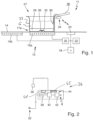
- a system 11 according to the invention is shown with an induction hob 13 according to the invention and a cooking vessel 27.
- the induction hob 13 has a hob plate 14, under which, for example, two induction heating coils 16a and 16b are arranged at some distance. In practice, this is advantageously more induction heating coils 16, for example four or six or eight or even up to twenty or thirty induction heating coils in so-called surface hobs.
- the induction hob 13 has a hob control 18, which is connected to a power supply 20, a transmitting/receiving device as the aforementioned communication device 22 for wireless communication and an operating device 24 on the underside of the hob plate 14.
- the power supply advantageously has power switches in the usual wiring.
- the operating device 24 has operating elements, preferably as touch switches, and optionally also display means such as illuminated displays and/or displays.
- a radio standard for the communication device 22 can basically be designed in a variety of ways, as explained at the beginning. Of the aforementioned options, Bluetooth or BLE is advantageous, but also ZigBee, WLAN or similar, as well as proprietary solutions without a generally applicable standard.
- a cooking area 17 is formed with an area that corresponds approximately to the area of the induction heating coils 16.
- a cooking vessel 27 according to the invention with a cooking vessel base 29 and a cooking vessel wall 33 as well as a handle 28 is arranged or placed there on the top of the cooking surface plate 14.
- a general cooking item G is located there.
- the cooking vessel 27 has an aforementioned induction coil 32 in a recess 30 of the cooking vessel base 29.
- the induction coil 32 has a few turns and is arranged on the underside of the cooking vessel base 29 in such a way that it is exposed or is not shielded from the rest of the base against the magnetic field of the induction heating coil 16a.
- the induction coil 32 is connected to the cookware module 34 as the aforementioned structural unit, which is Fig.2 is shown in an enlarged form and is explained in more detail below.
- the cookware module 34 is in wireless communication or radio connection with the communication device 22.
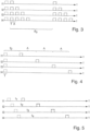
- the cookware module 34 is shown in an enlarged view.
- the cookware module 34 is connected to the induction coil 32 by means of an electrical connection as a cable or the like.
- the cookware module 34 is electrically connected to an aforementioned temperature sensor 36, which is arranged outside of it and advantageously according to Fig.1 is arranged inside the cookware 27 so that it is surrounded by water or food G located therein and can determine its temperature.
- This temperature sensor 36 can also be arranged even lower and thus closer to the cookware base 29 or even be embedded in this cookware base 29 if the temperature of the base rather than the food temperature is to be measured.
- the induction coil 32 can be provided directly in place of the induction coil 32 and connected in the same way, alternatively in addition to this in the cookware base 29.
- the temperature sensor 36 instead of the temperature sensor 36, other sensors such as pressure sensors, weight sensors or the like can be provided alternatively or in addition.
- the cookware module 34 has an energy storage device 38 that is directly connected to the induction coil 32.
- This can be an accumulator, alternatively it can be a capacitor, since it does not have to store particularly large amounts of energy, especially when sending via Bluetooth or BLE or Zigbee, but this should be as fast and loss-free as possible.
- the energy storage device 38 is present without the admittedly complex to arrange induction coil. 32.
- the energy storage device 38 can be designed for somewhat larger amounts of energy and can be a rechargeable accumulator or a battery that can be replaced.
- An integrated circuit is provided in the cookware module 34 as a cookware control 40, advantageously as a microcontroller.
- the cookware control 40 controls a communication device 42 of the cookware 27 with a transmitting antenna 44, advantageously designed for the aforementioned Bluetooth or BLE standard or Zigbee.
- the communication device 42 is in the aforementioned wireless communication or radio connection with the communication device 22.
- the cookware module 34 contains a vibration sensor 41, which is designed as described above and is advantageously based on a piezoelectric effect or MEMS technology.
- This vibration sensor 41 is designed as explained above so that it detects structure-borne noise or oscillations or vibrations, both in terms of time, i.e. in terms of duration and frequency, and also in terms of height or intensity. Vibrations that have been triggered by the inductive heating can then be detected in terms of frequency and intensity as well as duration.
- the cookware module 34 contains a holding magnet 45. This serves to attach the cookware module 34 to the handle 28 of the cookware 27, as shown in the Fig.1 is shown. This allows the cookware module 34 to be attached magnetically to the handle 28, for example on the underside close to the wall 33. This impairs the functionality of the handle 28 as little as possible.
- a magnetic attachment a locking device as mentioned above can be provided.
- attachment to the handle 28 can be made with a type of clamp or band. In any case, it is important that the cookware module 34 and thus also the vibration sensor 41 are firmly attached to the cookware 27 itself or to the handle 28 or are even integrated in the handle 28.
- the cookware module 34 including the temperature sensor 36 can be easily and advantageously removed from the cookware 27 without tools; an electrical connection to the induction coil 32 could be designed to be separable by means of a plug connection.
- FIG.3 A first example of certain predetermined temporal patterns for power generation for four induction heating coils I1 to I4 is shown.
- a dotted synchronization ping can be sent simultaneously for all four induction heating coils generated, but this does not necessarily have to be the case.
- Such a synchronization ping as well as the other pings or pulses are advantageously generated in the manner mentioned above with an operating frequency or resonance frequency of an oscillating circuit of the power supply for the induction heating coils I1 to I4, in which the respective induction heating coil is located.
- Its duration can be in the aforementioned range, for example 50 msec. This is sufficient for reliable detection by means of the vibration sensor 41 that such a ping has occurred and how long it lasted.
- the intensity or power level does not need to be very high; it can be between 1% and 20% of a maximum power of the induction heating coil.
- a first ping with a certain height or intensity is generated at all four induction heating coils I for the duration T, for example 50 msec.
- the next individual ping with the same shape is only generated again after the time interval A 0.
- a second ping with the same shape is generated shortly after the first ping, namely with the time interval A.
- a while passes, namely (Ao-TA) until a first ping is generated again at the same time as the first induction heating coil I1 and then, after a short time interval A, a second ping is generated.
- the time interval A can be 50 msec to 500 msec, for example around 100 msec.
- the time interval A 0 can be 1 sec to 4 sec. Two pings received within the time A 0 indicate the second induction heating coil I2.
- the number of the induction heating coil I generating this pattern can be read directly or recognized by the cookware control 40.
- This information is therefore recognized by the cookware control 40 and, in cooperation with the communication device 42, sent as information via the communication device 22 to the hob control 18.
- This sent information can then, for example, already be the evaluated number, i.e. "1" or "11” or similar.
- only the pattern of the coding or the pings could be sent, so that the evaluation is then largely carried out by the hob control 18.
- the vibration sensor 41 detects vibrations with a temporal pattern of the pings generated by the induction heating coil I1.
- the detected pattern corresponds relatively closely to that of the Fig.3 .
- An inductive energy transfer from one of the other induction heating coils is not detected, since their magnetic field is not transmitted or coupled into the cookware 27.
- the hob control 18 detects, based on the feedback from the cookware control 40, that this cookware 27 has received the specific predetermined time pattern of the induction heating coil I1 and must therefore be placed on it.
- the hob control 18 thus assigns this cookware 27 to this induction heating coil I1 or 16a according to Fig.1
- Temperature signals or information transmitted by the temperature sensor 36 can then be used by the hob control 18 as belonging to this induction heating coil.
- the temperature of the food being cooked in the cookware 27 can thus be controlled using the induction heating coil I1 or 16a.
- a first ping shown as a dotted line, is generated at all four induction heating coils I1 to I4 at the same time for synchronization with a duration T.
- a second ping is generated at the first induction heating coil I1.
- the second ping is generated at the second induction heating coil I2
- the second ping is generated at the third induction heating coil I3, etc.
- the time interval to can correspond to that of A, so that the number of the induction heating coil can be read by counting these time intervals until the pattern is used again. to or A can be around 200 msec to 600 msec here.
- Fig.5 an advantageous specific predetermined temporal pattern is shown for four induction heating coils I1 to I4.
- the time interval to the subsequent second ping which varies from t1 to t4, gives the number of the induction heating coil sending this pattern.
- this time interval can be a multiple of a time t 1 .
- t 2 2 ⁇ t 1
- the number of the induction heating coil can be recognized here from the multiple of the known time t 1 .
- the duration t 1 can be approximately 100 msec to 500 msec.
- the number of the induction heating coil in the cooking vessel 27 over which the cookware 27 is located or whose pattern can be received can be communicated to the external operating device 46, and possibly also to the hob control 18. This allows a reliable assignment of precisely this cookware 27 to precisely this cooking point 17 or this induction heating coil 16, which is very important. Since the cookware 27 also has other sensors such as the temperature sensor 36, a precisely running cooking program or the like can be carried out in a known manner.
- the "pings" described above are very short, very low power outputs that can only heat the cookware imperceptibly. However, the power output can also be so high that the cookware is heated slightly, preferably by a few Kelvin.
- FIG.6 A possibility is shown how, with four induction heating coils I1 to I4, a distinction can be created as a pattern after a synchronization ping is sent simultaneously for all induction heating coils with an amplitude or intensity of a subsequently sent ping.
- the intensity increases gradually with the higher number of the induction heating coil.
- the pings with different intensities are sent simultaneously here, as they can be easily distinguished.
- they can also be sent with a time delay as an additional distinction, for example similar to Fig. 3 to 5 .
- the time interval within each pattern to the subsequent synchronization ping is always to. What matters here is the intensity with which the vibration sensor 41 detects vibrations on the cookware 27 after the synchronization ping or how intense these are compared to the synchronization ping.
- Fig.7 shows a way of making a distinction based on the length of the power input in four induction heating coils I1 to I4 as a pattern.
- a synchronization ping is generated with an amplitude or intensity of a subsequently sent ping.
- this synchronization ping does not necessarily have to be generated, which is why it is shown in dotted lines.
- a ping or second ping is generated at the induction heating coil I1 for the duration A.
- a synchronization ping shown in dotted lines is generated again at all induction heating coils. The pattern then repeats regularly for the induction heating coil 11.
- a second ping is generated a time t0 after the synchronization ping shown in dotted lines, with a duration of 2xA, i.e. twice as long as at the induction heating coil 11. This pattern is also repeated.
- a second ping is generated a time t0 after the synchronization ping for a duration of 3xA or 4xA.
- this pattern is repeated continuously, as in Fig.7 is shown.
Landscapes
- Physics & Mathematics (AREA)
- Electromagnetism (AREA)
- Cookers (AREA)
Claims (15)
- Système (11) avec une table de cuisson (13) et avec une ustensile de cuisson (27), la table de cuisson (13) comprenant :- une plaque de cuisson (14),- une commande de table de cuisson (18),- un dispositif de communication (22) pour une communication sans fil avec l'ustensile de cuisson (27), le dispositif de communication (22) étant connecté à la commande de la table de cuisson (18),l'ustensile de cuisson (27) comprenant :- un capteur de vibrations (41) pour détecter les vibrations de l'ustensile de cuisson (27), qui est fixé à l'ustensile de cuisson (27),- une commande d'ustensile de cuisson (40) qui est reliée au capteur de vibrations (41) et qui est conçue pour reconnaître les signaux de capteur de celui-ci,- un dispositif de communication (42), le dispositif de communication (42) étant conçu pour une communication sans fil avec le dispositif de communication (22) de la table de cuisson et étant relié à la commande d'ustensile de cuisson (40),caractérisé en ce que- un dispositif de chauffage par induction (16) sous la plaque de cuisson (14) pour le chauffage par induction de l'ustensile de cuisson (27),- une alimentation en puissance (20) pour le dispositif de chauffage par induction (16), qui est reliée à la commande de la table de cuisson (18),- la commande de table de cuisson (18) est conçue pour commander, au moyen de l'alimentation en puissance (20), le dispositif de chauffage par induction (16) avec un modèle temporel prédéterminé déterminé en tant que production de puissance, ce modèle temporel déterminé étant caractéristique de ce dispositif de chauffage par induction (16),- la commande d'ustensile de cuisson (18) est conçue pour détecter des vibrations par l'intermédiaire du capteur de vibrations (41) ou un comportement temporel détecté de vibrations sur l'ustensile de cuisson (27), qui ont été déclenchées respectivement par le chauffage par induction de l'ustensile de cuisson (27) au moyen du dispositif de chauffage par induction (16), comme modèle, de l'identifier et d'envoyer sans fil une signalisation correspondant au modèle au moyen du dispositif de communication (42) au dispositif de communication (22) de la table de cuisson (13),- le contrôleur de table de cuisson (18) est conçu pour comparer, sur la base de la signalisation provenant de la commande d'ustensile de cuisson (40), une comparaison avec le modèle de génération de puissance pour un dispositif de chauffage par induction (16) donné,- le contrôleur de table de cuisson (18) est adapté pour définir l'ustensile de cuisson (27) comme étant chauffé par le dispositif de chauffage par induction (16) et donc associé à celui-ci, dans le cas où la signalisation reçue de la commande d'ustensile de cuisson (40) est adaptée et/ou correspond au modèle de génération de puissance du dispositif de chauffage par induction (16).
- Système selon la revendication 1, caractérisé en ce que l'ustensile de cuisson (27) comporte un capteur de température (36) configuré pour détecter une température au fond de l'ustensile de cuisson (29) ou dans l'ustensile de cuisson (27), le capteur de température (36) étant relié à la commande de l'ustensile de cuisson (40), notamment par un câble de raccordement.
- Système selon la revendication 2, caractérisé en ce que le capteur de température (36) peut être fixé de manière amovible sans outil à l'ustensile de cuisson (27), de préférence au moyen d'un dispositif d'encliquetage ou au moyen de la force magnétique, en particulier près du fond de l'ustensile de cuisson (29), de préférence à l'intérieur de l'ustensile de cuisson (27).
- Système selon l'une des revendications précédentes, caractérisé en ce que le capteur de vibrations (41) n'est pas disposé à l'intérieur du récipient de l'ustensile de cuisson, en particulier il est disposé sur une face extérieure de la paroi de l'ustensile de cuisson ou sur un dispositif de préhension (28) de l'ustensile de cuisson (27).
- Système selon la revendication 4, caractérisé en ce que le capteur de vibrations (41) peut être fixé de manière amovible sans outil à l'ustensile de cuisson (27), de préférence au moyen d'un dispositif d'encliquetage ou d'une force magnétique (45).
- Système selon l'une des revendications précédentes, caractérisé en ce que le capteur de vibrations (41) est un capteur intégré sous la forme d'un module de capteur, le capteur de vibrations (41) étant de préférence conçu pour détecter des vibrations mécaniques et/ou des bruits de structure et n'étant pas conçu pour détecter des modifications acoustiques et/ou optiques.
- Système selon l'une des revendications précédentes, caractérisé en ce que la commande d'ustensile de cuisson (40), le dispositif de communication (42) et le capteur de vibrations (41) sont disposés dans une unité modulaire (34) ou sont disposés dans un boîtier sur l'ustensile de cuisson (27), en particulier sur un dispositif de poignée (28) de l'ustensile de cuisson (27).
- Système selon la revendication 7, caractérisé en ce que l'unité modulaire (34) peut être fixée de manière amovible sans outil à l'ustensile de cuisson (27), de préférence au moyen d'un dispositif d'encliquetage ou d'une force magnétique (45).
- Système selon l'une des revendications précédentes, caractérisé en ce que l'ustensile de cuisson (27) ou la commande d'ustensile de cuisson (40) comporte sa propre source d'énergie (38), de préférence une batterie.
- Système selon l'une quelconque des revendications 1 à 8, caractérisé en ce que la commande d'ustensile de cuisson (40) comprend un générateur d'induction avec sa propre bobine d'induction (32) pour l'alimentation en énergie, la bobine d'induction (32) étant de préférence disposée dans la zone inférieure de l'ustensile de cuisson (27), de préférence au fond de l'ustensile de cuisson (29).
- Procédé de fonctionnement d'un système selon l'une des revendications précédentes, caractérisé en ce que les étapes suivantes sont effectuées :- Mise en marche de la table de cuisson (13),- Mise en place d'un ustensile de cuisson (27) sur la plaque de cuisson (14) au-dessus du dispositif de chauffage par induction (16),- Détection de la pose de l'ustensile de cuisson (27) sur le dispositif de chauffage par induction (16) par la commande de la table de cuisson (18),- Fonctionnement du dispositif de chauffage par induction (16) selon un modèle prédéfini déterminé pour la production de puissance avec une variation dans le temps et, le cas échéant, avec une variation supplémentaire de la hauteur de la production de puissance,- Détection de vibrations sur l'ustensile de cuisson (27) au moyen du capteur de vibrations (41), qui sont déclenchées par la transmission de puissance par induction au fond (29) de l'ustensile de cuisson (27),- Reconnaissance du modèle de génération de puissance par la commande d'ustensile de cuisson (40) sur la base des vibrations détectées sur l'ustensile de cuisson (27),- Envoyer des informations sur le modèle de production d'énergie par la commande d'ustensile de cuisson (40) au moyen du dispositif de communication (42) de l'ustensile de cuisson (27) au dispositif de communication (22) de la table de cuisson (13),- l'association des informations transmises par l'ustensile de cuisson (27) au dispositif de chauffage par induction (16) par le contrôleur de table de cuisson (18) et l'association de l'ustensile de cuisson (27) reconnu à ce dispositif de chauffage par induction (16),- chauffage par induction de l'ustensile de cuisson (27) au moyen du dispositif de chauffage par induction (16) associé.
- Procédé selon la revendication 11, caractérisé en ce qu'en plus de l'affectation de l'ustensile de cuisson (27) au dispositif de chauffage par induction (16) sur la base de la signalisation à l'aide du capteur de vibrations (41), un chauffage effectif de l'ustensile de cuisson (27) par le dispositif de chauffage par induction (16) est contrôlé après un temps de contrôle prédéfini déterminé à l'aide d'une augmentation de température au niveau du capteur de température (36), de préférence, dans le cas où l'augmentation de température n'est pas détectée au niveau du capteur de température (36), le processus de détection de l'association du dispositif de chauffage par induction (16) à l'ustensile de cuisson (27) est redémarré.
- Procédé selon la revendication 11 ou 12, caractérisé en ce qu'un mouvement vertical et/ou un mouvement latéral de l'ustensile de cuisson (27) est détecté au moyen du capteur de vibrations (41) et une signalisation correspondante est transmise par la commande de l'ustensile de cuisson (40) à la commande de la table de cuisson (18) via les dispositifs de communication (22, 42), l'éloignement de l'ustensile de cuisson (27) du dispositif de chauffage par induction (16) étant détecté par la commande de table de cuisson (18) conjointement avec l'alimentation en puissance (20) et un fonctionnement du dispositif de chauffage par induction (16) en tant que capteur de détection de casserole inductif, et une production de puissance étant ensuite interrompue sur le dispositif de chauffage par induction (16), dans lequel, notamment après détection d'un nouveau mouvement vertical de l'ustensile de cuisson (27) avec arrêt soudain du mouvement, la pose de l'ustensile de cuisson (27) sur une surface (14) est détectée et une signalisation correspondante est transmise par le dispositif de commande d'ustensile de cuisson (18) au dispositif de commande de table de cuisson (18) par l'intermédiaire des dispositifs de communication (22, 42), et le dispositif de commande de table de cuisson (18) exécute alors directement un procédé de détection de casserole sur tous les dispositifs de chauffage par induction (16) qui ne sont pas recouverts par un ustensile de cuisson (27).
- Procédé selon l'une des revendications 11 à 13, caractérisé en ce que le capteur de température (36) de l'ustensile de cuisson (27) est relié a la commande d'ustensile de cuisson (40) pour lire des signaux de température, la commande d'ustensile de cuisson (40) transmettant l'information de température à l'aide des signaux de température via le dispositif de communication (42) au dispositif de communication (22) de la table de cuisson (13) pour une utilisation dans le contrôleur de table de cuisson (18).
- Procédé selon l'une quelconque des revendications 11 à 14, caractérisé en ce que, après avoir détecté la mise en place de l'ustensile de cuisson (27) par l'intermédiaire d'un dispositif de chauffage par induction (16), le contrôleur de table de cuisson (18) commande, au moyen de l'alimentation électrique (20), ce dispositif de chauffage par induction (16) de manière à ce qu'il fonctionne avec un modèle de différentes fréquences de travail et/ou de différents niveaux de puissance afin de générer des vibrations dans l'ustensile de cuisson (27) placé au-dessus, ce qui entraîne différentes vibrations harmoniques dans l'ustensile de cuisson (27), qui sont caractéristiques de cet ustensile de cuisson (27), ces vibrations étant détectées au moyen du capteur de vibrations (41) et des informations à ce sujet étant transmises par la commande de l'ustensile de cuisson (40) au moyen des dispositifs de communication (22, 42) à la commande de la table de cuisson (18) pour l'identification de l'ustensile de cuisson (27), certaines données et/ou propriétés concernant cet ustensile de cuisson (27) étant de préférence mémorisées dans la commande de l'ustensile de cuisson (40) ou dans la commande de la table de cuisson (18).
Applications Claiming Priority (1)
| Application Number | Priority Date | Filing Date | Title |
|---|---|---|---|
| DE102020201005.6A DE102020201005A1 (de) | 2020-01-28 | 2020-01-28 | System mit einem Kochfeld und einem Kochgeschirr und Verfahren zum Betrieb des Systems |
Publications (2)
| Publication Number | Publication Date |
|---|---|
| EP3860307A1 EP3860307A1 (fr) | 2021-08-04 |
| EP3860307B1 true EP3860307B1 (fr) | 2024-07-17 |
Family
ID=74194570
Family Applications (1)
| Application Number | Title | Priority Date | Filing Date |
|---|---|---|---|
| EP21152548.0A Active EP3860307B1 (fr) | 2020-01-28 | 2021-01-20 | Système doté d'une plaque de cuisson et d'un ustensile de cuisson et procédé de fonctionnement dudit système |
Country Status (4)
| Country | Link |
|---|---|
| EP (1) | EP3860307B1 (fr) |
| DE (1) | DE102020201005A1 (fr) |
| ES (1) | ES2991431T3 (fr) |
| PL (1) | PL3860307T3 (fr) |
Families Citing this family (3)
| Publication number | Priority date | Publication date | Assignee | Title |
|---|---|---|---|---|
| AT17633U1 (de) | 2020-04-23 | 2022-09-15 | Pke Holding Ag | Computerimplementiertes Verfahren zur Bestimmung einer Flächenbelegung einer Lagerfläche |
| DE102020212169B3 (de) | 2020-09-28 | 2022-02-10 | E.G.O. Elektro-Gerätebau GmbH | Verfahren zur Bestimmung einer Topfposition eines Topfes auf einem Kochfeld und Kochfeld |
| DE112022004311A5 (de) * | 2021-09-08 | 2024-08-08 | BSH Hausgeräte GmbH | Gargeschirrsensorvorrichtung |
Family Cites Families (10)
| Publication number | Priority date | Publication date | Assignee | Title |
|---|---|---|---|---|
| DE102004016631A1 (de) | 2004-03-29 | 2005-11-10 | E.G.O. Elektro-Gerätebau GmbH | Vorrichtung und Verfahren zur Überwachung der Temperatur eines Kochgeschirrs auf einer Abdeckung eines Kochfeldes sowie von weiteren Vorgängen auf der Abdeckung |
| DE102009047185B4 (de) | 2009-11-26 | 2012-10-31 | E.G.O. Elektro-Gerätebau GmbH | Verfahren und Induktionsheizeinrichtung zum Ermitteln einer Temperatur eines mittels einer Induktionsheizspule erwärmten Kochgefäßbodens |
| ES2687697T3 (es) * | 2012-10-11 | 2018-10-26 | Arçelik Anonim Sirketi | Un dispositivo de cocina inalámbrico operado sobre un fogón de calentamiento por inducción |
| ES2948067T3 (es) | 2013-07-09 | 2023-08-30 | Bsh Hausgeraete Gmbh | Campo de cocción |
| ES2627629T3 (es) | 2014-09-29 | 2017-07-28 | E.G.O. Elektro-Gerätebau GmbH | Método para detectar la identidad de una olla sobre un punto de cocción de una encimera de cocción y sistema de una encimera de cocción con una olla |
| DE102015222797A1 (de) | 2015-11-18 | 2017-05-18 | BSH Hausgeräte GmbH | System mit Kochgerät und Kochgeschirr |
| ES2975178T3 (es) | 2015-12-02 | 2024-07-03 | Ego Elektro Geraetebau Gmbh | Método de funcionamiento de una encimera de cocción por inducción |
| DE102016108680A1 (de) | 2016-05-11 | 2017-11-16 | Miele & Cie. Kg | Kochsystem mit Kochstelle und Kochgeschirr |
| DE102018119969A1 (de) * | 2018-08-16 | 2020-02-20 | Miele & Cie. Kg | Verfahren zur automatischen Zuordnung mindestens eines Aufstellgeräts zu mindestens einer Kochstelle eines induktiven Kochfelds und System zur Durchführung des Verfahrens |
| DE102018221521A1 (de) | 2018-12-12 | 2020-06-18 | E.G.O. Elektro-Gerätebau GmbH | Verfahren zum Betrieb eines Induktionskochfelds |
-
2020
- 2020-01-28 DE DE102020201005.6A patent/DE102020201005A1/de not_active Withdrawn
-
2021
- 2021-01-20 ES ES21152548T patent/ES2991431T3/es active Active
- 2021-01-20 PL PL21152548.0T patent/PL3860307T3/pl unknown
- 2021-01-20 EP EP21152548.0A patent/EP3860307B1/fr active Active
Also Published As
| Publication number | Publication date |
|---|---|
| PL3860307T3 (pl) | 2025-02-03 |
| ES2991431T3 (es) | 2024-12-03 |
| DE102020201005A1 (de) | 2021-07-29 |
| EP3860307A1 (fr) | 2021-08-04 |
Similar Documents
| Publication | Publication Date | Title |
|---|---|---|
| EP3860307B1 (fr) | Système doté d'une plaque de cuisson et d'un ustensile de cuisson et procédé de fonctionnement dudit système | |
| EP3675597B1 (fr) | Procédé de fonctionnement d'un système de cuisson inductif | |
| EP3244694B1 (fr) | Système de cuisson comprenant un ustensile de cuisson et plaque de cuisson | |
| EP3668274A1 (fr) | Méthode de contrôle d'une plaque à induction | |
| EP3893603B1 (fr) | Système de cuisine à induction | |
| EP3614796B1 (fr) | Procédé d'attribution automatique d'au moins un appareil de montage d'au moins un point de cuisson d'une plaque de cuisson inductive, plaque de cuisson inductive, dispositif de montage et système de mise en uvre dudit procédé | |
| EP3890438B1 (fr) | Procédé de chauffage d'un récipient de cuisson sur une plaque de cuisson et plaque de cuisson | |
| DE102009029253A1 (de) | Verfahren zum Zuordnen eines Aufsatzgeräts zu einer Basisstation eines Betriebsgeräts und Betriebsgerät | |
| EP3813486B1 (fr) | Procédé de fonctionnement d'un système de cuisson ainsi que plaque de cuisson et récipient de cuisson | |
| EP0780081A1 (fr) | Méthode pour régler automatiquement des emplacements de cuisson chauffants | |
| EP3079444A1 (fr) | Procede de fonctionnement d'un champ de cuisson et champ de cuisson | |
| EP3282816B1 (fr) | Système de cuisson à induction | |
| DE102019132478A1 (de) | Verfahren zur automatischen Zuordnung mindestens eines Tauchsiedergeräts zu mindestens einer Kochstelle eines induktiven Kochfelds, induktives Kochfeld, Tauchsiedergerät und System zur Durchführung des Verfahrens | |
| EP4114141B1 (fr) | Procédé permettant de faire fonctionner une plaque de cuisson à induction et plaque de cuisson à induction | |
| EP3383133B1 (fr) | Système de cuisson et procédé d'un fonctionnement d'un système de cuisson | |
| BE1031250B1 (de) | Gargeschirr zum Abstellen auf einem Induktionskochfeld eines Garsystems zum Garen von Gargut, Garsystem zum Garen von Gargut und Verfahren zum Betreiben eines Garsystems | |
| WO2023036612A1 (fr) | Appareil de détection d'ustensile de cuisine | |
| DE102023200827B3 (de) | Verfahren zum Betreiben eines Kochfelds, Verfahren zum Betreiben einer Garvorrichtung, Kochfeld und Garvorrichtung | |
| EP4312465A1 (fr) | Procédé de fonctionnement d'un système de cuisson ainsi que plaque de cuisson et vaisselle de cuisson | |
| EP4454413A1 (fr) | Dispositif de capteur, article de placement, système de plaque de cuisson et procédé de fonctionnement d'un dispositif de capteur | |
| EP4390231A1 (fr) | Procédé de fonctionnement d'un système de commande ainsi que dispositif de fonctionnement et dispositif de commande mobile | |
| DE102020115675A1 (de) | Verfahren zum Betrieb eines induktiven Systems, vorzugweise eines induktiven Kochsystems | |
| EP3780907A1 (fr) | Système, comprenant une plaque de cuisson inductive et un utensile de cuisson, utensile de cuisson et procédé de fonctionnement du système |
Legal Events
| Date | Code | Title | Description |
|---|---|---|---|
| PUAI | Public reference made under article 153(3) epc to a published international application that has entered the european phase |
Free format text: ORIGINAL CODE: 0009012 |
|
| STAA | Information on the status of an ep patent application or granted ep patent |
Free format text: STATUS: THE APPLICATION HAS BEEN PUBLISHED |
|
| AK | Designated contracting states |
Kind code of ref document: A1 Designated state(s): AL AT BE BG CH CY CZ DE DK EE ES FI FR GB GR HR HU IE IS IT LI LT LU LV MC MK MT NL NO PL PT RO RS SE SI SK SM TR |
|
| STAA | Information on the status of an ep patent application or granted ep patent |
Free format text: STATUS: REQUEST FOR EXAMINATION WAS MADE |
|
| 17P | Request for examination filed |
Effective date: 20220204 |
|
| RBV | Designated contracting states (corrected) |
Designated state(s): AL AT BE BG CH CY CZ DE DK EE ES FI FR GB GR HR HU IE IS IT LI LT LU LV MC MK MT NL NO PL PT RO RS SE SI SK SM TR |
|
| GRAP | Despatch of communication of intention to grant a patent |
Free format text: ORIGINAL CODE: EPIDOSNIGR1 |
|
| STAA | Information on the status of an ep patent application or granted ep patent |
Free format text: STATUS: GRANT OF PATENT IS INTENDED |
|
| INTG | Intention to grant announced |
Effective date: 20240429 |
|
| GRAS | Grant fee paid |
Free format text: ORIGINAL CODE: EPIDOSNIGR3 |
|
| GRAA | (expected) grant |
Free format text: ORIGINAL CODE: 0009210 |
|
| STAA | Information on the status of an ep patent application or granted ep patent |
Free format text: STATUS: THE PATENT HAS BEEN GRANTED |
|
| AK | Designated contracting states |
Kind code of ref document: B1 Designated state(s): AL AT BE BG CH CY CZ DE DK EE ES FI FR GB GR HR HU IE IS IT LI LT LU LV MC MK MT NL NO PL PT RO RS SE SI SK SM TR |
|
| REG | Reference to a national code |
Ref country code: CH Ref legal event code: EP |
|
| REG | Reference to a national code |
Ref country code: DE Ref legal event code: R096 Ref document number: 502021004360 Country of ref document: DE |
|
| REG | Reference to a national code |
Ref country code: IE Ref legal event code: FG4D Free format text: LANGUAGE OF EP DOCUMENT: GERMAN |
|
| REG | Reference to a national code |
Ref country code: LT Ref legal event code: MG9D |
|
| REG | Reference to a national code |
Ref country code: NL Ref legal event code: MP Effective date: 20240717 |
|
| REG | Reference to a national code |
Ref country code: ES Ref legal event code: FG2A Ref document number: 2991431 Country of ref document: ES Kind code of ref document: T3 Effective date: 20241203 |
|
| PG25 | Lapsed in a contracting state [announced via postgrant information from national office to epo] |
Ref country code: PT Free format text: LAPSE BECAUSE OF FAILURE TO SUBMIT A TRANSLATION OF THE DESCRIPTION OR TO PAY THE FEE WITHIN THE PRESCRIBED TIME-LIMIT Effective date: 20241118 |
|
| PG25 | Lapsed in a contracting state [announced via postgrant information from national office to epo] |
Ref country code: NL Free format text: LAPSE BECAUSE OF FAILURE TO SUBMIT A TRANSLATION OF THE DESCRIPTION OR TO PAY THE FEE WITHIN THE PRESCRIBED TIME-LIMIT Effective date: 20240717 |
|
| PG25 | Lapsed in a contracting state [announced via postgrant information from national office to epo] |
Ref country code: PT Free format text: LAPSE BECAUSE OF FAILURE TO SUBMIT A TRANSLATION OF THE DESCRIPTION OR TO PAY THE FEE WITHIN THE PRESCRIBED TIME-LIMIT Effective date: 20241118 Ref country code: NL Free format text: LAPSE BECAUSE OF FAILURE TO SUBMIT A TRANSLATION OF THE DESCRIPTION OR TO PAY THE FEE WITHIN THE PRESCRIBED TIME-LIMIT Effective date: 20240717 |
|
| PG25 | Lapsed in a contracting state [announced via postgrant information from national office to epo] |
Ref country code: NO Free format text: LAPSE BECAUSE OF FAILURE TO SUBMIT A TRANSLATION OF THE DESCRIPTION OR TO PAY THE FEE WITHIN THE PRESCRIBED TIME-LIMIT Effective date: 20241017 |
|
| PG25 | Lapsed in a contracting state [announced via postgrant information from national office to epo] |
Ref country code: GR Free format text: LAPSE BECAUSE OF FAILURE TO SUBMIT A TRANSLATION OF THE DESCRIPTION OR TO PAY THE FEE WITHIN THE PRESCRIBED TIME-LIMIT Effective date: 20241018 Ref country code: FI Free format text: LAPSE BECAUSE OF FAILURE TO SUBMIT A TRANSLATION OF THE DESCRIPTION OR TO PAY THE FEE WITHIN THE PRESCRIBED TIME-LIMIT Effective date: 20240717 |
|
| PG25 | Lapsed in a contracting state [announced via postgrant information from national office to epo] |
Ref country code: BG Free format text: LAPSE BECAUSE OF FAILURE TO SUBMIT A TRANSLATION OF THE DESCRIPTION OR TO PAY THE FEE WITHIN THE PRESCRIBED TIME-LIMIT Effective date: 20240717 |
|
| PG25 | Lapsed in a contracting state [announced via postgrant information from national office to epo] |
Ref country code: LV Free format text: LAPSE BECAUSE OF FAILURE TO SUBMIT A TRANSLATION OF THE DESCRIPTION OR TO PAY THE FEE WITHIN THE PRESCRIBED TIME-LIMIT Effective date: 20240717 |
|
| PG25 | Lapsed in a contracting state [announced via postgrant information from national office to epo] |
Ref country code: IS Free format text: LAPSE BECAUSE OF FAILURE TO SUBMIT A TRANSLATION OF THE DESCRIPTION OR TO PAY THE FEE WITHIN THE PRESCRIBED TIME-LIMIT Effective date: 20241117 |
|
| PG25 | Lapsed in a contracting state [announced via postgrant information from national office to epo] |
Ref country code: HR Free format text: LAPSE BECAUSE OF FAILURE TO SUBMIT A TRANSLATION OF THE DESCRIPTION OR TO PAY THE FEE WITHIN THE PRESCRIBED TIME-LIMIT Effective date: 20240717 |
|
| PG25 | Lapsed in a contracting state [announced via postgrant information from national office to epo] |
Ref country code: RS Free format text: LAPSE BECAUSE OF FAILURE TO SUBMIT A TRANSLATION OF THE DESCRIPTION OR TO PAY THE FEE WITHIN THE PRESCRIBED TIME-LIMIT Effective date: 20241017 |
|
| PG25 | Lapsed in a contracting state [announced via postgrant information from national office to epo] |
Ref country code: RS Free format text: LAPSE BECAUSE OF FAILURE TO SUBMIT A TRANSLATION OF THE DESCRIPTION OR TO PAY THE FEE WITHIN THE PRESCRIBED TIME-LIMIT Effective date: 20241017 Ref country code: NO Free format text: LAPSE BECAUSE OF FAILURE TO SUBMIT A TRANSLATION OF THE DESCRIPTION OR TO PAY THE FEE WITHIN THE PRESCRIBED TIME-LIMIT Effective date: 20241017 Ref country code: LV Free format text: LAPSE BECAUSE OF FAILURE TO SUBMIT A TRANSLATION OF THE DESCRIPTION OR TO PAY THE FEE WITHIN THE PRESCRIBED TIME-LIMIT Effective date: 20240717 Ref country code: IS Free format text: LAPSE BECAUSE OF FAILURE TO SUBMIT A TRANSLATION OF THE DESCRIPTION OR TO PAY THE FEE WITHIN THE PRESCRIBED TIME-LIMIT Effective date: 20241117 Ref country code: HR Free format text: LAPSE BECAUSE OF FAILURE TO SUBMIT A TRANSLATION OF THE DESCRIPTION OR TO PAY THE FEE WITHIN THE PRESCRIBED TIME-LIMIT Effective date: 20240717 Ref country code: GR Free format text: LAPSE BECAUSE OF FAILURE TO SUBMIT A TRANSLATION OF THE DESCRIPTION OR TO PAY THE FEE WITHIN THE PRESCRIBED TIME-LIMIT Effective date: 20241018 Ref country code: FI Free format text: LAPSE BECAUSE OF FAILURE TO SUBMIT A TRANSLATION OF THE DESCRIPTION OR TO PAY THE FEE WITHIN THE PRESCRIBED TIME-LIMIT Effective date: 20240717 Ref country code: BG Free format text: LAPSE BECAUSE OF FAILURE TO SUBMIT A TRANSLATION OF THE DESCRIPTION OR TO PAY THE FEE WITHIN THE PRESCRIBED TIME-LIMIT Effective date: 20240717 |
|
| PG25 | Lapsed in a contracting state [announced via postgrant information from national office to epo] |
Ref country code: DK Free format text: LAPSE BECAUSE OF FAILURE TO SUBMIT A TRANSLATION OF THE DESCRIPTION OR TO PAY THE FEE WITHIN THE PRESCRIBED TIME-LIMIT Effective date: 20240717 Ref country code: SM Free format text: LAPSE BECAUSE OF FAILURE TO SUBMIT A TRANSLATION OF THE DESCRIPTION OR TO PAY THE FEE WITHIN THE PRESCRIBED TIME-LIMIT Effective date: 20240717 Ref country code: RO Free format text: LAPSE BECAUSE OF FAILURE TO SUBMIT A TRANSLATION OF THE DESCRIPTION OR TO PAY THE FEE WITHIN THE PRESCRIBED TIME-LIMIT Effective date: 20240717 |
|
| REG | Reference to a national code |
Ref country code: DE Ref legal event code: R097 Ref document number: 502021004360 Country of ref document: DE |
|
| PG25 | Lapsed in a contracting state [announced via postgrant information from national office to epo] |
Ref country code: EE Free format text: LAPSE BECAUSE OF FAILURE TO SUBMIT A TRANSLATION OF THE DESCRIPTION OR TO PAY THE FEE WITHIN THE PRESCRIBED TIME-LIMIT Effective date: 20240717 |
|
| PGFP | Annual fee paid to national office [announced via postgrant information from national office to epo] |
Ref country code: AT Payment date: 20250417 Year of fee payment: 5 |
|
| PG25 | Lapsed in a contracting state [announced via postgrant information from national office to epo] |
Ref country code: CZ Free format text: LAPSE BECAUSE OF FAILURE TO SUBMIT A TRANSLATION OF THE DESCRIPTION OR TO PAY THE FEE WITHIN THE PRESCRIBED TIME-LIMIT Effective date: 20240717 |
|
| PG25 | Lapsed in a contracting state [announced via postgrant information from national office to epo] |
Ref country code: SK Free format text: LAPSE BECAUSE OF FAILURE TO SUBMIT A TRANSLATION OF THE DESCRIPTION OR TO PAY THE FEE WITHIN THE PRESCRIBED TIME-LIMIT Effective date: 20240717 |
|
| PLBE | No opposition filed within time limit |
Free format text: ORIGINAL CODE: 0009261 |
|
| STAA | Information on the status of an ep patent application or granted ep patent |
Free format text: STATUS: NO OPPOSITION FILED WITHIN TIME LIMIT |
|
| 26N | No opposition filed |
Effective date: 20250422 |
|
| REG | Reference to a national code |
Ref country code: CH Ref legal event code: PL |
|
| PG25 | Lapsed in a contracting state [announced via postgrant information from national office to epo] |
Ref country code: SE Free format text: LAPSE BECAUSE OF FAILURE TO SUBMIT A TRANSLATION OF THE DESCRIPTION OR TO PAY THE FEE WITHIN THE PRESCRIBED TIME-LIMIT Effective date: 20240717 |
|
| PG25 | Lapsed in a contracting state [announced via postgrant information from national office to epo] |
Ref country code: LU Free format text: LAPSE BECAUSE OF NON-PAYMENT OF DUE FEES Effective date: 20250120 Ref country code: MC Free format text: LAPSE BECAUSE OF FAILURE TO SUBMIT A TRANSLATION OF THE DESCRIPTION OR TO PAY THE FEE WITHIN THE PRESCRIBED TIME-LIMIT Effective date: 20240717 |
|
| GBPC | Gb: european patent ceased through non-payment of renewal fee |
Effective date: 20250120 |
|
| PG25 | Lapsed in a contracting state [announced via postgrant information from national office to epo] |
Ref country code: BE Free format text: LAPSE BECAUSE OF NON-PAYMENT OF DUE FEES Effective date: 20250131 Ref country code: GB Free format text: LAPSE BECAUSE OF NON-PAYMENT OF DUE FEES Effective date: 20250120 |
|
| PG25 | Lapsed in a contracting state [announced via postgrant information from national office to epo] |
Ref country code: CH Free format text: LAPSE BECAUSE OF NON-PAYMENT OF DUE FEES Effective date: 20250131 |
|
| REG | Reference to a national code |
Ref country code: BE Ref legal event code: MM Effective date: 20250131 |
|
| PG25 | Lapsed in a contracting state [announced via postgrant information from national office to epo] |
Ref country code: IT Free format text: LAPSE BECAUSE OF NON-PAYMENT OF DUE FEES Effective date: 20250120 |
|
| PG25 | Lapsed in a contracting state [announced via postgrant information from national office to epo] |
Ref country code: IE Free format text: LAPSE BECAUSE OF NON-PAYMENT OF DUE FEES Effective date: 20250120 |
|
| PGFP | Annual fee paid to national office [announced via postgrant information from national office to epo] |
Ref country code: PL Payment date: 20251222 Year of fee payment: 6 |
|
| PGFP | Annual fee paid to national office [announced via postgrant information from national office to epo] |
Ref country code: ES Payment date: 20260217 Year of fee payment: 6 |
|
| PGFP | Annual fee paid to national office [announced via postgrant information from national office to epo] |
Ref country code: DE Payment date: 20260127 Year of fee payment: 6 |
|
| PG25 | Lapsed in a contracting state [announced via postgrant information from national office to epo] |
Ref country code: IT Free format text: LAPSE BECAUSE OF NON-PAYMENT OF DUE FEES Effective date: 20250120 |
|
| PGFP | Annual fee paid to national office [announced via postgrant information from national office to epo] |
Ref country code: IT Payment date: 20260130 Year of fee payment: 6 |
|
| PGRI | Patent reinstated in contracting state [announced from national office to epo] |
Ref country code: IT Effective date: 20250603 |
|
| PGFP | Annual fee paid to national office [announced via postgrant information from national office to epo] |
Ref country code: FR Payment date: 20260127 Year of fee payment: 6 |