EP3860389B1 - Gehäuse für kopfhörer - Google Patents
Gehäuse für kopfhörer Download PDFInfo
- Publication number
- EP3860389B1 EP3860389B1 EP19801401.1A EP19801401A EP3860389B1 EP 3860389 B1 EP3860389 B1 EP 3860389B1 EP 19801401 A EP19801401 A EP 19801401A EP 3860389 B1 EP3860389 B1 EP 3860389B1
- Authority
- EP
- European Patent Office
- Prior art keywords
- flap portion
- headphones
- shell portion
- storage structure
- case
- Prior art date
- Legal status (The legal status is an assumption and is not a legal conclusion. Google has not performed a legal analysis and makes no representation as to the accuracy of the status listed.)
- Active
Links
Images




Classifications
-
- H—ELECTRICITY
- H04—ELECTRIC COMMUNICATION TECHNIQUE
- H04R—LOUDSPEAKERS, MICROPHONES, GRAMOPHONE PICK-UPS OR LIKE ACOUSTIC ELECTROMECHANICAL TRANSDUCERS; ELECTRIC HEARING AIDS; PUBLIC ADDRESS SYSTEMS
- H04R1/00—Details of transducers, loudspeakers or microphones
- H04R1/10—Earpieces; Attachments therefor ; Earphones; Monophonic headphones
- H04R1/1033—Cables or cables storage, e.g. cable reels
-
- A—HUMAN NECESSITIES
- A45—HAND OR TRAVELLING ARTICLES
- A45C—PURSES; LUGGAGE; HAND CARRIED BAGS
- A45C11/00—Receptacles for purposes not provided for in groups A45C1/00-A45C9/00
-
- A—HUMAN NECESSITIES
- A45—HAND OR TRAVELLING ARTICLES
- A45C—PURSES; LUGGAGE; HAND CARRIED BAGS
- A45C11/00—Receptacles for purposes not provided for in groups A45C1/00-A45C9/00
- A45C11/001—Receptacles for purposes not provided for in groups A45C1/00-A45C9/00 for storing portable audio devices, e.g. headphones or digital music players
Definitions
- the invention relates generally to a system comprising a headphone case, that is a case for storing headphones, in particular an in-ear headphone case, that is a case for storing in-ear headphones, and said one or more headphones.
- typical storage cases for headphones include two complementary portions that can be zipped together to close the case.
- the two complementary portions are typically hard shelled, that is to say that they do not tend to be resilient.
- Other storage cases include a plastic frame and a clip on cover for securing the headphones therein.
- US 2013/0206612 A1 describes a multi-functional accessory that acts as a case for transporting an earphone and as a stand for holding a smart cellphone or MP3 player with a display in a landscape or portrait orientation.
- An earphone holding structure is attached to the lower case and fits into the space between the upper case and the lower case when closed.
- the earphone holding structure is provided with a flange for cord wrapping when earphones are stored.
- GB 281,515 discusses a stand or holder for cigarettes.
- the stand is constructed so that, when opened, by partially rotating its lid or cover, its contents are fully displayed.
- a lid or cover is provided which remains closed by its own weight, preventing the entry of dust or dirt.
- the headphone case includes a shell portion, comprising a housing, casing or frame portion, that defines a storage space within the shell portion that is capable of storing headphones therein.
- the flap portion serves to enclose the space, or otherwise close off the enclosed space from the user.
- the flap portion and the shell portion may be configured to completely enclose the storage space when the case is in the closed configuration. In this arrangement, the ingress of dirt and debris into the storage space is mitigated.
- the flap portion and the shell portion are connected by a separate pivoting member.
- the flap portion and the shell portion are connected by a distinct pivoting member.
- the flap portion and the shell portion are connected by a distinct, separate pivoting member.
- the pivoting member allows for rotation of the flap portion about a pivot point, with respect to the shell portion. In this way, the user can rotate/pivot the flap portion with respect to the shell portion to reveal or close off the enclosed space of the shell portion. In this way, the flap portion acts as a door to allow the user to open or close the headphone case.
- this configuration, and in particular the provision of the pivoting member allows for a simple closure action by the user, and in particular enables embodiments where this can be performed without the use of both hands to open or close the case.
- the flap portion may comprise one or more planar wall portions.
- the shell portion may comprise one or more planar wall portions.
- the planar wall portions of the flap portion and/or the shell portion may include one or more curved edge portions.
- the flap portion includes a first planar wall portion
- the shell portion includes a second planar wall portion
- the flap portion is connected to the shell portion by the pivoting member such that in the closed configuration the respective planar wall portions lie substantially parallel and spaced apart either side of the storage space such as to at least in part enclose the storage space.
- the shell portion and the flap portion may comprise mutually opposable wall portions that are located either side of the storage space in the closed configuration.
- the shell portion and the flap portion may define mutually opposable walls that are located either side of the storage space in the closed configuration.
- first and second planar wall portions may sit substantially parallel in the closed configuration.
- the first and second planar wall portions may define a more open structure with the first and second planar wall portions being divergent and the storage space being accessible in the open configuration.
- One or more of the wall portions of the shell portion and one or more of the wall portions of the flap portion may include end portions configured to define a curved surface about the pivoting member.
- one or both of the first and second planar wall portions may include end portions configured to define a continuously curved surface about the pivoting member.
- One or more of the planar wall portions of the shell portion and one or more of the planar wall portions of the flap portion may be configured to define a generally elongate U-shaped structure.
- the first and second planar wall portions and the end portion(s) may define a generally elongate U-shaped structure with the first and second planar wall portions substantially parallel in the closed configuration.
- the first planar wall portion thus serves as a back wall of the case and the second planar wall portion thus serves as a front wall of the case when the shell portion and the flap portion are in the closed configuration.
- the shell portion may comprise one or more sidewalls.
- the shell portion may further include a pair of side walls and a top wall all connected to and extending from the back wall, wherein the side walls, the top wall and the back wall including any end portion thereof define the space for storing headphones, and wherein the front wall including any end portion thereof completes enclosure of the same in the closed configuration in use.
- the shell portion may further include one or more side walls and a top wall, each connected to and extending from the back wall, wherein the side walls, the top wall and the back wall, including any end portion thereof, define the space for storing headphones, and wherein the front wall, including any end portion thereof, completes enclosure of the space for storing headphones, in the closed configuration.
- the shell portion may include a first side wall and a second side wall that are connected by a back wall and a top wall.
- the first side wall, second side wall, back wall and top wall define the space in which headphones can be stored.
- the storage space contains a storage structure configured to store headphones in use, wherein the storage structure is not accessible in the closed configuration and wherein the storage structure is accessible in the open configuration.
- the storage space defined within the shell portion is configured to enable the storage structure to locate in this defined space when the case is in the closed configuration.
- the storage structure When in the open configuration, the storage structure is revealed to, and is accessible by, the user.
- the storage structure In the closed configuration, the storage structure is not accessible by the user, and, in the open configuration, the storage structure is accessible by the user.
- the storage structure When the headphone case is in a closed configuration, the storage structure may be located within the shell portion and closed off from the user by the flap portion. In this way, in the closed configuration, the headphones stored are not accessible by the user.
- the storage structure may be located out of, either in part, substantially or fully, the shell portion and thus accessible by the user. In this way, in the open configuration, the headphones stored are accessible by the user.
- the space for storing headphones may serve to define a space in which the storage structure can extend into.
- the storage structure may be the specific component in which the user places headphones to be stored within the headphone case. The rotation of the flap portion between the closed and open configurations allows the user to store headphones securely, and access headphones easily, in their respective configurations.
- the shell portion may be configured to accommodate at least part of the storage structure.
- the shell portion and the flap portion may be configured to enclose at least part of the storage structure. In the closed configuration, the shell portion and the flap portion may be configured to enclose all of the storage structure.
- the storage structure is mounted on and/or formed integrally with an inwardly facing surface of the flap portion.
- the storage structure may be mounted on and/or formed integrally with an inwardly facing surface of the flap portion, and for example an inwardly facing surface of the planar wall portion of the flap portion.
- the flap portion comprises a storage structure that is configured to specifically store headphones in use.
- the storage structure can extend from the flap portion towards and into the space defined by the shell portion, when in the closed configuration.
- the space defined within the shell portion allows for the storage structure to extend into this defined space when the case is in the closed configuration.
- the storage structure When in the open configuration, the storage structure is revealed to, and is accessible by, the user.
- the storage structure extends from the flap portion and is integrally formed with or supported by one or more wings, or projecting wings.
- the storage structure is connected to the flap portion, specifically the door of the flap portion, by one or more wings.
- the wings may be located at each side of the flap portion, and may be substantially parallel with the side walls of the shell portion.
- the wings can take any suitable form to connect the flap portion to the storage portion.
- the storage structure may extend from the flap portion and be integrally formed with or supported by a pair of projecting wings.
- the storage structure is connected to the flap portion, specifically the door of the flap portion, by a pair of wings.
- the wings may be located at each side of the flap portion, and may be substantially parallel with the side walls of the shell portion.
- the wings can take any suitable form to connect the flap portion to the storage portion.
- the wings are a side wall of the storage structure, and connect the flap portion to a back wall of the storage structure.
- the wings can be continuous, that is not interrupted, or may have holes or otherwise interruptions therein.
- the wings may take the form of slats or bars extending from the front wall defined by the flap portion to the back wall defined by the shell portion.
- the storage structure includes one or more receptacles for receiving one or more headphones to be stored.
- the storage structure includes one or more receptacles, containers or otherwise an area for specific storage of one or more headphones, in which one or more headphones may be stored in use.
- At least a part of the one or more receptacles is of complementary shape to the headphones to be stored.
- At least a part of the receptacles has a shape that substantially corresponds to, or is substantially similar to or exactly the same as, the shape of at least a part of the headphones to be stored.
- the shape of the at least a part of the one or more receptacles matches the shape of at least a part of the one or more headphones to be stored such that the headphones can be stored therein.
- the storage structure may comprise a storage formation with recessed portions shaped to receive the headphones in use.
- At least a part of the storage structure and at least a part of the shell portion is configured to be in abutment when the case is in the open configuration.
- the storage structure and/or the shell portion may comprise one or more abutment members configured to at least partially abut against each other when the case is in the open configuration.
- the abutment members comprise at least one or more flanges and, optionally, one or more lip members, or the like.
- the case may be configured to allow the flap portion to partially rotate relative to the shell portion.
- the case may be configured to prevent further pivoting, or rotating of the flap portion relative to the shell portion when in the open configuration.
- the abutment member(s) of the shell portion and/or the flap portion may be configured to prevent further rotation of the flap portion relative to the shell portion when in the open configuration.
- the flap portion can be rotated relative to the shell portion, such that the case is configured from the closed configuration to the open configuration, and wherein further rotation of the flap portion relative to the shell portion is prevented.
- the storage structure includes a flange to provide a stop point, thereby restricting the rotational movement of the flap portion with respect to the shell portion.
- the flange may be included on, or as part of, a back wall of the storage structure.
- the flange serves to provide a stop point, such that the user is restricted in how far they can rotate the flap portion with respect to the shell portion.
- the flange may serve to prevent the flap portion, and/or the storage portion, from being displaced completely from the shell portion.
- the headphones may be in-ear headphones. In other embodiments, the headphones may be over-the-head headphones. It may be preferable that the headphones are in-ear headphones.
- the shell portion may comprise two or more opposed side walls.
- the shell portion may comprise one or more pivoting member receiving portions.
- the opposed side walls may comprise the pivoting member receiving portions.
- The, or each, pivoting member receiving portion may comprise a hole, aperture, slot, receptacle, or the like, configured to receive at least a part of the pivoting member.
- the pivoting member may comprise a bar, rod, elongated bar, elongated rod, or the like.
- the pivoting member may be pivotably connected to the shell portion and/or the flap portion.
- the shell portion may comprise a pair of opposed side walls, each of the side walls of the shell portion may comprise a hole, and the pivoting member may comprise a rod, or otherwise elongated bar, wherein the rod or bar may be located through each hole.
- the pivoting member may include a rod, or otherwise elongated bar, which is connected to the frame portion and the flap portion to allow rotation thereabouts. That is, the pivoting member may include a rod which allows the flap portion to rotate with respect to the shell portion.
- the rod, or elongated bar may be located through a hole in the first side wall of the shell portion, through an elongate bore of the flap portion, and through a hole in the second side wall of the shell portion.
- the rod, or elongated bar may be sealed at each end, located near to or at each side wall.
- the rod or elongated bar may have peened ends, or may have a screw thread on which a corresponding nut is screwed. Any suitable means to seal each end in place may be utilised.
- the flap portion may be operable without the need for a locking or securing structure. It is most preferable that the flap portion may be operable without the need for an additional locking or securing structure.
- the case may be configured such that the flap portion is freely movable relative to the shell portion. In this configuration, the flap portion is free to move relative to the shell portion.
- the case may be configured to allow free relative movement of the flap portion and the shell portion between the open configuration and the closed configuration.
- the flap portion and the shell portion can be freely moved relative to each other, between the open configuration and the closed configuration. That is, in this arrangement, the user is free to move the flap portion relative to the shell portion or vice versa.
- the case may be devoid of a locking mechanism.
- the case may be configured such that the flap portion is not locked to the shell portion.
- the case may be configured such that the flap portion is not lockable to the shell portion.
- the case may be configured such that the flap portion is unsecured to the shell portion.
- the case may be configured such that the flap portion is unsecured to the shell portion when in the open configuration and/or when in the closed configuration.
- the case may be configured to permit free movement of the flap portion relative to the shell portion when in the closed configuration.
- the case may be configured to permit free movement of the flap portion relative to the shell portion when in the open configuration.
- the case may be configured to permit free movement of the flap portion relative to the shell portion when in the open configuration and when in the closed configuration.
- the case may be configured to permit free movement of the flap portion relative to the shell portion when in the open configuration and the closed configuration and at all positions therebetween. In this arrangement, the case is never "locked".
- the flap portion may be operable without an additional locking or securing structure, for example a zip or a clip.
- the headphone case excludes a locking or securing structure.
- the construction of the flap portion, shell portion and the pivoting member provide for securing the headphones to be stored within the enclosed space. Thus, there is no need for a zip, a clip or the like.
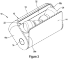
- a headphone case 10 including a shell portion 12 (an example of a housing) and a flap portion 14 (an example of a cover member).
- the shell portion 12 is designed to provide the principal part of the casing defining the storage space for storing headphones therein, whilst the flap portion 14 is designed to complete the enclosure by enclosing the space within the shell portion 12 and allow the user to open or close the headphone case 10 thereby.
- the flap portion 14 and the shell portion 12 are configured to completely enclose the space.
- the shell portion 12 includes a pair of side walls 16a, 16b connected by a top wall 18 and a back wall 20.
- the flap portion 14 defines a front wall of the casing.
- the shell portion 12 and the flap portion 14 have curved end portions downwardly extending from the respective back and front walls and form a continuously curved bottom wall about the hinge point 30 such that the back wall and front wall including these curved end portions define an elongate U-shaped structure.
- the side walls 16a, 16b, the top wall 18 and the back wall 20 define the storage space for storing headphones and together with the front wall created by the flap portion 14 enclose the storage space.
- the flap portion 14 includes a storage structure 22 extending from the inner wall of the flap portion 14. That is, the flap portion 14 may include a door having an inner and an outer side. What is referred to as the inner wall is the inner side in this respect.
- the storage structure 22 extends from the inner wall and into the space defined by the side walls 16a, 16b, the top wall 18 and the back wall 20.
- the storage structure 22 also includes one or more receptacles 24, preferably two in the depicted embodiment, for receiving headphones to be stored.
- the receptacles 24 are shaped and designed such that they are of at least partial complementary shape to the headphones 26 (see Figures 3 and 4 ) to be stored.
- the receptacles 24 are of substantially the same shape as the headphones 26, shown as in-ear headphones, which are stored therein. In this way, the headphones 26 are received within the receptacles 24 to provide frictional engagement, thereby retaining the headphones 26 within the receptacles 24.
- the receptacles 24, and indeed the storage structure 22, may be constructed from any appropriate material, for example a resilient material, to provide the appropriate frictional engagement to retain the headphones 26.
- the storage structure 22 extends from the flap portion 14 by a pair of wings 28a. When in the closed configuration, as shown in Figures 5 and 6 , these wings 28a are not visible.
- the shell portion 12 and the flap portion 14 are connected by way of a pivoting member 30.
- the pivoting member 30 can be any appropriate pivoting, or hinging, means which provides for a point by which the flap portion 14 can pivot, or otherwise rotate, with respect to the shell portion 12.
- the pivoting member 30 is an elongate rod which is located through corresponding holes in the side walls 16a, 16b of the shell portion 12.
- other pivoting members 30 are included and within the scope of the invention.
- the pivoting member 30 allows for the user to open and close the storage case 10.
- the pivoting member 30 allows the user to open the flap portion 14 by rotating it away from the shell portion 12 about an axis defined by the pivoting member 30. In this way, the user can operate the storage case 10 from a closed configuration ( Figures 5 and 6 ) to an open configuration ( Figures 1 - 4 ) and vice versa.
- the construction of the pivoting member 30, together with the shell portion 12 and the flap portion 14, provides a headphone storage case 10 which can be operated with a single hand, or finger, swipe in use. That is to say, the user can operate the case 10 from a closed configuration to an open configuration, and vice versa, by simply "swiping" the case open and closed.
- the storage structure 22 includes a flange 32 (an example of an abutment member) that provides a stop point when the user opens the case 10.
- the flange 32 may cooperate with a lip (not shown, an example of an abutment member) on the innermost side of the top wall 18 of the shell portion 12 to provide a stopping point such that the flap portion 14 cannot be fully rotated away from the shell portion 12. That is, the flange 32 and the lip (not shown) cooperate to restrict the rotational movement of the flap portion 14 with respect to the shell portion 12. This prevents the user from unintentionally removing the flap portion 14, and thus the storage structure 22, from the shell portion 12.
- the storage structure 22 may be sized such that it engages with an inner face of the back wall 20 when the case 10 is in the closed configuration. In this way, the flap portion 14 sits flush, or creates an otherwise continuous surface, with the shell portion 12.
- the flap portion 14 may include a flange such that it prevents the user from pushing the flap portion 14 further into the space enclosed by the shell portion 12. In some embodiments, both configurations may be used simultaneously.
- the headphone case 10 may be constructed from any suitable material, for example plastic or metal.
- the component parts, i.e. the shell portion 12 and flap portion 14, may be constructed from the same or different materials.
Landscapes
- Physics & Mathematics (AREA)
- Engineering & Computer Science (AREA)
- Acoustics & Sound (AREA)
- Signal Processing (AREA)
- Headphones And Earphones (AREA)
- Purses, Travelling Bags, Baskets, Or Suitcases (AREA)
Claims (6)
- System, umfassend:
ein Kopfhörergehäuse (10), umfassend:einen Schalenabschnitt (12), der einen Aufbewahrungsraum zum Aufbewahren von Kopfhörern (26) definiert; undeinen Klappenabschnitt (14), der konfiguriert ist, um den Raum abzuschließen;wobei der Klappenabschnitt (14) mit dem Schalenabschnitt (12) durch ein Schwenkelement (30) verbunden ist und wobei der Klappenabschnitt (14) von einer geschlossenen Konfiguration in eine geöffnete Konfiguration drehbar ist;wobei der Klappenabschnitt (14) eine Aufbewahrungsstruktur (22) einschließt, die sich davon und in den Aufbewahrungsraum erstreckt, wenn in der geschlossenen Konfiguration, wobei die Aufbewahrungsstruktur (22) konfiguriert ist, um Kopfhörer (26) in Verwendung aufzubewahren und umfassend eine oder mehrere Aufnahmen (24) von komplementärer Form zu den Kopfhörern (26), die aufbewahrt werden sollen;wobei die Aufbewahrungsstruktur (22) in der geschlossenen Konfiguration nicht zugänglich ist und wobei die Aufbewahrungsstruktur (22) in der geöffneten Konfiguration zugänglich ist;wobei die Aufbewahrungsstruktur (22) an einer nach innen gerichteten Oberfläche des Klappenabschnitts (14) montiert und/oder einstückig damit ausgebildet ist;wobei sich die Aufbewahrungsstruktur (22) von dem Klappenabschnitt (14) erstreckt und mit einem Paar von vorstehenden Flügeln (28a) einstückig ausgebildet ist, wobei die Flügel (28a, 28b) Seitenwände der Aufbewahrungsstruktur (22) sind und den Klappenabschnitt (14) mit einer Rückwand der Aufbewahrungsstruktur (22) verbinden; unddie Aufbewahrungsstruktur (22) einen Flansch (32) einschließt, um einen Anschlagpunkt derart bereitzustellen, dass der Klappenabschnitt (14) nicht vollständig von dem Schalenabschnitt (12) weggedreht werden kann, wodurch die Drehbewegung des Klappenabschnitts (14) in Bezug auf den Schalenabschnitt (12) eingeschränkt wird; undeinen oder mehrere Kopfhörer (26) in der einen oder den mehreren Aufnahmen (24). - System nach Anspruch 1, wobei der Flansch (32) des Kopfhörergehäuses (10) verhindert, dass der Klappenabschnitt (14) und/oder die Aufbewahrungsstruktur (22) vollständig von dem Schalenabschnitt (12) verschoben werden.
- System nach Anspruch 1 oder 2, wobei der Flansch des Kopfhörergehäuses (10) konfiguriert ist, um mit einer Lippe an einer innersten Seite einer oberen Wand (18) des Schalenabschnitts (12) zusammenzuwirken, um einen Anschlagpunkt bereitzustellen.
- System nach einem der vorstehenden Ansprüche, wobei die eine oder die mehreren Aufnahmen geformt sind (24), um die Kopfhörer (26) in Verwendung aufzunehmen.
- System (10) nach einem der vorstehenden Ansprüche, wobei die Kopfhörer (26) In-Ohr-Kopfhörer sind.
- System (10) nach einem der vorstehenden Ansprüche, wobei der Schalenabschnitt (12) des Kopfhörergehäuses (10) zwei oder mehr gegenüberliegende Seitenwände (16a, 16b) umfasst, wobei jede der Seitenwände (16a, 16b) des Schalenabschnitts (12) ein Loch umfasst und das Schwenkelement (30) eine Stange umfasst, die durch jedes Loch beherbergt ist.
Applications Claiming Priority (2)
| Application Number | Priority Date | Filing Date | Title |
|---|---|---|---|
| GB1816162.0A GB2577712A (en) | 2018-10-03 | 2018-10-03 | Case for headphones |
| PCT/GB2019/052798 WO2020070507A1 (en) | 2018-10-03 | 2019-10-03 | Case for headphones |
Publications (2)
| Publication Number | Publication Date |
|---|---|
| EP3860389A1 EP3860389A1 (de) | 2021-08-11 |
| EP3860389B1 true EP3860389B1 (de) | 2024-04-24 |
Family
ID=68503175
Family Applications (1)
| Application Number | Title | Priority Date | Filing Date |
|---|---|---|---|
| EP19801401.1A Active EP3860389B1 (de) | 2018-10-03 | 2019-10-03 | Gehäuse für kopfhörer |
Country Status (3)
| Country | Link |
|---|---|
| EP (1) | EP3860389B1 (de) |
| GB (1) | GB2577712A (de) |
| WO (1) | WO2020070507A1 (de) |
Families Citing this family (1)
| Publication number | Priority date | Publication date | Assignee | Title |
|---|---|---|---|---|
| CN116546377A (zh) * | 2023-05-26 | 2023-08-04 | 歌尔智能科技有限公司 | 一种耳机盒 |
Citations (2)
| Publication number | Priority date | Publication date | Assignee | Title |
|---|---|---|---|---|
| GB281515A (en) * | 1927-03-04 | 1927-12-08 | Mordan And Company Ltd S | An improved stand or holder for cigarettes and other small articles |
| CN216362352U (zh) * | 2021-04-22 | 2022-04-22 | 东莞市库珀电子有限公司 | 一种便于开合的新式耳机盒 |
Family Cites Families (10)
| Publication number | Priority date | Publication date | Assignee | Title |
|---|---|---|---|---|
| US391145A (en) * | 1888-10-16 | haedin | ||
| US5806678A (en) * | 1997-03-17 | 1998-09-15 | Dalloz Safety Ab | Box for earplugs |
| CN2353342Y (zh) * | 1999-01-28 | 1999-12-15 | 宝山钢铁(集团)公司 | 挂式防噪音耳塞盒 |
| CN201097744Y (zh) * | 2007-08-28 | 2008-08-13 | 中名(东莞)电子有限公司 | 耳机收藏盒 |
| KR101004715B1 (ko) * | 2010-05-12 | 2011-01-04 | 필스전자 주식회사 | 이어폰 패키지 |
| CN102480659A (zh) * | 2010-11-20 | 2012-05-30 | 高彪 | 耳机盒 |
| US8631934B2 (en) * | 2012-02-14 | 2014-01-21 | James K Chun | Multi-functional video device support accessory |
| CN202587332U (zh) * | 2012-04-26 | 2012-12-05 | 季宸昕 | 一种可以保护耳机和耳机接线的耳机线收纳装置 |
| US10117485B2 (en) * | 2015-07-02 | 2018-11-06 | Kurt Solland | Receptacle with pivoting closure |
| CN206948570U (zh) * | 2017-07-19 | 2018-01-30 | 河海大学 | 一种能自动卷线的耳机收纳装置 |
-
2018
- 2018-10-03 GB GB1816162.0A patent/GB2577712A/en not_active Withdrawn
-
2019
- 2019-10-03 EP EP19801401.1A patent/EP3860389B1/de active Active
- 2019-10-03 WO PCT/GB2019/052798 patent/WO2020070507A1/en not_active Ceased
Patent Citations (2)
| Publication number | Priority date | Publication date | Assignee | Title |
|---|---|---|---|---|
| GB281515A (en) * | 1927-03-04 | 1927-12-08 | Mordan And Company Ltd S | An improved stand or holder for cigarettes and other small articles |
| CN216362352U (zh) * | 2021-04-22 | 2022-04-22 | 东莞市库珀电子有限公司 | 一种便于开合的新式耳机盒 |
Also Published As
| Publication number | Publication date |
|---|---|
| GB2577712A (en) | 2020-04-08 |
| EP3860389A1 (de) | 2021-08-11 |
| WO2020070507A1 (en) | 2020-04-09 |
Similar Documents
| Publication | Publication Date | Title |
|---|---|---|
| EP2749382B1 (de) | Werkzeugaufnahmegehäuse und -untergehäuse | |
| JP4881397B2 (ja) | 化粧品容器 | |
| US10117485B2 (en) | Receptacle with pivoting closure | |
| US5975298A (en) | Video cassette container | |
| KR101589086B1 (ko) | 수납용기 | |
| US2869769A (en) | Containers, such as boxes, baskets and the like | |
| US5823337A (en) | Tackle box | |
| WO2014109141A1 (ja) | 冷蔵庫 | |
| KR101102519B1 (ko) | 개폐식 가구용 손잡이 | |
| KR20170039123A (ko) | 보존용기 | |
| EP3860389A1 (de) | Etui für kopfhörer | |
| JP2003189950A (ja) | 扉体付きミラーキャビネット | |
| JP2001349130A (ja) | 保管庫 | |
| CN217005077U (zh) | 用于冰箱的门储存单元及冰箱 | |
| JP7305285B2 (ja) | コンパクト容器 | |
| JP2013023927A (ja) | 収納用ボックス | |
| JP2005132265A (ja) | 車両用コンソールボックス | |
| JP3208152U (ja) | キャリーバッグ | |
| JP7050379B1 (ja) | 宅配ボックス | |
| KR200295035Y1 (ko) | 도어를 갖는 앨범 케이스 | |
| JP3221552U (ja) | 回転取り出し式ギターケース | |
| JPH10332258A (ja) | 食品貯蔵装置 | |
| JP2023174280A (ja) | コンパクト容器 | |
| JP2017084908A (ja) | 筐体 | |
| JP2024070688A (ja) | 配達物収納箱 |
Legal Events
| Date | Code | Title | Description |
|---|---|---|---|
| STAA | Information on the status of an ep patent application or granted ep patent |
Free format text: STATUS: UNKNOWN |
|
| STAA | Information on the status of an ep patent application or granted ep patent |
Free format text: STATUS: THE INTERNATIONAL PUBLICATION HAS BEEN MADE |
|
| PUAI | Public reference made under article 153(3) epc to a published international application that has entered the european phase |
Free format text: ORIGINAL CODE: 0009012 |
|
| STAA | Information on the status of an ep patent application or granted ep patent |
Free format text: STATUS: REQUEST FOR EXAMINATION WAS MADE |
|
| 17P | Request for examination filed |
Effective date: 20210430 |
|
| AK | Designated contracting states |
Kind code of ref document: A1 Designated state(s): AL AT BE BG CH CY CZ DE DK EE ES FI FR GB GR HR HU IE IS IT LI LT LU LV MC MK MT NL NO PL PT RO RS SE SI SK SM TR |
|
| DAV | Request for validation of the european patent (deleted) | ||
| DAX | Request for extension of the european patent (deleted) | ||
| RIN1 | Information on inventor provided before grant (corrected) |
Inventor name: GUYAN, HEATHER Inventor name: KEATING, DAVID Inventor name: PRENTICE, SAM Inventor name: HUTCHISON, KYLE Inventor name: WANG, JO-YUN |
|
| STAA | Information on the status of an ep patent application or granted ep patent |
Free format text: STATUS: EXAMINATION IS IN PROGRESS |
|
| 17Q | First examination report despatched |
Effective date: 20220325 |
|
| GRAP | Despatch of communication of intention to grant a patent |
Free format text: ORIGINAL CODE: EPIDOSNIGR1 |
|
| STAA | Information on the status of an ep patent application or granted ep patent |
Free format text: STATUS: GRANT OF PATENT IS INTENDED |
|
| INTG | Intention to grant announced |
Effective date: 20231113 |
|
| GRAS | Grant fee paid |
Free format text: ORIGINAL CODE: EPIDOSNIGR3 |
|
| P01 | Opt-out of the competence of the unified patent court (upc) registered |
Effective date: 20240213 |
|
| GRAA | (expected) grant |
Free format text: ORIGINAL CODE: 0009210 |
|
| STAA | Information on the status of an ep patent application or granted ep patent |
Free format text: STATUS: THE PATENT HAS BEEN GRANTED |
|
| AK | Designated contracting states |
Kind code of ref document: B1 Designated state(s): AL AT BE BG CH CY CZ DE DK EE ES FI FR GB GR HR HU IE IS IT LI LT LU LV MC MK MT NL NO PL PT RO RS SE SI SK SM TR |
|
| REG | Reference to a national code |
Ref country code: GB Ref legal event code: FG4D |
|
| REG | Reference to a national code |
Ref country code: CH Ref legal event code: EP |
|
| REG | Reference to a national code |
Ref country code: DE Ref legal event code: R096 Ref document number: 602019050992 Country of ref document: DE |
|
| REG | Reference to a national code |
Ref country code: IE Ref legal event code: FG4D |
|
| REG | Reference to a national code |
Ref country code: LT Ref legal event code: MG9D |
|
| REG | Reference to a national code |
Ref country code: NL Ref legal event code: MP Effective date: 20240424 |
|
| REG | Reference to a national code |
Ref country code: AT Ref legal event code: MK05 Ref document number: 1678606 Country of ref document: AT Kind code of ref document: T Effective date: 20240424 |
|
| PG25 | Lapsed in a contracting state [announced via postgrant information from national office to epo] |
Ref country code: NL Free format text: LAPSE BECAUSE OF FAILURE TO SUBMIT A TRANSLATION OF THE DESCRIPTION OR TO PAY THE FEE WITHIN THE PRESCRIBED TIME-LIMIT Effective date: 20240424 |
|
| PG25 | Lapsed in a contracting state [announced via postgrant information from national office to epo] |
Ref country code: NL Free format text: LAPSE BECAUSE OF FAILURE TO SUBMIT A TRANSLATION OF THE DESCRIPTION OR TO PAY THE FEE WITHIN THE PRESCRIBED TIME-LIMIT Effective date: 20240424 |
|
| PG25 | Lapsed in a contracting state [announced via postgrant information from national office to epo] |
Ref country code: IS Free format text: LAPSE BECAUSE OF FAILURE TO SUBMIT A TRANSLATION OF THE DESCRIPTION OR TO PAY THE FEE WITHIN THE PRESCRIBED TIME-LIMIT Effective date: 20240824 |
|
| PG25 | Lapsed in a contracting state [announced via postgrant information from national office to epo] |
Ref country code: BG Free format text: LAPSE BECAUSE OF FAILURE TO SUBMIT A TRANSLATION OF THE DESCRIPTION OR TO PAY THE FEE WITHIN THE PRESCRIBED TIME-LIMIT Effective date: 20240424 |
|
| PG25 | Lapsed in a contracting state [announced via postgrant information from national office to epo] |
Ref country code: HR Free format text: LAPSE BECAUSE OF FAILURE TO SUBMIT A TRANSLATION OF THE DESCRIPTION OR TO PAY THE FEE WITHIN THE PRESCRIBED TIME-LIMIT Effective date: 20240424 Ref country code: FI Free format text: LAPSE BECAUSE OF FAILURE TO SUBMIT A TRANSLATION OF THE DESCRIPTION OR TO PAY THE FEE WITHIN THE PRESCRIBED TIME-LIMIT Effective date: 20240424 |
|
| PG25 | Lapsed in a contracting state [announced via postgrant information from national office to epo] |
Ref country code: GR Free format text: LAPSE BECAUSE OF FAILURE TO SUBMIT A TRANSLATION OF THE DESCRIPTION OR TO PAY THE FEE WITHIN THE PRESCRIBED TIME-LIMIT Effective date: 20240725 |
|
| PG25 | Lapsed in a contracting state [announced via postgrant information from national office to epo] |
Ref country code: PT Free format text: LAPSE BECAUSE OF FAILURE TO SUBMIT A TRANSLATION OF THE DESCRIPTION OR TO PAY THE FEE WITHIN THE PRESCRIBED TIME-LIMIT Effective date: 20240826 |
|
| PG25 | Lapsed in a contracting state [announced via postgrant information from national office to epo] |
Ref country code: ES Free format text: LAPSE BECAUSE OF FAILURE TO SUBMIT A TRANSLATION OF THE DESCRIPTION OR TO PAY THE FEE WITHIN THE PRESCRIBED TIME-LIMIT Effective date: 20240424 |
|
| PG25 | Lapsed in a contracting state [announced via postgrant information from national office to epo] |
Ref country code: AT Free format text: LAPSE BECAUSE OF FAILURE TO SUBMIT A TRANSLATION OF THE DESCRIPTION OR TO PAY THE FEE WITHIN THE PRESCRIBED TIME-LIMIT Effective date: 20240424 |
|
| PG25 | Lapsed in a contracting state [announced via postgrant information from national office to epo] |
Ref country code: PL Free format text: LAPSE BECAUSE OF FAILURE TO SUBMIT A TRANSLATION OF THE DESCRIPTION OR TO PAY THE FEE WITHIN THE PRESCRIBED TIME-LIMIT Effective date: 20240424 |
|
| PG25 | Lapsed in a contracting state [announced via postgrant information from national office to epo] |
Ref country code: LV Free format text: LAPSE BECAUSE OF FAILURE TO SUBMIT A TRANSLATION OF THE DESCRIPTION OR TO PAY THE FEE WITHIN THE PRESCRIBED TIME-LIMIT Effective date: 20240424 |
|
| PG25 | Lapsed in a contracting state [announced via postgrant information from national office to epo] |
Ref country code: PT Free format text: LAPSE BECAUSE OF FAILURE TO SUBMIT A TRANSLATION OF THE DESCRIPTION OR TO PAY THE FEE WITHIN THE PRESCRIBED TIME-LIMIT Effective date: 20240826 Ref country code: PL Free format text: LAPSE BECAUSE OF FAILURE TO SUBMIT A TRANSLATION OF THE DESCRIPTION OR TO PAY THE FEE WITHIN THE PRESCRIBED TIME-LIMIT Effective date: 20240424 Ref country code: NO Free format text: LAPSE BECAUSE OF FAILURE TO SUBMIT A TRANSLATION OF THE DESCRIPTION OR TO PAY THE FEE WITHIN THE PRESCRIBED TIME-LIMIT Effective date: 20240724 Ref country code: LV Free format text: LAPSE BECAUSE OF FAILURE TO SUBMIT A TRANSLATION OF THE DESCRIPTION OR TO PAY THE FEE WITHIN THE PRESCRIBED TIME-LIMIT Effective date: 20240424 Ref country code: IS Free format text: LAPSE BECAUSE OF FAILURE TO SUBMIT A TRANSLATION OF THE DESCRIPTION OR TO PAY THE FEE WITHIN THE PRESCRIBED TIME-LIMIT Effective date: 20240824 Ref country code: HR Free format text: LAPSE BECAUSE OF FAILURE TO SUBMIT A TRANSLATION OF THE DESCRIPTION OR TO PAY THE FEE WITHIN THE PRESCRIBED TIME-LIMIT Effective date: 20240424 Ref country code: GR Free format text: LAPSE BECAUSE OF FAILURE TO SUBMIT A TRANSLATION OF THE DESCRIPTION OR TO PAY THE FEE WITHIN THE PRESCRIBED TIME-LIMIT Effective date: 20240725 Ref country code: FI Free format text: LAPSE BECAUSE OF FAILURE TO SUBMIT A TRANSLATION OF THE DESCRIPTION OR TO PAY THE FEE WITHIN THE PRESCRIBED TIME-LIMIT Effective date: 20240424 Ref country code: ES Free format text: LAPSE BECAUSE OF FAILURE TO SUBMIT A TRANSLATION OF THE DESCRIPTION OR TO PAY THE FEE WITHIN THE PRESCRIBED TIME-LIMIT Effective date: 20240424 Ref country code: BG Free format text: LAPSE BECAUSE OF FAILURE TO SUBMIT A TRANSLATION OF THE DESCRIPTION OR TO PAY THE FEE WITHIN THE PRESCRIBED TIME-LIMIT Effective date: 20240424 Ref country code: AT Free format text: LAPSE BECAUSE OF FAILURE TO SUBMIT A TRANSLATION OF THE DESCRIPTION OR TO PAY THE FEE WITHIN THE PRESCRIBED TIME-LIMIT Effective date: 20240424 Ref country code: RS Free format text: LAPSE BECAUSE OF FAILURE TO SUBMIT A TRANSLATION OF THE DESCRIPTION OR TO PAY THE FEE WITHIN THE PRESCRIBED TIME-LIMIT Effective date: 20240724 |
|
| PG25 | Lapsed in a contracting state [announced via postgrant information from national office to epo] |
Ref country code: DK Free format text: LAPSE BECAUSE OF FAILURE TO SUBMIT A TRANSLATION OF THE DESCRIPTION OR TO PAY THE FEE WITHIN THE PRESCRIBED TIME-LIMIT Effective date: 20240424 |
|
| PG25 | Lapsed in a contracting state [announced via postgrant information from national office to epo] |
Ref country code: EE Free format text: LAPSE BECAUSE OF FAILURE TO SUBMIT A TRANSLATION OF THE DESCRIPTION OR TO PAY THE FEE WITHIN THE PRESCRIBED TIME-LIMIT Effective date: 20240424 |
|
| PG25 | Lapsed in a contracting state [announced via postgrant information from national office to epo] |
Ref country code: CZ Free format text: LAPSE BECAUSE OF FAILURE TO SUBMIT A TRANSLATION OF THE DESCRIPTION OR TO PAY THE FEE WITHIN THE PRESCRIBED TIME-LIMIT Effective date: 20240424 |
|
| PG25 | Lapsed in a contracting state [announced via postgrant information from national office to epo] |
Ref country code: SK Free format text: LAPSE BECAUSE OF FAILURE TO SUBMIT A TRANSLATION OF THE DESCRIPTION OR TO PAY THE FEE WITHIN THE PRESCRIBED TIME-LIMIT Effective date: 20240424 Ref country code: RO Free format text: LAPSE BECAUSE OF FAILURE TO SUBMIT A TRANSLATION OF THE DESCRIPTION OR TO PAY THE FEE WITHIN THE PRESCRIBED TIME-LIMIT Effective date: 20240424 |
|
| REG | Reference to a national code |
Ref country code: DE Ref legal event code: R097 Ref document number: 602019050992 Country of ref document: DE |
|
| PG25 | Lapsed in a contracting state [announced via postgrant information from national office to epo] |
Ref country code: SM Free format text: LAPSE BECAUSE OF FAILURE TO SUBMIT A TRANSLATION OF THE DESCRIPTION OR TO PAY THE FEE WITHIN THE PRESCRIBED TIME-LIMIT Effective date: 20240424 |
|
| PG25 | Lapsed in a contracting state [announced via postgrant information from national office to epo] |
Ref country code: SM Free format text: LAPSE BECAUSE OF FAILURE TO SUBMIT A TRANSLATION OF THE DESCRIPTION OR TO PAY THE FEE WITHIN THE PRESCRIBED TIME-LIMIT Effective date: 20240424 Ref country code: SK Free format text: LAPSE BECAUSE OF FAILURE TO SUBMIT A TRANSLATION OF THE DESCRIPTION OR TO PAY THE FEE WITHIN THE PRESCRIBED TIME-LIMIT Effective date: 20240424 Ref country code: RO Free format text: LAPSE BECAUSE OF FAILURE TO SUBMIT A TRANSLATION OF THE DESCRIPTION OR TO PAY THE FEE WITHIN THE PRESCRIBED TIME-LIMIT Effective date: 20240424 Ref country code: EE Free format text: LAPSE BECAUSE OF FAILURE TO SUBMIT A TRANSLATION OF THE DESCRIPTION OR TO PAY THE FEE WITHIN THE PRESCRIBED TIME-LIMIT Effective date: 20240424 Ref country code: DK Free format text: LAPSE BECAUSE OF FAILURE TO SUBMIT A TRANSLATION OF THE DESCRIPTION OR TO PAY THE FEE WITHIN THE PRESCRIBED TIME-LIMIT Effective date: 20240424 Ref country code: CZ Free format text: LAPSE BECAUSE OF FAILURE TO SUBMIT A TRANSLATION OF THE DESCRIPTION OR TO PAY THE FEE WITHIN THE PRESCRIBED TIME-LIMIT Effective date: 20240424 |
|
| PLBE | No opposition filed within time limit |
Free format text: ORIGINAL CODE: 0009261 |
|
| STAA | Information on the status of an ep patent application or granted ep patent |
Free format text: STATUS: NO OPPOSITION FILED WITHIN TIME LIMIT |
|
| 26N | No opposition filed |
Effective date: 20250127 |
|
| PG25 | Lapsed in a contracting state [announced via postgrant information from national office to epo] |
Ref country code: SI Free format text: LAPSE BECAUSE OF FAILURE TO SUBMIT A TRANSLATION OF THE DESCRIPTION OR TO PAY THE FEE WITHIN THE PRESCRIBED TIME-LIMIT Effective date: 20240424 |
|
| PGFP | Annual fee paid to national office [announced via postgrant information from national office to epo] |
Ref country code: GB Payment date: 20250123 Year of fee payment: 6 |
|
| REG | Reference to a national code |
Ref country code: DE Ref legal event code: R119 Ref document number: 602019050992 Country of ref document: DE |
|
| REG | Reference to a national code |
Ref country code: CH Ref legal event code: PL |
|
| PG25 | Lapsed in a contracting state [announced via postgrant information from national office to epo] |
Ref country code: MC Free format text: LAPSE BECAUSE OF FAILURE TO SUBMIT A TRANSLATION OF THE DESCRIPTION OR TO PAY THE FEE WITHIN THE PRESCRIBED TIME-LIMIT Effective date: 20240424 |
|
| PG25 | Lapsed in a contracting state [announced via postgrant information from national office to epo] |
Ref country code: DE Free format text: LAPSE BECAUSE OF NON-PAYMENT OF DUE FEES Effective date: 20250501 |
|
| PG25 | Lapsed in a contracting state [announced via postgrant information from national office to epo] |
Ref country code: BE Free format text: LAPSE BECAUSE OF NON-PAYMENT OF DUE FEES Effective date: 20241031 Ref country code: LU Free format text: LAPSE BECAUSE OF NON-PAYMENT OF DUE FEES Effective date: 20241003 |
|
| PG25 | Lapsed in a contracting state [announced via postgrant information from national office to epo] |
Ref country code: FR Free format text: LAPSE BECAUSE OF NON-PAYMENT OF DUE FEES Effective date: 20241031 |
|
| PG25 | Lapsed in a contracting state [announced via postgrant information from national office to epo] |
Ref country code: CH Free format text: LAPSE BECAUSE OF NON-PAYMENT OF DUE FEES Effective date: 20241031 |
|
| REG | Reference to a national code |
Ref country code: BE Ref legal event code: MM Effective date: 20241031 |
|
| PG25 | Lapsed in a contracting state [announced via postgrant information from national office to epo] |
Ref country code: SE Free format text: LAPSE BECAUSE OF FAILURE TO SUBMIT A TRANSLATION OF THE DESCRIPTION OR TO PAY THE FEE WITHIN THE PRESCRIBED TIME-LIMIT Effective date: 20240424 |
|
| PG25 | Lapsed in a contracting state [announced via postgrant information from national office to epo] |
Ref country code: IE Free format text: LAPSE BECAUSE OF NON-PAYMENT OF DUE FEES Effective date: 20241003 |
|
| PG25 | Lapsed in a contracting state [announced via postgrant information from national office to epo] |
Ref country code: CY Free format text: LAPSE BECAUSE OF FAILURE TO SUBMIT A TRANSLATION OF THE DESCRIPTION OR TO PAY THE FEE WITHIN THE PRESCRIBED TIME-LIMIT; INVALID AB INITIO Effective date: 20191003 Ref country code: IT Free format text: LAPSE BECAUSE OF FAILURE TO SUBMIT A TRANSLATION OF THE DESCRIPTION OR TO PAY THE FEE WITHIN THE PRESCRIBED TIME-LIMIT Effective date: 20240424 |
|
| PG25 | Lapsed in a contracting state [announced via postgrant information from national office to epo] |
Ref country code: HU Free format text: LAPSE BECAUSE OF FAILURE TO SUBMIT A TRANSLATION OF THE DESCRIPTION OR TO PAY THE FEE WITHIN THE PRESCRIBED TIME-LIMIT; INVALID AB INITIO Effective date: 20191003 |