EP3860420B1 - Système de nettoyage et procédé de nettoyage d'articles à nettoyer - Google Patents
Système de nettoyage et procédé de nettoyage d'articles à nettoyer Download PDFInfo
- Publication number
- EP3860420B1 EP3860420B1 EP19783294.2A EP19783294A EP3860420B1 EP 3860420 B1 EP3860420 B1 EP 3860420B1 EP 19783294 A EP19783294 A EP 19783294A EP 3860420 B1 EP3860420 B1 EP 3860420B1
- Authority
- EP
- European Patent Office
- Prior art keywords
- cleaning
- conveyor device
- conveyor
- washware
- transport
- Prior art date
- Legal status (The legal status is an assumption and is not a legal conclusion. Google has not performed a legal analysis and makes no representation as to the accuracy of the status listed.)
- Active
Links
Images


Classifications
-
- A—HUMAN NECESSITIES
- A47—FURNITURE; DOMESTIC ARTICLES OR APPLIANCES; COFFEE MILLS; SPICE MILLS; SUCTION CLEANERS IN GENERAL
- A47L—DOMESTIC WASHING OR CLEANING; SUCTION CLEANERS IN GENERAL
- A47L15/00—Washing or rinsing machines for crockery or tableware
- A47L15/24—Washing or rinsing machines for crockery or tableware with movement of the crockery baskets by conveyors
-
- A—HUMAN NECESSITIES
- A47—FURNITURE; DOMESTIC ARTICLES OR APPLIANCES; COFFEE MILLS; SPICE MILLS; SUCTION CLEANERS IN GENERAL
- A47L—DOMESTIC WASHING OR CLEANING; SUCTION CLEANERS IN GENERAL
- A47L15/00—Washing or rinsing machines for crockery or tableware
- A47L15/24—Washing or rinsing machines for crockery or tableware with movement of the crockery baskets by conveyors
- A47L15/241—Washing or rinsing machines for crockery or tableware with movement of the crockery baskets by conveyors the dishes moving in a horizontal plane
-
- A—HUMAN NECESSITIES
- A47—FURNITURE; DOMESTIC ARTICLES OR APPLIANCES; COFFEE MILLS; SPICE MILLS; SUCTION CLEANERS IN GENERAL
- A47L—DOMESTIC WASHING OR CLEANING; SUCTION CLEANERS IN GENERAL
- A47L15/00—Washing or rinsing machines for crockery or tableware
- A47L15/24—Washing or rinsing machines for crockery or tableware with movement of the crockery baskets by conveyors
- A47L15/241—Washing or rinsing machines for crockery or tableware with movement of the crockery baskets by conveyors the dishes moving in a horizontal plane
- A47L15/245—Washing or rinsing machines for crockery or tableware with movement of the crockery baskets by conveyors the dishes moving in a horizontal plane the dishes being placed directly on the conveyors, i.e. not in dish racks
-
- A—HUMAN NECESSITIES
- A47—FURNITURE; DOMESTIC ARTICLES OR APPLIANCES; COFFEE MILLS; SPICE MILLS; SUCTION CLEANERS IN GENERAL
- A47L—DOMESTIC WASHING OR CLEANING; SUCTION CLEANERS IN GENERAL
- A47L2401/00—Automatic detection in controlling methods of washing or rinsing machines for crockery or tableware, e.g. information provided by sensors entered into controlling devices
- A47L2401/30—Variation of electrical, magnetical or optical quantities
-
- A—HUMAN NECESSITIES
- A47—FURNITURE; DOMESTIC ARTICLES OR APPLIANCES; COFFEE MILLS; SPICE MILLS; SUCTION CLEANERS IN GENERAL
- A47L—DOMESTIC WASHING OR CLEANING; SUCTION CLEANERS IN GENERAL
- A47L2401/00—Automatic detection in controlling methods of washing or rinsing machines for crockery or tableware, e.g. information provided by sensors entered into controlling devices
- A47L2401/34—Other automatic detections
-
- A—HUMAN NECESSITIES
- A47—FURNITURE; DOMESTIC ARTICLES OR APPLIANCES; COFFEE MILLS; SPICE MILLS; SUCTION CLEANERS IN GENERAL
- A47L—DOMESTIC WASHING OR CLEANING; SUCTION CLEANERS IN GENERAL
- A47L2501/00—Output in controlling method of washing or rinsing machines for crockery or tableware, i.e. quantities or components controlled, or actions performed by the controlling device executing the controlling method
- A47L2501/24—Conveyor belts, e.g. conveyor belts motors
Definitions
- the invention relates to a cleaning system and a method for cleaning items to be cleaned.
- Cleaning systems and methods of the aforementioned type can be used, for example, in the field of dishwashing technology, particularly in the field of commercial dishwashing technology.
- the invention can be used in particular in commercial kitchens where items to be cleaned, such as trays, dishes, and cutlery, must be cleaned in large quantities.
- other areas of application are also conceivable in principle.
- cleaning devices also referred to as cleaning appliances, which can clean and/or disinfect cleaning items.
- the design of these cleaning devices depends largely on the various boundary conditions, such as the type of cleaning item to be cleaned, the contamination, the throughput, or similar conditions. Examples include cleaning devices which, for example, are used in DE 10 2004 056 052 A1 or in DE 10 2007 025 263 A1 are described.
- a technical and organizational challenge in many cases is that the contaminated cleaning items are not distributed evenly. Due in particular to group dynamics, timetables, or other circumstances beyond the control of the commercial kitchen, peak loads often occur, but so do times when little or no cleaning items are required. This poses a significant challenge for staff planning and the design of the cleaning equipment.
- the system and personnel planning must generally be designed so that staff can cope with peak loads, which, however, may lead to underutilization of staff outside of peak loads. Therefore, staff planning and the design of the cleaning equipment must in many cases be oversized.
- a dishwasher in the form of a commercial utensil or dishwashing machine designed as a programmable automatic machine, which is configured as a hood-type or pass-through dishwasher and has a treatment chamber with at least one washing system designed as a recirculation system.
- the dishwasher is assigned a loading/unloading device for preferably selectively automatically loading the treatment chamber with items to be washed and/or for preferably selectively automatically unloading items to be washed from the treatment chamber.
- KR 10 1 327 580 B1 Describes an automation system for dishwashers in which food trays and containers (soup bowls, rice bowls, side plates, lids, etc.) are separated by sprockets from a food tray guide carrier installed in the main body. The containers are guided through a drop hole of the food tray guide carrier for transfer to the first and second transfer conveyors installed below. Precision washing of the upper and lower parts of containers is performed automatically by incorporating a washing section into the middle section, and contaminated water is reused by further installing a filter circulator.
- a cleaning system for cleaning items to be cleaned comprises at least one cleaning device and at least one transport system as components.
- cleaning device is a broad term to which its usual and common meaning should be attributed, as understood by a person skilled in the art.
- the term is not limited to a specific or adapted meaning.
- the term can, without limitation, refer in particular to a device designed to free items to be cleaned of adhering macroscopic or even microscopic contaminants or to at least partially remove such contaminants.
- a disinfecting effect can optionally be exerted.
- the cleaning device can, as explained in more detail below, be designed in particular as a dishwasher, in particular as a dishwashing machine.
- the dishwasher can be designed, for example, as a single-chamber dishwasher, in particular as a commercial single-chamber dishwasher with a multi-circuit washing system, or as a conveyor dishwasher, in particular as a flight-type dishwasher and/or as a rack-type dishwasher. Examples are explained in more detail below.
- the term "item to be cleaned,” as used here, is a broad term to which its usual and common meaning should be attributed, as understood by a person skilled in the art.
- the term is not limited to a specific or adapted meaning.
- the term can, without limitation, refer in particular to any objects that can be cleaned by means of the cleaning device.
- One object can be cleaned, or several objects can be cleaned simultaneously or sequentially.
- the item to be cleaned can be objects that are used directly or indirectly for the preparation, storage, or presentation of food, for example, dishes, cutlery, trays, bowls, glasses, pots, pans, or similar objects.
- the cleaning device can be designed in particular as a dishwasher, for example, as a dishwasher for commercial use in large-scale kitchens or kitchens for communal catering. Other designs of the item to be cleaned are also possible in principle.
- the cleaning device has at least one at least partially closed cleaning chamber with at least one application device for applying at least one cleaning liquid to the items to be cleaned.
- the term "application device,” as used here, is a broad term to which its usual and common meaning should be attributed, as understood by a person skilled in the art. The term is not limited to a specific or adapted meaning. The term can, without limitation, refer in particular to any device by means of which the items to be cleaned within the cleaning chamber can be exposed to the cleaning fluid.
- the application device can, in particular, as explained in more detail below, comprise at least one nozzle system.
- the application device can comprise at least one pump and at least one line system for supplying cleaning fluid to the nozzle system.
- a nozzle system and a line system for applying cleaning fluid from a tank can be provided, as well as at least one corresponding pump.
- the sensor can detect that at least a first area of the second conveyor device cannot be occupied, but that at least a second area arranged perpendicular to the conveying direction next to the first area can be occupied, and can then transfer the items to be transferred accordingly into this second area.
- the cleaning system for example the transport system, can have at least one controller that is programmatically configured to control this transfer. Different types of cleaning items can also be distinguished, since the term "occupyable" can also depend, for example, on the type of cleaning item. For example, a free area of the second conveyor device may be suitable for plates, but too small for trays and thus not suitable for use.
- the controller can, for example, recognize the suitability for the type of cleaning item currently being transferred and control the transfer accordingly and/or select cleaning items that are suitable for transfer.
- the first conveyor device and the second conveyor device can, in particular, be arranged in relation to one another in such a way that they intersect.
- the first conveyor device can, in particular, be arranged at least partially above the second conveyor device and, for example, intersect it in at least one transfer area.
- the transfer device can, in particular, include a transfer between different levels.
- the transfer device can have at least one chute for the contaminated cleaning material, which, for example, in at least one transfer area, effects a transfer between the first conveyor device and the second conveyor device, at least partially due to gravity.
- the transfer device can, however, also comprise, for example, at least one actuator. and/or at least one conveyor belt.
- the transfer area can be fixed in one location or, optionally, spatially variable.
- the transfer device can further comprise at least one brake for the contaminated items to be cleaned.
- the transport system can be configured to close the brake if an occupied area of the second conveyor device is detected by the sensor and the items to be cleaned would be transferred to the occupied area of the second conveyor device if the brake were open.
- the brake can, for example, comprise a barrier that prevents the items to be cleaned from further transport or transfer. For example, this at least one barrier can be arranged in front of, at, or on the chute described above, or at another location on the first conveyor device, the second conveyor device, or the transfer device.
- the brake can, in particular, be part of a lock for the items to be cleaned.
- the lock can, in particular, comprise the brake as a front lock gate facing the second conveyor device, wherein the lock can optionally further comprise a rear lock gate facing the first conveyor device.
- the second conveyor device can, in particular, have at least two occupable tracks arranged parallel to one another.
- the term "track,” as used here, is a broad term to which its usual and common meaning should be given, as understood by those skilled in the art. The term is not limited to a specific or adapted meaning.
- the term can, without limitation, refer in particular to the fact that several pieces of cleaning material can be arranged in a direction perpendicular to a transport direction of the second conveyor device, so that, viewed in the transport direction, they are arranged next to one another on the second conveyor device. Each of the adjacent pieces then occupies a track.
- the second conveyor device for example, a conveyor belt, can then be virtually or actually divided into strips parallel to the transport direction, each strip having, for example, the width of a piece of cleaning material. Depending on the type of cleaning material, these strips can vary in width.
- the transfer device can, in particular, comprise at least one switch configured to direct the items to be cleaned to different lanes, for example, depending on which lane the sensor has detected an occupable area on.
- switch is a broad term to which its usual and common meaning should be attributed, as understood by those skilled in the art. The term is not limited to any specific or adapted meaning.
- the term can, without limitation, refer in particular to a device which is configured to selectively direct the movement of at least one object onto one of at least two tracks.
- the switch can in particular comprise at least one guide element which can be adjusted in an angular position and which can direct the object onto one track or another track depending on the angular position.
- the second conveying device can, in particular, comprise a conveyor belt.
- This can, for example, be a continuous conveyor belt or, for example, a conveyor belt divided into links, or a conveyor chain or link chain.
- the conveyor belt can be flat or, for example, have receiving compartments, such as transport fingers.
- the areas that can be occupied can, in particular, be free areas on the conveyor belt.
- the second conveyor device can, in particular, comprise a transport device for baskets for cleaning items, also referred to as transport baskets, dish baskets, or dishwashing baskets.
- This transport device can, for example, comprise a plurality of transport fingers or other types of carriers that can interact with the baskets and carry them along.
- the occupyable areas can, in particular, be free areas in the baskets for cleaning items.
- the cleaning device can, in particular, comprise at least one dishwasher.
- the dishwasher can, in particular, be selected from the group consisting of: a rack-type dishwasher, a conveyor-type dishwasher, a hood-type dishwasher, and a pass-through dishwasher.
- the first conveyor device and the second conveyor device can, in particular, run parallel to each other at least in a transfer area.
- the transfer area can be the area in which the items to be cleaned are transferred from the first conveyor device to the second conveyor device. This transfer area can be fixed. be by the transfer device or also be variable, especially if the transfer device is not stationary.
- the cleaning chamber can, in particular, be configured at least partially as a cleaning tunnel.
- the cleaning device can, in particular, have at least two cleaning zones in the cleaning tunnel.
- the transport system can, in particular, be configured, for example, by means of the second conveyor device or by means of a third conveyor device assigned to the cleaning device, to transport the items to be cleaned sequentially through the cleaning zones.
- the cleaning zones can, in particular, comprise at least two zones selected from the group consisting of: a pre-clearing zone, a washing zone, a pumped rinsing zone, a fresh water rinsing zone, and a drying zone.
- the cleaning system may further comprise at least one controller.
- controller as used here, is a broad term to which its usual and common meaning should be attributed, as understood by a person skilled in the art. The term is not limited to a specific or adapted meaning. The term may, without limitation, refer in particular to a single-part or multi-part device of the cleaning system or cleaning device, which is configured to completely or partially control and/or regulate the operation of the cleaning system, in particular of the cleaning device and/or the transport system.
- the controller may be configured to change, in particular to control and/or regulate, one or more operating parameters of the cleaning system, for example, at least one temperature, at least one pressure, at least one heating power, at least one transport speed, or a combination of two or more of the aforementioned operating parameters.
- the cleaning device and the transport system may have separate controllers, a common controller, or two or more coupled controllers.
- the controller may, in particular, comprise at least a data processing device, for example at least one processor.
- the controller can in particular be set up using programming, for example to control at least one cleaning program of the cleaning device and optionally to control or carry out the proposed method in one or more of the embodiments mentioned below.
- the controller can be implemented entirely or partially using hardware or/and, alternatively or additionally, entirely or partially using software.
- the controller can comprise at least one volatile and/or non-volatile data memory.
- the controller can comprise at least one interface, for example a human-machine interface for inputting commands and/or outputting information, and/or a wireless or wired interface for the unidirectional or bidirectional exchange of data and/or commands between the cleaning device and at least one further device.
- the controller can in particular comprise at least one computer and/or at least one processor.
- the controller can in particular be a central or decentralized machine control of the cleaning device and/or the cleaning system and/or the transport system.
- the controller can in particular be set up using programming to control operation of the transport system and in particular also of the cleaning device.
- the controller can also be connected to the sensor and, for example, process one or more sensor signals using programming.
- the senor can generally comprise one or more sensors.
- the sensor can comprise at least one sensor selected from the group consisting of: an optical sensor; a camera; a metal detector; a light barrier; a mechanical button; and an electromagnetic sensor.
- the sensor can, for example, be connected directly or indirectly to the controller so that the controller can, for example, evaluate sensor signals.
- the controller can detect occupable areas.
- the controller can have an image data analysis system that automatically detects occupable areas, for example using a self-learning algorithm and/or artificial intelligence.
- the transfer device can, for example, move the transfer area opposite to a transport direction of the second conveyor, so that the transfer area is moved away from the cleaning device, whereby the first conveyor can, for example, continue to operate.
- the second conveyor has to be stopped, for example, contaminated cleaning items can be transported from a drop-off point by the first conveyor, thus avoiding annoying congestion for a canteen user, for example.
- this method also allows for the effective use of timed cleaning devices in canteen operations, since the first conveyor can continue to operate continuously even if the second conveyor stops for a short time.
- the transport system 116 in this embodiment comprises a transfer device 126 for transferring at least a portion of the contaminated cleaning material 112 from the first conveyor device 118 to the second conveyor device 120 in a transfer area 127.
- the transport system 116 in this embodiment comprises at least one sensor 128 for detecting assignable areas 130 on the second conveyor device 120.
- the transport system 116 is configured to control the transfer device 126 such that the contaminated cleaning material 112 is transferred exclusively to the assignable areas 130 of the second conveyor device 120.
- the cleaning system 110 can, for example, have a corresponding A controller 132, which is coupled, for example, to the sensor 128, evaluates its signals, thereby detecting occupable areas 130, and controls the transfer device 126 accordingly locally and temporally.
- the senor 128, as explained in more detail below, can comprise at least one camera 176 and/or at least one position sensor 178, wherein, for example, the camera 176 itself and/or the controller 132 can have image recognition to detect the occupable areas 130.
- Other configurations of the at least one sensor 128 are also possible.
- the cleaning device 114 can be designed, for example, as a conveyor dishwasher, for example a rack conveyor dishwasher and/or a flight conveyor dishwasher. Other designs are also possible, for example, program machines with discontinuous operation, for example pass-through dishwashers in the form of hood-type dishwashers or the like. In this case, the control of the transport system 116 should be adapted to the program operation. Without limiting further designs, the cleaning device 114 is described below with reference to conveyor dishwashers. In general, for possible designs of such conveyor dishwashers, which can be modified and/or supplemented according to the invention, for example, DE 10 2004 046 758 A1 , DE 10 2007 053 381 B3 or DE 10 2009 035 668 A1 However, other configurations are also possible in principle.
- the cleaning device 114 has the cleaning chamber 122 in the form of a cleaning tunnel 134.
- the cleaning tunnel 134 can be divided, in particular by dividing curtains 136, into several zones 138, also referred to as cleaning zones.
- a pre-clearing zone 140, a rinsing zone 142, a final rinse zone 144, and a drying zone 146 are provided, for example.
- the final rinse zone 144 can, for example, be further subdivided into a pumped final rinse zone and a fresh water final rinse zone.
- Other configurations of the zones 138 are also possible.
- the cleaning material 112 can be subjected to at least one cleaning liquid by means of at least one application device 148.
- a pre-clearing zone nozzle system 150 can be provided for this purpose in the pre-clearing zone 140, which, for example, via a Figure 1 not shown pump and a not shown pipe system, can be fed with cleaning fluid from a pre-cleaning tank 152.
- a rinsing zone nozzle system 154 can be provided, which, for example via a pump (also not shown) and a line system (also not shown), can be fed with cleaning fluid from a rinsing tank 156.
- at least one rinse nozzle system 158 can be provided, for example, which can be fed with heated fresh water and/or with rinse fluid from a rinse tank 160.
- the items to be cleaned 112 can then enter the drying zone 146, in which the items to be cleaned 112 can be exposed to warm air, for example via a fan 162, in order to accelerate the drying of the items to be cleaned 112.
- the cleaning stock 112 is transported by means of the third conveyor device 124 in a transport direction 164 from an inlet area 166 through the cleaning chamber 122 to an outlet area 168.
- the outlet area 168 is located downstream of the cleaning chamber 122 in the transport direction 164, so that the cleaned cleaning stock 112 can be removed from the third conveyor device 124 in the outlet area 168.
- the cleaned cleaning stock 112 can be separated and fed manually or automatically to one or more storage devices.
- the conveyor dishwasher can be configured, for example, as a rack-type dishwasher, in which the items 112 to be cleaned are transported by means of items baskets 170, also referred to as transport baskets.
- items baskets 170 also referred to as transport baskets.
- other types of cleaning devices 114 can also be used, as explained above, for example, flight-type dishwashers and/or timed-controlled dishwashers, such as program-controlled machines, in particular hood-type dishwashers.
- the type of transport and/or the type of transfer device 126 and the at least one sensor 128 can be adapted to the type of transport and/or to the type of items 112 to be cleaned.
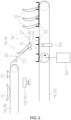
- FIG 2 a transfer area of the cleaning system 110 according to Figure 1 shown in an enlarged schematic representation.
- the transfer device 126 is specifically adapted for basket transport as an example.
- adaptation to other types of transport, such as belt transport, is also possible.
- the second conveyor device 120 can, for example, be operated continuously or discontinuously, for example intermittently.
- the second conveyor device 120 can be operated intermittently as a whole or only in sections.
- the second conveyor device 120 can, as shown in Figure 2 shown, optionally have at least one motor 180 for timing transport baskets 170.
- the controller 132 can, for example, open the brake 174 so that items to be cleaned 112 can slide from the chute 172 into the respective area that can be occupied 130.
- the brake 174 may be part of a lock 182.
- This lock 182 may, for example, have the brake 174 as a front lock gate 184 and additionally a rear lock gate 186 facing the first conveyor device 118.
- the lock gates 184, 186 can, for example, be designed as simple flaps.
- the lock 182 can, for example, prevent a backlog of cleaning items 112 from forming on the chute 172, as well as prevent more than one piece of the cleaning items 112 from being transferred to an accessible area 130.
- the transfer device with the chute 172 and the lock 182 is exemplary configured to detect areas 130 that can be occupied in the longitudinal direction, i.e. in the direction of transport direction 164, and to occupy them with cleaning material 112. Alternatively or additionally, however, distribution and thus occupation can also take place transversely to the transport direction 164.
- This is exemplary shown in Figure 3 shown using a flight conveyor dishwasher. However, an analogous design can also be used in other systems, for example in the rack conveyor dishwasher according to the Figures 1 and 2 .
- the second conveyor device 120 is designed in this exemplary embodiment as a conveyor belt, with a plurality of transport fingers 188, which can receive the cleaning item 112 in an upright position.
- a plurality of transport fingers 188 which can receive the cleaning item 112 in an upright position.
- several pieces of the cleaning material 112 can be received next to one another at the same longitudinal position in the transport direction 164.
- the conveyor belt can be virtually divided into two or more tracks 190, 192, wherein each track can receive a piece of the cleaning material 112 at a position in the transport direction 164.
- the transfer device 126 can, for example, alternatively or in addition to the lock 182, have at least one switch 194.
- This switch 194 can, for example, have one or more wings 196, 198, which can, for example, be pivotably mounted about axes 200, 202. In this way or by means of other actuators, the switch 194 can be configured to direct the cleaning material 112 to different tracks 190, 192.
- the switch 194 can be controlled, for example, by the controller 132, depending, for example, on a detection of occupable areas 130 by the at least one sensor 128, for example the camera 176.
Landscapes
- Washing And Drying Of Tableware (AREA)
- Cleaning By Liquid Or Steam (AREA)
Claims (15)
- Système de nettoyage (110) destiné au nettoyage d'objets à nettoyer (112), comprenanta) au moins un dispositif de nettoyage (114), possédant au moins une chambre de nettoyage (122) au moins partiellement fermée pourvue d'au moins un dispositif d'exposition (148) destiné à exposer les objets à nettoyer (112) à au moins un liquide de nettoyage ; etb) au moins un système de transport (116) destiné au transport automatique des objets à nettoyer (112), le système de transport (116) comprenant :le système de transport (116) étant conçu pour commander le dispositif de transfert (126) de telle sorte que les objets à nettoyer (112) encrassés soient transférés exclusivement sur les zones occupables (130) du deuxième dispositif de convoyage (120).a. au moins un premier dispositif de convoyage (118) destiné à l'amenée des objets à nettoyer (112) encrassés ;b. au moins un deuxième dispositif de convoyage (120) destiné au transport des objets à nettoyer (112) encrassés vers le dispositif de nettoyage (114) ;c. au moins un dispositif de transfert (126) destiné au transfert d'au moins une partie des objets à nettoyer (112) encrassés du premier dispositif de convoyage (118) vers le deuxième dispositif de convoyage (120) ; etd. au moins un capteur (128) destiné à la reconnaissance des zones occupables (130) sur le deuxième dispositif de convoyage (120), les zones occupables (130) étant des zones qui ne sont pas encore ou pas suffisamment occupées par des objets à nettoyer (112) et qui peuvent par conséquent recevoir des objets à nettoyer (112) supplémentaires ;
- Système de nettoyage (110) selon la revendication précédente, le premier dispositif de convoyage (118) étant disposé au moins partiellement au-dessus du deuxième dispositif de convoyage (120), le dispositif de transfert (126) possédant au moins une glissière (172) pour les objets à nettoyer (112) encrassés.
- Système de nettoyage (110) selon l'une des revendications précédentes, le dispositif de transfert (126) possédant en outre au moins un frein (174) pour les objets à nettoyer (112) encrassés, le système de transport (116) étant conçu pour fermer le frein (174) lorsqu'une zone occupée (130) du deuxième dispositif de convoyage (120) est détectée au moyen du capteur (128) et que les objets à nettoyer (112) seraient transférés sur la zone occupée (130) du deuxième dispositif de convoyage (120) avec le frein (174) ouvert.
- Système de nettoyage (110) selon la revendication précédente, le frein (174) faisant partie intégrante d'un sas (182) pour les objets à nettoyer (112), le sas possédant le frein (174) en tant que porte de sas avant (184) qui fait face au deuxième dispositif de convoyage (120), le sas (182) possédant en outre une porte arrière (186) qui fait face au premier dispositif de convoyage (118).
- Système de nettoyage (110) selon l'une des revendications précédentes, le deuxième dispositif de convoyage (120) possédant au moins deux voies occupables (190, 192) disposées parallèlement l'une à l'autre, le dispositif de transfert (126) possédant au moins un aiguillage (194), l'aiguillage (194) étant conçu pour diriger les objets à nettoyer (112) sur différentes voies (190, 192).
- Système de nettoyage (110) selon l'une des revendications précédentes, le deuxième dispositif de convoyage (120) possédant une bande transporteuse, les zones occupables (130) étant des zones libres sur la bande transporteuse.
- Système de nettoyage (110) selon l'une des revendications précédentes, le deuxième dispositif de convoyage (120) possédant un dispositif de transport pour des paniers à objets à nettoyer (170), les zones occupables (130) étant des zones libres dans les paniers à objets à nettoyer (170).
- Système de nettoyage (110) selon l'une des revendications précédentes, le dispositif de nettoyage (114) comprenant au moins un lave-vaisselle.
- Système de nettoyage (110) selon la revendication précédente, le lave-vaisselle étant choisi parmi le groupe comprenant : une machine de transport à panier, une machine de transport à bande, un lave-vaisselle à capot, un lave-vaisselle à passage en continu.
- Système de nettoyage (110) selon l'une des revendications précédentes, le premier dispositif de convoyage (118) et le deuxième dispositif de convoyage (120) suivant un tracé parallèle l'un à l'autre au moins dans une zone de transfert (127).
- Système de nettoyage (110) selon l'une des revendications précédentes, la chambre de nettoyage (122) étant configurée au moins partiellement en tant que tunnel de nettoyage (134), le dispositif de nettoyage (114) possédant au moins deux zones de nettoyage (138, 140, 142, 144) dans le tunnel de nettoyage (134), le système de transport (116) étant conçu, en particulier au moyen du deuxième dispositif de convoyage (120), pour transporter séquentiellement les objets à nettoyer (112) à travers les zones de nettoyage (138, 140, 142, 144).
- Système de nettoyage (110) selon l'une des revendications précédentes, le dispositif de nettoyage (114) possédant au moins un troisième dispositif de convoyage (124), le troisième dispositif de convoyage (124) étant adjacent au deuxième dispositif de convoyage (120) et étant conçu pour transporter les objets à nettoyer (112) à travers la chambre de nettoyage (122).
- Système de nettoyage (110) selon l'une des revendications précédentes, le système de nettoyage (110) comprenant en outre une commande (132), la commande (132) étant configurée par programmation pour commander un fonctionnement du système de transport (116).
- Système de nettoyage (110) selon l'une des revendications précédentes, capteur (128) comprenant au moins un capteur (128) choisi parmi le groupe constitué de : un capteur optique ; une caméra ; un détecteur de métaux ; une barrière photoélectrique ; un palpeur mécanique ; un capteur électromagnétique.
- Procédé pour nettoyer des objets à nettoyer (112), comprenant les étapes suivantes :I. fourniture d'un système de nettoyage (110) selon l'une des revendications précédentes ;II. amenée des objets à nettoyer (112) encrassés à l'aide du premier dispositif de convoyage (118) ;III. reconnaissance de zones occupables (130) sur le deuxième dispositif de convoyage (120) ; etIV. transfert d'au moins une partie des objets à nettoyer (112) encrassés au moyen du dispositif de transfert (126) vers les zones occupables (130) du deuxième dispositif de convoyage (120).
Priority Applications (1)
| Application Number | Priority Date | Filing Date | Title |
|---|---|---|---|
| EP25179057.2A EP4616777A3 (fr) | 2018-10-05 | 2019-10-04 | Système de nettoyage et procédé de nettoyage d'un produit à nettoyer |
Applications Claiming Priority (2)
| Application Number | Priority Date | Filing Date | Title |
|---|---|---|---|
| DE102018217058.4A DE102018217058B4 (de) | 2018-10-05 | 2018-10-05 | Reinigungssystem und Verfahren zur Reinigung von Reinigungsgut |
| PCT/EP2019/076884 WO2020070272A1 (fr) | 2018-10-05 | 2019-10-04 | Système de nettoyage et procédé de nettoyage d'articles à nettoyer |
Related Child Applications (2)
| Application Number | Title | Priority Date | Filing Date |
|---|---|---|---|
| EP25179057.2A Division EP4616777A3 (fr) | 2018-10-05 | 2019-10-04 | Système de nettoyage et procédé de nettoyage d'un produit à nettoyer |
| EP25179057.2A Division-Into EP4616777A3 (fr) | 2018-10-05 | 2019-10-04 | Système de nettoyage et procédé de nettoyage d'un produit à nettoyer |
Publications (2)
| Publication Number | Publication Date |
|---|---|
| EP3860420A1 EP3860420A1 (fr) | 2021-08-11 |
| EP3860420B1 true EP3860420B1 (fr) | 2025-07-02 |
Family
ID=68159121
Family Applications (2)
| Application Number | Title | Priority Date | Filing Date |
|---|---|---|---|
| EP19783294.2A Active EP3860420B1 (fr) | 2018-10-05 | 2019-10-04 | Système de nettoyage et procédé de nettoyage d'articles à nettoyer |
| EP25179057.2A Pending EP4616777A3 (fr) | 2018-10-05 | 2019-10-04 | Système de nettoyage et procédé de nettoyage d'un produit à nettoyer |
Family Applications After (1)
| Application Number | Title | Priority Date | Filing Date |
|---|---|---|---|
| EP25179057.2A Pending EP4616777A3 (fr) | 2018-10-05 | 2019-10-04 | Système de nettoyage et procédé de nettoyage d'un produit à nettoyer |
Country Status (4)
| Country | Link |
|---|---|
| EP (2) | EP3860420B1 (fr) |
| DE (1) | DE102018217058B4 (fr) |
| ES (1) | ES3042583T3 (fr) |
| WO (1) | WO2020070272A1 (fr) |
Families Citing this family (6)
| Publication number | Priority date | Publication date | Assignee | Title |
|---|---|---|---|---|
| DE102020114364A1 (de) * | 2020-05-28 | 2021-12-02 | Illinois Tool Works Inc. | System zum beladen mindestens einer transportspülmaschine mit spülgutteilen, anordnung aus mindestens einer transportspülmaschine und einem beladesystem sowie verfahren zum beladen mindestens einer transportspülmaschine mit spülgutteilen |
| CN113040679B (zh) * | 2021-04-02 | 2022-05-24 | 义乌工商职业技术学院 | 一种清洗水再利用烤盘清洗设备 |
| EP4074238A1 (fr) * | 2021-04-15 | 2022-10-19 | Ali Group S.r.l. | Machine tunnel multifonction pour désinfecter de la vaisselle et procédé associé |
| CN116784740A (zh) * | 2022-03-17 | 2023-09-22 | 深圳市普渡科技有限公司 | 智能洗碗机及智能清洗系统 |
| IT202300013821A1 (it) * | 2023-07-03 | 2025-01-03 | Ali Div S R L | Macchina a tunnel multifunzione per la sanificazione di articoli da tavola e metodo correlato |
| WO2026008846A1 (fr) | 2024-07-05 | 2026-01-08 | Meiko Maschinenbau Gmbh & Co. Kg | Lave-vaisselle à convoyeur et procédé de nettoyage d'articles à nettoyer |
Family Cites Families (16)
| Publication number | Priority date | Publication date | Assignee | Title |
|---|---|---|---|---|
| US3486939A (en) * | 1967-10-17 | 1969-12-30 | Charles P Pinckard | Apparatus for classifying,cleaning and collecting culinary items |
| DE1928650C3 (de) * | 1969-06-06 | 1978-05-11 | Inventio Ag, Hergiswil, Nidwalden (Schweiz) | Einrichtung zum automatischen Beladen eines Transportbandes einer Bandspülmaschine |
| DE9319034U1 (de) * | 1992-11-16 | 1994-03-24 | Winterhalter Gastronom Gmbh, 88074 Meckenbeuren | Geschirrspülmaschine |
| DE102004046758A1 (de) * | 2004-09-24 | 2006-04-06 | Meiko Maschinenbau Gmbh & Co. Kg | Verfahren und Anordnung zum energiesparenden Betrieb von Spülmaschinen |
| DE102004049392A1 (de) * | 2004-10-08 | 2006-04-13 | Meiko Maschinenbau Gmbh & Co.Kg | Verfahren zum Transport von Reinigungsgut durch eine Durchlaufspülmaschine und Durchlaufspülmaschine |
| DE102004056052A1 (de) * | 2004-11-19 | 2006-06-01 | Meiko Maschinenbau Gmbh & Co. Kg | Verfahren zur Beurteilung und Sicherstellung von thermischer Hygienewirkung |
| DE102007025263A1 (de) * | 2007-05-30 | 2007-10-31 | Meiko Maschinenbau Gmbh & Co. Kg | Reinigungsgerät mit Keimreduktion durch Mikrowellen |
| DE102007053381B3 (de) * | 2007-11-09 | 2009-04-02 | Meiko Maschinenbau Gmbh & Co.Kg | Geschirrspülmaschine mit Latentwärmespeicher |
| EP2158833A2 (fr) * | 2008-08-22 | 2010-03-03 | MEIKO Maschinenbau GmbH & Co. KG | Lave-vaisselle doté d'un appareil de manipulation sur le plateau à vaisselle |
| KR100977943B1 (ko) * | 2009-03-31 | 2010-08-24 | 명순승 | 식기세척기의 식판 자동투입장치 |
| DE102009035668A1 (de) * | 2009-07-30 | 2011-02-03 | Meiko Maschinenbau Gmbh & Co. Kg | Energieoptimierte Maschinensteuerung für Reinigungsvorrichtungen |
| DE102011004853B4 (de) * | 2011-02-28 | 2014-11-27 | Premark Feg L.L.C. (N.D.Ges.D. Staates Delaware) | Fördervorrichtung zum Zuführen von Spülgut an eine Transportspülmaschine |
| WO2013191650A1 (fr) * | 2012-06-19 | 2013-12-27 | Jcs-Echigo Pte Ltd | Procédé de lavage d'articles amélioré et appareil correspondant |
| KR101327580B1 (ko) * | 2013-04-22 | 2013-11-20 | 명순승 | 식기세척기 자동화시스템 |
| KR101487193B1 (ko) * | 2013-08-06 | 2015-02-02 | (주)신진마스타 | 동조제어장치가 구비된 식기세척장비 |
| DE102017121978A1 (de) * | 2017-09-22 | 2017-11-30 | Illinois Tool Works Inc. | Spülmaschine |
-
2018
- 2018-10-05 DE DE102018217058.4A patent/DE102018217058B4/de active Active
-
2019
- 2019-10-04 EP EP19783294.2A patent/EP3860420B1/fr active Active
- 2019-10-04 WO PCT/EP2019/076884 patent/WO2020070272A1/fr not_active Ceased
- 2019-10-04 EP EP25179057.2A patent/EP4616777A3/fr active Pending
- 2019-10-04 ES ES19783294T patent/ES3042583T3/es active Active
Also Published As
| Publication number | Publication date |
|---|---|
| DE102018217058B4 (de) | 2020-12-17 |
| WO2020070272A1 (fr) | 2020-04-09 |
| EP4616777A3 (fr) | 2025-12-17 |
| DE102018217058A1 (de) | 2020-04-09 |
| EP3860420A1 (fr) | 2021-08-11 |
| EP4616777A2 (fr) | 2025-09-17 |
| ES3042583T3 (en) | 2025-11-21 |
Similar Documents
| Publication | Publication Date | Title |
|---|---|---|
| DE102018217058B4 (de) | Reinigungssystem und Verfahren zur Reinigung von Reinigungsgut | |
| EP3107438B1 (fr) | Dispositif de nettoyage adapté aux besoins | |
| DE102011004853B4 (de) | Fördervorrichtung zum Zuführen von Spülgut an eine Transportspülmaschine | |
| DE102009012566B4 (de) | Durchlauf-Spülmaschine mit Chargenerkennung und Chargendokumentation | |
| EP2866635B1 (fr) | Dispositif de nettoyage comprenant un système de buse de rinçage final à déclenchement individuel | |
| EP2158833A2 (fr) | Lave-vaisselle doté d'un appareil de manipulation sur le plateau à vaisselle | |
| EP3840626B1 (fr) | Système de nettoyage et procédé de nettoyage de produit à nettoyer | |
| DE102013226080B4 (de) | Reinigungsvorrichtung und Verfahren zum Reinigen von Reinigungsgut | |
| EP3906834B1 (fr) | Système de chargement de différentes voies de transport d'au moins une bobinoir et agencement de bobinoir doté d'un tel système | |
| DE102019102800A1 (de) | System zum Beladen einer Spülmaschine und Spülmaschine mit einem derartigen System | |
| EP3860419B1 (fr) | Dispositif de nettoyage et procédé de nettoyage d'articles à nettoyer | |
| DE102020214604A1 (de) | Sortiersystem zum Sortieren von Besteckteilen | |
| EP4072393B1 (fr) | Système modulaire de chargement d'un lave-vaisselle à convoyeur | |
| EP3915456B1 (fr) | Système de chargement de vaisselles dans au moins un lave-vaisselle mobile, agencement d'au moins un lave-vaisselle mobile et d'un système de chargement, ainsi que procédé de chargement de vaisselles dans au moins un lave-vaisselle mobile | |
| EP3870015B1 (fr) | Système de nettoyage et procédé de nettoyage d'article à nettoyer | |
| DE102018214073A1 (de) | Reinigungsvorrichtung und Verfahren zur Reinigung von Reinigungsgut | |
| CA3117087C (fr) | Systeme de nettoyage et procede de nettoyage d'article a nettoyer | |
| WO2024256610A1 (fr) | Dispositif de nettoyage et procédé de nettoyage d'articles à nettoyer | |
| EP4596465A1 (fr) | Système de chargement pour charger une machine de rinçage de transport avec des pièces de vaisselle et dispositif pour nettoyer au moins partiellement automatiquement des pièces de vaisselle avec un système de chargement |
Legal Events
| Date | Code | Title | Description |
|---|---|---|---|
| STAA | Information on the status of an ep patent application or granted ep patent |
Free format text: STATUS: UNKNOWN |
|
| STAA | Information on the status of an ep patent application or granted ep patent |
Free format text: STATUS: THE INTERNATIONAL PUBLICATION HAS BEEN MADE |
|
| PUAI | Public reference made under article 153(3) epc to a published international application that has entered the european phase |
Free format text: ORIGINAL CODE: 0009012 |
|
| STAA | Information on the status of an ep patent application or granted ep patent |
Free format text: STATUS: REQUEST FOR EXAMINATION WAS MADE |
|
| 17P | Request for examination filed |
Effective date: 20210415 |
|
| AK | Designated contracting states |
Kind code of ref document: A1 Designated state(s): AL AT BE BG CH CY CZ DE DK EE ES FI FR GB GR HR HU IE IS IT LI LT LU LV MC MK MT NL NO PL PT RO RS SE SI SK SM TR |
|
| DAV | Request for validation of the european patent (deleted) | ||
| DAX | Request for extension of the european patent (deleted) | ||
| GRAP | Despatch of communication of intention to grant a patent |
Free format text: ORIGINAL CODE: EPIDOSNIGR1 |
|
| STAA | Information on the status of an ep patent application or granted ep patent |
Free format text: STATUS: GRANT OF PATENT IS INTENDED |
|
| INTG | Intention to grant announced |
Effective date: 20250128 |
|
| GRAS | Grant fee paid |
Free format text: ORIGINAL CODE: EPIDOSNIGR3 |
|
| GRAA | (expected) grant |
Free format text: ORIGINAL CODE: 0009210 |
|
| STAA | Information on the status of an ep patent application or granted ep patent |
Free format text: STATUS: THE PATENT HAS BEEN GRANTED |
|
| AK | Designated contracting states |
Kind code of ref document: B1 Designated state(s): AL AT BE BG CH CY CZ DE DK EE ES FI FR GB GR HR HU IE IS IT LI LT LU LV MC MK MT NL NO PL PT RO RS SE SI SK SM TR |
|
| REG | Reference to a national code |
Ref country code: GB Ref legal event code: FG4D Free format text: NOT ENGLISH |
|
| REG | Reference to a national code |
Ref country code: CH Ref legal event code: EP |
|
| REG | Reference to a national code |
Ref country code: DE Ref legal event code: R096 Ref document number: 502019013563 Country of ref document: DE |
|
| P01 | Opt-out of the competence of the unified patent court (upc) registered |
Free format text: CASE NUMBER: APP_29684/2025 Effective date: 20250623 |
|
| REG | Reference to a national code |
Ref country code: IE Ref legal event code: FG4D Free format text: LANGUAGE OF EP DOCUMENT: GERMAN |
|
| REG | Reference to a national code |
Ref country code: SE Ref legal event code: TRGR |
|
| REG | Reference to a national code |
Ref country code: NL Ref legal event code: FP |
|
| REG | Reference to a national code |
Ref country code: CH Ref legal event code: U11 Free format text: ST27 STATUS EVENT CODE: U-0-0-U10-U11 (AS PROVIDED BY THE NATIONAL OFFICE) Effective date: 20251101 |
|
| PGFP | Annual fee paid to national office [announced via postgrant information from national office to epo] |
Ref country code: NL Payment date: 20251024 Year of fee payment: 7 |
|
| REG | Reference to a national code |
Ref country code: ES Ref legal event code: FG2A Ref document number: 3042583 Country of ref document: ES Kind code of ref document: T3 Effective date: 20251121 |
|
| PG25 | Lapsed in a contracting state [announced via postgrant information from national office to epo] |
Ref country code: PT Free format text: LAPSE BECAUSE OF FAILURE TO SUBMIT A TRANSLATION OF THE DESCRIPTION OR TO PAY THE FEE WITHIN THE PRESCRIBED TIME-LIMIT Effective date: 20251103 |
|
| PG25 | Lapsed in a contracting state [announced via postgrant information from national office to epo] |
Ref country code: IS Free format text: LAPSE BECAUSE OF FAILURE TO SUBMIT A TRANSLATION OF THE DESCRIPTION OR TO PAY THE FEE WITHIN THE PRESCRIBED TIME-LIMIT Effective date: 20251102 |
|
| PGFP | Annual fee paid to national office [announced via postgrant information from national office to epo] |
Ref country code: DE Payment date: 20251030 Year of fee payment: 7 |
|
| PGFP | Annual fee paid to national office [announced via postgrant information from national office to epo] |
Ref country code: GB Payment date: 20251024 Year of fee payment: 7 |
|
| PG25 | Lapsed in a contracting state [announced via postgrant information from national office to epo] |
Ref country code: NO Free format text: LAPSE BECAUSE OF FAILURE TO SUBMIT A TRANSLATION OF THE DESCRIPTION OR TO PAY THE FEE WITHIN THE PRESCRIBED TIME-LIMIT Effective date: 20251002 |
|
| REG | Reference to a national code |
Ref country code: LT Ref legal event code: MG9D |
|
| PGFP | Annual fee paid to national office [announced via postgrant information from national office to epo] |
Ref country code: AT Payment date: 20251023 Year of fee payment: 7 |
|
| PG25 | Lapsed in a contracting state [announced via postgrant information from national office to epo] |
Ref country code: FI Free format text: LAPSE BECAUSE OF FAILURE TO SUBMIT A TRANSLATION OF THE DESCRIPTION OR TO PAY THE FEE WITHIN THE PRESCRIBED TIME-LIMIT Effective date: 20250702 |
|
| PGFP | Annual fee paid to national office [announced via postgrant information from national office to epo] |
Ref country code: IT Payment date: 20251030 Year of fee payment: 7 |
|
| PG25 | Lapsed in a contracting state [announced via postgrant information from national office to epo] |
Ref country code: HR Free format text: LAPSE BECAUSE OF FAILURE TO SUBMIT A TRANSLATION OF THE DESCRIPTION OR TO PAY THE FEE WITHIN THE PRESCRIBED TIME-LIMIT Effective date: 20250702 |
|
| PGFP | Annual fee paid to national office [announced via postgrant information from national office to epo] |
Ref country code: FR Payment date: 20251024 Year of fee payment: 7 |
|
| PG25 | Lapsed in a contracting state [announced via postgrant information from national office to epo] |
Ref country code: GR Free format text: LAPSE BECAUSE OF FAILURE TO SUBMIT A TRANSLATION OF THE DESCRIPTION OR TO PAY THE FEE WITHIN THE PRESCRIBED TIME-LIMIT Effective date: 20251003 |
|
| PGFP | Annual fee paid to national office [announced via postgrant information from national office to epo] |
Ref country code: SE Payment date: 20251024 Year of fee payment: 7 Ref country code: CH Payment date: 20251101 Year of fee payment: 7 |
|
| PG25 | Lapsed in a contracting state [announced via postgrant information from national office to epo] |
Ref country code: CZ Free format text: LAPSE BECAUSE OF FAILURE TO SUBMIT A TRANSLATION OF THE DESCRIPTION OR TO PAY THE FEE WITHIN THE PRESCRIBED TIME-LIMIT Effective date: 20250702 |
|
| PG25 | Lapsed in a contracting state [announced via postgrant information from national office to epo] |
Ref country code: LV Free format text: LAPSE BECAUSE OF FAILURE TO SUBMIT A TRANSLATION OF THE DESCRIPTION OR TO PAY THE FEE WITHIN THE PRESCRIBED TIME-LIMIT Effective date: 20250702 |
|
| PG25 | Lapsed in a contracting state [announced via postgrant information from national office to epo] |
Ref country code: BG Free format text: LAPSE BECAUSE OF FAILURE TO SUBMIT A TRANSLATION OF THE DESCRIPTION OR TO PAY THE FEE WITHIN THE PRESCRIBED TIME-LIMIT Effective date: 20250702 Ref country code: PL Free format text: LAPSE BECAUSE OF FAILURE TO SUBMIT A TRANSLATION OF THE DESCRIPTION OR TO PAY THE FEE WITHIN THE PRESCRIBED TIME-LIMIT Effective date: 20250702 |
|
| PG25 | Lapsed in a contracting state [announced via postgrant information from national office to epo] |
Ref country code: RS Free format text: LAPSE BECAUSE OF FAILURE TO SUBMIT A TRANSLATION OF THE DESCRIPTION OR TO PAY THE FEE WITHIN THE PRESCRIBED TIME-LIMIT Effective date: 20251002 |
|
| PGFP | Annual fee paid to national office [announced via postgrant information from national office to epo] |
Ref country code: ES Payment date: 20251103 Year of fee payment: 7 |
|
| PG25 | Lapsed in a contracting state [announced via postgrant information from national office to epo] |
Ref country code: RO Free format text: LAPSE BECAUSE OF FAILURE TO SUBMIT A TRANSLATION OF THE DESCRIPTION OR TO PAY THE FEE WITHIN THE PRESCRIBED TIME-LIMIT Effective date: 20250702 |
|
| REG | Reference to a national code |
Ref country code: DE Ref legal event code: R026 Ref document number: 502019013563 Country of ref document: DE |
|
| PLBI | Opposition filed |
Free format text: ORIGINAL CODE: 0009260 |
|
| REG | Reference to a national code |
Ref country code: CH Ref legal event code: L10 Free format text: ST27 STATUS EVENT CODE: U-0-0-L10-L00 (AS PROVIDED BY THE NATIONAL OFFICE) Effective date: 20260402 |
|
| PG25 | Lapsed in a contracting state [announced via postgrant information from national office to epo] |
Ref country code: SM Free format text: LAPSE BECAUSE OF FAILURE TO SUBMIT A TRANSLATION OF THE DESCRIPTION OR TO PAY THE FEE WITHIN THE PRESCRIBED TIME-LIMIT Effective date: 20250702 |
|
| PG25 | Lapsed in a contracting state [announced via postgrant information from national office to epo] |
Ref country code: DK Free format text: LAPSE BECAUSE OF FAILURE TO SUBMIT A TRANSLATION OF THE DESCRIPTION OR TO PAY THE FEE WITHIN THE PRESCRIBED TIME-LIMIT Effective date: 20250702 |
|
| PLAX | Notice of opposition and request to file observation + time limit sent |
Free format text: ORIGINAL CODE: EPIDOSNOBS2 |
|
| PG25 | Lapsed in a contracting state [announced via postgrant information from national office to epo] |
Ref country code: EE Free format text: LAPSE BECAUSE OF FAILURE TO SUBMIT A TRANSLATION OF THE DESCRIPTION OR TO PAY THE FEE WITHIN THE PRESCRIBED TIME-LIMIT Effective date: 20250702 Ref country code: SK Free format text: LAPSE BECAUSE OF FAILURE TO SUBMIT A TRANSLATION OF THE DESCRIPTION OR TO PAY THE FEE WITHIN THE PRESCRIBED TIME-LIMIT Effective date: 20250702 |
|
| 26 | Opposition filed |
Opponent name: HOBART GMBH Effective date: 20260319 |