EP3861199B1 - Deformation eines ventilsitzes zur verbesserung einer schmierölpumpeneinheit und schmiersystem eines grossen langsam laufenden zweitaktmotors - Google Patents
Deformation eines ventilsitzes zur verbesserung einer schmierölpumpeneinheit und schmiersystem eines grossen langsam laufenden zweitaktmotors Download PDFInfo
- Publication number
- EP3861199B1 EP3861199B1 EP19783421.1A EP19783421A EP3861199B1 EP 3861199 B1 EP3861199 B1 EP 3861199B1 EP 19783421 A EP19783421 A EP 19783421A EP 3861199 B1 EP3861199 B1 EP 3861199B1
- Authority
- EP
- European Patent Office
- Prior art keywords
- valve
- seat
- lubricant
- injection
- lubricator
- Prior art date
- Legal status (The legal status is an assumption and is not a legal conclusion. Google has not performed a legal analysis and makes no representation as to the accuracy of the status listed.)
- Active
Links
Images



Classifications
-
- F—MECHANICAL ENGINEERING; LIGHTING; HEATING; WEAPONS; BLASTING
- F01—MACHINES OR ENGINES IN GENERAL; ENGINE PLANTS IN GENERAL; STEAM ENGINES
- F01M—LUBRICATING OF MACHINES OR ENGINES IN GENERAL; LUBRICATING INTERNAL COMBUSTION ENGINES; CRANKCASE VENTILATING
- F01M1/00—Pressure lubrication
- F01M1/08—Lubricating systems characterised by the provision therein of lubricant jetting means
-
- F—MECHANICAL ENGINEERING; LIGHTING; HEATING; WEAPONS; BLASTING
- F01—MACHINES OR ENGINES IN GENERAL; ENGINE PLANTS IN GENERAL; STEAM ENGINES
- F01M—LUBRICATING OF MACHINES OR ENGINES IN GENERAL; LUBRICATING INTERNAL COMBUSTION ENGINES; CRANKCASE VENTILATING
- F01M1/00—Pressure lubrication
- F01M1/16—Controlling lubricant pressure or quantity
-
- F—MECHANICAL ENGINEERING; LIGHTING; HEATING; WEAPONS; BLASTING
- F16—ENGINEERING ELEMENTS AND UNITS; GENERAL MEASURES FOR PRODUCING AND MAINTAINING EFFECTIVE FUNCTIONING OF MACHINES OR INSTALLATIONS; THERMAL INSULATION IN GENERAL
- F16N—LUBRICATING
- F16N13/00—Lubricating-pumps
- F16N13/02—Lubricating-pumps with reciprocating piston
- F16N13/04—Adjustable reciprocating pumps
-
- F—MECHANICAL ENGINEERING; LIGHTING; HEATING; WEAPONS; BLASTING
- F16—ENGINEERING ELEMENTS AND UNITS; GENERAL MEASURES FOR PRODUCING AND MAINTAINING EFFECTIVE FUNCTIONING OF MACHINES OR INSTALLATIONS; THERMAL INSULATION IN GENERAL
- F16N—LUBRICATING
- F16N13/00—Lubricating-pumps
- F16N13/02—Lubricating-pumps with reciprocating piston
- F16N13/06—Actuation of lubricating-pumps
- F16N13/16—Actuation of lubricating-pumps with fluid drive
-
- F—MECHANICAL ENGINEERING; LIGHTING; HEATING; WEAPONS; BLASTING
- F16—ENGINEERING ELEMENTS AND UNITS; GENERAL MEASURES FOR PRODUCING AND MAINTAINING EFFECTIVE FUNCTIONING OF MACHINES OR INSTALLATIONS; THERMAL INSULATION IN GENERAL
- F16N—LUBRICATING
- F16N29/00—Special means in lubricating arrangements or systems providing for the indication or detection of undesired conditions; Use of devices responsive to conditions in lubricating arrangements or systems
- F16N29/02—Special means in lubricating arrangements or systems providing for the indication or detection of undesired conditions; Use of devices responsive to conditions in lubricating arrangements or systems for influencing the supply of lubricant
-
- F—MECHANICAL ENGINEERING; LIGHTING; HEATING; WEAPONS; BLASTING
- F16—ENGINEERING ELEMENTS AND UNITS; GENERAL MEASURES FOR PRODUCING AND MAINTAINING EFFECTIVE FUNCTIONING OF MACHINES OR INSTALLATIONS; THERMAL INSULATION IN GENERAL
- F16N—LUBRICATING
- F16N7/00—Arrangements for supplying oil or unspecified lubricant from a stationary reservoir or the equivalent in or on the machine or member to be lubricated
- F16N7/38—Arrangements for supplying oil or unspecified lubricant from a stationary reservoir or the equivalent in or on the machine or member to be lubricated with a separate pump; Central lubrication systems
- F16N7/385—Central lubrication systems
-
- F—MECHANICAL ENGINEERING; LIGHTING; HEATING; WEAPONS; BLASTING
- F01—MACHINES OR ENGINES IN GENERAL; ENGINE PLANTS IN GENERAL; STEAM ENGINES
- F01M—LUBRICATING OF MACHINES OR ENGINES IN GENERAL; LUBRICATING INTERNAL COMBUSTION ENGINES; CRANKCASE VENTILATING
- F01M1/00—Pressure lubrication
- F01M1/08—Lubricating systems characterised by the provision therein of lubricant jetting means
- F01M2001/083—Lubricating systems characterised by the provision therein of lubricant jetting means for lubricating cylinders
-
- F—MECHANICAL ENGINEERING; LIGHTING; HEATING; WEAPONS; BLASTING
- F02—COMBUSTION ENGINES; HOT-GAS OR COMBUSTION-PRODUCT ENGINE PLANTS
- F02D—CONTROLLING COMBUSTION ENGINES
- F02D2400/00—Control systems adapted for specific engine types; Special features of engine control systems not otherwise provided for; Power supply, connectors or cabling for engine control systems
- F02D2400/11—After-sales modification devices designed to be used to modify an engine afterwards
Definitions
- the present invention relates to a method for improving a lubricator pump unit for a lubrication system in a large slow-running two-stroke engine.
- An existing lubrication system is modified for longer lifetime without leakage.
- the large slow-running two-stroke engine is a marine engine or a large engine in power plants.
- the present invention relates to a method of improving a lubrication system of a large slow running engine, wherein the engine comprises a cylinder with a reciprocal piston inside and with a plurality of lubricant injectors distributed along a perimeter of the cylinder for injection of lubricant into the cylinder at various positions on the perimeter during injection phases;
- a lubrication system for marine engines is disclosed in German patent document DE19743955B4 and equivalent Danish patent DK173288B1 . It discloses a lubrication system in which a central controller feeds lubricant to a lubricator for each cylinder of the marine engine.
- the lubricator distributes lubricant to a plurality of lubricant injectors distributed around the circumference of the cylinder.
- the lubricator comprises a housing in which a plurality of piston pumps are arranged around a circle and driven synchronous in common by a hydraulic driven actuator piston.
- Each of the piston pumps comprises an injection plunger that is pumping lubricant through a non-return valve to one of the injectors of a single cylinder.
- the hydraulic driven actuator piston is moving over an adjustable distance between its stationary rearward end stop and a forward end stop that is adjustable by an adjusting screw.
- an adjusting screw For turning the adjusting screw, it is accessible at an end cap that covers a flange of the housing, through which the adjusting screw extends.
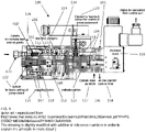
- the Alpha Lubricator 100 comprises a metal housing 101 in which a plurality of injection plungers 119 are arranged one a circle and driven synchronous in common by a hydraulic driven actuator piston 123. Each injection plunger 119 is arranged slidingly in a dosing channel 115 receiving lubricant from an internal volume 114 of the housing 101 through an inlet aperture 113.
- the inlet aperture 113 is closed by the injection plunger 119 during forward motion of the injection plunger 119 so that further forward motion by the injection plunger 119 pressurizes the received lubricant in the remaining part of the dosing channel 115 and pumps it through a non-return valve 102 into a pipe 103 and to one of the injectors of a single cylinder.
- the injection plunger 119 is retracted, and vacuum created in the dosing channel 115, until the forward end of the injection plunger 119 is retracted past the inlet aperture 113 and lubricant can flow through the inlet aperture 113 and refill the dosing channel 115.
- the volume of lubricant pressurized by the injection plunger 119 in the dosing channel 115 and expelled through the non-return valve 102 is defined by the travel distance of the injection plunger 119 from the inlet aperture 113 to the most forward position before retraction.
- the actuator piston 123 over the stroke length, the first part of the movement of the injection plunger 119 past the inlet aperture 113, and only once the injection plunger 119 has moved past the inlet aperture 113 and closed it, the lubricant is pressurised and expelled from the remaining dosing channel distance.
- the hydraulic driven actuator piston 123 is moving over an adjustable distance between its stationary rearward end stop 104 and a forward end stop 105 that is adjustable by an adjusting screw. For turning the adjusting screw 121, it is accessible at an end cap 106 that covers a flange 107 of the housing 101, through which the adjusting screw 121 extends.
- the flange 107 in the Alpha Lubricator 100 supports the spacer 122 and contains a threading 110 for adjustment of the adjusting screw 121.
- the reciprocal actuator piston 123 is driven by oscillating oil pressure in the volume 108 behind the actuator piston 123, where a solenoid valve 116 shifts between two pressure levels in this volume 108 behind the actuator piston 123. Once, the lower pressure level is reached, a spring 109 load presses the actuator piston 123 back to the rear end stop.
- the solenoid valve 116 is regulated by corresponding signals from a control unit.
- a spacer 122 for basic settings of the pump stroke is provided in the 107 flange behind the end cap 106, at which the head of the adjusting screw 121 is accessible for adjustment by rotation.
- the Alpha Lubricator is different relatively the above mentioned patents DE19743955B4 and DK173288B1 in that a capacitive feedback sensor 120 is used to verify a sufficiently long stroke length of the hydraulic actuator.
- This feedback sensor 120 is also illustrated in FIG 1 .
- the hydraulic actuator piston comprises two circumferential grooves 111, and the feedback sensor 120 gives a confirmation signal of proper lubrication to the central controller if the stroke of the hydraulic actuator piston 123 is long enough for the second groove 111 to move pass the feedback sensor 120.
- the feedback sensor 120 creates a double-pulsed signal which the central controller takes as confirmation of proper lubrication. If only one the first groove 111 passes by the feedback sensor 120, the corresponding single-pulsed signal from the feedback sensor 120 indicates to the central controller general functioning of the feedback sensor 120 and movement of the actuator piston 123 over at least a small distance but not sufficient movement of the actuator piston 123 for proper lubrication. If the feedback sensor 120 is giving any signal, a warning message is provided by the controller that the stroke was not measured as long enough for proper lubrication.
- the non-return valve 102 is provided inside a valve-chamber 102' and is build up traditionally by comprising a valve-member, in this case a spherical valve-member, pre-stressed against a valve-seat by a spring.
- the lubricant in the dosing channel 115 displaces the spherical valve-member against the pre-stressing force of the helical spring once the lubricant pressure rises above a predetermined limit where the force created by the pressurised lubricant is above the pre-stressed force.
- the non-return valve 102 gives passage to the pipe 103 for lubricant flow to the injector as long as the pressure is at the increased state in the injection phase.
- the non-return valve 102 closes again for the idle phase and stays closed until the next injection phase.
- Ball valves are in general mentioned in US3387625 , US2005/217730 and WO2015192808 .
- the Korean patent application KR20160124961 by Jinhap Ind Co Ltd discloses a method of deformation of a check valve by pressing a steel ball into the valve seat.
- the check valve has a special structure of a two regions that have different bending radii. This special structure results is believed to result in the check valve getting leaks with time.
- the circular edge between the two regions is deformed by pressing a ball into the valve seat so that a smooth gradual transition is created instead of a sharp line between the two regions.
- Such type of valve seat as in KR20160124961 is not found in the Alpha-type lubricator and a deformation of a transition line between two curved regions with different bending radii does not appear to apply for the problem that has been experienced with the Alpha-type lubricator.
- a particular objective is to provide a method for improving a lubrication system with a lubricator of the type as described above, especially an Alpha lubrication system with an Alpha Lubricator.
- the objective is obtained with a method mentioned by way of introduction and which is peculiar in that the method comprises removing the spring and valve member from the valve chamber and modifying the valve-seat in the valve-chamber by forcing a deformation member into the valve-seat and causing plastic deformation of the valve-seat for improving dimensional precision of the valve seat by the deformation member; re-fitting the valve member and the spring after modification of the valve-seat; subsequently operating the lubricator for the lubrication system of the engine with the modified valve-seat.
- lubricator is used herein for a lubricator pump unit that pressurizes and doses the lubricant for the lubricant injectors in the corresponding large slow-running two-stroke engine, typically fuelled with diesel or gas fuel.
- the lubricator and its function are explained in detail below with reference to the Alpha Lubricator as an example, which was described above with reference to FIG. 1 .
- injection phase is used for the time during which lubricant is injected into the cylinder by an injector.
- injection-cycle is used for the time it takes to start an injection sequence and until the next injection sequence starts, an injection sequence typically involving all lubricant injectors in each injection sequence.
- the injection sequence comprises a single injection by each injector, in which case the injection-cycle is measured from the start of the injection phase to the start of the next injection phase.
- timing of the injection is used for the adjustment of the start of the injection phase by the injector relatively to a specific position of the piston inside the cylinder.
- the end points are optionally included.
- This objective was achieved by modifying the valve-seat in the valve chamber by forcing, for example pressing or hammering, a deformation-member into the valve seat at a force causing plastic deformation thereof.
- the deformation member has a cross section that is larger than the lateral extension of the valve seat and is pressed onto the valve seat with sufficient force or hammered into the valve seat with sufficient force and speed to cause the plastic deformation.
- the exact force and optional speed necessary to cause such deformation depends on the size and type of metal of the valve seat.
- the term "sufficient force” implies that a deformation is achieved in that metal is moved on the surface of the valve seat due to the pressure and impact on its surface.
- This reduction of surface roughness has surprisingly turned out not only to provide a closer and tighter contact between the valve member and the valve seat but also to result in a many-fold increase of the lifetime of the non-return valve, and thus increases the lifetime of the lubricator and improves the entire lubrication system.
- the surface roughness is in the range of 12.5 to 0.8 ⁇ m, 16.3 to 0.8 ⁇ m, or 1.6 to 0.8 ⁇ m.
- the impression of the deformation tool modifies the shape of the valve seat.
- the final shape of the valve seat depends on the shape of the deformation tool, the deformation member of which is formed as a mirror template to the deformed valve seat.
- the deformation member is convex and creates a concave surface of the valve seat.
- a useful deformation member has a spherical surface and creates a spherical impression in the valve seat such that the valve seat follows a part of a sphere.
- the deformation member is concave and creates a convex shape of the valve seat.
- An example is a convex valve seat that is shaped as a circular-symmetric torus, for example with an elliptical or circular cross section. If also the valve member is convex, for example spherical, the valve member and the toroidal valve seat have a mutual ring of contact which is very narrow due to the tangential contact. A narrow ring of contact is also obtained between such torus and a conical valve member.
- valve member After modification, a valve member is loaded into the valve chamber for tightening against the valve seat along a circular ring after modification of the valve seat.
- the method comprises modifying to the valve seat to attain a concave shape with a first radius of curvature, wherein the first radius of curvature is measured in a plane that is orthogonal to the valve seat.
- orthogonal to the valve seat is to be understood as orthogonal to the plane containing the ring of contact between the valve seat and the valve member.
- the deformation member has a first radius of curvature that is not less than a second radius of curvature of a convex valve member, typically ball member, which is closing the valve by being pre-stressed against the valve seat.
- valve member is the same as the one that was inside the valve chamber prior to modification.
- a new valve member is loaded, for example having a different size and or shape.
- a typical valve member is of spherical shape so that the valve is a non-return ball valve.
- valve member is made of metal, for example steel.
- valve member is made of polymer or ceramics.
- the radius of curvature for the valve seat is the same or approximately the same as the valve member. In other embodiments, the radius of curvature for the valve seat is larger, for example within 5-50% larger, than the radius of curvature of the valve member, for example ball member. In this case, the curvature of the valve seat is sufficient to guide the curved valve member to rest centrally on the valve seat. However, due the different curvatures, the ring of contact between the convex surface of the valve member and the concave surface of the valve seat is relatively thin, which is an advantage for good tightness and quick response of the non-return valve.
- the thickness of the ring-formed contact surface between the valve member and the valve seat is in the range of 0.01 to 0.5 mm, optionally in the range of 0.05 and 0.5 mm or in the range of 0.1 mm to 0.5 mm, if the valve seat has a diameter of 3 to 10 mm. In terms of an angular span in the polar angle, this corresponds roughly to 0.1 to 10 degrees. In some practical embodiments, a useful polar contact angle is in the range of 0.1 to 5 degrees.
- the contact surface between the valve member and the valve seat has an area in the range of 0.1 mm2 to 2 mm2.
- the valve member is 30-100% larger than the inner diameter of the valve seat.
- the ball member is in the range of 4-6 mm in diameter.
- the inner diameter of the valve seat is approximately equal to the diameter of the conduit which is upstream of the valve seat and closed by the non-return valve.
- valve seat and the valve member having the same radius of curvature also allows other concave shapes for the valve seat, for example ellipsoidal, parabolic, or hyperbolic. It is even possible to use a conical shape.
- the valve seat is circular symmetric.
- the circular symmetry varies by less than 0.2 mm, for example less than 0.1 mm, when measured across the valve seat.
- the valve-seat in the valve-chamber is modified from a non-spherical shape into a shape that is part-spherical.
- the part-spherical valve-seat resembles the surface of a spherical segment, also called a spherical frustum.
- a valve-seat with such shape is called a part-spherical valve-seat.
- the modification of the lubricator comprises modifying the valve-seat into the part-spherical shape by forcing, for example pressing or hammering, a deformation-member with a spherical, hemispherical, or part-spherical surface into the valve-seat at a force that causes plastic deformation of the valve-seat from a non-spherical shape into a part-spherical shape.
- the modified valve-seat in the valve-chamber has a shape that is part-spherical with a bending radius equal to or substantially equal to but not smaller than a bending radius of the valve-member that is abutting the valve-seat.
- the radius of curvature of the valve seat after deformation is larger than the radius of curvature of the valve member that is inserted after deformation.
- a further non-return valve is added to the existing non-return valve such that a double valve system is provided.
- a double valve system improves the tightness and longevity of the system.
- a further non-return valve is added in series to the modified non-return valve. Such additional non-return valve is potentially attached to the lubricator housing at the lubricant exit.
- the modified Alpha-type lubricator turned out to have a much longer lifetime in that no leak was detected even after 2 million injection cycles.
- the final technical solution was a simple modification of the existing Alpha Lubricator at relatively low cost, nevertheless solving the short-life problem of the entire Alpha lubrication system. Even in still properly functioning systems, or in new Alpha Lubricators, a modification according to the above can be made to obtain an improved valve seat.
- the method comprises operating the lubricator in the lubrication system for at least 100,000 lubrication injection cycles prior to the modification, and operating the lubrication system with the lubricator and the modified non-return valve after the modification.
- the lubrication system provides lubricant to injectors for lubricating the cylinder or cylinders in a large slow-running two-stroke engine engine, for example a marine engine or a large engine in power plants.
- the engine is burning diesel or gas fuel.
- the engine comprises one or more cylinders, each with a reciprocal piston inside and with a plurality of lubricant injectors distributed along a perimeter of the cylinder for injection of lubricant into the cylinder at various positions on the perimeter during injection phases.
- the lubrication system comprises a lubricator that is pipe-connected to each injector by a lubricant feed conduit, for example one feed conduit for each injector, for providing pressurized lubricant to each injector though the lubricant feed conduit during the injection phases.
- the lubricator is of the type that comprises a housing, typically metal housing, in which a hydraulic-driven actuator piston is arranged reciprocal with a stroke length along a stroke direction.
- the lubricator further comprises a stroke length adjustment mechanism configured for variably adjusting the stroke length of the reciprocal hydraulic-driven actuator piston between a minimum stroke length and a maximum stroke length.
- the lubricator further comprises a plurality of injection plungers slidingly arranged in corresponding dosing channels, wherein the injection plungers are coupled to the actuator piston in order to be moved by the actuator piston and for pressurizing lubricant in the dosing channels during this movement.
- the injector plungers are moved over a corresponding length.
- the movement the injection plungers inside the dosing channel pressurizes the lubricant in the dosing channel while the injection plungers move over a dosing channel distance, where the dosing channel distance defines the volume of lubricant in a pumping action expelled from the dosing channel during the injection phase through a non-return valve and through the feed conduit to the injector for injection of the lubricant into the engine cylinder.
- the dosing channel distance is equal to or less than the stroke length. This depends on the configuration.
- the dosing channel distance is adjustable between a minimum dosing channel distance and a maximum dosing channel distance corresponding to the actuator piston's variable stroke length between the minimum stroke length and the maximum stroke length.
- the lubricator also comprises a valve, typically electrical valve, arranged for causing switch between hydraulic pressure levels that are acting on the actuator piston in order to hydraulically drive the actuator piston reciprocally by the switching pressure levels.
- a valve typically electrical valve, arranged for causing switch between hydraulic pressure levels that are acting on the actuator piston in order to hydraulically drive the actuator piston reciprocally by the switching pressure levels.
- the actuator piston is pre-stressed against the rear end stop by a helical spring.
- the lubricator receives high pressure oil for driving the actuator piston, and the valve switches between
- the lubrication system further comprises a controller that controls the switching of the valve.
- the controller is electrically connected to the electrical valve for controlling the timing of the switching for the injection phases by corresponding electrical signals transmitted from the controller to the electrical valve.
- the controller operates a high pressure valve upstream of the lubricator in order to provide switching of the high pressure oil for driving the actuator piston.
- the lubrication system is improved by modifying the non-return valve of the lubricator such that the valve-seat, typically metal valve seat, in the valve-chamber is improved, typically after a certain time of operation, but possibly also prior to start of operation while the lubricator is still new.
- the final technical solution turned out to be a simple modification of existing lubricators at relatively low cost, nevertheless solving the short-life problem of lubrication systems.
- injector is used for an injection valve system comprising an injector housing having a lubricant inlet port, flow-connected to the lubricant feed conduit for receiving lubricant from it for injection into the cylinder.
- the injector further comprises one single injection nozzle with a nozzle aperture as a lubricant outlet that extends into the cylinder for injecting lubricant from the inlet port into the cylinder in the injection phase.
- the injector has a single nozzle that extends into the cylinder through the cylinder wall, when the injector is properly mounted, the nozzle itself, optionally, has more than a single aperture.
- nozzles with multiple apertures are disclosed in WO2012/126480 .
- each of the injectors comprises an outlet-valve system at the nozzle configured for opening for flow of lubricant to the nozzle aperture during an injection phase upon pressure rise above a predetermined limit at the outlet-valve system and for closing the outlet-valve system after the injection phase.
- the outlet-valve system closes off for back-pressure from the cylinder and also prevents lubricant to enter the cylinder unless the outlet-valve is open.
- the outlet-valve system comprises an outlet non-return valve.
- the outlet-valve-member for example a ball, ellipsoid, plate, or cylinder, is pre-stressed against an outlet-valve-seat by an outlet-valve spring.
- the pre-stressed force of the spring is counteracted by the lubricant pressure, and if the pressure is higher than the spring force, the outlet-valve-member is displaced from its outlet-valve-seat, and the outlet non-return valve opens for injection of lubricant through the nozzle aperture into the cylinder.
- the outlet-valve spring acts on the valve-member in a direction away from the nozzle aperture, although, an opposite movement is also possible.
- the central controller comprises a computer or is connected by an electronic wired or wireless connection to a computer, where the computer is of the type that is configured for monitoring parameters for the actual state and motion of the engine, such that the amount and timing of the lubricant injection is controlled on the basis of the parameters.
- the injectors are SIP injectors configured to provide a mist of lubricant into the scavenging air of the cylinders.
- a spray of atomized droplets also called mist of oil, is important in SIP lubrication, where the sprays of lubricant are repeatedly injected by the injectors into the scavenging air inside the cylinder prior to the piston passing the injectors in its movement towards the TDC.
- the atomized droplets are diffused and distributed onto the cylinder wall, as they are transported in a direction towards the TDC due to a swirling motion of the scavenging air towards the TDC.
- the injectors comprise a nozzle with a nozzle aperture of between 0.1 and 1 mm, for example between 0.2 and 0.5mm, and are configured for ejecting a spray of atomized droplets, which is also called a mist of oil.
- the atomization of the spray is due to highly pressurized lubricant in the lubricant injector at the nozzle.
- the pressure from the lubricator is higher than 10 bar, typically between 20 bar and 120 bar for this high pressure injection.
- An example is an interval of between 30 and 100 bar.
- Another example is an interval of between 60 and 120 bar, for example between 60 and 100 bar.
- the injection time is short, typically in the order of 5-30 milliseconds (msec). However, the injection time can be adjusted to 1 msec or even less than 1 msec, for example down to 0.1 msec.
- the lubricator is operated with the correspondingly necessary parameters, especially the pressure intervals.
- the method comprises operating the lubrication system with the modified lubricator at a lubricant pressure in the range of 20-100 bar in combination with SIP injectors, injection a mist of atomized droplets of lubricant by the SIP injectors into swirling scavenging air inside the engine cylinder and distributing the droplets onto the cylinder wall during transport of the droplets by swirling motion towards the top dead centre, TDC, of the cylinder.
- Lubricants used in marine engines typically, have a typical kinematic viscosity of about 220 cSt at 40°C and 20 cSt at 100°C, which translates into a dynamic viscosity of between 202 and 37 mPa ⁇ s.
- An example of a useful lubricant is the high performance, marine diesel engine cylinder oil ExxonMobil ® Mobilgard TM 560VS.
- Other lubricants useful for marine engines are other Mobilgard TM oils as well as Castrol ® Cyltech oils.
- lubricants for marine engines have largely identical viscosity profiles in the range of 40-100°C and are all useful for atomization, for example when having a nozzle aperture diameter of 0.1-0.8 mm, and the lubricant has a pressure of 30-80 bar at the aperture and a temperature in the region of 30-100°C or 40-100°C. See also, the published article on this subject by Rathesan Ravendran, Peter Jensen, Jesper de Claville Christiansen, Benny Endelt, Erik Appel Jensen, (2017) "Rheological behaviour of lubrication oils used in two-stroke marine engines", Industrial Lubrication and Tribology, Vol. 69 Issue: 5, pp.750-753, https://doi.org/10.1108/ILT-03-2016-0075 .
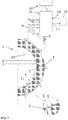
- FIG. 2 illustrates one half of a cylinder of a large slow-running two-stroke engine, for example marine diesel engine.
- the cylinder 1 comprises a cylinder liner 2 on the inner side of the cylinder wall 3. Inside the cylinder wall 3, there are provided a plurality of injectors 4 for injection of lubricant into the cylinder 1.
- the injectors 4 are distributed along a circle with the same angular distance between adjacent injectors 4, although this is not strictly necessary. Also, the arrangement along a circle is not necessary, seeing that an arrangement with axially shifted injectors is also possible, for example every second injector shifted towards the piston's top dead centre (TDC) relatively to a neighbouring injector.
- TDC top dead centre
- the injectors 4 receive pressurised lubrication oil from a lubricator 11 through lubrication supply lines 9.
- the supplied oil is typically heated to a specific temperature, for example 50-60 degrees.
- the lubricator 11 supplies pressurised lubrication oil to the injectors 4 in precisely timed pulses, synchronised with the piston motion in the cylinder 1 of the engine.
- the injection by the lubricator 11 is controlled by a controller 12.
- the controller 12 monitors parameters for the actual state and motion of the engine, including speed, load, and position of the crankshaft, as the latter reveals the position of the pistons in the cylinders.
- Each of the injectors 4 has a nozzle 5 with a nozzle aperture 5' from which lubricant is ejected under high pressure into the cylinder 1, for example in the form of a compact jet or as a fine atomized spray 8 with miniature droplets 7 for SIP injection.
- the nozzle aperture has a diameter of between 0.1 and 0.8 mm, such as between 0.2 and 0.5 mm, which at high pressure atomizes the lubricant into a fine spray 8, which is in contrast to a compact jet of lubricant.
- Pressures are above 10 bar, for example in the range 10-120 bar, optionally 20 to 120 bar or 20 to 100 bar, 30 to 80 bar, or 50 to 80 bar, or 60 to 120 bar, or even at higher pressure than 120 bar,
- the swirl 10 of the scavenging air in the cylinder 1 transports and presses the spray 8 against the cylinder liner 2 such that an even distribution of lubrication oil on the cylinder liner 2 is achieved.
- the cylinder liner 2 is provided with free outs 6 for providing adequate space for the spray 8 or jet from the injector 4.
- the lubricator 11 is connected to a supply conduit 14 for receiving lubricant from a lubricant supply 15, including an oil pump, and a return conduit 13 for return of lubricant, typically to an oil reservoir, optionally for recirculation of lubricant.
- the lubricant pressure in the supply conduit 14 is higher than the pressure in the return conduit 13, for example at least two times higher.
- the lubricant supply conduit 14 is also used for supplying lubricant for lubrication in addition to driving the actuator piston in the lubricator 11.
- FIG. 3 illustrates an example of a lubricator 11 for modification.
- the numbering is equal to the modified prior art lubricator of FIG. 1 .
- the valve-chamber 102' Prior to modification, contains the single non-return valve 102 of FIG. 1 .
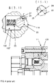
- FIG. 4 is a more detailed drawing of the non-return valve 102 in the valve-chamber 102' of prior art lubricator 11 of FIG. 1 .
- Two enlarged portions B and C illustrate details in further magnification of 3 and 6, respectively.
- the non-return valve 102 comprises a spherical valve-member 23, pre-stressed against a valve-seat 24 by the load from a helical spring 25.
- the lubricant in the dosing channel 115 displaces the valve-member 23 against the pre-stressing force of the spring 25, once the lubricant in the dosing channel 115 achieved a pressure above a predetermined limit.
- valve-seat 24 is a sharp edge, despite the valve-chamber 102' generally having a conical end-portion 27.
- Thorough study of the early mal-functioning of the lubricator 11 has revealed that leaks are due to tightness problems of the sharp edged valve-seat 24.
- valve-seat 24 is modified.
- the valve-seat after modification has a profile that is part of a sphere, optionally having the same radius as the spherical valve-member.
- FIG. 5 shows some microscope images of a valve seat of an Alpha Lubricator prior to modification.
- FIG. 5a shows pronounced roughness of the valve seat as well as metal fringes 35 in in the valve seat of a new Alpha Lubricator, which is detrimental to tightness of the non-return valve.
- FIG. 5b shows edges 34 in the valve seat 24 of a new Alpha Lubricator, which prevents a proper sealing between the valve seat 24 and the ball member.
- FIG. 5c show a micrograph of a used Alpha Lubricator, illustrating sections 24' of the valve seat appearing broader than other sections 24", which is due to elliptical shape of the valve seat. An elliptical valve seat is probably due to uneven wear during use. It does not seal properly any more against a spherical valve member. All these defects in the valve seat, some stemming from a new Alpha Lubricator, others from wear during use, prevent a satisfactory sealing, especially at elevated lubricant pressure.
- FIG. 6a and 6b show measurements of performance of a lubricator before modification, where the valve-seat 24 was sharp-edged as illustrated in FIG. 4 and defects as in FIGF. 5.
- the six graphs in FIG. 6a and FIG. 6b are made for the six outlets of the Alpha Lubricator, each outlet having one non-return valve.
- the measurements in FIG. 8a were made after 3850 injection cycles. The peaks show injections and the horizontal level shows the pressure level in the idle phase.
- the graphs in FIG. 8b show similar measurements after 1 million cycles.
- the drop of the solid drawn curves illustrates pressure loss in the idle phase, which is due to leaking non-return valves 102.
- FIG. 7 shows measurements of performance of a modified lubricator after 2 million injection cycles.
- the experimental results show horizontal pressure curves in the idle phases between the spikes of the injection phases.
- the horizontal pressure levels of FIG. 7 in contrast to the decreasing pressure curves of FIG 6b , express increased lifetime by more than a factor of 2 of the modified non-return valve 102 with respect to tightness.
- the lubricator 11 in the test experiments of FIG. 7 had a valve-seat 24 that was modified to a part-spherical configuration with smaller surface roughness and higher precision with respect to circular symmetry.
- the modification of the valve seat for the experiments of FIG. 7 has been made by pressing a deformation-member in the shape of a ball of approximately the same size as the ball-shaped valve-member 23 onto the sharp-edged valve-seat 24 with a force corresponding to 200 kg. This force was sufficient to deform the sharp-edged valve-seat 24 from the configuration of FIG. 4 into a shape of a part of a sphere with less surface roughness and more precise circular symmetry.
- Deformation by pressing or hammering a deformation member into the valve-chamber, for example a steel ball loaded with a force, is a simple way of modifying the sharp-edged valve-seat 24 of FIG. 4 .
- FIG. 8 illustrates an example in which the valve-seat 24 has been modified by deformation into concave segment, for example part-spherical segment, such as used for the test experiments of FIG. 7 . It shows a ball-shaped valve-member 23 resting against the valve seat 24.
- FIG. 9 shows a microscope image of a modified valve seat in which a deformation member has been used to deform the valve seat.
- a spherical deformation member with a surface roughness of 0.06 ⁇ m (arithmetic average roughness value Ra) was pressed into the valve seat with a force corresponding to 200 kg, caused deformation, and resulted in a changed surface roughness of 0.8 ⁇ m.
- the width of the ring-shaped valve seat was 0.06 mm.
- the surface area of the valve seat was in the order of 0.5 mm2.
- the final valve seat has a concave shape, typically part-spherical shape, for example having the same radius of curvature or substantially same radius as the spherical valve-member. Due to this part-spherical valve-seat, the contact area 28 between the spherical valve-member 23 and the valve set 24 is smoother than between the spherical valve-member 23 and the sharp-edged valve-seat 24 in FIG. 4 .
- the valve seat attains a concave form with a radius of curvature that is larger than for the valve member.
- the final valve seat has a conical shape or a convex toroidal shape.
- the radius of curvature 33 of the valve seat 24 and the radius of curvature 34 of the spherical valve-member are measured in a plane that is orthogonal and central to the valve seat.
- the two radii of curvature are illustrated in FIG. 8 , which is a cross sectional view, and thus a view onto such plane.
- FIG. 10a illustrates a tool 30 with a stem 31 and a deformation member 32 at the end of the stem 31.
- the deformation member 32 has a spherical shape, which results in a spherical deformation of the valve seat if pressed or hammered into the valve seat 24.
- FIG. 10b illustrates an ellipsoidal deformation member 32', where the longitudinal axis of the ellipsoid is parallel to the stem and, thus, circular symmetric in a plane lateral thereto.
- FIG. 10c illustrates a conical deformation member 32".
- the spherical shape of the deformation member 32 has the advantage over the conical deformation member 32" in that the circular deformation of the valve seat is not so critically dependent on a precise parallel orientation of the stem 31 with the deformation member 32, 32" relatively to the central axis of the valve seat 24.
- the spherical deformation member 32 is easiest to operate.
Landscapes
- Engineering & Computer Science (AREA)
- General Engineering & Computer Science (AREA)
- Mechanical Engineering (AREA)
- Lubrication Of Internal Combustion Engines (AREA)
- Details Of Reciprocating Pumps (AREA)
Claims (11)
- Verfahren zur Verbesserung eines Schmiersystems eines großen langsam laufenden Motors,wobei der Motor einen Zylinder (1) mit einem hin- und hergehenden Kolben im Inneren und mit einer Vielzahl von Schmiermitteleinspritzvorrichtungen (4) umfasst, die zur Einspritzung von Schmiermittel in den Zylinder (1) an verschiedenen Positionen an dem Umfang während Einspritzphasen entlang eines Umfangs des Zylinders (1) verteilt sind;wobei das Schmiersystem konfiguriert ist, um den Einspritzvorrichtungen (4) in den Einspritzphasen Schmiermittel bereitzustellen; wobei das Schmiersystem eine Schmiervorrichtung (11) umfasst, um mit jeder Einspritzvorrichtung (4) durch eine Schmiermittelzufuhrleitung (9) rohrverbunden zu sein, um jeder Einspritzvorrichtung (4) durch die Schmiermittelzufuhrleitung (9) in den Einspritzphasen unter Druck stehendes Schmiermittel bereitzustellen;wobei die Schmiervorrichtung (11) ein Gehäuse (101) umfasst, in dem ein hydraulisch angetriebener Betätigungskolben (123) hin- und hergehend entlang einer Hublänge angeordnet ist,wobei das Gehäuse (101) ferner eine Vielzahl von Einspritzkolben (119) und eine entsprechende Vielzahl von Dosierkanälen (115) sowie Rückschlagventile (102) umfasst, eines für jeden Dosierkanal (115), wobei jeder Einspritzkolben (119) verschiebbar in einem der Dosierkanäle (115) angeordnet ist, wobei die Einspritzkolben (119) an den Betätigungskolben (123) gekoppelt sind, um gemeinsam mit dem Betätigungskolben (123) über die Hublänge bewegt zu werden und als Folge Schmiermittel in den Dosierkanälen (115) über eine Dosierkanalstrecke unter Druck zu setzen, um das unter Druck gesetzte Schmiermittel aus jedem der Dosierkanäle (115) durch das entsprechende Rückschlagventil (102) zur Einspritzung des Schmiermittels in den Motorzylinder (1) auszustoßen; wobei die Dosierkanalstrecke das Volumen an Schmiermittel definiert, das aus dem Dosierkanal (115) durch das Rückschlagventil (102) während der Einspritzphase ausgestoßen wird;wobei jedes Rückschlagventil (102) in einer entsprechenden Ventilkammer (102') in dem Gehäuse (11) bereitgestellt ist und ein Ventilelement (23) umfasst, das durch die Last einer Feder (25) gegen einen Ventilsitz (24) vorgespannt ist;dadurch gekennzeichnet, dass das Verfahren das Entfernen der Feder (25) und des Ventilelements (23) aus der Ventilkammer (102') und das Modifizieren des Ventilsitzes (24) in der Ventilkammer (102') durch Zwingen eines Verformungselements (32, 32', 32") in den Ventilsitz (24) und Bewirken von plastischer Verformung des Ventilsitzes (24) zur Verbesserung von dimensionaler Präzision des Ventilsitzes durch das Verformungselement (32, 32', 32''); Wiedereinbauen des Ventilelements und der Feder nach Modifikation des Ventilsitzes; anschließend Betätigen der Schmiervorrichtung (11) für das Schmiersystem des Motors mit dem modifizierten Ventilsitz (24) umfasst.
- Verfahren nach Anspruch 1, wobei die Modifikation das Bereitstellen eines kreissymmetrischen Verformungselements (32, 32', 32'') und das Verformen des Ventilsitzes in eine kreissymmetrische Form durch Zwingen des Verformungselements (32, 32', 32") in den Ventilsitz (24) umfasst.
- Verfahren nach Anspruch 2, wobei die Kreissymmetrie um weniger als 0,2 mm variiert, wenn über den Ventilsitz (24) gemessen.
- Verfahren nach einem vorhergehenden Anspruch, wobei das Verfahren das Bereitstellen eines Verformungselements (32, 32', 32") mit einer Oberflächenrauigkeit umfasst, die kleiner als die Oberflächenrauigkeit des Ventilsitzes (24) ist; und wobei die Verformung das Zwingen des Verformungselements (32, 32', 32") in den Ventilsitz (24) mit einer Kraft umfasst, die Reduzierung der Oberflächenrauigkeit des Ventilsitzes (24) für engen Kontakt zwischen dem Ventilelement (23) und dem Ventilsatz (24) bewirkt.
- Verfahren nach Anspruch 4, wobei das Verfahren das Reduzieren der Oberflächenrauigkeit des Ventilsitzes (24) auf weniger als 12,5 pm durch die Verformung mit dem Verformungselement (32, 32', 32'') umfasst.
- Verfahren nach Anspruch 2 oder 3, wobei das Verformungselement (32, 32', 32'') entweder A oder B ist, wobeiA) das Verformungselement (32, 32') konvex mit einem ersten Krümmungsradius ist und das Verfahren das Modifizieren zu dem Ventilsitz (24) umfasst, um diesen ersten Krümmungsradius (34) zu erreichen, wobei der erste Krümmungsradius (34) in einer Ebene orthogonal zu dem Ventilsitz (24) gemessen wird; wobei das Verfahren das Laden eines Ventilelements (23) in die Ventilkammer (102') zum Festziehen gegen den Ventilsitz (24) entlang eines kreisförmigen Rings nach Modifikation des Ventilsitzes (24) umfasst, wobei das Ventilelement (23) mit einem zweiten Krümmungsradius (33) bereitgestellt ist, der gleich dem oder kleiner als der erste Krümmungsradius (34) ist, wenn in einer Ebene orthogonal zu dem Ventilsitz (24) gemessen;B) das Verformungselement (32") konisch ist und das Verfahren das Modifizieren des Ventilsitzes (24) umfasst, um diese konische Form zu erreichen.
- Verfahren nach Anspruch 6, wobei der erste Krümmungsradius 5-50 % größer als der zweite Krümmungsradius ist.
- Verfahren nach einem vorhergehenden Anspruch, wobei die Modifikation Verformung des Ventilsitzes (23) in eine teilweise kugelförmige Form umfasst, indem ein kugelförmiges Verformungselement (32) bei einer Kraft in den Ventilsitz (23) gezwungen wird, die mechanische Verformung des Ventilsitzes (23) von einer nicht kugelförmigen Form in eine teilweise kugelförmige Form verursacht.
- Verfahren nach einem der vorhergehenden Ansprüche, wobei das Verfahren das Betätigen der Schmiervorrichtung (11) in dem Schmiersystem für zumindest 100.000 Schmiereinspritzzyklen vor der Modifikation und das Fortsetzen der Betätigung des Schmiersystems mit der Schmiervorrichtung (11) und dem modifizierten Ventilsitz (24) nach der Modifikation umfasst.
- Verfahren nach einem vorhergehenden Anspruch, wobei das Verfahren das Betätigen des Schmiersystems durch Zuführen von Schmiermittel zu den Einspritzvorrichtungen mit der modifizierten Schmiervorrichtung (11) bei einem Schmiermitteldruck in dem Bereich von 20-100 bar und das Einspritzen eines Nebels aus zerstäubten Schmiermitteltröpfchen durch die Einspritzvorrichtungen in wirbelnde Spülluft innerhalb des Motorzylinders und Verteilen der Tröpfchen auf der Zylinderwand während Transport der Tröpfchen durch Wirbelbewegung in Richtung des oberen Totpunkts, TDC, des Zylinders umfasst.
- Verfahren nach einem vorhergehenden Anspruch, wobei das Verfahren das Betätigen des Schmiersystems mit der Schmiervorrichtung (11) und dem modifizierten Ventilsitz (24) nach der Modifikation bei einem Schmiermitteldruck in dem Bereich von 20-100 bar in Kombination mit SIP-Einspritzvorrichtungen, Einspritzen eines Nebels aus zerstäubten Schmiermitteltröpfchen durch die SIP-Einspritzvorrichtungen in wirbelnde Spülluft innerhalb des Motorzylinders und Verteilen der Tröpfchen auf der Zylinderwand während Transport der Tröpfchen durch Wirbelbewegung in Richtung des oberen Totpunkts, TDC, des Zylinders umfasst.
Applications Claiming Priority (2)
| Application Number | Priority Date | Filing Date | Title |
|---|---|---|---|
| DKPA201870647A DK180400B1 (en) | 2018-10-02 | 2018-10-02 | Deformation of a valve seat for improving a lubricator pump unit and lubrication system of a large slow-running two-stroke engine |
| PCT/DK2019/050288 WO2020069705A1 (en) | 2018-10-02 | 2019-10-01 | Deformation of a valve seat for improving a lubricator pump unit and lubrication system of a large slow-running two-stroke engine, and an improved lubricator pump unit |
Publications (2)
| Publication Number | Publication Date |
|---|---|
| EP3861199A1 EP3861199A1 (de) | 2021-08-11 |
| EP3861199B1 true EP3861199B1 (de) | 2022-12-07 |
Family
ID=68165411
Family Applications (1)
| Application Number | Title | Priority Date | Filing Date |
|---|---|---|---|
| EP19783421.1A Active EP3861199B1 (de) | 2018-10-02 | 2019-10-01 | Deformation eines ventilsitzes zur verbesserung einer schmierölpumpeneinheit und schmiersystem eines grossen langsam laufenden zweitaktmotors |
Country Status (7)
| Country | Link |
|---|---|
| EP (1) | EP3861199B1 (de) |
| JP (1) | JP7474247B2 (de) |
| KR (1) | KR102788766B1 (de) |
| CN (1) | CN112955634B (de) |
| DK (2) | DK180400B1 (de) |
| SG (1) | SG11202103155WA (de) |
| WO (1) | WO2020069705A1 (de) |
Family Cites Families (29)
| Publication number | Priority date | Publication date | Assignee | Title |
|---|---|---|---|---|
| GB608510A (en) * | 1947-01-29 | 1948-09-16 | William Richard Penney | Improvements in valve seats |
| US3387625A (en) | 1965-06-24 | 1968-06-11 | W L Molding Company | Check valve |
| US3589386A (en) * | 1969-09-02 | 1971-06-29 | Air Con Inc | Pilot valve |
| US3894556A (en) * | 1974-01-02 | 1975-07-15 | Lear Siegler Inc | Pressure limiting valve |
| ZA792240B (en) * | 1978-05-26 | 1980-08-27 | Brock Equipment Co | A twospeed pump assembly |
| JPS5846275A (ja) * | 1981-09-14 | 1983-03-17 | Hitachi Ltd | 逆止弁 |
| JPS62187310U (de) * | 1986-05-20 | 1987-11-28 | ||
| JPH0438852Y2 (de) * | 1987-12-15 | 1992-09-10 | ||
| DE9210041U1 (de) * | 1992-07-25 | 1992-10-01 | Wolter, Hans, 8941 Sontheim | Kugelrückschlagventil |
| DE19545333A1 (de) * | 1995-12-05 | 1997-06-12 | Bosch Gmbh Robert | Ventilschließkörper und Verfahren und Vorrichtung zur Herstellung von Dichtsitzen an Ventilschließkörpern |
| JP3552849B2 (ja) * | 1996-07-12 | 2004-08-11 | 株式会社東芝 | 制御棒駆動機構の水圧駆動システムおよびその運用方法 |
| DK173288B1 (da) * | 1996-10-11 | 2000-06-13 | Man B & W Diesel As | Cylindersmøreenhed til en flercylindret forbrændingsmotor, og fremgangsmåde til styring af leveringsmængden fra en cylinder |
| US6098958A (en) * | 1998-05-06 | 2000-08-08 | Ernst Thielenhaus Kg | Valve assembly, especially for a fuel-injection valve and method of making same |
| JP2001009645A (ja) * | 1999-06-29 | 2001-01-16 | Showa Corp | スチールボールの組み付け装置 |
| US6240947B1 (en) * | 1999-08-24 | 2001-06-05 | Alliedsignal Truck Brake Systems Company | Solenoid valve seat and method of making same |
| FR2799523B1 (fr) * | 1999-10-08 | 2001-12-21 | Framatome Sa | Procede et dispositif de reparation in-situ d'un siege d'une soupape |
| JP2002340205A (ja) * | 2001-05-15 | 2002-11-27 | Denso Corp | 弁座の加工方法およびその加工方法で製造された弁座を有する弁装置 |
| JP2005201303A (ja) * | 2004-01-13 | 2005-07-28 | Toyota Industries Corp | 弁装置の製造方法 |
| US7311118B2 (en) | 2004-03-30 | 2007-12-25 | Parker-Hannifin Corporation | Floating ball check valve |
| JP2006242019A (ja) * | 2005-03-01 | 2006-09-14 | Jtekt Corp | 燃料ポンプ用チェック弁 |
| DK177258B1 (da) | 2011-03-18 | 2012-08-27 | Hans Jensen Lubricators As | Doseringssystem for cylindersmøreolie til store cylindre samt fremgangsmåde til dosering af cylindersmøreolie til store cylindre |
| DK177242B1 (da) | 2011-03-22 | 2012-08-06 | Hans Jensen Lubricators As | Injektor, doseringssystem samt fremgangsmåde til indsprøjtning af cylindersmøreolie i store cylindre i en dieselmotor |
| CN202266710U (zh) * | 2011-09-30 | 2012-06-06 | 郑州人造金刚石及制品工程技术研究中心有限公司 | 一种单向阀 |
| US9079281B2 (en) * | 2012-03-29 | 2015-07-14 | North American Fuel Systems Remanufacturing, LLC | Common rail valve seat refurbishing |
| DK177669B1 (da) | 2012-09-25 | 2014-02-10 | Hans Jensen Lubricators As | Injektionsdyse til brug ved olieinjicering af olie for smøring af cylindre i større motorer samt anvendelse heraf |
| DE102013210760A1 (de) * | 2013-06-10 | 2014-12-11 | Robert Bosch Gmbh | Kraftstoff-Hochdruckpumpe für ein Kraftstoffsystem für eine Brennkraftmaschine |
| WO2015192808A1 (zh) * | 2014-06-19 | 2015-12-23 | 广东华液动力科技有限公司 | 阀副结构、单向阀、充液阀以及溢流阀 |
| DK178164B3 (en) * | 2014-07-29 | 2024-11-20 | Hans Jensen Lubricators As | A method for lubricating large slow running two-stroke diesel engines |
| KR20160124961A (ko) * | 2015-04-20 | 2016-10-31 | (주)진합 | 체크밸브용 단조가공 시트 |
-
2018
- 2018-10-02 DK DKPA201870647A patent/DK180400B1/en not_active IP Right Cessation
-
2019
- 2019-10-01 DK DK19783421.1T patent/DK3861199T3/da active
- 2019-10-01 JP JP2021518501A patent/JP7474247B2/ja active Active
- 2019-10-01 SG SG11202103155WA patent/SG11202103155WA/en unknown
- 2019-10-01 KR KR1020217011861A patent/KR102788766B1/ko active Active
- 2019-10-01 CN CN201980070427.XA patent/CN112955634B/zh active Active
- 2019-10-01 EP EP19783421.1A patent/EP3861199B1/de active Active
- 2019-10-01 WO PCT/DK2019/050288 patent/WO2020069705A1/en not_active Ceased
Also Published As
| Publication number | Publication date |
|---|---|
| CN112955634A (zh) | 2021-06-11 |
| JP2022504200A (ja) | 2022-01-13 |
| DK3861199T3 (en) | 2023-03-06 |
| CN112955634B (zh) | 2023-05-30 |
| WO2020069705A1 (en) | 2020-04-09 |
| EP3861199A1 (de) | 2021-08-11 |
| SG11202103155WA (en) | 2021-04-29 |
| KR20210068058A (ko) | 2021-06-08 |
| KR102788766B1 (ko) | 2025-03-28 |
| DK180400B1 (en) | 2021-03-30 |
| DK201870647A1 (en) | 2020-04-28 |
| JP7474247B2 (ja) | 2024-04-24 |
Similar Documents
| Publication | Publication Date | Title |
|---|---|---|
| JP2025032109A (ja) | 大型低速2ストローク機関のルブリケータポンプユニット及び潤滑系統を改良するためのバルブシートの変更形態、ならびに改良されたルブリケータポンプユニット | |
| EP3368751B1 (de) | Grosser langsam laufender zweitaktmotor mit sip-schmierinjektor | |
| EP3861201B1 (de) | Ersatz eines ventilsitzes zur verbesserung einer schmierpumpeneinheit und schmiersystem eines grossen langsam laufenden zweitaktmotors und eine verbesserte schmierpumpeneinheit | |
| DK180400B1 (en) | Deformation of a valve seat for improving a lubricator pump unit and lubrication system of a large slow-running two-stroke engine | |
| EP3818255B1 (de) | Verfahren zur optimierung der schmierung in einem grossen, langsam laufenden zweitaktmotor | |
| EP3818256B1 (de) | Verfahren zum nachrüsten eines schmiersystems in einem grossen, langsam laufenden zweitaktmotor | |
| RU2493418C2 (ru) | Способ управления подачей топлива и устройство управления подачей топлива | |
| JPH0445670B2 (de) | ||
| JP2022504200A5 (de) |
Legal Events
| Date | Code | Title | Description |
|---|---|---|---|
| STAA | Information on the status of an ep patent application or granted ep patent |
Free format text: STATUS: UNKNOWN |
|
| STAA | Information on the status of an ep patent application or granted ep patent |
Free format text: STATUS: THE INTERNATIONAL PUBLICATION HAS BEEN MADE |
|
| PUAI | Public reference made under article 153(3) epc to a published international application that has entered the european phase |
Free format text: ORIGINAL CODE: 0009012 |
|
| STAA | Information on the status of an ep patent application or granted ep patent |
Free format text: STATUS: REQUEST FOR EXAMINATION WAS MADE |
|
| 17P | Request for examination filed |
Effective date: 20210428 |
|
| AK | Designated contracting states |
Kind code of ref document: A1 Designated state(s): AL AT BE BG CH CY CZ DE DK EE ES FI FR GB GR HR HU IE IS IT LI LT LU LV MC MK MT NL NO PL PT RO RS SE SI SK SM TR |
|
| DAV | Request for validation of the european patent (deleted) | ||
| DAX | Request for extension of the european patent (deleted) | ||
| GRAP | Despatch of communication of intention to grant a patent |
Free format text: ORIGINAL CODE: EPIDOSNIGR1 |
|
| STAA | Information on the status of an ep patent application or granted ep patent |
Free format text: STATUS: GRANT OF PATENT IS INTENDED |
|
| INTG | Intention to grant announced |
Effective date: 20220608 |
|
| GRAS | Grant fee paid |
Free format text: ORIGINAL CODE: EPIDOSNIGR3 |
|
| GRAA | (expected) grant |
Free format text: ORIGINAL CODE: 0009210 |
|
| STAA | Information on the status of an ep patent application or granted ep patent |
Free format text: STATUS: THE PATENT HAS BEEN GRANTED |
|
| AK | Designated contracting states |
Kind code of ref document: B1 Designated state(s): AL AT BE BG CH CY CZ DE DK EE ES FI FR GB GR HR HU IE IS IT LI LT LU LV MC MK MT NL NO PL PT RO RS SE SI SK SM TR |
|
| REG | Reference to a national code |
Ref country code: GB Ref legal event code: FG4D |
|
| REG | Reference to a national code |
Ref country code: CH Ref legal event code: EP Ref country code: AT Ref legal event code: REF Ref document number: 1536435 Country of ref document: AT Kind code of ref document: T Effective date: 20221215 |
|
| REG | Reference to a national code |
Ref country code: DE Ref legal event code: R096 Ref document number: 602019022925 Country of ref document: DE |
|
| REG | Reference to a national code |
Ref country code: IE Ref legal event code: FG4D |
|
| REG | Reference to a national code |
Ref country code: DK Ref legal event code: T3 Effective date: 20230301 |
|
| REG | Reference to a national code |
Ref country code: LT Ref legal event code: MG9D |
|
| REG | Reference to a national code |
Ref country code: NL Ref legal event code: MP Effective date: 20221207 |
|
| REG | Reference to a national code |
Ref country code: NO Ref legal event code: T2 Effective date: 20221207 |
|
| PG25 | Lapsed in a contracting state [announced via postgrant information from national office to epo] |
Ref country code: SE Free format text: LAPSE BECAUSE OF FAILURE TO SUBMIT A TRANSLATION OF THE DESCRIPTION OR TO PAY THE FEE WITHIN THE PRESCRIBED TIME-LIMIT Effective date: 20221207 Ref country code: LT Free format text: LAPSE BECAUSE OF FAILURE TO SUBMIT A TRANSLATION OF THE DESCRIPTION OR TO PAY THE FEE WITHIN THE PRESCRIBED TIME-LIMIT Effective date: 20221207 Ref country code: FI Free format text: LAPSE BECAUSE OF FAILURE TO SUBMIT A TRANSLATION OF THE DESCRIPTION OR TO PAY THE FEE WITHIN THE PRESCRIBED TIME-LIMIT Effective date: 20221207 Ref country code: ES Free format text: LAPSE BECAUSE OF FAILURE TO SUBMIT A TRANSLATION OF THE DESCRIPTION OR TO PAY THE FEE WITHIN THE PRESCRIBED TIME-LIMIT Effective date: 20221207 |
|
| REG | Reference to a national code |
Ref country code: GR Ref legal event code: EP Ref document number: 20230400376 Country of ref document: GR Effective date: 20230410 |
|
| REG | Reference to a national code |
Ref country code: AT Ref legal event code: MK05 Ref document number: 1536435 Country of ref document: AT Kind code of ref document: T Effective date: 20221207 |
|
| PG25 | Lapsed in a contracting state [announced via postgrant information from national office to epo] |
Ref country code: RS Free format text: LAPSE BECAUSE OF FAILURE TO SUBMIT A TRANSLATION OF THE DESCRIPTION OR TO PAY THE FEE WITHIN THE PRESCRIBED TIME-LIMIT Effective date: 20221207 Ref country code: PL Free format text: LAPSE BECAUSE OF FAILURE TO SUBMIT A TRANSLATION OF THE DESCRIPTION OR TO PAY THE FEE WITHIN THE PRESCRIBED TIME-LIMIT Effective date: 20221207 Ref country code: LV Free format text: LAPSE BECAUSE OF FAILURE TO SUBMIT A TRANSLATION OF THE DESCRIPTION OR TO PAY THE FEE WITHIN THE PRESCRIBED TIME-LIMIT Effective date: 20221207 Ref country code: HR Free format text: LAPSE BECAUSE OF FAILURE TO SUBMIT A TRANSLATION OF THE DESCRIPTION OR TO PAY THE FEE WITHIN THE PRESCRIBED TIME-LIMIT Effective date: 20221207 |
|
| P01 | Opt-out of the competence of the unified patent court (upc) registered |
Effective date: 20230509 |
|
| PG25 | Lapsed in a contracting state [announced via postgrant information from national office to epo] |
Ref country code: NL Free format text: LAPSE BECAUSE OF FAILURE TO SUBMIT A TRANSLATION OF THE DESCRIPTION OR TO PAY THE FEE WITHIN THE PRESCRIBED TIME-LIMIT Effective date: 20221207 |
|
| PG25 | Lapsed in a contracting state [announced via postgrant information from national office to epo] |
Ref country code: SM Free format text: LAPSE BECAUSE OF FAILURE TO SUBMIT A TRANSLATION OF THE DESCRIPTION OR TO PAY THE FEE WITHIN THE PRESCRIBED TIME-LIMIT Effective date: 20221207 Ref country code: RO Free format text: LAPSE BECAUSE OF FAILURE TO SUBMIT A TRANSLATION OF THE DESCRIPTION OR TO PAY THE FEE WITHIN THE PRESCRIBED TIME-LIMIT Effective date: 20221207 Ref country code: PT Free format text: LAPSE BECAUSE OF FAILURE TO SUBMIT A TRANSLATION OF THE DESCRIPTION OR TO PAY THE FEE WITHIN THE PRESCRIBED TIME-LIMIT Effective date: 20230410 Ref country code: EE Free format text: LAPSE BECAUSE OF FAILURE TO SUBMIT A TRANSLATION OF THE DESCRIPTION OR TO PAY THE FEE WITHIN THE PRESCRIBED TIME-LIMIT Effective date: 20221207 Ref country code: CZ Free format text: LAPSE BECAUSE OF FAILURE TO SUBMIT A TRANSLATION OF THE DESCRIPTION OR TO PAY THE FEE WITHIN THE PRESCRIBED TIME-LIMIT Effective date: 20221207 Ref country code: AT Free format text: LAPSE BECAUSE OF FAILURE TO SUBMIT A TRANSLATION OF THE DESCRIPTION OR TO PAY THE FEE WITHIN THE PRESCRIBED TIME-LIMIT Effective date: 20221207 |
|
| PG25 | Lapsed in a contracting state [announced via postgrant information from national office to epo] |
Ref country code: SK Free format text: LAPSE BECAUSE OF FAILURE TO SUBMIT A TRANSLATION OF THE DESCRIPTION OR TO PAY THE FEE WITHIN THE PRESCRIBED TIME-LIMIT Effective date: 20221207 Ref country code: IS Free format text: LAPSE BECAUSE OF FAILURE TO SUBMIT A TRANSLATION OF THE DESCRIPTION OR TO PAY THE FEE WITHIN THE PRESCRIBED TIME-LIMIT Effective date: 20230407 Ref country code: AL Free format text: LAPSE BECAUSE OF FAILURE TO SUBMIT A TRANSLATION OF THE DESCRIPTION OR TO PAY THE FEE WITHIN THE PRESCRIBED TIME-LIMIT Effective date: 20221207 |
|
| REG | Reference to a national code |
Ref country code: DE Ref legal event code: R097 Ref document number: 602019022925 Country of ref document: DE |
|
| PLBE | No opposition filed within time limit |
Free format text: ORIGINAL CODE: 0009261 |
|
| STAA | Information on the status of an ep patent application or granted ep patent |
Free format text: STATUS: NO OPPOSITION FILED WITHIN TIME LIMIT |
|
| 26N | No opposition filed |
Effective date: 20230908 |
|
| PG25 | Lapsed in a contracting state [announced via postgrant information from national office to epo] |
Ref country code: SI Free format text: LAPSE BECAUSE OF FAILURE TO SUBMIT A TRANSLATION OF THE DESCRIPTION OR TO PAY THE FEE WITHIN THE PRESCRIBED TIME-LIMIT Effective date: 20221207 |
|
| PG25 | Lapsed in a contracting state [announced via postgrant information from national office to epo] |
Ref country code: IT Free format text: LAPSE BECAUSE OF FAILURE TO SUBMIT A TRANSLATION OF THE DESCRIPTION OR TO PAY THE FEE WITHIN THE PRESCRIBED TIME-LIMIT Effective date: 20221207 Ref country code: MC Free format text: LAPSE BECAUSE OF FAILURE TO SUBMIT A TRANSLATION OF THE DESCRIPTION OR TO PAY THE FEE WITHIN THE PRESCRIBED TIME-LIMIT Effective date: 20221207 |
|
| REG | Reference to a national code |
Ref country code: BE Ref legal event code: MM Effective date: 20231031 |
|
| PG25 | Lapsed in a contracting state [announced via postgrant information from national office to epo] |
Ref country code: LU Free format text: LAPSE BECAUSE OF NON-PAYMENT OF DUE FEES Effective date: 20231001 |
|
| GBPC | Gb: european patent ceased through non-payment of renewal fee |
Effective date: 20231001 |
|
| PG25 | Lapsed in a contracting state [announced via postgrant information from national office to epo] |
Ref country code: LU Free format text: LAPSE BECAUSE OF NON-PAYMENT OF DUE FEES Effective date: 20231001 |
|
| PG25 | Lapsed in a contracting state [announced via postgrant information from national office to epo] |
Ref country code: GB Free format text: LAPSE BECAUSE OF NON-PAYMENT OF DUE FEES Effective date: 20231001 |
|
| PG25 | Lapsed in a contracting state [announced via postgrant information from national office to epo] |
Ref country code: GB Free format text: LAPSE BECAUSE OF NON-PAYMENT OF DUE FEES Effective date: 20231001 Ref country code: FR Free format text: LAPSE BECAUSE OF NON-PAYMENT OF DUE FEES Effective date: 20231031 |
|
| PG25 | Lapsed in a contracting state [announced via postgrant information from national office to epo] |
Ref country code: BE Free format text: LAPSE BECAUSE OF NON-PAYMENT OF DUE FEES Effective date: 20231031 |
|
| PG25 | Lapsed in a contracting state [announced via postgrant information from national office to epo] |
Ref country code: IE Free format text: LAPSE BECAUSE OF NON-PAYMENT OF DUE FEES Effective date: 20231001 |
|
| PG25 | Lapsed in a contracting state [announced via postgrant information from national office to epo] |
Ref country code: IE Free format text: LAPSE BECAUSE OF NON-PAYMENT OF DUE FEES Effective date: 20231001 |
|
| PG25 | Lapsed in a contracting state [announced via postgrant information from national office to epo] |
Ref country code: BG Free format text: LAPSE BECAUSE OF FAILURE TO SUBMIT A TRANSLATION OF THE DESCRIPTION OR TO PAY THE FEE WITHIN THE PRESCRIBED TIME-LIMIT Effective date: 20221207 |
|
| PG25 | Lapsed in a contracting state [announced via postgrant information from national office to epo] |
Ref country code: BG Free format text: LAPSE BECAUSE OF FAILURE TO SUBMIT A TRANSLATION OF THE DESCRIPTION OR TO PAY THE FEE WITHIN THE PRESCRIBED TIME-LIMIT Effective date: 20221207 |
|
| PG25 | Lapsed in a contracting state [announced via postgrant information from national office to epo] |
Ref country code: CY Free format text: LAPSE BECAUSE OF FAILURE TO SUBMIT A TRANSLATION OF THE DESCRIPTION OR TO PAY THE FEE WITHIN THE PRESCRIBED TIME-LIMIT; INVALID AB INITIO Effective date: 20191001 |
|
| PG25 | Lapsed in a contracting state [announced via postgrant information from national office to epo] |
Ref country code: HU Free format text: LAPSE BECAUSE OF FAILURE TO SUBMIT A TRANSLATION OF THE DESCRIPTION OR TO PAY THE FEE WITHIN THE PRESCRIBED TIME-LIMIT; INVALID AB INITIO Effective date: 20191001 |
|
| REG | Reference to a national code |
Ref country code: CH Ref legal event code: U11 Free format text: ST27 STATUS EVENT CODE: U-0-0-U10-U11 (AS PROVIDED BY THE NATIONAL OFFICE) Effective date: 20251101 |
|
| PG25 | Lapsed in a contracting state [announced via postgrant information from national office to epo] |
Ref country code: TR Free format text: LAPSE BECAUSE OF FAILURE TO SUBMIT A TRANSLATION OF THE DESCRIPTION OR TO PAY THE FEE WITHIN THE PRESCRIBED TIME-LIMIT Effective date: 20221207 |
|
| PGFP | Annual fee paid to national office [announced via postgrant information from national office to epo] |
Ref country code: DE Payment date: 20251029 Year of fee payment: 7 |
|
| PGFP | Annual fee paid to national office [announced via postgrant information from national office to epo] |
Ref country code: NO Payment date: 20251029 Year of fee payment: 7 |
|
| PGFP | Annual fee paid to national office [announced via postgrant information from national office to epo] |
Ref country code: DK Payment date: 20251027 Year of fee payment: 7 |
|
| PGFP | Annual fee paid to national office [announced via postgrant information from national office to epo] |
Ref country code: GR Payment date: 20251029 Year of fee payment: 7 |
|
| PGFP | Annual fee paid to national office [announced via postgrant information from national office to epo] |
Ref country code: CH Payment date: 20251101 Year of fee payment: 7 |