EP3861304B1 - Füllstandssensor zur erkennung des füllstandes eines mediums - Google Patents
Füllstandssensor zur erkennung des füllstandes eines mediums Download PDFInfo
- Publication number
- EP3861304B1 EP3861304B1 EP19794654.4A EP19794654A EP3861304B1 EP 3861304 B1 EP3861304 B1 EP 3861304B1 EP 19794654 A EP19794654 A EP 19794654A EP 3861304 B1 EP3861304 B1 EP 3861304B1
- Authority
- EP
- European Patent Office
- Prior art keywords
- level
- electrodes
- detection
- portions
- electrode
- Prior art date
- Legal status (The legal status is an assumption and is not a legal conclusion. Google has not performed a legal analysis and makes no representation as to the accuracy of the status listed.)
- Active
Links
Images










Classifications
-
- G—PHYSICS
- G01—MEASURING; TESTING
- G01F—MEASURING VOLUME, VOLUME FLOW, MASS FLOW OR LIQUID LEVEL; METERING BY VOLUME
- G01F23/00—Indicating or measuring liquid level or level of fluent solid material, e.g. indicating in terms of volume or indicating by means of an alarm
- G01F23/22—Indicating or measuring liquid level or level of fluent solid material, e.g. indicating in terms of volume or indicating by means of an alarm by measuring physical variables, other than linear dimensions, pressure or weight, dependent on the level to be measured, e.g. by difference of heat transfer of steam or water
- G01F23/24—Indicating or measuring liquid level or level of fluent solid material, e.g. indicating in terms of volume or indicating by means of an alarm by measuring physical variables, other than linear dimensions, pressure or weight, dependent on the level to be measured, e.g. by difference of heat transfer of steam or water by measuring variations of resistance of resistors due to contact with conductor fluid
-
- G—PHYSICS
- G01—MEASURING; TESTING
- G01F—MEASURING VOLUME, VOLUME FLOW, MASS FLOW OR LIQUID LEVEL; METERING BY VOLUME
- G01F23/00—Indicating or measuring liquid level or level of fluent solid material, e.g. indicating in terms of volume or indicating by means of an alarm
- G01F23/22—Indicating or measuring liquid level or level of fluent solid material, e.g. indicating in terms of volume or indicating by means of an alarm by measuring physical variables, other than linear dimensions, pressure or weight, dependent on the level to be measured, e.g. by difference of heat transfer of steam or water
- G01F23/26—Indicating or measuring liquid level or level of fluent solid material, e.g. indicating in terms of volume or indicating by means of an alarm by measuring physical variables, other than linear dimensions, pressure or weight, dependent on the level to be measured, e.g. by difference of heat transfer of steam or water by measuring variations of capacity or inductance of capacitors or inductors arising from the presence of liquid or fluent solid material in the electric or electromagnetic fields
- G01F23/263—Indicating or measuring liquid level or level of fluent solid material, e.g. indicating in terms of volume or indicating by means of an alarm by measuring physical variables, other than linear dimensions, pressure or weight, dependent on the level to be measured, e.g. by difference of heat transfer of steam or water by measuring variations of capacity or inductance of capacitors or inductors arising from the presence of liquid or fluent solid material in the electric or electromagnetic fields by measuring variations in capacitance of capacitors
- G01F23/266—Indicating or measuring liquid level or level of fluent solid material, e.g. indicating in terms of volume or indicating by means of an alarm by measuring physical variables, other than linear dimensions, pressure or weight, dependent on the level to be measured, e.g. by difference of heat transfer of steam or water by measuring variations of capacity or inductance of capacitors or inductors arising from the presence of liquid or fluent solid material in the electric or electromagnetic fields by measuring variations in capacitance of capacitors measuring circuits therefor
-
- G—PHYSICS
- G01—MEASURING; TESTING
- G01F—MEASURING VOLUME, VOLUME FLOW, MASS FLOW OR LIQUID LEVEL; METERING BY VOLUME
- G01F23/00—Indicating or measuring liquid level or level of fluent solid material, e.g. indicating in terms of volume or indicating by means of an alarm
- G01F23/22—Indicating or measuring liquid level or level of fluent solid material, e.g. indicating in terms of volume or indicating by means of an alarm by measuring physical variables, other than linear dimensions, pressure or weight, dependent on the level to be measured, e.g. by difference of heat transfer of steam or water
- G01F23/26—Indicating or measuring liquid level or level of fluent solid material, e.g. indicating in terms of volume or indicating by means of an alarm by measuring physical variables, other than linear dimensions, pressure or weight, dependent on the level to be measured, e.g. by difference of heat transfer of steam or water by measuring variations of capacity or inductance of capacitors or inductors arising from the presence of liquid or fluent solid material in the electric or electromagnetic fields
- G01F23/263—Indicating or measuring liquid level or level of fluent solid material, e.g. indicating in terms of volume or indicating by means of an alarm by measuring physical variables, other than linear dimensions, pressure or weight, dependent on the level to be measured, e.g. by difference of heat transfer of steam or water by measuring variations of capacity or inductance of capacitors or inductors arising from the presence of liquid or fluent solid material in the electric or electromagnetic fields by measuring variations in capacitance of capacitors
- G01F23/268—Indicating or measuring liquid level or level of fluent solid material, e.g. indicating in terms of volume or indicating by means of an alarm by measuring physical variables, other than linear dimensions, pressure or weight, dependent on the level to be measured, e.g. by difference of heat transfer of steam or water by measuring variations of capacity or inductance of capacitors or inductors arising from the presence of liquid or fluent solid material in the electric or electromagnetic fields by measuring variations in capacitance of capacitors mounting arrangements of probes
-
- G—PHYSICS
- G01—MEASURING; TESTING
- G01F—MEASURING VOLUME, VOLUME FLOW, MASS FLOW OR LIQUID LEVEL; METERING BY VOLUME
- G01F25/00—Testing or calibration of apparatus for measuring volume, volume flow or liquid level or for metering by volume
- G01F25/20—Testing or calibration of apparatus for measuring volume, volume flow or liquid level or for metering by volume of apparatus for measuring liquid level
Definitions
- the present invention relates to sensors for detecting the level of a generic medium, such as a liquid, a fluid substance, a powdery material or a material in the bulk state, etc.
- a generic medium such as a liquid, a fluid substance, a powdery material or a material in the bulk state, etc.
- the invention has been developed with particular reference to sensors that are to be installed or integrated in vehicle tanks, for example fuel tanks or tanks for additives necessary for operation of a motor-vehicle engine.
- Level sensors are used in various contexts for detecting a residual amount of a liquid present in a generic container, such as a tank. Some of these sensors are based upon the measurement of electrical quantities, such as capacitance or impedance. Basically, in the aforesaid sensors, by processing the value of a certain electrical quantity detected between a plurality of measuring electrodes, the sensor identifies an area of transition between the liquid and the air in the tank, which is considered as indicating the level of the liquid.
- these typically envisage at least two facing electrodes, between which the liquid the level of which is to be detected is designed to penetrate, with the aforesaid electrodes that are excited via an oscillator circuit, i.e., a circuit that generates an a.c. electrical signal or a frequency-modulated electrical signal.
- an oscillator circuit i.e., a circuit that generates an a.c. electrical signal or a frequency-modulated electrical signal.
- the circuit detects at least one variation of the capacitance between the facing electrodes that is proportional to the variation of the dielectric set between the electrodes, i.e., proportional to the level of the liquid present between them, and hence to the variation of the capacitance of the sensor element.
- an output signal proportional to the aforesaid variation of capacitance is thus obtained.
- the ideal approach would be to provide a completely digital capacitive sensor, in which each electrode measures a portion of level in a discrete way, in on-off mode, exploiting the difference, which is in any case high, between the permittivity of the air and that of the fluid. Since it is necessary, however, to measure a depth that is frequently in the region of one metre or higher, with a precision of the order of a millimetre, an extremely large number of electrodes would be necessary, of the order of 10 3 , that are to be managed independently. This approach is clearly not convenient either in terms of cost or in terms of encumbrance.
- US 20137283905A1 discloses a liquid state detection sensor having with three terminals and three capacitors, a first and a second capacitors being in a series connection, and the third capacitor being connected in parallel with said series connection.
- the first capacitor is disposed outside liquid fuel in a fuel tank
- the second capacitor is partially or wholly immersed in the fuel for level measuring
- the third capacitor is disposed close to a floor of the fuel tank.
- the present invention has the aim to provide a level sensor which is simple and economically advantageous to produce, which is distinguished by a high flexibility of use, and the detections of which are less affected by electrical noise, such as electrical disturbance, and/or faults of measurement, also due to parasitic capacitances.
- references to "an embodiment” or “one embodiment” in the framework of the present description is intended to indicate that a particular configuration, structure, or characteristic described in relation to the embodiment is comprised in at least one embodiment.
- phrases such as “in an embodiment” or “in one embodiment” and the like that may be present in different points of this description do not necessarily refer to one and the same embodiment.
- particular conformations, structures, or characteristics defined in the framework of the present description may be combined in any adequate way in one or more embodiments, even different from the ones represented.
- the reference numbers and spatial references (such as “upper”, “lower”, “top”, “bottom”, etc.) used herein are only provided for convenience and hence do not define the sphere of protection or the scope of the embodiments.
- the sensor LS comprises at least one level-detection structure, designated by 1, and an electrical-connection structure, designated by 2, which in various preferential embodiments integrates also an electronic control circuit.
- the detection structure 1 is the part of the sensor LS that is to be at least partially immersed in the liquid undergoing measurement, and for this purposes it extends in a direction of length X.
- the direction of length X may substantially correspond to the direction of measurement of the level of the liquid; i.e., it may be substantially vertical.
- the supporting structure 2 extends generally in the direction of length does not necessarily imply that the aforesaid structure extends completely vertically or upright: as will be seen, in fact, in various embodiments, the structure 2 may extend inclined in the liquid, or may comprise a number of stretches of structure that have an inclination different from one another.
- connection structure 2 substantially forms an interface for connection of the sensor LS to an external system (for example, an electronic control unit on board a vehicle) and - as has been mentioned - may possibly integrate directly an electronic control circuitry of the level sensor.
- the sensor LS may include even a number of detection structures 1 electrically connected to one and the same connection structure 2.
- the detection structure 1 comprises a plurality of elongated electrodes, which, preferably but not necessarily, are filiform and, in various embodiments, are constituted by wires or rods of electrically conductive material, for example a metal material.
- the aforesaid elongated electrodes may be constituted by tracks of electrically conductive material deposited or in any case laid on a support, for example a printed-circuit board (PCB).
- PCB printed-circuit board
- the detection structure 1 includes six electrodes, designated by the references from 3 1 -3 6 , but, more in general, the technical solution according to the invention may be applied in the case of detection structures 1 that include at least three measuring electrodes, i.e., ones effectively used for the purposes of level detection.
- all the electrodes 3 1 -3 6 are measuring electrodes, but, in other embodiments, the structure 1 may include a plurality of measuring electrodes and at least one further calibration or reference electrode, as exemplified hereinafter.
- the various electrodes 3 1 -3 6 preferably have different lengths and are electrically connected to the electrical-connection structure 2, for example in the way described hereinafter.
- the electrodes 3 1 -3 6 extend at least partially in positions generally set side by side in the direction of length X so as to have each a proximal end and a distal end, relative to the connection structure 2; in the figures, only the distal ends of the electrodes are designated by 3 1 -3 6 and E 1 -E 6 , respectively, which are electrically insulated or separate from each other.
- the proximal ends of the electrodes are directly associated to the structure 2, preferably at one and the same height.
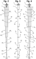
- the distal ends of at least some of the electrodes 3 1 -3 6 are located, instead, at different heights in the direction of length X: with reference, for example, to the case illustrated in Figures 1 to 4 , the two electrodes designated by 3 1 and 3 2 have the respective distal ends E 1 and E 2 substantially at the same height, whereas the other electrodes 3 3 -3 6 have their distal ends E 3 -E 6 at different heights along the axis X.
- This does not constitute an essential characteristic of the invention, but is, however, advantageous for the reasons explained hereinafter.
- the structure 1 is divided, in the direction X, into a succession of different detection areas or sections, which in the example of Figures 1-4 are designated by S1-S5.
- the various sections S1-S4 have substantially the same height (or length), but this does not constitute an essential characteristic.
- the number of the detection sections S1-S5 is smaller than the number of the electrodes 3 1 -3 6 .
- each detection section S1-S5 comprises two effective portions of two respective electrodes 3 1 -3 6 .
- each detection section S1-S5 there extend two effective portions, represented in particular by the pair of portions EP 1 , EP 2 in the section S1, by the pair of portions EP 1 , EP 3 at the section S2, by the pair of portions EP 2 , EP 4 at the section S3, by the pair of portions EP 3 , EP 5 at the section S4, and by the pair of portions EP 4 , EP 6 at the section S5.
- one and the same electrode 3 1 -3 6 may define more than one effective portion, at different heights, each belonging to a different detection section: in the case exemplified, for example, the electrode 3 1 defines respective effective portions EP 1 at the sections S1 and S2, the electrode 3 2 defines respective effective portions EP 2 at the sections S1 and S3, the electrode 3 3 defines respective effective portions EP 3 at the sections S2 and S4, the electrode 3 4 defines respective effective portions EP 4 at the sections S3 and S5, whereas the electrodes 3 5 and 3 6 each define just one effective portion EP 5 and EP 6 at the sections S4 and S5, respectively.
- the distal end E 1 -E 6 of an electrode will be located, according to the cases, at the end of its single effective portion (electrodes 3 5 and 3 6 ) or of its last effective portion (electrodes 3 1 -3 4 ) opposite to the connection structure 2.
- the detection sections there also extends at least one non-effective axial portion of at least one further electrode, namely, of an electrode other than (i.e., different from) the two measuring electrodes to which the two effective portions of the corresponding detection section belong.
- at least one non-effective axial portion of at least one further electrode namely, of an electrode other than (i.e., different from) the two measuring electrodes to which the two effective portions of the corresponding detection section belong.
- the electrodes are shaped in such a way that, at one or more detection sections, the two effective axial portions of two corresponding measuring electrodes are closer to one another than they are to the non-effective axial portion or portions of one or more further electrodes that extend in the detection section considered.
- this particular configuration also enables definition of a detection structure in which the number of electrode axial portions in one detection section differs from the number of electrode axial portions in an adjacent detection section, with consequent advantages described hereinafter.
- the pairs of effective portions EP 1 and EP 2 , EP 1 and EP 3 , EP 2 and EP 4 , EP 3 and EP 5 , EP 4 and EP 6 of the sections S1-S5, respectively, extend to a prevalent extent, in the direction of length X, substantially parallel or equidistant, by a first predetermined distance, from one another.
- each non-effective portion of the further electrode or electrodes present in the section considered extends to a prevalent extent in the length direction X at a second predetermined distance from the corresponding effective portions, with the second predetermined distances that are greater than the first predetermined distance.
- the aforesaid first distance and second distance are preferably understood as distances between the axes of the electrodes considered.
- Figure 5 illustrates partially the sections S1-S3 of the sensor LS of Figures 1-4 .
- denoted by d1 is the aforesaid first distance, for example between the effective portions EP 1 and EP 2 of the electrodes 3 1 and 3 2 in the section S1, or between the effective portions EP 1 and EP 3 of the electrodes 3 1 and 3 3 in the section S2, or between the effective portions EP 2 and EP 4 of the electrodes 3 2 and 3 4 in the section S3.
- d2 are the second distances, between the effective portion EP 1 of the electrode 3 1 and the corresponding non-effective portion (designated by NEP 2 ) of the electrode 3 2 in the section S2, or else between the effective portion EP 2 of the electrode 3 2 and the corresponding non-effective portions (designated by NEP 1 and NEP 3 ) of the electrodes 3 1 and 3 3 at the section S3 (it goes without saying that also the second distance d2 between the effective portion EP 3 of the electrode 3 3 and the corresponding non-effective portion NEP 2 of the electrode 3 2 at the section S2, or else between the effective portion EP 4 of the electrode 3 4 and the corresponding non-effective portions NEP 1 and NEP 3 of the electrodes 3 1 and 3 3 at the section S3, are greater than the distance d1).
- the distance d1 is not necessarily always the same at each detection section S1-S5, and the same may be said as regards the distances d2.
- d2 is much greater than d1, for example from five to forty times greater, preferably from eight to twenty times.
- the aforesaid different distances d1, d2 between the effective portions and the non-effective portions of the various electrodes are obtained by envisaging at least one intermediate step in the electrodes themselves.
- the intermediate steps are designated by D 2 -D 5 in Figures 1 and 4 .
- the electrode 3 1 is substantially straight, i.e., without steps, whereas each of the electrodes 3 2 -3 6 defines along its development at least one intermediate step D 2 -D 5 , respectively.
- the at least one intermediate step is configured in such a way that two consecutive portions of the corresponding electrode 3 2 -3 6 that are located upstream and downstream of the step itself extend substantially parallel to one another or according to axes parallel to one another in the direction of length X.
- the intermediate steps D 2 -D 5 include a stretch of the corresponding electrode 3 2 -3 6 that extends substantially perpendicular to the aforesaid consecutive portions (see, for example, the horizontal stretches of electrode at which the lines of the reference numbers "D 2 " and "D 3 " in Figure 5 terminate).
- one of the two aforesaid consecutive portions will be an effective portion of the electrode considered, whereas the other will be a non-effective portion of the same electrode.
- the values of the distances d1 and d2 at the various detection sections S1-S5 basically depend upon the conformation of the intermediate steps of the electrodes concerned (in particular, upon the length of their stretches transverse or perpendicular to the direction X, possibly including curved radiusing stretches, which are visible in the figures provided by way of example).
- the level sensor LS comprises a plurality of positioning elements, which are set at a distance from one another in the direction of length X and are configured for keeping the various electrodes permanently at the respective predetermined distances, such as the distances previously denoted by d1 and d2, and may possibly be used for fixing the electrodes in the operating conditions, for example within a container.
- the positioning elements are designed to define both a distance (d1) between portions of electrodes that are designed to make a detection and a distance (d2) between portions of electrodes that do not contribute to making a detection.
- the positioning elements are designed to define both a distance (d1) between at least two portions of electrodes of an effective portion and a distance (d2) between at least two portions of electrodes of a non-effective portion.
- the aforesaid positioning elements are designated by 4 and may, for example, comprise two parts 4a and 4b (see Figure 6 ) made of electrically insulating material that can be coupled together, for example by means of threaded members 4c or rivets or snap-action or mechanical-interference engagement elements, with respective stretches of the electrodes set in between.
- various other possible embodiments of the positioning elements 4 will be exemplified, which, where so required, can also be configured for the purposes of fixing in position a corresponding detection section 1 of the sensor LS inside a generic container, for example a tank.
- At least one of the two measuring electrodes that define the two effective portions of a corresponding detection section has its respective distal end in a position substantially corresponding or close to a positioning element of the type mentioned previously, or a little beyond it.
- the aforesaid preferential concept may be appreciated, for example, in Figures 1 and 4 , where it may be noted how the distal ends E 3 -E 6 of each of the electrodes 3 3 -3 6 project slightly beyond a corresponding positioning element 4. This is preferable for guaranteeing the precise positioning and/or proper fixing of the electrodes also in their lower terminal area.
- At least one of the positioning elements 4 is set in the proximity of or in a position corresponding to at least one of the steps D 2 -D 5 , with the aforesaid positioning element that is configured for fixing the level sensor in position.
- Such a positioning of at least one such element 4 can enable fixing of the level sensor in a corresponding tank at areas of bending or variation of direction of the level sensor, corresponding to areas of variation of inclination of the tank.
- each successive detection section will include a number of electrode portions smaller by one than the previous section, however ensuring the presence in the aforesaid section of two effective portions.
- the aforesaid characteristic may be clearly appreciated from Figures 1 , 2, and 4 , where it may be noted how the sections S1, S2, S3, S4, and S5 each include six, five, four, three, and two electrode portions, respectively.
- Figures 6-8 illustrate a possible embodiment of a connection structure 2, which preferentially includes a respective casing, for example formed in two parts 2a and 2b, preferably made of electrically insulating material.
- a part of the casing such as the upper part 2a, defines a connector body 5, within which electrical connection terminals 6 partially extend, for interfacing the level sensor LS to an external system.
- the aforesaid casing is shaped for housing inside it a processing and/or control circuit, to which the electrodes of the detection structure 1 are electrically connected, preferably at their proximal ends.
- the two casing parts 2a and 2b are shaped to define a chamber 7 between them for housing a circuit support 8, on which there may be mounted the circuit components 8a for control of the level sensor, preferably including an electronic control unit, such as a microcontroller with associated non-volatile memory means, in which the program for control of the sensor resides.
- the electronic unit or processing and/or control circuit 2 preferably comprises at least one from among an oscillator circuit or a circuit designed to generate a frequency signal, a circuit designed to detect an impedance and/or a capacitance and/or an electrical resistance, an amplifier circuit, a controllable switch or a multiplexer or a circuit for switching the inputs and/or electrodes, a signal-sampling or sample-and-hold circuit, an analog-to-digital converter, a data-processing circuit, a memory circuit, a data-transmission circuit, preferably for transmission and/or reception in a serial format, very preferably by way of a SENT (Single-Edge Nibble Transmission) interface and/or protocol.
- SENT Single-Edge Nibble Transmission
- this preferably comprises at least one processing and/or control logic unit, a memory circuit and inputs and outputs, amongst which inputs of an analog/digital type.
- the electronic control unit could comprise an integrated circuit of an ASIC or FPGA type and an integrated circuit dedicated to performing the functions of analog-to-digital converter.
- the circuit support 8 is preferably provided with a connection arrangement 8b for the electrodes 3 1 -3 6 , which is connected to the circuit provided by the aforesaid componentry 8a, and moreover connected to the aforesaid circuit are the terminals 6, for example via spring contacts 6a.
- One of the two parts of the casing, here the part 2b, is preferably provided with a passage 9 for the proximal end portions of the electrodes, and to this passage 9 there can be associated suitable sealing means, such as a resin-bonding.
- suitable sealing means such as a resin-bonding.
- sealing means 10 ( Figure 8 ), such as an annular gasket.
- the two casing parts 2a, 2b are fixed together, with the sealing means 10 set in between, for example via threaded members or else with snap-action engagement means or technically equivalent means; in the example illustrated, provided for the purpose are threaded members and an upper fixing ring, designated by 11 and 12, respectively, in Figure 8 .
- the parts of the casing here the part 2b, is provided with elements 13 for positioning and/or fixing the connection structure 2 to a different structure, for example to the outside of a tank.
- control circuit of the level sensor is configured for selectively applying an electrical potential difference, preferably frequency-modulated, between the two measuring electrodes that define the two detection axial portions of a corresponding detection section, and for detecting the value of a given electrical quantity between the aforesaid two detection axial portions, this electrical quantity being representative of the level of the liquid.
- the various electrodes are set electrically insulated from each other, i.e., in the absence of a permanent electrical connection between two or more electrodes, and therefore in the absence of electrical connections in series or in parallel.
- the control circuit is nevertheless preferably configured for connecting to ground the electrodes other than the two measuring electrodes to which the aforesaid difference of potential is applied from time to time.
- the electrical quantity of interest is therefore detected substantially only between the two detection axial portions of the section which is considered from time to time, these detection portions extending to a prevalent extent only in the direction of level detection, and hence without the use of interdigitated conductive elements that extend transversally to the two electrodes, as typically happens in various capacitive sensors according to the prior art.
- the electrical quantity in question may be an impedance or a resistance or a capacitance, and the control circuit will be configured accordingly.
- the electrical quantity measured between the electrodes may be the capacitance, when the liquid is relatively insulating or has a low conductivity (such as diesel or new/non-spent oil), or else the impedance in the case of more conductive liquids (such as urea/AD-Blue, non-deionised water, windscreen-washer liquids, used/spent oil, etc.).
- the capacitance could be measured also in the case of a sensor LS the electrodes of which are electrically insulated with respect to the liquid, for example enclosed in a coating of electrically insulating material substantially impermeable to the liquid, and the liquid is electrically conductive (for example, a water-urea solution). It will appear clear to the person skilled in the art that, at least in the cases where the electrodes are in contact with the liquid, the result of the measurement of capacitance will also depend upon the dielectric constant of the liquid itself, it being possible also to detect a value of impedance or a value of resistance or conductivity of the liquid.
- Figure 9 is a schematic illustration of a sensor LS of the type described previously, mounted inside a generic container T, for example the tank of a vehicle.
- the sensor LS is set in such a way that its section S1 is the one furthest down in the direction of length X.
- the sensor LS could be set upside down with respect to the case illustrated (i.e., with the section S5 furthest down), possibly adapted for this purpose, and in this case the control logic of the sensor itself could be substantially reversed with respect to the one exemplified hereinafter.
- the electrodes 3 1 -3 6 constitute capacitive electrodes: consequently, when the two effective portions of a certain detection section are immersed at least partially in a liquid, the value of capacitance that can be detected between the two corresponding electrodes will be different from the one that can be detected in the absence of liquid (i.e., in the case where the electrodes are not immersed), this value of capacitance depending upon the dielectric constant of the liquid in question.
- the control circuit of the sensor will initially control application of the difference of potential or of the frequency-variable signal between just the electrodes 3 1 and 3 2 , the effective portions EP 1 and EP 2 of which provide the detection section S1.
- the remaining electrodes 3 3 -3 6 may be connected to ground (or to a different electrical potential or not connected to a potential).
- the step of measurement will start from the detection section that is located furthest down inside a container the level of liquid of which is to be measured; however, nothing in principle rules out starting detection with a different sequence, for example starting from the section furthest up (such as the section S5, in the example discussed so far).
- the control circuit measures a value of capacitance between the two electrodes 3 1 and 3 2 , which will be variable as a function the degree of immersion of the two effective portions EP 1 and EP 2 in the liquid L; the circuit then compares the value detected with corresponding reference information contained in suitable non-volatile memory means of the circuit itself, the aforesaid information representing, for each value or range of values of capacitance detected for the given section S1, the corresponding level of liquid L.
- the control circuit is able to know to what extent the effective portions EP 1 and EP 2 of the section S1 are immersed in the liquid L or, conversely, to what extent the aforesaid portions EP 1 and EP 2 are not immersed or are in air (or some other gas), and thereby know the corresponding level of the liquid.
- the control circuit preferably implemented in the connection structure 2, will then transmit or generate signals towards the outside world, for example via the electrical connector 5-6 described previously, these signals representing the level information.
- the corresponding control circuit may be configured for detecting a value of impedance between the electrodes, instead of capacitance, and make the necessary comparisons with corresponding reference information.
- the various sections S1-S5 have a decreasing number of electrode portions, starting from the section closest to the structure 2. This characteristic is advantageous for improving the quality of level detection.
- the capacitance in air C air will be determined by just the non-immersed stretches of the electrode portions of the section S1 present in the liquid.
- the detection section S1 consists of just two adjacent electrode portions (i.e., the effective portions EP 1 and EP 2 of the electrodes 3 1 and 3 2 - see Figure 5 ) the other electrodes of the structure 1 will substantially not give rise to any noise or parasitic capacitance at the aforesaid section S1, or in any case will give rise to very low electrical noise or parasitic capacitances, thereby rendering the level detection more precise.
- the section S1 (or, more in general, each detection section S1-S5), would include - in addition to the respective two effective electrode portions - also further four non-effective portions of the other electrodes.
- Figure 10 illustrates, instead, the case where the amount of liquid L in the container T is such that the level can be detected by the section S2.
- the level-detection step will envisage the steps already explained above in relation to the section S1, i.e., application of the potential difference between the electrodes 3 1 and 3 2 , subsequent detection of the capacitance between the same electrodes, and comparison of the value detected with the reference information.
- the control circuit in addition to recognising that the section S1 is completely immersed in the liquid, will then repeat of the same steps in relation to the overlying section S2, and hence:
- both the effective portions EP 1 and EP 3 of the electrodes 3 1 and 3 3 and the non-effective portion NEP 2 of the electrode 3 2 are partially immersed in the liquid L (see Figure 5 ).
- the non-effective portion NEP 2 is located at distances d2 from the effective portions EP 1 and EP 3 greater than the distance d1 between the effective portions EP 1 and EP 3 : in this way, the effect of electrical disturbance or parasitic capacitance generated by the electrode 3 2 at the section S2 is negligible, or in any case very limited, to the advantage of precision of level detection.
- FIG 11 illustrates the case where the amount of liquid L in the container T is such that the level can be detected by the section S3.
- the detection logic remains the one described above, with the control circuit that, in addition to recognising that the sections S1 and S2 are completely immersed in the liquid, will repeat the steps mentioned above in relation to the overlying section S3.
- both the effective portions EP 2 and EP 4 of the electrodes 3 2 and 3 4 and the non-effective portions NEP 1 and NEP 3 of the electrodes 3 1 and 3 3 are partially immersed in the liquid L (see Figure 5 ).
- the aforesaid non-effective portions NEP 1 and NEP 3 are located at distances d2 greater than the distance d1 between the effective portions EP 2 and EP 4 , in this way minimising the effect of electrical disturbance or parasitic capacitance generated by the electrodes 3 1 and 3 2 at the section S3, to the advantage of precision of level detection.
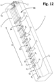
- FIG 12 Illustrated in Figure 12 is a level sensor LS according to further possible embodiments of the invention, mounted within a generic container T of a liquid, for example a tank.
- a liquid for example a tank.
- the sensor LS itself is illustrated in isolation, in front elevation.
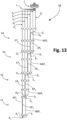
- Figures 12 and 13 likewise illustrate how, in various embodiments, the plurality of electrodes that make up a detection structure 1 may comprise at least one calibration or reference electrode.
- the senor forming the subject of the invention is configured for detecting the level of liquids that might be non-homogeneous and stratified both in terms of composition and in terms of temperature.
- a calibration element at a number of detection sections of one and the same detection structure, in particular at least one calibration element at each pair of effective portions of electrode.
- the various calibration elements may be defined by a single calibration or reference electrode.
- the aforesaid single calibration electrode is shaped for defining a plurality of calibration portions, each of which is locally set alongside, preferably substantially parallel to, one of the effective portions of a corresponding detection section.
- the calibration portions are preferentially positioned in the lowest part of the corresponding detection section so that they can also be used when the liquid laps only a small portion of the effective portions of the corresponding measuring electrodes.
- measuring electrodes designated by 3 1 -3 5
- a single calibration electrode designated by 3 r .
- the measuring electrodes i.e., the respective active portions EP 1 -EP 5
- the respective active portions EP 1 -EP 5 in this case define four detection sections S1-S4..
- the number of the detection sections S1-S4 is smaller than the number of the electrodes 3 1 -3 5 , 3 r .
- the calibration electrode 3 r is shaped, in particular via a plurality of respective intermediate steps D r , so as to define a plurality of calibration portions, each of which - as has been mentioned - extends substantially parallel to the two effective portions of the two measuring electrodes of a corresponding detection section S1-S4.
- the steps D r are preferably configured in such a way that the calibration portion of the electrode 3 r will be parallel to the effective portions of the two measuring electrodes only for a limited stretch.
- each measuring electrode 3 1 -3 5 defines just one respective effective portion EP 1 -EP 5 .
- the steps D r are in a staggered position with respect to the steps D 1 -D 5 .
- EP r are two of the aforementioned calibration portions of the electrode 3 r , which extend in the direction of length substantially parallel to the effective portions EP 1 and EP 3 of the section S1, and to the effective portions EP 2 and EP 3 of the section S2, respectively.
- the calibration portions EP r extend at respective third predetermined distances d3 between their own axes and the axes of the two effective portions of the corresponding detection sections, the aforesaid third distances d3 being shorter than the second predetermined distances d2 referred to previously.
- NEP r portions of the calibration electrode 3 r that extend between an aforesaid calibration portion EP r and a corresponding step D r .
- these portions NEP r extend at a distance d2, from the two effective portions of the corresponding detection sections that is greater than the corresponding distances d1, and preferably also greater than the distances d3.
- d2 is the distance between a portion NEP r and just one (EP 2 and EP 3 ) of the two effective portions of the sections S1 and S2: it will be appreciated, however, that also the distance d2, between each portion NEP r and the other (EP 1 and EP 2 ) of the two effective portions of the sections S1 and S2 is greater than the corresponding distances d1.
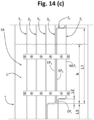
- the calibration portion EP r of the calibration electrode 3 r has a length that is smaller than the length of the two corresponding effective portions of the two measuring electrodes. Also this characteristic may be clearly appreciated in part (a) of Figure 14 , where denoted by L1 is the length - in the direction of length - of the effective portions of the measuring electrodes, whereas denoted by L2 is the length - in the same direction - of the calibration portions of the calibration electrode.
- the length of the calibration portions defined by the calibration electrode is in general smaller than the length of the corresponding effective portions of the measuring electrodes: in general, for effective portions that have a length comprised between 10 and 150 cm, preferably between 5 and 40 cm, the corresponding calibration portions of the calibration electrode will have a length comprised between 0.2 and 10 cm, preferably between 0.5 and 4 cm.
- the calibration process is preferably carried out at the end of the production line, i.e., after the sensor LS has been manufactured, in order to obtain one or more coefficients of correction or compensation of the electrical quantity that represents the level of the liquid (capacitance, or impedance, or resistance).
- the senor may be put in a climatic chamber first at the temperature T1 and then at the temperature T2. Possibly, similar detection sequences may be carried out also with the sensor LS immersed in a liquid with known physical characteristics.
- Detection of the capacitances C air Ref S(n) and C air Eff S(n) (and possibly of the capacitances C liquid Ref S(n) and C liquid Eff S(n) , when envisaged) enables the control circuit, pre-arranged for the purpose, to determine the coefficients of compensation or correction a (n) and b (n) to be employed during actual use of the device.
- Correction or compensation during effective use of the sensor LS is carried out on the basis of the aforesaid coefficients a (n) and b (n) , for example in the way described in what follows (once again assuming that the quantity detected is the capacitance).
- the control circuit of the sensor LS is pre-arranged for measuring a capacitance C m S1 between the effective portions EP 1 and EP 2 of the aforesaid measuring electrodes, and a capacitance C Ref S1 between the corresponding effective portion EP r of the calibration electrode 3 r , having a height L2, and the corresponding stretch of the effective portion EP 2 of the measuring electrode 3 2 at the section S1.
- C m S 1 C air Ref S 1 ⁇ L 1 ⁇ h / L 1 ⁇ a 1 + C Ref S 1 ⁇ h / L 2 ⁇ b 1
- the parameters a1 and b1 are the corrective coefficients for the section S 1 mentioned previously, determined during calibration, as likewise the value of C air Ref S1 .
- C m S(n) can be obtained by assuming two contributions to the capacitance: one due to the liquid (C Ref S1 ⁇ h/L2 ) and one due to the air (C Ref S1 ⁇ h/L2 ⁇ b1).
- the level sensor measures the capacitance between the effective portions of the two measuring electrodes furthest away from the bottom of the container itself that are immersed in the liquid and with respect to the corresponding calibration portion of the calibration electrode (it should be noted that the control circuit is perfectly able to identify the aforesaid pair of effective portions, given that in any case the capacitance detected between them is clearly different from the capacitance that would be detected in the case where the aforesaid effective portions were completely in air).
- part (c) of Figure 14 which exemplifies the case of a level h of liquid L that reaches the section S4 of the detection structure of the sensor, the effective portions EP 4 and EP 5 of the measuring electrodes 3 4 and 3 5 being partially immersed in the aforesaid liquid.
- the parameters a 4 and b 4 are the corrective coefficients for the section S4 mentioned previously, determined during calibration, as likewise the value of C air Ref S4 .
- C Ref S4 measured between the calibration portion EP r of the electrode 3 r and the corresponding stretch of the effective portion EP 5 of the measuring electrode 3 5 , makes it possible to have a reference value for a different area of the container T (as compared to the case of part (b) of Figure 14 ), thus making it possible to take into account the presence of gradients and of lack of homogeneity both of temperature and of composition within the liquid L.
- L3 + h L3 corresponds to the height - known to the control electronics - of the sections S1, S2, and S3, which are evidently immersed in the liquid L, and where h is equal to C m S 4 ⁇ C air Ref S 4 ⁇ a 3 ⁇ b 3 / L 2 ⁇ C Ref S 4 ⁇ a 3 / L 1 ⁇ C air Ref S 4 ⁇ 1
- the control circuit can measure the value C Ref S(n) and compare this measured value with the value stored for calibration in air C air Ref S(n) , obtained during initial calibration as explained previously: the aforesaid detection and comparison step is carried out for each detection section starting from the bottom, i.e., from the section S 1.
- the control circuit can identify the detection section in which the detected value of C Ref S(n) is equal or close to C air Ref S(n) , namely the detection section in which the calibration portion of the electrode 3 r is in air, i.e., is not immersed in the liquid L: at this point, the electronics can identify the value of h, as explained above, for the underlying detection section, and calculate the level of filling as h + L3. In the case where the control electronics does not identify any section where C Ref S(n) is equal or close to C air Ref S(n) , this means that also the last section, i.e., the one furthest up, is immersed in the liquid.
- the level sensor according to the invention comprises a number of level-detection structures, preferably connected to one and the same electrical-connection structure 2.
- Figure 15 illustrates the case of a sensor LS that comprises one first said level-detection structure 1' and one second level-detection structure 1", which extend in generally side-by-side positions in the direction of length X and which are both connected to the structure 2.
- the two structures 1' and 1" are each provided with a calibration electrode 3 r of the type mentioned previously, but this does not constitute a strictly essential characteristic.
- the two or more detection structures may comprise a different number of detection sections.
- the structure 1' includes four detection sections S1-S4, whereas the other structure 1" includes just two sections S1 and S2.
- Configurations of this sort are, for example, useful in the cases where the container or tank containing the liquid the level of which is to be detected includes a number of distinct compartments or else a number of distinct storage areas, for example the so-called saddle tanks, in particular fuel saddle tanks of vehicles.
- Figure 16 exemplifies for this purpose the case of a container or tank with a number of compartments or storage areas distinct from one another, such as a tank for vehicles, for example of the so-called saddle-tank type, the bottom Tb of which is shaped so as to define two distinct lower storage areas denoted by T 1 and T 2 , which are generally parallel to one another, which are overlaid by a common storage area T 3 (of course each of the areas T 1 and T 2 has a respective outlet for the liquid, not represented).
- Each of the two structures 1' and 1" extends, in the direction of length, in part in a respective lower storage area T 1 and T 2 and in part through the common storage area T 3 . It will hence be appreciated that, via the lowest detection section or sections of each structure 1' and 1" (for example, the sections S1 and S2 of each structure of Figure 15 ) it will be possible to detect independently the presence and the level of the liquid in each of the two lower storage areas T 1 and T 2 , whereas the remaining detection sections of the structure 1' (for example, the sections S3 and S4 of the structure 1' of Figure 15 ) may used for detecting the presence and the level of the liquid present in the common storage area T 3 .
- the lowest detection section or sections of each structure 1' and 1" for example, the sections S1 and S2 of each structure of Figure 15
- the remaining detection sections of the structure 1' for example, the sections S3 and S4 of the structure 1' of Figure 15
- a level sensor comprising a number of level-detection structures connected to one and the same electrical-connection structure 2 (as in the example of Figures 15 and 16 ) even only one of the detection structures could comprise sections (such as the sections S3 and S4), dedicated to detection of the presence and of the level of liquid present in a common storage area (such as the area T 3 ).
- supports P are represented, integrated or fixed to at least one side wall Ts of the container or tank T or, more in general, a wall that substantially extends alongside the level sensor 1 or the corresponding electrodes, where the aforesaid supports P are coupled to positioning elements of the level sensor.
- the detection structure or structures of the level sensor has/have a plurality of consecutive areas that extend according to respective planes generally angled with respect to one another, with the various electrodes that have respective bends in a position corresponding to each region of transition between consecutive areas.
- FIG. 17 An example of this type is illustrated in Figure 17 , where the level sensor LS is built in a way similar to the one shown in Figure 15 and comprises two detection structures 1' and 1" set alongside one another in the direction of length X.
- Each structure 1' and 1" substantially includes three different areas differently inclined with respect to one another in the direction X, which are denoted by A1, A2, and A3.
- A1, A2, and A3 the electrodes of the two sections 1' and 1" have respective bends; the aforementioned regions of transition are denoted by B1 and B2 in Figure 17 .
- the areas A1 of the two structures 1' and 1" substantially include portions of the various electrodes, which basically have the purpose of providing a connection to the structure 2, i.e., portions that are not effective for the purposes of the level detection; likewise, the area A2 of the structure 1" does not include level-detection sections either, whereas the area A2 of the structure 1' includes just the detection section S4; finally, the area A3 of the structure 1' includes the respective detection sections S3, S2, and S1, whereas the area A3 of the structure 1" includes the respective detection sections S2 and S1. Configurations of this sort may prove useful in the case of containers for liquid, for example vehicle tanks, that have complex geometrical configurations, for example distinguished by the presence of walls with irregular profile that do not allow the use of a rectilinear detection structure.
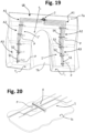
- Figures 18 and 19 exemplify the case of a container 7 with two compartments or of the saddle type, for example a vehicle tank, which has a shaped intermediate area Th, substantially having a vault shape, which defines within the container T two areas T 1 and T 2 for storage of liquid, as already seen in relation to Figure 16 .
- the bottom wall is moreover distinguished, at least at each area T 1 and T 2 , and preferably also at the area T 3 , by wall portions that are angled with respect to one another.
- these wall portions are denoted by Tb1, Tb2, and Tb3, of which at least the wall portions Tb2 and Tb3 correspond to the storage area T 2 : for simplicity, it will be assumed that the bottom wall Tb is shaped in a similar way at the area T 1 , (even though in this area T 1 the bottom wall could be differently angled, or even substantially plane).
- the level sensor LS is in this case secured to the upper wall Tu of the container T, thanks to supports P of different height, which substantially extend towards the bottom wall Tb.
- the arrangement is such that the lower ends of the lower detection sections of the sensor LS, i.e., the sections S1 of the two structures 1' and 1", are each located in the proximity of the bottom wall Tb, whereas the upper end of the detection section S4 of the structure 1' is located in the proximity of the upper wall Tu.
- Exemplified in Figures 20 to 33 are various possible embodiments of positioning and/or fixing elements that can be used for securing in relative positions the electrodes at each detection section of the level sensor LS, i.e., or can be used for fixing a sensor LS or the corresponding electrodes in a position corresponding to at least one wall Tu, Tb, Ts of the container or tank T.
- Figures 20-21 illustrate the case of a positioning element 4, the body of which is designed to extend in a direction transverse to the electrodes of a section of detection structure and that includes two portions that can be closed by snap action, with respective stretches of the electrodes set in between.
- the aforesaid body may be conveniently made of a suitable plastic material, for example via moulding.
- two elongated portions 20a and 20b are thus provided, joined together by a hinge portion 20c, where, at the end of the portion 20b opposite to the hinge portion 20c, a hooking element 20d may be provided, for example in the form of an elastic tooth, to secure firmly the two parts 20a and 20b to one another.
- the lower portion of the element 4, here the portion 20a, is provided with a part 20e for fixing, for example via snap action, or in a threaded way, or with interference, to a corresponding support P defined in a wall of the container containing the liquid the level of which is to be detected, for example a side wall Ts.
- transverse positioning seats 20f are defined for corresponding electrodes of a detection structure 1.
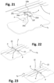
- Figures 22-24 represent a positioning element 4, the body of which is overmoulded in a direction transverse to corresponding stretches of the electrodes of a structure 1 and which defines, at its two ends, through seats (not indicated) for corresponding members for fixing to two supports P.
- the aforesaid fixing members, designated by 22 engage in a snap-action way or with interference, whereas in the case of Figure 24 threaded members or rivets 22' are provided.
- Figures 25-26 regard a version of positioning element similar to that of Figures 20-21 but in which the two body portions 20a and 20b are configured as distinct parts.
- one of the two portions - here the portion 20b - has at its two opposite ends respective hooks 20d, for example in the form of elastic teeth, for blocking the portion 20b on the portion 20a, with respective stretches of the electrodes set in between.
- the portion 20a is provided with a part 20e for fixing, for example via snap action, or by threaded connection, or with interference, to a corresponding support P, and defined in at least one of the facing surfaces of the portions 20a and 20b are transverse positioning seats 20f for the electrodes.
- Figure 27 illustrates a solution of a positioning element, which is structurally similar to that of Figures 25-26 , but in which the hooks 20d are provided with levering tabs 20g aimed at facilitating, in the case of need, divarication of the hooks themselves, and hence the separation of the portions 20a and 20b.
- Figures 28 and 29 exemplify a positioning element 4 in which elastic-engagement seats are provided for corresponding electrodes of a detection structure 1.
- the body of the element 4 consists of a transverse portion 20a, provided at the bottom with a part 20e for fixing to a support P, and provided at the top with elastic engagement elements 20h for engaging corresponding electrodes.
- the engagement elements 20h may, for example, comprise two elastically flexible tabs, which rise substantially parallel from the portion 20a and have respective mutually facing inner surfaces.
- a relief for example in the form of a tooth, which elastically faces or is pressed against the inner surface of the second opposite tab, for example at an area corresponding to a homologous tooth of the aforesaid second tab.
- the relief or reliefs can define an upper inclined plane so as to favour insertion of an electrode between the two tabs.
- the electrode is pressed between the two tabs, in the direction of the portion 20a of the element 4, in order to bring about elastic divarication of the tabs themselves and thereby enable the electrode to pass beyond the relief or reliefs mentioned previously.
- the tabs once again assume elastically their generally parallel configuration so that the relief or reliefs withhold the electrode in position.
- a transverse seat may be defined for at least partial housing of a corresponding stretch of the electrode.
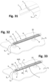
- Figures 30 and 31 regard a positioning element that is defined integrally, in a single piece, with a wall Ts of the container the level of liquid in which is to be measured, i.e., a positioning element 4 that integrates also the function of supporting the elements designated previously by P.
- the wall Ts in question preferably made of a plastic material, is moulded in such a way that its respective portions, which provide the elements 4, surround the electrodes: basically, then, the wall Ts is locally overmoulded on respective stretches of the electrodes.
- Figures 32 to 33 exemplify the case where the positioning element 4 includes a longitudinally extending body that is overmoulded on at least one corresponding longitudinally extending portion of a detection structure, i.e., on two or more electrodes thereof.
- a through opening H in the form of slot is defined in the body overmoulded at an area comprised between the effective portion EP 2 of the electrode 3 2 and a non-effective portion NEP r of the calibration electrode 3 r ; another through opening (not indicated), in the form of a hole, is instead provided in the overmoulded body in position corresponding to the fixing member designated by 22'.
- the positioning members of the detection structure of a level sensor according to the invention do not necessarily all have to be the same as one another, it being possible to envisage, for example, the combined use of different elements 4 according to Figures 20 to 32 .
- the electrodes of the level sensor according to the invention do not necessarily have to be in contact with the liquid, it being possible for them to be isolated therefrom.
- at least the detection structure 1 of the sensor, or each detection structure 1', 1" thereof may be provided with an electrically insulating coating or casing.
- Such a casing may be at least in part formed by an overmoulding of electrically insulating material, or else in at least two parts fixed together in a fluid-tight way, for example welded or glued, with the electrodes set in between.
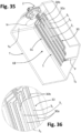
- Figure 34 illustrates, for example, a version of sensor LS with electrodes isolated from the liquid, i.e., provided with a casing or coating designated as a whole by 30.
- the casing 30 may include two parts 30a and 30b associated to one another with the electrodes set in between, for example welded together.
- a part 30a is substantially plane, whereas the part 30b has a profile at least in part complementary to that of the electrodes, it being, for example, possible to obtain this shaping during assembly, in particular when the part 30b is sufficiently thin (for example, in the form of a film) and is heat-sealed on the part 30a.
- the part 30a can also be relatively thicker than the part 30b, in order to obtain a sort of supporting structure for the electrodes, even though this is not strictly necessary.
- the casing 30 may also be exploited in order to fix the sensing part of the sensor inside a container T, as exemplified in Figures 34 to 35 , in particular exploiting supports P integrated in the container itself, as mentioned previously.
- the two parts of the casing 30 could, however, be the same as, or symmetrical to, one another, i.e., each having a profile at least in part complementary to a respective part of the electrodes, for example in the form of films.
- the casing can perform completely or partially the function of ensuring proper relative positioning of the electrodes, for example at the distances d1, d2 and possibly d3 mentioned previously.
- the coating 30 could also be of an overmoulded type, or else in the form of an insulating layer or coating applied on the electrodes, such as a layer made of Teflon or other electrically insulating material.
- the coating is preferably designed as a whole for enclosing all the electrodes of the sensor, as in the case exemplified, but not ruled out is the case of a coating formed by a number of parts that each enclose a single electrode: consider, for example, an electrode enclosed in a respective sheath, such as an electrically insulated wire, in which case it will, however, be preferable to envisage a plurality of positioning elements, for example of the types designated previously by 4. Insulating shells could, moreover, be obtained starting from plane sheets, shaped by thermoforming and welded together using any known technique, such as vibration welding, hot-blade welding, laser welding, etc.
- the conductive elements of the sensor could be obtained from metal foils (steel, aluminium, copper, or other suitable conductor) and shaped like electrodes using techniques of selective chemical etching (for example, the technique also known by the term "etched foil").
- the thickness of the foils may be comprised between 1 and 500 ⁇ m, preferably comprised between 30 and 150 ⁇ m.
- the protective layers may, for example, be constituted by polymeric films of a thickness comprised between 10 and 600 ⁇ m, preferably between 40 and 150 ⁇ m.
- the covering foils or films may be chosen on the basis of the type of chemical agents in which the sensor is to operate, for example high-density polyethylene (HDPE), polypropylene, polymeric multilayer films with high barrier effect, etc.
- HDPE high-density polyethylene
- polypropylene polypropylene
- polymeric multilayer films with high barrier effect etc.
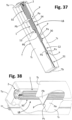
- Figures 37 and 38 exemplify a further possible variant embodiment, in which the supports P integrated in the container T that are to receive the level sensor define respective seats in which there can be locally inserted a detection section of the sensor.
- the supports P may in this case comprise, for example, opposed walls that define between them a slit or gap, in which the detection section of the sensor can be inserted in a transverse direction.
- Applications of this type are particularly advantageous in the case where the detection structure 1 of the sensor, or each detection structure 1', 1" thereof, includes an insulating casing having as a whole a prevalently plane and/or thin structure, such as a casing of the type designated previously by 30.
- the casing 30 is sufficiently rigid to ensure maintenance of the correct relative position between the electrodes, without any need for positioning elements of the type designated previously by 4.
- a series of supports P set at a distance from one another in the direction of length, to which the detection structure 1, i.e., its casing 30, is locally constrained.
- each support P defines a seat, one of which is designated by Ps in Figure 38 , in which the detection structure 1, i.e., its casing 30, can be inserted in a transverse direction (i.e., flat).
- the supports P each comprise two small walls Pa and Pb that project towards one another. The upper ends of the two opposed small walls Pa and Pb define between them a slit, which forms the seat Ps, between which there can be inserted - possibly with slight interference - a corresponding part of the casing 30 of the sensor LS.
- the small walls Pa and Pb may, for example, be defined each by a respective side wall Ts of the container T, or else may be defined, and project from, one and the same side wall Ts.
- one or both of the small walls Pa and Pb of each support P will be sized or shaped so as not to obstruct inflow and outflow of the liquid the level of which in the container T is to be measured.
- the invention has been described with particular reference to detection of the level of a liquid medium, but, as mentioned, the sensor described can be used in combination with different substances and materials, even ones that may potentially undergo solidification, for example on account of freezing.
Landscapes
- Physics & Mathematics (AREA)
- Engineering & Computer Science (AREA)
- Power Engineering (AREA)
- Fluid Mechanics (AREA)
- General Physics & Mathematics (AREA)
- Thermal Sciences (AREA)
- Electromagnetism (AREA)
- Measurement Of Levels Of Liquids Or Fluent Solid Materials (AREA)
- Geophysics And Detection Of Objects (AREA)
- Air Bags (AREA)
- Near-Field Transmission Systems (AREA)
Claims (15)
- Füllstandsensor (Level Sensor, LS) zum Erfassen des Füllstandes eines Mediums (L), insbesondere eines flüssigen Mediums, umfassend eine elektrische Verbindungsstruktur (2) und mindestens eine Füllstandserfassungsstruktur (1; 1', 1"),wobei die mindestens eine Füllstandserfassungsstruktur (1; 1', 1") eine Vielzahl von länglichen Elektroden (31-36; 31-35, 3r) umfasst, die mindestens drei Füllstandsmesselektroden (31-36; 31-35) und möglicherweise auch eine Kalibrier- oder Referenzelektrode (3r) umfassen, wobei die länglichen Elektroden (31-36; 31-35, 3r) elektrisch mit der elektrischen Verbindungsstruktur (2) verbunden sind,wobei sich die länglichen Elektroden (31-36; 31-35, 3r) zumindest teilweise in einer Längsrichtung (X) der mindestens einen Füllstandserfassungsstruktur (1; 1', 1") erstrecken und jeweils ein proximales Ende und ein distales Ende (E1-E6) in Bezug auf die elektrische Verbindungsstruktur (2) aufweisen,wobei die mindestens eine Füllstandserfassungsstruktur (1; 1', 1") in der Längsrichtung (X) in eine Folge von Füllstandserfassungsabschnitten (S1-S5; S1-S4) unterteilt ist, von denen jeder zwei wirksame Abschnitte (EP1-EP6; EP1-EP5) von zwei jeweiligen Füllstandsmesselektroden (31-36; 31-35) beinhaltet, wobei sich die beiden wirksamen Abschnitte (EP1-EP6; EP1-EP5) in der Längsrichtung (X) im Wesentlichen parallel oder äquidistant in einem ersten vorgegebenen Abstand (d1) zueinander erstrecken,wobei sich in einem oder mehreren ersten Füllstandserfassungsabschnitten (S2-S5; S1-S4) in der Längsrichtung (X) auch ein nicht wirksamer Abschnitt (NEP1, NEP2, NEP3) mindestens einer weiteren länglichen Elektrode erstreckt, bei der es sich um eine andere als die beiden Füllstandsmesselektroden handelt, welche die beiden wirksamen Abschnitte (EP1-EP6; EP1-EP5) des entsprechenden ersten Füllstandserfassungsabschnitts (S2-S5; S1-S4) definieren, wobei die mindestens eine weitere längliche Elektrode eine der Füllstandsmesselektroden (31-36; 31-35) oder auch eine der möglichen Kalibrier- oder Referenzelektroden (3r) ist,wobei die länglichen Elektroden (31-36; 31-35, 3r) so geformt sind, dass an einem oder mehreren der ersten Füllstandserfassungsabschnitte (S2-S5; S1-S4) der nicht wirksame Abschnitt (NEP1, NEP2, NEP3) der mindestens einen weiteren länglichen Elektrode (31-36; 31-35, 3r) sich in der Längsrichtung (X) in jeweiligen zweiten vorgegebenen Abständen (d2; d2, d2r) von den entsprechenden zwei wirksamen Abschnitten (EP1-EP6; EP1-EP5) erstreckt, wobei die zweiten vorgegebenen Abstände (d2) größer als der erste vorgegebene Abstand (d1) sind.
- Sensor nach Anspruch 1, wobei zumindest einige der länglichen Elektroden (32-36; 32-35, 3r) zumindest eine Zwischenstufe (D2-D5; D2-D5, Dr) definiert, die insbesondere zumindest einen quer zur Längsrichtung (X) verlaufenden oder geneigten oder gewölbten Elektrodenabschnitt umfasst.
- Sensor nach Anspruch 1 oder Anspruch 2, wobei die distalen Enden (E1-E6; E1-E5, Er) mindestens einiger der länglichen Elektroden (31-36; 31-35, 3r) in der Längsrichtung (X) unterschiedlich hoch sind.
- Sensor nach einem der Ansprüche 1 bis 3, der eine Steuerschaltung (5, 5a) umfasst, die zu Folgendem konfiguriert ist:- selektives Anlegen einer elektrischen Potentialdifferenz zwischen den beiden Füllstandsmesselektroden (31-36; 31-35), die die beiden wirksamen Abschnitte (EP1-EP6; EP1-EP5) eines entsprechenden ersten Füllstandserfassungsabschnitts (S1-S5; S1-S4) definieren,- selektives Erfassen eines Wertes einer gegebenen elektrischen Größe zwischen den beiden Füllstandsmesselektroden (31-36; 31-35), ausgewählt aus Impedanz, Kapazität, Widerstand; und- Bestimmen des Füllstands des Mediums auf der Grundlage dieses Werts,wobei vorzugsweise:- die Steuerschaltung (5, 5a) dazu konfiguriert ist, die länglichen Elektroden, die nicht die beiden Füllstandsmesselektroden (31-36; 31-35) sind, mit Masse zu verbinden, und/oder- die Steuerschaltung (5, 5a) in einem Gehäuse (2a-2b) untergebracht ist, das zu der elektrischen Verbindungsstruktur (2) gehört, wobei die proximalen Enden der länglichen Elektroden (31-36; 31-35, 3r) elektrisch mit der Steuerschaltung (5, 5a) verbunden sind, wobei das Gehäuse (2a-2b) vorzugsweise einen elektrischen Verbinder (6, 7) für den externen Anschluss des Füllstandsensors (LS) enthält.
- Sensor nach einem der Ansprüche 1-4, umfassend eine Vielzahl von in Längsrichtung (X) voneinander beabstandete Positionierungselementen (4), die dazu konfiguriert sind, die länglichen Elektroden (31-36; 31-35, 3r) in jeweils vorgegebenen Abständen (d1, d2; d1, d2, d3, d2r) zu halten und/oder die länglichen Elektroden (31-36; 31-35, 3r) an mindestens einer Wand eines Behälters oder Tanks (T) zu fixieren.
- Sensor nach Anspruch 2, wobei die mindestens eine Zwischenstufe (D2-D5; D2-D5, Dr) so ausgebildet ist, dass zwei aufeinanderfolgende Abschnitte der entsprechenden länglichen Elektrode (31-36; 31-35, 3r), die sich stromaufwärts und stromabwärts der mindestens einen Zwischenstufe (D2-D5; D2-D5, Dr) befinden, im Wesentlichen parallel zueinander verlaufen, wobei die mindestens eine Zwischenstufe (D2-D5; D2-D5, Dr) vorzugsweise einen Abschnitt der entsprechenden länglichen Elektrode (31-36; 31-35, 3r) beinhaltet, der sich im Wesentlichen senkrecht zu den aufeinanderfolgenden Abschnitten erstreckt.
- Sensor nach einem der Ansprüche 1 bis 6, wobei die Vielzahl der länglichen Elektroden (31-36; 31-35, 3r) eine Kalibrier- oder Referenzelektrode (3r) umfasst, die so geformt ist, dass sie einen oder mehrere Kalibrier- oder Referenzabschnitte (EPr) definiert.
- Sensor nach Anspruch 7, wobei sich der Kalibrier- oder Referenzabschnitt (EPr) oder jeder Kalibrier- oder Referenzabschnitt (EPr) in der Längsrichtung (X) im Wesentlichen parallel zu den beiden wirksamen Abschnitten (EP1-EP6; EP1-EP5) der beiden Füllstandsmesselektroden (31-36; 31-35) eines entsprechenden ersten Füllstandserfassungsabschnitts (S1-S4) in jeweiligen dritten vorgegebenen Abständen (d3) von den beiden wirksamen Abschnitten (EP1-EP6; EP1-EP5) erstrecken, wobei die dritten vorgegebenen Abstände (d3) kürzer sind als die zweiten vorgegebenen Abstände (d2; d2, d2r), wobei der Kalibrier- oder Referenzabschnitt (EPr) oder jeder Kalibrier- oder Referenzabschnitt (EPr) der Kalibrier- oder Referenzelektrode (3r) eine Länge (L2) hat, die kürzer ist als die Länge (L1) der beiden wirksamen Abschnitte (EP1-EP6; EP1-EP5) der beiden Füllstandsmesselektroden (31-36; 31-35) des entsprechenden ersten Füllstandserfassungsabschnitts (S1-S4).
- Sensor nach einem der Ansprüche 1 bis 8, wobei die mindestens eine Füllstandserfassungsstruktur (1; 1', 1") eine Vielzahl von aufeinanderfolgenden Bereichen (A1, A2, A3) aufweist, die sich gemäß entsprechenden Ebenen erstrecken, die im Allgemeinen in einem Winkel zueinander stehen, wobei die länglichen Elektroden (31-36; 31-35, 3r) in jedem Übergangsbereich (B1, B2) zwischen zwei aufeinanderfolgenden Bereichen entsprechende Biegungen aufweisen.
- Sensor nach einem der Ansprüche 1 bis 9, umfassend mindestens eine erste Füllstandserfassungsstruktur (1') und eine zweite Füllstandserfassungsstruktur (1"), die vorzugsweise nebeneinander verlaufen.
- Sensor nach einem der Ansprüche 1-10, wobei die länglichen Elektroden (31-36; 31-35, 3r) zumindest teilweise von einer Beschichtung aus elektrisch isolierendem Material (4; 30) umgeben sind, das für das Medium (L) im Wesentlichen undurchlässig ist.
- Sensor nach einem der Ansprüche 1-11, wobei die Anzahl der ersten Füllstandserfassungsabschnitte (S1-S5; S1-S4) kleiner ist als die Anzahl der länglichen Elektroden (31-36; 31-35, 3r), und die länglichen Elektroden (31-36; 31-35, 3r) an jedem ersten Füllstandserfassungsabschnitt (S1-S5; S1-S4) elektrisch voneinander isoliert sind.
- Behälter oder Tank für ein flüssiges Medium, insbesondere ein Fahrzeugtank, mit einem Füllstandssensor (LS) nach einem der Ansprüche 1 bis 12.
- Behälter oder Tank nach Anspruch 13, der mindestens zwei nebeneinander verlaufende Bereiche (T1, T2) zur Lagerung des Mediums definiert, wobei der Füllstandssensor (LS) zwei der genannten Füllstandserfassungsstrukturen (1', 1") umfasst, die sich jeweils zumindest teilweise in einem der genannten Bereiche (T1, T2) zur Lagerung des Mediums erstrecken, wobei der Behälter oder Tank insbesondere ein Satteltank ist.
- Behälter oder Tank nach Anspruch 13 oder Anspruch 14, der im Inneren eine Vielzahl von Stützelementen (P) zur Fixierung mindestens einer Füllstandserfassungsstruktur (1; 1', 1") aufweist, wobei die Stützelemente in Längsrichtung voneinander beabstandet sind und vorzugsweise zur Kopplung mit jeweiligen Positionierungselementen (4) der mindestens einen Füllstandserfassungsstruktur (1; 1', 1") ausgebildet sind.
Applications Claiming Priority (2)
| Application Number | Priority Date | Filing Date | Title |
|---|---|---|---|
| IT102018000009136A IT201800009136A1 (it) | 2018-10-03 | 2018-10-03 | Sensore per la rilevazione del livello di un mezzo |
| PCT/IB2019/058432 WO2020070690A1 (en) | 2018-10-03 | 2019-10-03 | A level sensor for detecting the level of a medium |
Publications (3)
| Publication Number | Publication Date |
|---|---|
| EP3861304A1 EP3861304A1 (de) | 2021-08-11 |
| EP3861304C0 EP3861304C0 (de) | 2024-08-07 |
| EP3861304B1 true EP3861304B1 (de) | 2024-08-07 |
Family
ID=65244447
Family Applications (1)
| Application Number | Title | Priority Date | Filing Date |
|---|---|---|---|
| EP19794654.4A Active EP3861304B1 (de) | 2018-10-03 | 2019-10-03 | Füllstandssensor zur erkennung des füllstandes eines mediums |
Country Status (7)
| Country | Link |
|---|---|
| US (1) | US11982561B2 (de) |
| EP (1) | EP3861304B1 (de) |
| JP (1) | JP7418422B2 (de) |
| KR (1) | KR102884875B1 (de) |
| CN (1) | CN113196018B (de) |
| IT (1) | IT201800009136A1 (de) |
| WO (1) | WO2020070690A1 (de) |
Families Citing this family (9)
| Publication number | Priority date | Publication date | Assignee | Title |
|---|---|---|---|---|
| LU100942B1 (en) * | 2018-10-02 | 2020-04-02 | Luxembourg Patent Co | Capacitive Gauge with Lamellar Electrodes held by Spacer(s) |
| IT201800009140A1 (it) * | 2018-10-03 | 2020-04-03 | Eltek Spa | Sensore capacitivo per la rilevazione del livello di un mezzo |
| CN114599964B (zh) * | 2019-10-28 | 2026-01-09 | 索尼集团公司 | 传感器装置和水分含量测量装置 |
| US11668595B1 (en) * | 2021-09-10 | 2023-06-06 | Consolidated Nuclear Security, LLC | Fluid level and conductivity sensor for high temperature applications |
| CN114486542B (zh) * | 2021-12-28 | 2024-01-12 | 安徽云蒙仪表有限公司 | 一种玻璃管液位计用玻璃管检测装置 |
| CN114675676B (zh) * | 2022-03-15 | 2024-10-11 | 东莞南玻太阳能玻璃有限公司 | 液面深度调节方法和装置、电子设备、存储介质 |
| CN114812758B (zh) * | 2022-04-12 | 2025-05-13 | 北京小米移动软件有限公司 | 液位传感器的校准方法、装置、电子设备及存储介质 |
| TWI866547B (zh) * | 2023-10-20 | 2024-12-11 | 神基科技股份有限公司 | 液體入侵偵測裝置、液體入侵偵測方法及其電腦系統 |
| CN117629347B (zh) * | 2024-01-25 | 2024-05-03 | 北京博泰至淳生物科技有限公司 | 一种电极液位计及其使用方法 |
Citations (1)
| Publication number | Priority date | Publication date | Assignee | Title |
|---|---|---|---|---|
| US8161814B2 (en) * | 2008-06-09 | 2012-04-24 | Luna Labs, Inc. | Self-calibrating capacitive transducer for determining level of fluent materials |
Family Cites Families (11)
| Publication number | Priority date | Publication date | Assignee | Title |
|---|---|---|---|---|
| DE2908449C2 (de) | 1979-03-05 | 1986-04-03 | Vdo Adolf Schindling Ag, 6000 Frankfurt | Einrichtng zur kapazitiven Füllstandsmessung insbesondere in einem Kraftfahrzeugtank |
| EP1677083A1 (de) * | 2004-12-22 | 2006-07-05 | Roxer Industries S.A. | Liquid level sensor |
| JP2009025038A (ja) | 2007-07-17 | 2009-02-05 | Toyo Tanso Kk | 液面検出回路及び液面検出システム |
| DE112011104716B4 (de) | 2011-01-14 | 2018-07-12 | Toyota Jidosha Kabushiki Kaisha | Flüssigkeitszustandserfassungssensor |
| GB201214658D0 (en) * | 2012-08-16 | 2012-10-03 | Univ Bradford | Conductivity device |
| FR2996673B1 (fr) | 2012-10-05 | 2016-02-05 | Bostik Sa | Capteur capacitif pour la detection de presence d'un objet et/ou d'un individu. |
| JP2014092453A (ja) | 2012-11-02 | 2014-05-19 | Aisan Ind Co Ltd | センサ装置 |
| GB2519783A (en) * | 2013-10-30 | 2015-05-06 | Airbus Operations Ltd | Capacitive liquid level sensor |
| EP3149435B1 (de) * | 2014-05-30 | 2025-04-30 | Eltek S.p.A. | Sensor zur erkennung des füllstandes eines mediums |
| CN107110690A (zh) * | 2014-09-15 | 2017-08-29 | 埃尔特克有限公司 | 用于检测介质的水平的传感器 |
| EP3194909B1 (de) | 2014-09-15 | 2024-11-13 | Eltek S.p.A. | Sensor zur erkennung des füllstandes eines mediums |
-
2018
- 2018-10-03 IT IT102018000009136A patent/IT201800009136A1/it unknown
-
2019
- 2019-10-03 KR KR1020217013456A patent/KR102884875B1/ko active Active
- 2019-10-03 WO PCT/IB2019/058432 patent/WO2020070690A1/en not_active Ceased
- 2019-10-03 US US17/282,222 patent/US11982561B2/en active Active
- 2019-10-03 JP JP2021518466A patent/JP7418422B2/ja active Active
- 2019-10-03 EP EP19794654.4A patent/EP3861304B1/de active Active
- 2019-10-03 CN CN201980079975.9A patent/CN113196018B/zh active Active
Patent Citations (1)
| Publication number | Priority date | Publication date | Assignee | Title |
|---|---|---|---|---|
| US8161814B2 (en) * | 2008-06-09 | 2012-04-24 | Luna Labs, Inc. | Self-calibrating capacitive transducer for determining level of fluent materials |
Also Published As
| Publication number | Publication date |
|---|---|
| US11982561B2 (en) | 2024-05-14 |
| US20210333140A1 (en) | 2021-10-28 |
| KR20210093241A (ko) | 2021-07-27 |
| EP3861304C0 (de) | 2024-08-07 |
| WO2020070690A1 (en) | 2020-04-09 |
| KR102884875B1 (ko) | 2025-11-12 |
| CN113196018A (zh) | 2021-07-30 |
| JP2022504175A (ja) | 2022-01-13 |
| CN113196018B (zh) | 2024-05-28 |
| IT201800009136A1 (it) | 2020-04-03 |
| EP3861304A1 (de) | 2021-08-11 |
| JP7418422B2 (ja) | 2024-01-19 |
Similar Documents
| Publication | Publication Date | Title |
|---|---|---|
| US11982561B2 (en) | Level sensor for detecting the level of a medium | |
| EP3149435B1 (de) | Sensor zur erkennung des füllstandes eines mediums | |
| US8590375B2 (en) | Self-calibrating capacitive liquid level sensor assembly and method | |
| EP3394578B1 (de) | Vorrichtung und verfahren zur detektion des füllstands eines mediums | |
| US4176553A (en) | Liquid level measuring system | |
| KR20070091155A (ko) | 용량성 액체 레벨 센서 및 레벨 평가 방법 | |
| EP2438405A1 (de) | Flugzeug-treibstoffstandmessvorrichtung und verfahren | |
| GB2043261A (en) | Liquid level sensor | |
| CN102980630A (zh) | 一种智能数字电容液位传感器 | |
| WO2010109317A1 (en) | Capacitive measurement of fuel level and dielectric constant | |
| EP3861303B1 (de) | Kapazitiver sensor zur detektion des füllstands eines mediums | |
| JP2007064933A (ja) | 液体レベル検出装置の補正方法および液体レベル検出装置 | |
| US12442676B2 (en) | Differentiating between fuel and water using capacitive measurement thereof | |
| JP5692020B2 (ja) | 液位検出装置 | |
| JP2013221752A (ja) | 液体濃度検出装置 | |
| ITUA20164395A1 (it) | Sensore per la rilevazione del livello di un mezzo | |
| CN202994244U (zh) | 一种智能数字电容液位传感器 | |
| JP4795049B2 (ja) | 液面レベルセンサ | |
| WO2022216601A1 (en) | Differentiating between fuel and water using capacitive measurement thereof | |
| KR19990024322A (ko) | 액체용량 감지장치 | |
| RU2651638C1 (ru) | Способ измерения уровня границы раздела сред инвариантный к величине диэлектрической проницаемости сред | |
| JP5507022B1 (ja) | 静電容量式燃料レベルゲージ | |
| SK1852021U1 (sk) | Kapacitná sonda na meranie zaplnenia zásobníka kvapalným médiom | |
| ITUA20164410A1 (it) | Sensore per la rilevazione del livello di un mezzo | |
| ITUA20164400A1 (it) | Sensore per la rilevazione del livello di un mezzo |
Legal Events
| Date | Code | Title | Description |
|---|---|---|---|
| STAA | Information on the status of an ep patent application or granted ep patent |
Free format text: STATUS: UNKNOWN |
|
| STAA | Information on the status of an ep patent application or granted ep patent |
Free format text: STATUS: THE INTERNATIONAL PUBLICATION HAS BEEN MADE |
|
| PUAI | Public reference made under article 153(3) epc to a published international application that has entered the european phase |
Free format text: ORIGINAL CODE: 0009012 |
|
| STAA | Information on the status of an ep patent application or granted ep patent |
Free format text: STATUS: REQUEST FOR EXAMINATION WAS MADE |
|
| 17P | Request for examination filed |
Effective date: 20210401 |
|
| AK | Designated contracting states |
Kind code of ref document: A1 Designated state(s): AL AT BE BG CH CY CZ DE DK EE ES FI FR GB GR HR HU IE IS IT LI LT LU LV MC MK MT NL NO PL PT RO RS SE SI SK SM TR |
|
| DAV | Request for validation of the european patent (deleted) | ||
| DAX | Request for extension of the european patent (deleted) | ||
| STAA | Information on the status of an ep patent application or granted ep patent |
Free format text: STATUS: EXAMINATION IS IN PROGRESS |
|
| 17Q | First examination report despatched |
Effective date: 20230103 |
|
| REG | Reference to a national code |
Ref country code: DE Ref legal event code: R079 Free format text: PREVIOUS MAIN CLASS: G01F0023260000 Ipc: G01F0023263000 Ref document number: 602019056647 Country of ref document: DE |
|
| RIC1 | Information provided on ipc code assigned before grant |
Ipc: G01F 23/263 20220101AFI20240228BHEP |
|
| GRAP | Despatch of communication of intention to grant a patent |
Free format text: ORIGINAL CODE: EPIDOSNIGR1 |
|
| STAA | Information on the status of an ep patent application or granted ep patent |
Free format text: STATUS: GRANT OF PATENT IS INTENDED |
|
| INTG | Intention to grant announced |
Effective date: 20240418 |
|
| GRAS | Grant fee paid |
Free format text: ORIGINAL CODE: EPIDOSNIGR3 |
|
| GRAA | (expected) grant |
Free format text: ORIGINAL CODE: 0009210 |
|
| STAA | Information on the status of an ep patent application or granted ep patent |
Free format text: STATUS: THE PATENT HAS BEEN GRANTED |
|
| AK | Designated contracting states |
Kind code of ref document: B1 Designated state(s): AL AT BE BG CH CY CZ DE DK EE ES FI FR GB GR HR HU IE IS IT LI LT LU LV MC MK MT NL NO PL PT RO RS SE SI SK SM TR |
|
| REG | Reference to a national code |
Ref country code: GB Ref legal event code: FG4D |
|
| REG | Reference to a national code |
Ref country code: CH Ref legal event code: EP |
|
| REG | Reference to a national code |
Ref country code: IE Ref legal event code: FG4D |
|
| REG | Reference to a national code |
Ref country code: DE Ref legal event code: R096 Ref document number: 602019056647 Country of ref document: DE |
|
| U01 | Request for unitary effect filed |
Effective date: 20240906 |
|
| U07 | Unitary effect registered |
Designated state(s): AT BE BG DE DK EE FI FR IT LT LU LV MT NL PT RO SE SI Effective date: 20240920 |
|
| U20 | Renewal fee for the european patent with unitary effect paid |
Year of fee payment: 6 Effective date: 20241002 |
|
| PG25 | Lapsed in a contracting state [announced via postgrant information from national office to epo] |
Ref country code: NO Free format text: LAPSE BECAUSE OF FAILURE TO SUBMIT A TRANSLATION OF THE DESCRIPTION OR TO PAY THE FEE WITHIN THE PRESCRIBED TIME-LIMIT Effective date: 20241107 |
|
| PG25 | Lapsed in a contracting state [announced via postgrant information from national office to epo] |
Ref country code: GR Free format text: LAPSE BECAUSE OF FAILURE TO SUBMIT A TRANSLATION OF THE DESCRIPTION OR TO PAY THE FEE WITHIN THE PRESCRIBED TIME-LIMIT Effective date: 20241108 Ref country code: PL Free format text: LAPSE BECAUSE OF FAILURE TO SUBMIT A TRANSLATION OF THE DESCRIPTION OR TO PAY THE FEE WITHIN THE PRESCRIBED TIME-LIMIT Effective date: 20240807 |
|
| PG25 | Lapsed in a contracting state [announced via postgrant information from national office to epo] |
Ref country code: IS Free format text: LAPSE BECAUSE OF FAILURE TO SUBMIT A TRANSLATION OF THE DESCRIPTION OR TO PAY THE FEE WITHIN THE PRESCRIBED TIME-LIMIT Effective date: 20241207 |
|
| PG25 | Lapsed in a contracting state [announced via postgrant information from national office to epo] |
Ref country code: HR Free format text: LAPSE BECAUSE OF FAILURE TO SUBMIT A TRANSLATION OF THE DESCRIPTION OR TO PAY THE FEE WITHIN THE PRESCRIBED TIME-LIMIT Effective date: 20240807 |
|
| PG25 | Lapsed in a contracting state [announced via postgrant information from national office to epo] |
Ref country code: RS Free format text: LAPSE BECAUSE OF FAILURE TO SUBMIT A TRANSLATION OF THE DESCRIPTION OR TO PAY THE FEE WITHIN THE PRESCRIBED TIME-LIMIT Effective date: 20241107 Ref country code: ES Free format text: LAPSE BECAUSE OF FAILURE TO SUBMIT A TRANSLATION OF THE DESCRIPTION OR TO PAY THE FEE WITHIN THE PRESCRIBED TIME-LIMIT Effective date: 20240807 |
|
| PG25 | Lapsed in a contracting state [announced via postgrant information from national office to epo] |
Ref country code: RS Free format text: LAPSE BECAUSE OF FAILURE TO SUBMIT A TRANSLATION OF THE DESCRIPTION OR TO PAY THE FEE WITHIN THE PRESCRIBED TIME-LIMIT Effective date: 20241107 Ref country code: PL Free format text: LAPSE BECAUSE OF FAILURE TO SUBMIT A TRANSLATION OF THE DESCRIPTION OR TO PAY THE FEE WITHIN THE PRESCRIBED TIME-LIMIT Effective date: 20240807 Ref country code: NO Free format text: LAPSE BECAUSE OF FAILURE TO SUBMIT A TRANSLATION OF THE DESCRIPTION OR TO PAY THE FEE WITHIN THE PRESCRIBED TIME-LIMIT Effective date: 20241107 Ref country code: IS Free format text: LAPSE BECAUSE OF FAILURE TO SUBMIT A TRANSLATION OF THE DESCRIPTION OR TO PAY THE FEE WITHIN THE PRESCRIBED TIME-LIMIT Effective date: 20241207 Ref country code: HR Free format text: LAPSE BECAUSE OF FAILURE TO SUBMIT A TRANSLATION OF THE DESCRIPTION OR TO PAY THE FEE WITHIN THE PRESCRIBED TIME-LIMIT Effective date: 20240807 Ref country code: GR Free format text: LAPSE BECAUSE OF FAILURE TO SUBMIT A TRANSLATION OF THE DESCRIPTION OR TO PAY THE FEE WITHIN THE PRESCRIBED TIME-LIMIT Effective date: 20241108 Ref country code: ES Free format text: LAPSE BECAUSE OF FAILURE TO SUBMIT A TRANSLATION OF THE DESCRIPTION OR TO PAY THE FEE WITHIN THE PRESCRIBED TIME-LIMIT Effective date: 20240807 |
|
| PG25 | Lapsed in a contracting state [announced via postgrant information from national office to epo] |
Ref country code: SM Free format text: LAPSE BECAUSE OF FAILURE TO SUBMIT A TRANSLATION OF THE DESCRIPTION OR TO PAY THE FEE WITHIN THE PRESCRIBED TIME-LIMIT Effective date: 20240807 |
|
| PG25 | Lapsed in a contracting state [announced via postgrant information from national office to epo] |
Ref country code: CZ Free format text: LAPSE BECAUSE OF FAILURE TO SUBMIT A TRANSLATION OF THE DESCRIPTION OR TO PAY THE FEE WITHIN THE PRESCRIBED TIME-LIMIT Effective date: 20240807 |
|
| PG25 | Lapsed in a contracting state [announced via postgrant information from national office to epo] |
Ref country code: SK Free format text: LAPSE BECAUSE OF FAILURE TO SUBMIT A TRANSLATION OF THE DESCRIPTION OR TO PAY THE FEE WITHIN THE PRESCRIBED TIME-LIMIT Effective date: 20240807 |
|
| REG | Reference to a national code |
Ref country code: CH Ref legal event code: PL |
|
| PLBE | No opposition filed within time limit |
Free format text: ORIGINAL CODE: 0009261 |
|
| STAA | Information on the status of an ep patent application or granted ep patent |
Free format text: STATUS: NO OPPOSITION FILED WITHIN TIME LIMIT |
|
| PG25 | Lapsed in a contracting state [announced via postgrant information from national office to epo] |
Ref country code: MC Free format text: LAPSE BECAUSE OF FAILURE TO SUBMIT A TRANSLATION OF THE DESCRIPTION OR TO PAY THE FEE WITHIN THE PRESCRIBED TIME-LIMIT Effective date: 20240807 |
|
| 26N | No opposition filed |
Effective date: 20250508 |
|
| GBPC | Gb: european patent ceased through non-payment of renewal fee |
Effective date: 20241107 |
|
| PG25 | Lapsed in a contracting state [announced via postgrant information from national office to epo] |
Ref country code: CH Free format text: LAPSE BECAUSE OF NON-PAYMENT OF DUE FEES Effective date: 20241031 |
|
| PG25 | Lapsed in a contracting state [announced via postgrant information from national office to epo] |
Ref country code: GB Free format text: LAPSE BECAUSE OF NON-PAYMENT OF DUE FEES Effective date: 20241107 |
|
| PG25 | Lapsed in a contracting state [announced via postgrant information from national office to epo] |
Ref country code: IE Free format text: LAPSE BECAUSE OF NON-PAYMENT OF DUE FEES Effective date: 20241003 |
|
| U20 | Renewal fee for the european patent with unitary effect paid |
Year of fee payment: 7 Effective date: 20251001 |
|
| PG25 | Lapsed in a contracting state [announced via postgrant information from national office to epo] |
Ref country code: CY Free format text: LAPSE BECAUSE OF FAILURE TO SUBMIT A TRANSLATION OF THE DESCRIPTION OR TO PAY THE FEE WITHIN THE PRESCRIBED TIME-LIMIT; INVALID AB INITIO Effective date: 20191003 |
|
| PG25 | Lapsed in a contracting state [announced via postgrant information from national office to epo] |
Ref country code: HU Free format text: LAPSE BECAUSE OF FAILURE TO SUBMIT A TRANSLATION OF THE DESCRIPTION OR TO PAY THE FEE WITHIN THE PRESCRIBED TIME-LIMIT; INVALID AB INITIO Effective date: 20191003 |