EP3861307B1 - Procédé pour déterminer un état de fonctionnement pour un matériel électrique muni d'un élément commutateur - Google Patents
Procédé pour déterminer un état de fonctionnement pour un matériel électrique muni d'un élément commutateur Download PDFInfo
- Publication number
- EP3861307B1 EP3861307B1 EP19790122.6A EP19790122A EP3861307B1 EP 3861307 B1 EP3861307 B1 EP 3861307B1 EP 19790122 A EP19790122 A EP 19790122A EP 3861307 B1 EP3861307 B1 EP 3861307B1
- Authority
- EP
- European Patent Office
- Prior art keywords
- signals
- measurement signals
- operating state
- electrical equipment
- item
- Prior art date
- Legal status (The legal status is an assumption and is not a legal conclusion. Google has not performed a legal analysis and makes no representation as to the accuracy of the status listed.)
- Active
Links
Images


Classifications
-
- G—PHYSICS
- G01—MEASURING; TESTING
- G01H—MEASUREMENT OF MECHANICAL VIBRATIONS OR ULTRASONIC, SONIC OR INFRASONIC WAVES
- G01H3/00—Measuring characteristics of vibrations by using a detector in a fluid
- G01H3/04—Frequency
- G01H3/08—Analysing frequencies present in complex vibrations, e.g. comparing harmonics present
-
- G—PHYSICS
- G01—MEASURING; TESTING
- G01H—MEASUREMENT OF MECHANICAL VIBRATIONS OR ULTRASONIC, SONIC OR INFRASONIC WAVES
- G01H1/00—Measuring characteristics of vibrations in solids by using direct conduction to the detector
Definitions
- the invention relates to a method and an arrangement for determining an operating state for an electrical equipment with a switching element.
- the expansion and renewal of the power grid are central to a new energy infrastructure to ensure future energy supply.
- a number of requirements are placed on the power grids in order to be able to respond effectively to fluctuating power generation from wind and solar energy, for example.
- careful monitoring of the electrical equipment of high-voltage, medium-voltage and low-voltage networks is also of essential importance for utility companies.
- Circuit breakers has many mechanical components that are stressed with each switching operation. Depending on the number of switching operations on and off, this leads to medium to high wear on the components. Shock absorbers and buffers, for example, are subject to particularly high levels of stress. If a component fails or changes, this can lead to the circuit breaker no longer switching or even being destroyed. This can result in economic follow-up costs, particularly if systems over large areas need to be supplied but cannot continue to operate due to the failure of a circuit breaker.
- US 4 980 844 A discloses a method and apparatus for diagnosing the mechanical condition of a machine.
- the inventive method comprises the following steps: acquiring reference vibration characteristics of a machine in the time domain; creating a reference signature from the reference vibration characteristics; storing the reference signature; acquiring test vibration characteristics of the same machine in the time domain; creating a test signature from the test vibration characteristics; automatically calculating a measured distance between at least one point on the reference signature and at least one corresponding point on the test signature; automatically comparing the measured distance with a threshold value to determine whether the machine is operating normally or abnormally; and providing a signal if the comparison indicates abnormal operation.
- An apparatus for implementing the inventive method is also disclosed.
- the document US 2017/045481 A1 discloses a component monitoring system structured to monitor the characteristics of the components of the circuit breaker assembly.
- the component monitoring system includes a recording assembly, a number of vibration sensor assemblies, a comparison assembly, and an output assembly.
- the recording assembly contains selected nominal data for a selected circuit breaker component.
- the vibration sensor assembly is structured to measure a number of actual component characteristics for a substantial portion of the circuit breaker assembly and to transmit actual output data of the component characteristics.
- the comparison assembly is structured to receive an electronic signal from the recording assembly and the sensor assemblies, compares the output data of the actual component characteristic of each sensor arrangement with the selected nominal data and provides an indication signal as to whether the output data of the sensor arrangement are acceptable compared to the selected nominal data.
- the output arrangement comprises a communication arrangement and an output device.
- Embodiments of methods and systems for identifying a physical event using a vibration signature are described in document US 2012/197546 A1 disclosed.
- One aspect of the method includes forming one or more identified vibration signatures each associated with a respective known physical event.
- the method further includes receiving a vibration signature associated with an actual physical event and identifying the actual physical event by comparing the vibration signature to the one or more identified vibration signatures each associated with a respective known physical event.
- a multi-scale envelope spectrogram is used to diagnose or detect defects in a moving component of a mechanical system.
- a logical control model using a classification of features associated with single or multi-sensor data is used to diagnose defects in components of mechanical systems.
- an arrangement is created with an electrical device which has a switching element, a sensor device and an evaluation device.
- the sensor device has a fiber optic sensor and is designed to detect measurement signals for the electrical device, wherein the measurement signals for the electrical device comprise at least one type of measurement signal from the following group: vibration signals and sound signals.
- the evaluation device is designed to process the measurement signals, wherein the processing comprises an analog-digital conversion of the measurement signals into digital measurement signals.
- the evaluation device is also designed to determine an operating state for the electrical device from a group of different operating states, wherein the digital measurement signals are compared with comparison signals which are each assigned to at least one of the different operating states.
- Vibrations in the sense of the disclosure are mechanical oscillations of bodies or materials. This includes periodic oscillations, but also aperiodic signals such as strains or impacts. Furthermore, the sensor can be set up to record other physical measured variables and measurement signals.
- the measurement signals can include both vibration signals and sound signals.
- the measurement signals can be recorded using several sensors.
- an analog-digital converter can be used in a multiplex process or several analog-digital converters can be used in a parallel process.
- the measurement signals from different sensors can be related to each other.
- the sensors record measurement signals in different frequency bands.
- the frequency bands can overlap or be separate from each other. It can also be provided that the frequency bands of different sensors are combined with each other in order to increase the detectable frequency bandwidth.
- the electrical equipment can have a drive mechanism.
- the drive mechanism can be arranged inside a housing.
- At least one sensor can be arranged inside, outside and/or on the housing of the drive mechanism. It can be provided that at least one control signal, for example an engine starting control signal, is recorded and processed as a measurement signal.
- At least one measurement signal is sent digitally to the evaluation device without analog-digital conversion. It can be provided that at least one analog measurement signal is amplified by means of an amplifier before the analog-digital conversion.
- the measurement signals are recorded using a fiber optic sensor.
- vibration signals can be recorded using a fiber optic vibration sensor.
- Fiber optic sensors can enable non-wired transmission of the measurement signal and can therefore be particularly suitable for use in high-voltage equipment. Fiber optic sensors can, for example, be attached to high-voltage switch poles and thereby provide meaningful measurement signals from the switch pole. It can also be provided to further record the measurement signals using at least one non-fiber optic sensor, for example a piezo microphone, a piezoelectric ultrasonic sensor, a non-fiber optic vibration sensor, a condenser microphone or a structure-borne sound sensor.
- the sound signals can comprise at least one type of sound signal from the group of infrasound signals, audible sound signals and ultrasonic signals.
- Sound signals in the sense of the disclosure comprise pressure and density fluctuations in a medium.
- the medium can be either a body (structure-borne sound) or air (airborne sound).
- an intrasound frequency band and an ultrasonic frequency band can be recorded in parallel and processed in combination using a vibration sensor or an ultrasonic sensor.
- the sound and vibration signals can be caused by mechanical components of the electrical equipment such as motors, springs, shafts, shock absorbers, buffers or by human actions. Furthermore, sound and vibration signals can be caused by electromagnetic excitations and/or external sources such as running machines near the electrical equipment.
- the operating state can be determined for an electrical device that carries high voltage.
- High voltages in the sense of the invention are electrical voltages above 1 kV.
- the electrical device carries high voltages of 3 kV, 6 kV, 10 kV, 15 kV, 20 kV, 30 kV, 60 kW, 110 kV, 220 kV, 380 kV, 500 kV, 700 kV or 1150 kV.
- High voltages from 220 kV are also referred to as maximum voltages.
- the operating state can also be determined for an electrical device that carries low voltage. In particular, it can be provided that the electrical device carries low voltage up to a maximum of 1 kV.
- the measurement signals can be preprocessed during processing, whereby the signal-to-noise ratio is increased for the measurement signals.
- Preprocessing can be digital and/or analog.
- Analog methods for preprocessing are, for example, filters such as low-pass, high-pass, band-pass or anti-aliasing filters.
- Digital methods for preprocessing are, for example, filters such as notch filters as well as wavelet analysis, discrete Fourier transformation, fast Fourier transformation and short-time Fourier transformation. If several sensors are used, none, one or more of the methods can be applied to each of the measurement signals.
- the measurement signals can be preprocessed using an anti-aliasing filter.
- the signal-to-noise ratio can be increased by relating and/or averaging the measurement signals from different sensors. This can be done as part of cross-channel digital signal preprocessing.
- methods for channel separation can be applied to the measurement signals. This allows, for example, vibration signals and sound signals within the same measurement signal to be separated and assigned to different sources. This can substantially simplify the determination of the operating state of the electrical equipment.
- At least one state characteristic characterizing the operating state of the electrical equipment can be determined from the digital measurement signals.
- the operating state is characterized by a single state feature, by a plurality of state features each, or by a combination of a plurality of state features.
- at least one state feature can be a position of a vibration signal source or sound signal source, which is determined using runtime effects.
- At least one state feature can also be the measurement signal and/or the comparison signal itself. It can be provided that at least one state feature is determined by transforming at least one measurement signal so that, if possible, only data remains that reliably enable the operating state of the electrical equipment to be determined. State features can be determined from individual measurement signals and/or by combining different measurement signals.
- At least one state characteristic can be determined using at least one member of the group Fourier transform, short-time Fourier transform, wavelet transform, template matching, and envelope.
- a spectrogram can be generated using short-time Fourier transform.
- a spectrogram can also be generated using a wavelet transform.
- the determination of the at least one state characteristic can be carried out in one or more stages.
- the operating state of the electrical equipment can be determined by classifying the at least one state characteristic using at least one classification method. Comparing the digital measurement signals with comparison signals includes the classification the operating state.
- the comparison of the digital measurement signals with comparison signals consists exclusively in the classification of the operating state.
- the classification method is a machine classification method.
- Artificial neural networks, fuzzy logic or decision trees can be used as classification methods.
- the classification of the operating state can be carried out in one or more stages.
- the classification can be carried out by analyzing at least one condition characteristic by assigning comparable measurement signals to specific causes and/or groupings of comparable measurement signals.
- the classification method is trained using the comparison signals before the method is executed. In addition or alternatively, it can also be provided that the classification method is trained during operation.
- a time development of the operating state of the electrical equipment and/or of the at least one state characteristic can be determined.
- the time development of the operating state can be designed as a set of different operating states, each of which is assigned to a point in time.
- a comparison of operating states at different points in time can be used to increase the reliability of the determination of the operating state.
- the determination of at least one state characteristic and the operating state can be implemented in hardware and/or software.
- One or more processors from the group CPU, microprocessor, embedded system, digital signal processor, GPU can be used.
- One or more configurable logic components from the group CPLD (Complex Programmable Logic Device), FPGA (Field Programmable Gate Array), Gate Array, Standard Cell Array can be used. Full custom chips can be used.
- the operating state can be assigned to a new state of the electrical equipment or a state of wear of the electrical equipment.
- the result can include the specific operating state and/or the analysis result of the analysis of the specific operating state.
- the output device can be connected to the evaluation device locally or via a network.
- the forwarding of the result can be continuous. It can also be provided that several results of the arrangement and/or results from several arrangements are combined in the output device. Continuous monitoring of results by the maintenance personnel can be provided. The forwarding can be done, for example, via a network. If problems occur spontaneously, maintenance personnel can take appropriate measures so that electrical equipment no longer needs to be taken out of service or needs to be taken out of service at all. Furthermore, routine checks on electrical equipment can be omitted or the maintenance interval can be extended. This can prevent removal, decommissioning and/or intervention in the control system of the electrical equipment. This can lead to substantial cost savings.
- the measurement data and/or at least one result can be stored on a physical data carrier.
- the output device can comprise one or more output devices. This can be a display or a loudspeaker, for example. Provision can be made to prepare at least one result for output. At least one result can be output in at least one of the following forms: tabular form, graphs, diagrams, list of probabilities and signal tones. A binary or ternary representation of at least one result can be made. The representation of at least one result can be designed in color, for example red/green (binary) or as a traffic light (ternary). The color green can signal a non-critical operating state, the color yellow a pre-critical operating state and the color red a critical operating state.
- the output of at least one result can include an instruction to the maintenance personnel.
- a critical operating state can be associated with the instruction to carry out immediate maintenance and/or a pre-critical operating state can be associated with the instruction to carry out timely maintenance.
- the evaluation device can be connected to an input device, for example a keyboard.
- the connection can be made locally and/or via a network.
- the input device can be used, for example, to configure the determination of the operating state and/or to adjust the output of at least one result.
- the evaluation device can be arranged inside and/or outside the electrical equipment.
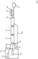
- Fig. 1 shows a schematic representation of an arrangement for determining the operating state of the circuit breaker 10.
- a circuit breaker 10 is usually used with a closed housing in a switchgear and comprises mechanical components such as a motor, springs, shafts, shock absorbers and buffers.
- the mechanical components When the circuit breaker 10 is in operation, the mechanical components cause vibrations and/or sound signals that are emitted into the entire environment. Further vibrations or sound signals are caused by mains voltage (for example 50 Hz hum or 100 Hz hum or hum of other mains frequencies) or by external sources such as running machines in the vicinity of the circuit breaker 10.
- mains voltage for example 50 Hz hum or 100 Hz hum or hum of other mains frequencies
- An experienced maintenance technician can determine the operating state of the circuit breaker 10 solely on the basis of the noise generated when the springs are tensioned and when a switching operation is triggered.
- the present method enables, in particular, automated determination and analysis of the operating state. In addition to the processes perceptible to the human ear, other operating states can be determined.
- Sensors 11a, 11b, 11c are arranged in or near the circuit breaker 10 for this purpose.
- the sensors 11a, 11b, 11c are each able to record vibrations, structure-borne sound or airborne sound and work according to a suitable physical principle.
- Piezo microphones, condenser microphones, structure-borne sound sensors, fiber-optic sound sensors or fiber-optic vibration sensors can be used as sensors 11a, 11b, 11c, for example.
- Analog measurement signals 12a, 12b, 12c from the sensors 11a, 11b, 11c then undergo analog preprocessing 13, in which the analog measurement signals 12a, 12b, 12c are amplified if necessary and/or run through an anti-aliasing filter.
- an analog-digital conversion 14 of the analog measurement signals 12a, 12b, 12c whereby a single analog-digital converter can be used in a multiplexing process or several analog-digital converters can be used in a parallel process.
- the digitized measurement signals are then processed in an evaluation device 15 by one or more processors (for example by a CPU, a microprocessor, an embedded system, a digital signal processor or another special processor), by one or more programmable logic components (for example a complex programmable logic device, CPLD or a field programmable gate array, FPGA) or by a full Custom chip processed.
- An operating state of the circuit breaker 10 is then determined and a result is generated and output in an output device 16 and/or passed to a network 17.
- the output device 16 comprises, for example, an LED or a display.
- a maintenance technician can use this to call up details of the measurements and/or the operating status.
- a single sensor is sufficient for the process.
- the number of vibration and sound sensors 11a, 11b, 11c installed influences the quality of the condition assessment.
- the signal-to-noise ratio with which the measurement signals 12a, 12b, 12c are recorded can in principle be improved.
- the frequency bandwidth with which vibration signals and/or sound signals 12a, 12b, 12c are recorded can be increased by combining the frequency bands of different sensors 11a, 11b, 11c.
- the infrasound emitted by vibrations can be recorded in parallel with ultrasound with moderate effort.
- the use of multiple sensors 11a, 11b, 11c also enables the localization of sources responsible for the vibration and/or sound signals using transit time measurements. This is important because the location of a vibration and/or sound event can also be used to identify the cause of the respective event. If a vibration and/or sound event can be localized during a switch-on process, for example, near a buffer responsible for the switch-on process, the sound is likely to have been generated by the shaft hitting the buffer.
- the measurement signals 12a, 12b, 12c not only to assess the functionality of the circuit breaker 10 as a whole, but also to assess the functionality of the buffer, the reliability of the operating state analysis can be improved and made more precise.
- the assignment of the cause for a vibration signal and/or sound signal 12a, 12b, 12c can be determined by taking into account control signals that trigger actions on the circuit breaker 10. trigger, can be improved. If, for example, springs are tensioned using a motor, the motor must be supplied with power.
- a motor signal 12d by tapping a motor-starting control signal and/or a measurement on a power supply line of the motor can be used by the evaluation device 15 to assign the resulting vibrations and sound emissions to the motor or another component involved.
- Fig. 2 shows a schematic representation of the method for determining the operating state of the circuit breaker 10.
- the generated digital signals are processed algorithmically as explained below. In principle, fewer or more than three input channels are possible. This is in Fig. 3 represented by dots between elements 21b and 21c to 24a and 24c.
- variations of the algorithms and the order in which the algorithms are executed are possible.
- the algorithms can be implemented as hardware and/or software.
- a digital preprocessing 22a, 22b, 22c of the digital signals takes place in a first processing step.
- the measurement data of each individual sensor 11a, 11b, 11c is processed separately.
- This processing step is optional, but particularly advantageous if the measurement signals 12a, 12b, 12c are permeated by interference signals (noise) that are of no importance for the operating state analysis. In the vicinity of the circuit breaker 10, very noisy measurement signals 12a, 12b, 12c will generally occur.
- noise reduction methods such as low-pass filters, notch filters or wavelets are suitable.
- the digital signals can be related to each other.
- cross-channel digital signal preprocessing 23a, 23b, 23c takes place. This enables a further improvement in the signal-to-noise ratio.
- the vibration and sound signals 12a, 12b, 12c caused by different signal sources on the circuit breaker 10 can also be separated and assigned to different sources. For example, if a switching process is triggered and vibrations are caused simultaneously by a spring and a buffer, two separate signals can be calculated using runtime effects, of which one signal is exclusively assigned to the spring and the other signal exclusively to the buffer. The separation of the individual signals considerably simplifies the operating state analysis of the circuit breaker 10.
- the preprocessed signals are categorized.
- the aim of this processing step is to transform the preprocessed signals in such a way that only those state characteristics remain that reliably enable an assessment of the operating state of the circuit breaker 10.
- the signals from different channels can be combined, 24a, or obtained from a single channel, 24c.
- signal processing methods such as (short-time) Fourier transformation, wavelet transformation and/or template matching can be used. In simple cases, it may be sufficient to determine the state characteristics directly by evaluating the preprocessed signals, for example by determining the envelope curves of the respective signals.
- temporal information 26 is used to increase the reliability of the determination of the operating state.
- a second Classification unit 27 determines that the operating state of the circuit breaker 10 changes in small steps over time.
- results comprising, for example, the operating state of the circuit breaker 10 and/or an analysis result of an analysis of the operating state undergo a result processing 28.
- motor signal 12d is initially available in analog form, it is subjected to an analog-to-digital conversion 29. The motor signal 12d can then be included and processed when the second to sixth processing steps are carried out.
- the results can be sent directly to a user via the network 17.
- the input data and the results can be visualized in tabular form, as graphs or diagrams, by listing probabilities and presented via the output device 16.
- the maintenance personnel can use the input device 18 to call up details of the measurements and/or the operating status.
- circuit breakers 10 it is possible to automatically monitor the mechanics of circuit breakers 10 and to arrive at an assessment of their operating status. In the event of problems occurring spontaneously, this can prevent the circuit breaker 10 from having to be taken out of service for a longer period of time (because, for example, a defect leads to the destruction of the circuit breaker 10) or from having to be taken out of service at all (for example, in the event of damage that allows the circuit breaker to continue to operate for a short period of time).
- circuit breakers 10 Since appropriately equipped circuit breakers 10 are permanently monitored, routine checks can either be omitted entirely or maintenance intervals can be extended compared to conventional circuit breakers 10. This saves costs. It is possible to retrofit a diagnostic system for permanent operating status analysis to existing circuit breakers 10. To carry out the operating status analysis of circuit breakers 10, it is not necessary to remove or decommission them. Normal maintenance on circuit breakers 10 requires their removal or at least their decommissioning and intervention in the control of the circuit breaker 10. This is not necessary if the method described here is used.
- the method enables the use of a simple and cost-effective embedded system as well as suitable, cost-effective, conventional sensors 11a, 11b, 11c.
- the manufacture of a correspondingly equipped circuit breaker 10 is therefore hardly more expensive than that of a conventional circuit breaker. At the same time, however, considerable added value is achieved. In particular, remote maintenance and monitoring are possible and therefore offer considerable potential for savings in terms of maintenance and repair costs, since the condition of the circuit breaker 10 can be continuously monitored.
- the electronics and sensors can be installed in circuit breakers in a way that does not require any changes to safety-critical components. Contact with low, medium or high voltage components is also not required. When using fiber optic sensors, contact with medium and high voltage components is possible, for example. The technology can also be retrofitted without great effort.
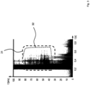
- Fig. 3 shows a schematic representation of a spectrogram determined by means of a short-time Fourier transformation based on measurement signals during a switch-off process of a circuit breaker 10, which were recorded with a fiber optic microphone.
- a quotient of power and frequency Plf is plotted against runtime t and frequency f .
- Higher values of Plf are colored dark.
- Fig. 4 shows a schematic representation of a spectrogram based on measurement signals during a switching-off process of the circuit breaker 10, wherein the angle of rotation of the switching shaft of the circuit breaker 10 was changed during the measurements.
- FIG. 5 shows a schematic representation of a spectrogram based on measurement signals during the switching-off process of the circuit breaker 10, whereby a shock absorber with a modified damping characteristic was used.
- the areas within the dashed lines 31, 41, 51 in the Fig. 3 to 5 show how the individual modifications are reflected in the acoustic emissions and thus in the spectrogram.
- the dotted lines 32, 42, 52 delimit a range of maximum amplitudes of the respective frequency. A change in the respective amplitude of a frequency component is significant for a certain state of the circuit breaker.
- the time of occurrence of a specific frequency component and the amplitude in Fig. 5 represented by the intensity of the blackening, suitable as a classification feature.
- the dashed lines 31, 41, 51 each show an area that is relevant and suitable for determining the state of the circuit breaker and contains features to be classified.
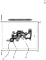
- Fig. 7 shows a further schematic representation of a spectrogram based on measurement signals from acoustic sensors attached to switch poles during a switch-on process of the circuit breaker 10 with a reduced switching stroke of about 10 mm.
- a pulse 71 of the switch-on coil is followed by a pulse 72 at the switch-on time and then a pulse 73 at the latching time.
- Fig. 7 the change in the temporal resolution of the spectrogram with a reduced switching stroke from 13 mm to 10 mm. If a closing spring in the circuit breaker 10 is set in motion by the triggering of a closing mechanism in accordance with the impulse of the closing coil, contact elements in a switch pole first meet. This is followed by mechanical latching so that the switch remains switched on.
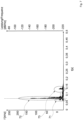
- Fig. 8 and 9 each show a spectral frequency distribution over time, determined on the basis of a wavelet analysis, during a switch-on process with different settings of the switching stroke of the circuit breaker 10. Areas of medium amplitude are colored dark, areas of low and high amplitude are colored light. Fig. 8 The switching stroke was increased during the corresponding switching process and the Fig. 9 The switching stroke of one pole is increased, maintained or reduced respectively during the corresponding switching-on process.
- the data on the new state of the circuit breaker 10 is determined as reference data (corresponding to an acoustic vibration fingerprint of the circuit breaker 10), the data can be used as a basis to determine contact wear. If contact wear occurs on a switch pole, the switching times of the circuit breaker 10 change. The contact elements close at a different time than in the original state. At the same time, wear on each individual switching pole can be determined from the different switching times by comparing the individual switching times for each switch pole. The switching time of each individual switch pole can therefore be measured, which allows statements to be made about the wear on the contacts of switch poles, mechanics, or switching speeds and thus about the mechanical function of the drive system and the triggering of closing and opening coils.
- This representation also shows whether the circuit breaker 10 has switched at all and/or whether the switching times or movement sequences of the circuit breaker 10 have changed. This is particularly important because a non-switching circuit breaker must be replaced in its function by other circuit breakers that are in operation.
- Data such as the Fig. 3 to 9 enable statements to be made, for example, regarding the opening of a contact of a switch pole; the speed of closing a contact; the sequence of closing contacts; the time delay between individual contact points; the wear status and/or degree of wear of a contact; the speed of a rotary movement of a switching shaft; the success of a switching on and/or off process; the drive energy for a motor winding in a spring-loaded drive; the question of whether a spring is wound up or relaxed and/or whether an unrecorded, abnormal frequency spectrum is present; a tripping process of a closing magnet; a release process of locking pawls; a switching success of a breaking magnet; a drive shaft starting to run loose, a latch engaging, a storage drive functioning, a magnitude of rotary movements of the switching shaft; an end position of the switching shaft being reached; a change in a characteristic and/or a need to replace a stop damper; an energy conversion of a spring drive system in the circuit breaker; or
- Fiber optic sensors 11a, 11b, 11c are preferred here, as they can also be attached to high-voltage switch poles and can thus obtain meaningful measurement data on the state of each individual switch pole at the source.
- Attaching them to a housing of a drive mechanism of the circuit breaker 10 also allows statements to be made about the state of the circuit breaker 10, whether a mechanism of the circuit breaker 10 is moving properly or whether changes are occurring, for example due to resinous greases, which lead to a change in switching times.
- the use of fiber optic sensors is not limited to one type of circuit breaker or one variant. There are also no restrictions with regard to the voltage level or the switching capability of the circuit breaker 10.
- the application of the method described has the significant advantage that an operating state analysis and continuous monitoring are possible by simply attaching the sensors 11a, 11b, 11c to the circuit breaker 10. In contrast to previous analyses of circuit breakers, this means that intervention in the circuit breaker 10 is not necessary. The circuit breaker 10 does not have to be taken out of operation and no intervention in the control of the circuit breaker 10 is necessary. This eliminates long downtimes of the circuit breaker 10 during which it is not available.
Landscapes
- Physics & Mathematics (AREA)
- General Physics & Mathematics (AREA)
- Arc-Extinguishing Devices That Are Switches (AREA)
Claims (14)
- Procédé de détermination d'un état de fonctionnement d'un équipement électrique comportant un élément de commutation, comprenant :- la détection de signaux de mesure (12a, 12b, 12c) pour un équipement électrique comportant un élément de commutation au moyen d'un dispositif de capteur, qui présente un capteur, dans lequel les signaux de mesure (12a, 12b, 12c) pour l'équipement électrique comprennent au moins un type de signaux de mesure (12a, 12b, 12c) du groupe suivant : signaux vibratoires et signaux sonores ;- le traitement des signaux de mesure (12a, 12b, 12c) au moyen d'un dispositif d'évaluation (15), dans lequel le traitement comprend une conversion analogique-numérique (14) des signaux de mesure (12a, 12b, 12c) en signaux de mesure numériques ; et- la détermination d'un état de fonctionnement de l'équipement électrique à partir d'un groupe d'états de fonctionnement différents utilisant le dispositif d'évaluation (15), dans lequel les signaux de mesure numériques sont comparés à des signaux de comparaison dont chacun est associé à au moins un des différents états de fonctionnement,dans lequella comparaison des signaux numériques de mesure avec les signaux de comparaison comprend une classification automatisée de l'état de fonctionnement,caractérisé en ce queles signaux de mesure (12a, 12b, 12c) sont détectés à l'aide d'un capteur à fibre optique (11a, 11b, 11c).
- Procédé selon la revendication 1, caractérisé en ce que les signaux de mesure (12a, 12b, 12c) comprennent à la fois des signaux vibratoires et des signaux sonores.
- Procédé selon la revendication 1 ou 2, caractérisé en ce que les signaux de mesure (12a, 12b, 12c) sont détectés à l'aide de plusieurs capteurs (11a, 11b, 11c).
- Procédé selon au moins une des revendications précédentes, caractérisé en ce que les signaux sonores (12a, 12b, 12c) comprennent au moins un type de signaux sonores (12a, 12b, 12c) du groupe suivant : signaux infrasonores, signaux sonores auditifs et signaux ultrasonores.
- Procédé selon une au moins des revendications précédentes, caractérisé en ce que- l'état de fonctionnement d'un équipement électrique est déterminé à l'intérieur et/ou à l'extérieur d'un appareillage ; et/ou- l'état de fonctionnement est déterminé pour un équipement électrique, qui transporte de la haute ou de la basse tension.
- Procédé selon une au moins des revendications précédentes, caractérisé en ce que les signaux de mesure (12a, 12b, 12c) sont prétraités lors du traitement, ce qui permet d'augmenter le rapport signal/bruit des signaux de mesure (12a, 12b, 12c).
- Procédé selon la revendication 6, caractérisé en ce que les signaux de mesure (12a, 12b, 12c) sont prétraités analogiquement au moyen d'au moins un du groupe : filtre passe-bas, filtre passe-haut, filtres passe-bande et filtre anti-repliement.
- Procédé selon la revendication 6 ou 7, caractérisé en ce que les signaux de mesure (12a, 12b, 12c) sont prétraités numériquement au moyen d'au moins un du groupe : filtre coupe-bande, analyse par ondelettes, transformation de Fourier discrète, transformation de Fourier rapide et à court terme.
- Procédé selon au moins une des revendications précédentes, caractérisé en ce que lors de la détermination de l'état de fonctionnement, au moins une caractéristique d'état caractérisant l'état de fonctionnement de l'équipement électrique est déterminée d'après les signaux de mesure numériques.
- Procédé selon la revendication 9, caractérisé en ce que la au moins une caractéristique d'état est déterminée en utilisant au moins un membre du groupe transformation de Fourier, transformation de Fourier à court terme, transformation en ondelettes, concordance de modèle, spectrogramme et enveloppe.
- Procédé selon la revendication 9 ou 10, caractérisé en ce que l'état de fonctionnement de l'équipement électrique est déterminé en classifiant au moins une caractéristique d'état à l'aide d'au moins un procédé de classification automatisé.
- Procédé selon la revendication 11, caractérisé en ce que le procédé de classification automatisé est entraîné à l'aide des signaux de comparaison avant la mise en oeuvre du procédé et/ou pendant le fonctionnement.
- Procédé selon une au moins des revendications 9 à 12, caractérisé en ce que une évolution temporelle de l'état de fonctionnement de l'équipement électrique et/ou de la ou des caractéristiques d'état est déterminée.
- Agencement, comportant :- un équipement électrique, qui présente un élément de commutation ;- un dispositif de capteur qui possède un capteur et est configuré pour recevoir des signaux de mesure (12a, 12b, 12c) pour détecter l'équipement électrique, dans lequel les signaux de mesure (12a, 12b, 12c) pour l'équipement électrique comprennent au moins un type de signaux de mesure (12a, 12b, 12c) du groupe suivant : signaux vibratoires et signaux sonores ; et- un dispositif d'évaluation (15) qui est conçu pour- traiter les signaux de mesure (12a, 12b, 12c), dans lequel le traitement comprend une conversion analogique-numérique (14) des signaux de mesure (12a, 12b, 12c) en signaux de mesure numériques ; et- déterminer un état de fonctionnement pour l'équipement électrique à partir d'un groupe d'états de fonctionnement différents, dans lequel dans ce cadre les signaux numériques de mesure sont comparés à des signaux de comparaison qui sont chacun affectés à au moins un des différents états de fonctionnement,dans lequel la comparaison des signaux numériques de mesure avec les signaux de comparaison comprend une classification automatisée de l'état de fonctionnement,caractérisé en ce quele capteur est un capteur à fibre optique (11a, 11b, 11c).
Applications Claiming Priority (2)
| Application Number | Priority Date | Filing Date | Title |
|---|---|---|---|
| DE102018124210.7A DE102018124210A1 (de) | 2018-10-01 | 2018-10-01 | Verfahren zum Bestimmen eines Betriebszustands für ein elektrisches Betriebsmittel mit einem Schalterelement |
| PCT/DE2019/100859 WO2020069698A1 (fr) | 2018-10-01 | 2019-09-27 | Procédé pour déterminer un état de fonctionnement pour un matériel électrique muni d'un élément commutateur |
Publications (3)
| Publication Number | Publication Date |
|---|---|
| EP3861307A1 EP3861307A1 (fr) | 2021-08-11 |
| EP3861307C0 EP3861307C0 (fr) | 2024-12-04 |
| EP3861307B1 true EP3861307B1 (fr) | 2024-12-04 |
Family
ID=68290132
Family Applications (1)
| Application Number | Title | Priority Date | Filing Date |
|---|---|---|---|
| EP19790122.6A Active EP3861307B1 (fr) | 2018-10-01 | 2019-09-27 | Procédé pour déterminer un état de fonctionnement pour un matériel électrique muni d'un élément commutateur |
Country Status (3)
| Country | Link |
|---|---|
| EP (1) | EP3861307B1 (fr) |
| DE (1) | DE102018124210A1 (fr) |
| WO (1) | WO2020069698A1 (fr) |
Families Citing this family (5)
| Publication number | Priority date | Publication date | Assignee | Title |
|---|---|---|---|---|
| DE102020119012B4 (de) | 2020-07-17 | 2022-05-19 | Hochschule Für Technik Und Wirtschaft Berlin | Vorrichtung und Verfahren zum Bestimmen einer Ladungsstärke einer Teilentladung |
| CN113390452B (zh) * | 2021-06-16 | 2023-08-18 | 北京康斯特仪表科技股份有限公司 | 一种开关型仪表校准方法及装置 |
| FR3133670A1 (fr) * | 2022-06-14 | 2023-09-22 | Sagemcom Broadband Sas | Auto-diagnostic d’un équipement électrique par empreinte sonore |
| US12592316B2 (en) | 2022-08-04 | 2026-03-31 | Fresenius Medical Care Holdings, Inc. | Diagnostic methods and systems using sound detection |
| CN115856599A (zh) * | 2022-11-09 | 2023-03-28 | 中国南方电网有限责任公司 | 一种刀闸分合状态判别方法、装置、系统及设备 |
Citations (1)
| Publication number | Priority date | Publication date | Assignee | Title |
|---|---|---|---|---|
| US20150233792A1 (en) * | 2012-05-31 | 2015-08-20 | Canrig Drilling Technology | Methods and Apparatuses for Defect Diagnosis in a Mechanical System |
Family Cites Families (6)
| Publication number | Priority date | Publication date | Assignee | Title |
|---|---|---|---|---|
| US4980844A (en) * | 1988-05-27 | 1990-12-25 | Victor Demjanenko | Method and apparatus for diagnosing the state of a machine |
| US8054594B2 (en) * | 2009-06-18 | 2011-11-08 | General Electric Company | ARC flash detection system |
| DE102010061605A1 (de) * | 2010-12-28 | 2012-06-28 | Bundesanstalt für Materialforschung und -Prüfung (BAM) | Faseroptischer Sensor sowie Messeinrichtung mit einem faseroptischen Sensor |
| US20120197546A1 (en) * | 2011-01-27 | 2012-08-02 | General Electric Company | Method, system and computer program product to identify a physical event using a vibration signature |
| WO2015100577A1 (fr) * | 2013-12-31 | 2015-07-09 | Siemens Aktiengesellschaft | Dispositifs et procédés de détection de défaut d'arc |
| US10533978B2 (en) * | 2015-08-13 | 2020-01-14 | Eaton Intelligent Power Limited | Vibration sensor assembly for prognostic and diagnostic health assessment of a power circuit breaker's power transmission and distribution system in real time |
-
2018
- 2018-10-01 DE DE102018124210.7A patent/DE102018124210A1/de not_active Withdrawn
-
2019
- 2019-09-27 EP EP19790122.6A patent/EP3861307B1/fr active Active
- 2019-09-27 WO PCT/DE2019/100859 patent/WO2020069698A1/fr not_active Ceased
Patent Citations (1)
| Publication number | Priority date | Publication date | Assignee | Title |
|---|---|---|---|---|
| US20150233792A1 (en) * | 2012-05-31 | 2015-08-20 | Canrig Drilling Technology | Methods and Apparatuses for Defect Diagnosis in a Mechanical System |
Also Published As
| Publication number | Publication date |
|---|---|
| EP3861307C0 (fr) | 2024-12-04 |
| WO2020069698A1 (fr) | 2020-04-09 |
| DE102018124210A1 (de) | 2020-04-02 |
| EP3861307A1 (fr) | 2021-08-11 |
Similar Documents
| Publication | Publication Date | Title |
|---|---|---|
| EP3861307B1 (fr) | Procédé pour déterminer un état de fonctionnement pour un matériel électrique muni d'un élément commutateur | |
| EP2730906B1 (fr) | Dispositif et procédé de surveillance de l'état d'un palier à roulement | |
| DE60221149T2 (de) | System und verfahren zur identifikation des vorhandenseins von defekten in einer vibrierenden maschine | |
| DE102008025596B4 (de) | Verfahren zum Betrieb einer Einrichtung | |
| EP2409398B1 (fr) | Dispositif pour surveiller des commutateurs à gradins | |
| EP3891518B1 (fr) | Système et procédé de détection d'usure d'un dispositif de commutation électromécanique | |
| EP3763031B1 (fr) | Système, procédé et programme informatique pour la détection de grandeurs physiques d'au moins un composant d'un transformateur à changement de prises et pour la surveillance des composants d'un transformateur à changement de prises | |
| CH696646A5 (de) | Verfahren zur Analyse und/oder Überwachung des Teilentladungsverhaltens eines elektrischen Betriebsmittels. | |
| CN110320467A (zh) | 一种低压直流断路器故障诊断方法 | |
| DE102008029087A1 (de) | Überwachungssystem für ein Schwingungen unterworfenes Aggregat | |
| EP2718681A2 (fr) | Procédé et dispositif pour surveiller les vibrations de tête de bobine d'un générateur | |
| WO1993003530A1 (fr) | Procede et dispositif de reconnaissance de defauts dans des systemes convertisseurs | |
| EP2697880A1 (fr) | Procédé destiné à générer un signal d'erreur | |
| DE102018127457A1 (de) | Vorrichtung und Verfahren zur Zustandsüberwachung einer elektrischen Maschine | |
| DE102018003625A1 (de) | Zustandsüberwachungsverfahren und -system für elektrische Leistungskomponenten,... | |
| DE102021006389B3 (de) | Verfahren zur automatischen Erstellung von anlagenspezifischen Messprofilen für ein Isolationsüberwachungssystem | |
| DE10062606A1 (de) | Verfahren und Einrichtung zum Überwachen des mechanischen Zustands von elektrisch angetriebenen Fahrzeugen im regulären Fahrbetrieb | |
| WO2022096525A1 (fr) | Système de capteur | |
| DE102015210911A1 (de) | Verfahren und Vorrichtung zum Erkennen von Veränderungen in einem elektrisch betriebenen Antrieb | |
| DE102020135173A1 (de) | Diagnosevorrichtung für eine Überwachung einer Kenngröße an einer elektrischen Hochspannungskomponente, Messanordnung und Verfahren zum Auswerten von Messsignalen | |
| DE102020114222A1 (de) | Antrieb für eine elektrische Anwendung und Verfahren zur Aufrechterhaltung und Feinabstimmung des Antriebs | |
| DE112022006856T5 (de) | Ausrüstungsdiagnoseeinrichtung und ausrüstungsdiagnosesystem | |
| EP4682553A1 (fr) | Procédé d'analyse de l'état d'un convertisseur d'énergie électromécanique et système | |
| DE102021109102B3 (de) | Verfahren zur Überwachung eines Vorrichtungszustands einer Vorrichtung; System | |
| DE102019125873A1 (de) | Verfahren sowie sensor- und auswerteinrichtung zur dezentralen ermittlung von diagnoseinformationen über elektrische verbraucher einer maschinenanlage |
Legal Events
| Date | Code | Title | Description |
|---|---|---|---|
| STAA | Information on the status of an ep patent application or granted ep patent |
Free format text: STATUS: UNKNOWN |
|
| STAA | Information on the status of an ep patent application or granted ep patent |
Free format text: STATUS: THE INTERNATIONAL PUBLICATION HAS BEEN MADE |
|
| PUAI | Public reference made under article 153(3) epc to a published international application that has entered the european phase |
Free format text: ORIGINAL CODE: 0009012 |
|
| STAA | Information on the status of an ep patent application or granted ep patent |
Free format text: STATUS: REQUEST FOR EXAMINATION WAS MADE |
|
| 17P | Request for examination filed |
Effective date: 20210324 |
|
| AK | Designated contracting states |
Kind code of ref document: A1 Designated state(s): AL AT BE BG CH CY CZ DE DK EE ES FI FR GB GR HR HU IE IS IT LI LT LU LV MC MK MT NL NO PL PT RO RS SE SI SK SM TR |
|
| DAV | Request for validation of the european patent (deleted) | ||
| DAX | Request for extension of the european patent (deleted) | ||
| STAA | Information on the status of an ep patent application or granted ep patent |
Free format text: STATUS: EXAMINATION IS IN PROGRESS |
|
| 17Q | First examination report despatched |
Effective date: 20230217 |
|
| GRAP | Despatch of communication of intention to grant a patent |
Free format text: ORIGINAL CODE: EPIDOSNIGR1 |
|
| STAA | Information on the status of an ep patent application or granted ep patent |
Free format text: STATUS: GRANT OF PATENT IS INTENDED |
|
| INTG | Intention to grant announced |
Effective date: 20240301 |
|
| RIN1 | Information on inventor provided before grant (corrected) |
Inventor name: KOELLING, MORITZ Inventor name: MENGE, MATTHIAS Inventor name: GRAEF, THOMAS |
|
| GRAJ | Information related to disapproval of communication of intention to grant by the applicant or resumption of examination proceedings by the epo deleted |
Free format text: ORIGINAL CODE: EPIDOSDIGR1 |
|
| STAA | Information on the status of an ep patent application or granted ep patent |
Free format text: STATUS: EXAMINATION IS IN PROGRESS |
|
| GRAP | Despatch of communication of intention to grant a patent |
Free format text: ORIGINAL CODE: EPIDOSNIGR1 |
|
| STAA | Information on the status of an ep patent application or granted ep patent |
Free format text: STATUS: GRANT OF PATENT IS INTENDED |
|
| INTC | Intention to grant announced (deleted) | ||
| INTG | Intention to grant announced |
Effective date: 20240715 |
|
| GRAS | Grant fee paid |
Free format text: ORIGINAL CODE: EPIDOSNIGR3 |
|
| GRAA | (expected) grant |
Free format text: ORIGINAL CODE: 0009210 |
|
| STAA | Information on the status of an ep patent application or granted ep patent |
Free format text: STATUS: THE PATENT HAS BEEN GRANTED |
|
| REG | Reference to a national code |
Ref country code: DE Ref legal event code: R081 Ref document number: 502019012612 Country of ref document: DE Owner name: HOCHSCHULE FUER TECHNIK UND WIRTSCHAFT BERLIN,, DE Free format text: FORMER OWNER: ANMELDERANGABEN UNKLAR / UNVOLLSTAENDIG, 80297 MUENCHEN, DE |
|
| AK | Designated contracting states |
Kind code of ref document: B1 Designated state(s): AL AT BE BG CH CY CZ DE DK EE ES FI FR GB GR HR HU IE IS IT LI LT LU LV MC MK MT NL NO PL PT RO RS SE SI SK SM TR |
|
| REG | Reference to a national code |
Ref country code: CH Ref legal event code: EP |
|
| REG | Reference to a national code |
Ref country code: DE Ref legal event code: R096 Ref document number: 502019012612 Country of ref document: DE |
|
| REG | Reference to a national code |
Ref country code: IE Ref legal event code: FG4D Free format text: LANGUAGE OF EP DOCUMENT: GERMAN |
|
| U01 | Request for unitary effect filed |
Effective date: 20241211 |
|
| U07 | Unitary effect registered |
Designated state(s): AT BE BG DE DK EE FI FR IT LT LU LV MT NL PT RO SE SI Effective date: 20250114 |
|
| PG25 | Lapsed in a contracting state [announced via postgrant information from national office to epo] |
Ref country code: HR Free format text: LAPSE BECAUSE OF FAILURE TO SUBMIT A TRANSLATION OF THE DESCRIPTION OR TO PAY THE FEE WITHIN THE PRESCRIBED TIME-LIMIT Effective date: 20241204 |
|
| PG25 | Lapsed in a contracting state [announced via postgrant information from national office to epo] |
Ref country code: ES Free format text: LAPSE BECAUSE OF FAILURE TO SUBMIT A TRANSLATION OF THE DESCRIPTION OR TO PAY THE FEE WITHIN THE PRESCRIBED TIME-LIMIT Effective date: 20241204 |
|
| PG25 | Lapsed in a contracting state [announced via postgrant information from national office to epo] |
Ref country code: NO Free format text: LAPSE BECAUSE OF FAILURE TO SUBMIT A TRANSLATION OF THE DESCRIPTION OR TO PAY THE FEE WITHIN THE PRESCRIBED TIME-LIMIT Effective date: 20250304 |
|
| PG25 | Lapsed in a contracting state [announced via postgrant information from national office to epo] |
Ref country code: GR Free format text: LAPSE BECAUSE OF FAILURE TO SUBMIT A TRANSLATION OF THE DESCRIPTION OR TO PAY THE FEE WITHIN THE PRESCRIBED TIME-LIMIT Effective date: 20250305 |
|
| PG25 | Lapsed in a contracting state [announced via postgrant information from national office to epo] |
Ref country code: RS Free format text: LAPSE BECAUSE OF FAILURE TO SUBMIT A TRANSLATION OF THE DESCRIPTION OR TO PAY THE FEE WITHIN THE PRESCRIBED TIME-LIMIT Effective date: 20250304 |
|
| PG25 | Lapsed in a contracting state [announced via postgrant information from national office to epo] |
Ref country code: SM Free format text: LAPSE BECAUSE OF FAILURE TO SUBMIT A TRANSLATION OF THE DESCRIPTION OR TO PAY THE FEE WITHIN THE PRESCRIBED TIME-LIMIT Effective date: 20241204 |
|
| PG25 | Lapsed in a contracting state [announced via postgrant information from national office to epo] |
Ref country code: PL Free format text: LAPSE BECAUSE OF FAILURE TO SUBMIT A TRANSLATION OF THE DESCRIPTION OR TO PAY THE FEE WITHIN THE PRESCRIBED TIME-LIMIT Effective date: 20241204 |
|
| PG25 | Lapsed in a contracting state [announced via postgrant information from national office to epo] |
Ref country code: IS Free format text: LAPSE BECAUSE OF FAILURE TO SUBMIT A TRANSLATION OF THE DESCRIPTION OR TO PAY THE FEE WITHIN THE PRESCRIBED TIME-LIMIT Effective date: 20250404 |
|
| PG25 | Lapsed in a contracting state [announced via postgrant information from national office to epo] |
Ref country code: SK Free format text: LAPSE BECAUSE OF FAILURE TO SUBMIT A TRANSLATION OF THE DESCRIPTION OR TO PAY THE FEE WITHIN THE PRESCRIBED TIME-LIMIT Effective date: 20241204 |
|
| PG25 | Lapsed in a contracting state [announced via postgrant information from national office to epo] |
Ref country code: CZ Free format text: LAPSE BECAUSE OF FAILURE TO SUBMIT A TRANSLATION OF THE DESCRIPTION OR TO PAY THE FEE WITHIN THE PRESCRIBED TIME-LIMIT Effective date: 20241204 |
|
| PLBE | No opposition filed within time limit |
Free format text: ORIGINAL CODE: 0009261 |
|
| STAA | Information on the status of an ep patent application or granted ep patent |
Free format text: STATUS: NO OPPOSITION FILED WITHIN TIME LIMIT |
|
| U20 | Renewal fee for the european patent with unitary effect paid |
Year of fee payment: 7 Effective date: 20250923 |
|
| 26N | No opposition filed |
Effective date: 20250905 |