EP3861801B1 - Appareil, procédé et programme informatique - Google Patents
Appareil, procédé et programme informatique Download PDFInfo
- Publication number
- EP3861801B1 EP3861801B1 EP18783456.9A EP18783456A EP3861801B1 EP 3861801 B1 EP3861801 B1 EP 3861801B1 EP 18783456 A EP18783456 A EP 18783456A EP 3861801 B1 EP3861801 B1 EP 3861801B1
- Authority
- EP
- European Patent Office
- Prior art keywords
- data signals
- slot
- transmission phase
- user equipment
- direct transmission
- Prior art date
- Legal status (The legal status is an assumption and is not a legal conclusion. Google has not performed a legal analysis and makes no representation as to the accuracy of the status listed.)
- Active
Links
Images



Classifications
-
- H—ELECTRICITY
- H04—ELECTRIC COMMUNICATION TECHNIQUE
- H04L—TRANSMISSION OF DIGITAL INFORMATION, e.g. TELEGRAPHIC COMMUNICATION
- H04L5/00—Arrangements affording multiple use of the transmission path
- H04L5/003—Arrangements for allocating sub-channels of the transmission path
- H04L5/0037—Inter-user or inter-terminal allocation
-
- H—ELECTRICITY
- H04—ELECTRIC COMMUNICATION TECHNIQUE
- H04L—TRANSMISSION OF DIGITAL INFORMATION, e.g. TELEGRAPHIC COMMUNICATION
- H04L5/00—Arrangements affording multiple use of the transmission path
- H04L5/003—Arrangements for allocating sub-channels of the transmission path
- H04L5/0053—Allocation of signalling, i.e. of overhead other than pilot signals
-
- H—ELECTRICITY
- H04—ELECTRIC COMMUNICATION TECHNIQUE
- H04B—TRANSMISSION
- H04B7/00—Radio transmission systems, i.e. using radiation field
- H04B7/02—Diversity systems; Multi-antenna system, i.e. transmission or reception using multiple antennas
- H04B7/022—Site diversity; Macro-diversity
- H04B7/026—Co-operative diversity, e.g. using fixed or mobile stations as relays
-
- H—ELECTRICITY
- H04—ELECTRIC COMMUNICATION TECHNIQUE
- H04W—WIRELESS COMMUNICATION NETWORKS
- H04W52/00—Power management, e.g. Transmission Power Control [TPC] or power classes
- H04W52/04—Transmission power control [TPC]
- H04W52/30—Transmission power control [TPC] using constraints in the total amount of available transmission power
- H04W52/34—TPC management, i.e. sharing limited amount of power among users or channels or data types, e.g. cell loading
- H04W52/346—TPC management, i.e. sharing limited amount of power among users or channels or data types, e.g. cell loading distributing total power among users or channels
-
- H—ELECTRICITY
- H04—ELECTRIC COMMUNICATION TECHNIQUE
- H04W—WIRELESS COMMUNICATION NETWORKS
- H04W88/00—Devices specially adapted for wireless communication networks, e.g. terminals, base stations or access point devices
- H04W88/02—Terminal devices
- H04W88/04—Terminal devices adapted for relaying to or from another terminal or user
Definitions
- the present application relates to a method, apparatus, system and computer program.
- a wireless communication system can be seen as a facility that enables communication sessions.
- the session may be between two or more entities.
- the entity or entities may be user terminals, machine type devices and/or the like.
- the entity or entities may be an access node such as a base station and/or the like.
- At least a part of a communication session occurs over a wireless link.
- Non-orthogonal multiple access allows access by different communication devices in the same resources.
- An electronic device may comprise apparatus as described herein.
- a chipset may comprise apparatus as described herein.
- Embodiments of the present application aim to address problems associated with the state of the art.
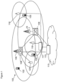
- a wireless communication system 100 such as that shown in figure 1
- mobile communication devices or user equipment (UE) 102, 104, 105 are provided wireless access via at least one base station or similar wireless transmitting and/or receiving node or point.
- Base stations are typically controlled by at least one appropriate controller apparatus, so as to enable operation thereof and management of mobile communication devices in communication with the base stations.
- the controller apparatus may be located in a radio access network (e.g. wireless communication system 100) or in a core network (CN) (not shown) and may be implemented as one central apparatus or its functionality may be distributed over several apparatuses.
- the controller apparatus may be part of the base station and/or provided by a separate entity such as a Radio Network Controller.
- control apparatus 108 and 109 are shown to control the respective macro level base stations 106 and 107.
- the control apparatus of a base station can be interconnected with other control entities.
- the control apparatus is typically provided with memory capacity and at least one data processor.
- the control apparatus and functions may be distributed between a plurality of control units. In some systems, the control apparatus may additionally or alternatively be provided in a radio network controller.
- base stations 106 and 107 are shown as connected to a wider communications network 113 via gateway 112.
- a further gateway function may be provided to connect to another network.
- the smaller base stations 116, 118 and 120 may also be connected to the network 113, for example by a separate gateway function and/or via the controllers of the macro level stations.
- the base stations 116, 118 and 120 may be pico or femto level base stations or the like. In the example, stations 116 and 118 are connected via a gateway 111 whilst station 120 connects via the controller apparatus 108. In some embodiments, the smaller stations may not be provided. Smaller base stations 116, 118 and 120 may be part of a second network, for example WLAN and may be WLAN APs.
- the communication devices 102, 104, 105 may access the communication system based on various access techniques, such as code division multiple access (CDMA), or wideband CDMA (WCDMA).
- CDMA code division multiple access
- WCDMA wideband CDMA
- Other non-limiting examples comprise time division multiple access (TDMA), frequency division multiple access (FDMA) and various schemes thereof such as the interleaved frequency division multiple access (IFDMA), single carrier frequency division multiple access (SC-FDMA) and orthogonal frequency division multiple access (OFDMA), space division multiple access (SDMA) and so on.
- TDMA time division multiple access
- FDMA frequency division multiple access
- IFDMA interleaved frequency division multiple access
- SC-FDMA single carrier frequency division multiple access
- OFDMA orthogonal frequency division multiple access
- SDMA space division multiple access
- LTE Long Term Evolution
- UMTS Universal Mobile Telecommunications System
- LTE-A LTE Advanced
- E-UTRAN Evolved Universal Terrestrial Radio Access Network
- EPC Evolved Packet Core
- Base stations of such systems are known as evolved or enhanced Node Bs (eNBs) and provide E-UTRAN features.
- eNBs evolved or enhanced Node Bs
- Some embodiments may be provided in the context so call 5G or NR (new radio) network architecture. However, it should be appreciated that this is by way of example and other embodiments may be implemented in the context of other network architectures.
- a basic multiple access scheme which is orthogonal for one or both of downlink and uplink data transmissions.
- This may be referred to as orthogonal multiple access (OMA).
- OMA orthogonal multiple access
- resources of different users can be differentiated.
- the resources may be physical resources such as time and/or frequency which are not overlapped.
- the signals for different users may alternatively or additionally be differentiated using one or more of the spatial domain and the coding domain.
- non-orthogonal multiple-access (NOMA) schemes may alternatively or additionally be used.
- signals from two or more UEs might be transmitted simultaneously in the same resources, e.g., time domain resources and frequency domain resources.
- this non-orthogonal interference characteristic may be more pronounced.
- transmitter side schemes such as spreading (linear or non-linear, with or without sparseness) and/or interleaving may be employed. This may improve the performance of the system. Alternatively or additionally, this may ease the burden of advanced receivers.
- Non-orthogonal multiple access may be beneficial for grant-free transmission. This may be due to the availability of plenty of NOMA signatures and/or the correspondingly low multiple access (MA) signature collision rate for grant-free transmissions.
- the NOMA signature may be one or more of a: spreading sequence of a specific spreading factor; a scrambling sequence; and an interleaving pattern.
- Non-orthogonal multiple access may have more than one user or communication device served in each orthogonal resource block, e.g., a time slot, a frequency channel, a spreading code, or an orthogonal spatial degree of freedom.
- NOMA may be advantageous in various use cases or deployment scenarios.
- NOMA may be deployed in one or more of enhanced mobile broad band (eMBB), ultra-reliable low latency communication (URLLC) and massive machine type communication (mMTC).
- eMBB enhanced mobile broad band
- URLLC ultra-reliable low latency communication
- mMTC massive machine type communication
- NOMA may use less signalling than OMA. This may result in one or more of: reducing a UE's power consumption; reducing latency; and increasing system capacity.
- a possible mobile communication device will now be described in more detail with reference to Figure 2 showing a schematic, partially sectioned view of a communication device 200.
- a communication device is often referred to as user equipment (UE) or terminal.
- An appropriate mobile communication device may be provided by any device capable of sending and receiving radio signals.
- Non-limiting examples comprise a mobile station (MS) or mobile device such as a mobile phone or what is known as a 'smart phone', a computer provided with a wireless interface card or other wireless interface facility (e.g., USB dongle), personal data assistant (PDA) or a tablet provided with wireless communication capabilities, machine-type communications MTC devices, loT type communication devices or any combinations of these or the like.
- the communications may be one or more of voice, electronic mail (email), text message, multimedia, data, machine data, sensor data, etc.
- a mobile device is typically provided with at least one data processing entity 201, at least one memory 202 and other possible components 203 for use in software and hardware aided execution of tasks it is designed to perform, including control of access to and communications with access systems and other communication devices.
- the data processing, storage and other relevant control apparatus can be provided on an appropriate circuit board and/or in chipsets. This feature is denoted by reference 204.
- the user may control the operation of the mobile device by means of a suitable user interface such as key pad 205, voice commands, touch sensitive screen or pad, combinations thereof or the like.
- a display 208, a speaker and a microphone can be also provided.
- a mobile communication device may comprise appropriate connectors (either wired or wireless) to other devices and/or for connecting external accessories, for example hands-free equipment, thereto.
- the mobile device 200 may receive signals over an air or radio interface 207 via appropriate apparatus for receiving and may transmit signals via appropriate apparatus for transmitting radio signals.
- transceiver apparatus is designated schematically by block 206.
- the transceiver apparatus 206 may be provided for example by means of a radio part and associated antenna arrangement.
- the antenna arrangement may be arranged internally or externally to the mobile device.
- Figure 3 shows an example of a control apparatus for an access system, such as a RAN node, e.g. a base station, eNB or gNB, a relay node.
- the method as discussed herein may be implanted in a single control apparatus or across more than one control apparatus.
- the control apparatus may be integrated with or external to a node or module of a core network or RAN.
- base stations comprise a separate control apparatus unit or module.
- the control apparatus can be another network element such as a radio network controller or a spectrum controller.
- each base station may have such a control apparatus as well as a control apparatus being provided in a radio network controller.
- the control apparatus 300 comprises at least one memory 301, at least one data processing unit 302, 303 and an input/output interface 304. Via the interface the control apparatus can be coupled to a receiver and a transmitter of the base station.
- the receiver and/or the transmitter may be implemented as a radio front end or a remote radio head.
- Non-Orthogonal Multiple Access is one of the promising techniques to overcome the problem of resource scarcity.
- NOMA supports simultaneous connections of multiple users with the same channel, and has the advantages of high spectral efficiency, massive connectivity, low latency, and high user fairness.
- cooperative NOMA has been proposed to take full advantage of the prior information that users with better channel conditions have about other users' messages.
- nodes there are envisioned to be many power-constrained nodes within loT systems which are hard to charge in a conventional manner. These nodes may be located off the power grid and without a suitable long term power source or not able to be serviced. Such nodes may suffer from a short lifespans if, using significant transmission power, they are required to transmit signals to far users. Therefore, energy harvesting has attracted much research attention.
- the receive time period is divided into two sub-slots.
- the embodiments as discussed herein feature a cooperative Non-Orthogonal Multiple Access (C-NOMA) scheme, where a near user (UE 1) is configured to harvest energy from the signals sent from a suitable access point, for example a base station, and relay a decoded message of far user (UE 2).
- C-NOMA Non-Orthogonal Multiple Access
- the transmission from the BS can be divided into two phases: a transmission phase (Phase 1) and a cooperative transmission phase (Phase 2).
- Phase 1 is defined as two time slots, lasting for t and 1-t, respectively.
- UE 1 harvests energy only in the first slot (t) and receives both information and energy simultaneously in the second slot (1-t), while UE 2 receives information during the whole phase.
- the UE 1 since UE 1 has already decoded UE 2's data before decoding its own through successive interference cancellation during Phase 1 (based on a suitable NOMA scheme), the UE 1 then is configured to use the energy harvested to transmit the decoded data to UE 2 during the cooperative transmission phase (Phase 2).
- t is defined as a first tuneable parameter (variable) which can be adjusted in order to attempt to achieve an 'optimal' performance.
- UE 1 is configured to divides the received power during Phase 1 into two parts, one for energy harvesting, the other for signal decoding, where we denote the proportion of first part by p, and second part by 1-p.
- p is a second tuneable parameter (variable) which can be adjusted for optimal performance.
- UE 1 is configured to relay the decoded message to UE 2. Then UE 2 is configured to combine the signals received in the two phases using a suitable method, for example maximal ratio combining (MRC).
- MRC maximal ratio combining
- the proposed scheme has a substantial gain over the conventional NOMA scheme without cooperation.
- One advantage of the proposed scheme is that devices that are not being blocked can serve as relays to help the BS to reach those devices and reduce the probability of user outage.
- the energy harvesting scheme falls back into conventional NOMA, which means the embodiments will not cause unnecessary extra energy consumption and the data rate of UE 1 is not jeopardized.
- the cooperative transmission and energy harvesting is turned on when necessary and off when not needed.
- FIG. 4 With respect to Figure 4 is shown an example flow diagram showing the downlink transmission implementation of the system according to some embodiments.
- the access point or base station (BS) 402 which is transmitting to a first mobile communications device, a near UE (UE 1) 404, and a second mobile communications device, a far UE (UE 2) 406.
- UE 1 near UE
- UE 2 far UE
- BS base station
- the downlink transmission period is shown comprising two phases.
- the two phases comprise a first phase 400 which is also known as a direct transmission phase (Phase 1), a second phase 450 which is also known as a cooperative transmission phase (Phase 2).
- the direct transmission phase 400 may be defined (normalized) with the total time length of 1.
- the BS is configured to directly transmit to UE 1 and UE 2.
- the direct transmission phase 400 (phase 1) comprises two time slots, lasting for t and 1-t, respectively.
- the base station 402 is configured to transmit a signal for the UE 2 406 for the duration t (or slot) as shown in Figure 4 by step 401.
- the base station 402 is then configured to transmit both a signal for the UE 1 404 and a signal for the UE 2 406 for the duration 1-t (or slot) as shown in Figure 4 by step 403.
- phase 1 ends for the base station 402 as shown in Figure 4 by step 405.
- the UE 1 404 is configured to harvest energy from the base station transmitted signal as shown in Figure 4 by step 411. The harvested energy is then going to be used for relaying data in phase 2.
- duration 1-t UE 1 404 is then configured to receive the radio signal and divide the power received from the base station transmitted signal into two parts p, and 1-p as shown in Figure 4 by step 413.
- the UE 1 404 is configured to harvest energy from the base station transmitted signal first part p as shown in Figure 4 by step 417. This harvested energy may then be combined with the harvested energy from the duration t.
- the UE 1 404 is also configured to use the second part 1-p of the base station transmitted signal for the duration 1-t and decode any data associated with UE 1 404 and furthermore any data associated with UE 2 406.
- the decoding may be performed using any suitable method, for example, successive interference cancelation (SIC) as shown in Figure 4 by step 415.
- SIC successive interference cancelation
- the decoded data associated with UE 1 may be processed and the decoded data associated with UE 2 is then passed to a transmitter.
- the UE 2 406 is configured to decode data associated with the UE 2, from the base station transmitted signal as shown in Figure 4 by step 421.
- duration 1-t UE 2 406 is then configured to receive the radio signal from the base station but does not decode any data from the signal at this time as shown in Figure 4 by step 423.
- the UE 1 404 is configured to transmit (or forward) the data associated with UE 2 406 (decoded during step 415) using the summed harvested energy (harvested by step 411 and 417) as shown in Figure 4 by step 418.
- the transmission may be implemented using an out-of-band channel to support the device-to-device (D2D) communication between UE 1 and UE 2.
- D2D device-to-device
- the UE 2 406 is configured to receive the transmitted signal from UE 1 404 and combine the signal with the earlier received signal from the base station (received by step 423), for example using maximum-ratio combining (MRC). Having combined the signal the UE 2 406 is configured to decode the data associated with UE 2 406 as shown in Figure 4 by step 425.
- MRC maximum-ratio combining
- FIG. 5a With respect to Figure 5a is shown a schematic representation of an example apparatus suitable for implementing a near mobile communications device UE 1 404.
- the UE 1 404 in some embodiments comprises a receiver 501 (or receiver part of a suitable transceiver module) configured to receive the signals transmitted from the base station or any suitable access point.
- the signals may be passed to a switch 503.
- the UE 1 404 in some embodiments further comprises a switch 503.
- the switch 503 is configured to receive the signals from the receiver 501 and furthermore receive a suitable control signal from a controller 505 indicating the time duration t (and therefore 1-t) and the portion p (and therefore 1-p) parameters with respect to the direct transmission phase, phase 1.
- the switch is configured to control the outputting of the signals to an energy harvester 507 and to an information decoder 509 based on the parameters and as discussed herein.
- the UE 1 404 in some embodiments further comprises an energy harvester 507.
- the energy harvester 507 is configured to receive the signals from the switch 503 and furthermore receive a suitable control signal from a controller 505 indicating the time duration t (and therefore 1-t) and the portion p (and therefore 1-p) parameters with respect to the direct transmission phase, phase 1.
- the energy harvester 507 is configured to harvest or scrape energy from the received signals and use the energy to power a transmitter 511 as discussed herein.
- the UE 1 404 in some embodiments further comprises an information decoder 509.
- the information decoder 509 is configured to receive the signals from the switch 503 and furthermore receive a suitable control signal from a controller 505 indicating the time duration t (and therefore 1-t) and the portion p (and therefore 1-p) parameters with respect to the direct transmission phase, phase 1.
- the information decoder 509 is configured to decode the far mobile communications device UE 2 data and pass this to the transmitter 511 and furthermore to decode the near mobile communications device UE 1 data which may be processed in any suitable manner.
- the UE 1 404 in some embodiments further comprises a transmitter 511 (or transmitter part of a suitable transceiver module).
- the transmitter 511 is configured to receive the decoded data associated with UE 2 from the information decoder 509 and energy from the energy harvester 507 and using this energy transmit the data associated with UE 2 to the UE 2 in the co-operative transmission phase (phase 2) in a manner such as described herein.
- the UE 1 404 in some embodiments further comprises a controller 505.
- the controller 505 is configured to control the switch 503, information decoder 509, energy harvester 507 and transmitter 511 using the control signal from a controller 505 indicating the time duration t (and therefore 1-t) and the portion p (and therefore 1-p) parameters with respect to the direct transmission phase, phase 1 and during the co-operative transmission phase (phase 2) in a manner such as described herein.
- FIG. 5b With respect to Figure 5b is shown a schematic representation of an example apparatus suitable for implementing a far mobile communications device UE 2 406.
- the schematic representation of an example apparatus suitable for implementing a far mobile communications device UE 2 406 is a subset of the schematically shown components of the representation of an example apparatus suitable for implementing a near mobile communications device UE 1 404 shown in Figure 5a .
- a generic mobile communications device may be employed as a near mobile communications device UE 1 404 and/or a far mobile communications device UE 2 406.
- the generic mobile communications device may be defined as being near or far based on the received signal strength from the access point.
- the UE 2 406 in some embodiments comprises a receiver 551 (or receiver part of a suitable transceiver module) configured to receive the signals transmitted from the base station or any suitable access point and from UE 1.
- the signals may be passed to an information controller 555 (and via in some embodiments a switch not shown for clarity).
- the UE 2 406 in some embodiments further comprises an information decoder 555.
- the information decoder 555 is configured to receive the signals from the receiver 501 and furthermore receive a suitable control signal from a controller 553 indicating the time duration t (and therefore 1-t) and the portion p (and therefore 1-p) parameters with respect to the direct transmission phase, phase 1.
- the information decoder 509 is configured to combine the received signals and decode the far mobile communications device UE 2 data as described herein.
- the UE 2 406 in some embodiments further comprises a controller 553.
- the controller 553 is configured to control the information decoder 555 using the control signal indicating the time duration t (and therefore 1-t) and the portion p (and therefore 1- ⁇ ) parameters with respect to the direct transmission phase, phase 1 and during the co-operative transmission phase (phase 2) in a manner such as described herein.
- the UE 1 404 is configured to harvest energy only in the first slot and receives both information and energy simultaneously in the second slot, while UE 2 just receives information during the whole phase. Therefore, during the first slot, the BS transmits signal of UE 2 only, while the superposition of UE 1's and UE 2's signals is transmitted in the second slot. Since UE 1 has already decoded UE 2's data before decoding its own through SIC during Phase 1, it then uses the energy scraped up to transmit the decoded data to UE 2 during cooperative transmission phase (Phase 2).
- the signal sent by the BS during Phase 1 can be generally denoted by P 1 1 j x 1 + P 2 1 j x 2
- P 1 1 j is the power allocated to UE i in a j th time slot
- the superscript '1' indicates Phase 1 (similar subscripts and superscripts are applied to data rate R, signal-to-noise ratio or signal-to-noise-plus-interference ratio ⁇ too).
- the maximal transmitted power of the BS is P T and x 1 and x 2 are the messages for UE 1 and UE 2, respectively.
- h i denotes the channel link gain from the BS to UE i
- n i is the additive white Gaussian noise (AWGN) with zero mean and variance ⁇ 2 .
- AWGN additive white Gaussian noise
- UE 1 divides the received power P 1 1 2 into two parts, one for energy harvesting, the other for signal decoding.
- the UE 2 does not decode its data at this stage. Instead, it will be decoded after combining with the signals received in Phase 2.
- Phase 2 UE 1 relays the decoded message x k to UE 2. Then UE 2 is configured to combine the signals received in the two phases using maximal ratio combining (MRC) or other suitable combining method.
- MRC maximal ratio combining
- the total power consumption for cooperative transmission P C should satisfy 1 ⁇ t P C ⁇ E H
- the rate may be, R 2 MRC ⁇ log 2 1 + h 1 2 1 ⁇ ⁇ P 2 1 2 h 1 2 1 ⁇ ⁇ P 1 1 2 + ⁇ 2
- the controller may be configured to attempt to determine parameters such that it produces a maximal R 2 MRC under a certain R 1 value.
- UE 2's data reception comprises of two parts.
- the first part is from the BS during the first slot of Phase 1
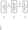
- the system parameters r are determined as shown in Figure 6 by step 601.
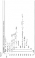
- a first comparison 704 is performed to determine whether 1 ⁇ t log 2 1 + h 1 2 1 ⁇ ⁇ P T ⁇ 2 ⁇ r . Where it is then the inner loop continues 705 otherwise the inner loop passes to the next iteration (it ends 706).
- the next operation is the calculation of a temporary R 2 value according to t log 2 1 + h 2 2 P T ⁇ 2 + 1 ⁇ t R 2 MRC as shown in step 707.
- the next operation is a comparison of the temporary R 2 value to the current stored R 2 value as shown in step 708.
- the current stored R 2 value is set as the temporary R 2 value as shown in step 709.
- the inner loop repeats (ends) as shown in step 711.
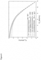
- the conventional NOMA scheme which has no cooperation phase is also shown 807.
- the cooperative schemes outperform conventional NOMA and the plot of power splitting scheme 803 matches the example embodiment generalized scheme 801 as discussed above. Both of them are better than time switching scheme 805 with the improvement being more obvious when R 1 is small.
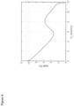
- FIG. 9 a plot of the performance gain in R 2 of the example embodiments scheme over conventional NOMA.
- the largest gain is around 10%.
- R 1 is too large, there is no gain at all. From Figure 9 it can be seen that the gain does not decrease all the way when R 1 increases. Instead, it oscillates up and down before going to zero.
- a target rate for UE 1 can be set to around 8 to achieve the local maximum, which is a good trade-off between R1 and R2, whereas R1 in the leftmost part of the figure is too low although the gain on R2 is high.
- FIG. 10 a plot of the gain of the example embodiments scheme over conventional NOMA and the channel condition of UE 2 from BS.
- Figure 10 shows the result.
- the channel between the BS and UE 2 is totally blocked, the only way to reach UE 2 is by relaying through UE 1.
- UE 2 cannot be reached when
- 2 0.
- the proposed scheme becomes extremely important.
- 2 is as good as
- One advantage of the example embodiments scheme is that other devices that are not being blocked can serve as relays to help the BS to reach those devices and reduce user outage probability. Note that when the above scenario does not happen, the energy harvesting scheme falls back into conventional NOMA, which means it may not cost unnecessary extra energy consumption and the data rate of UE 1 will not be jeopardized. In other words, the cooperative transmission and energy harvesting is turned on when necessary and off when not needed.
- the various embodiments of the invention may be implemented in hardware or special purpose circuits, software, logic or any combination thereof.
- some aspects may be implemented in hardware, while other aspects may be implemented in firmware or software which may be executed by a controller, microprocessor or other computing device, although the invention is not limited thereto.
- firmware or software which may be executed by a controller, microprocessor or other computing device, although the invention is not limited thereto.
- While various aspects of the invention may be illustrated and described as block diagrams, flow charts, or using some other pictorial representation, it is well understood that these blocks, apparatus, systems, techniques or methods described herein may be implemented in, as non-limiting examples, hardware, software, firmware, special purpose circuits or logic, general purpose hardware or controller or other computing devices, or some combination thereof.
- the embodiments of this invention may be implemented by computer software executable by a data processor of the mobile device, such as in the processor entity, or by hardware, or by a combination of software and hardware.
- any blocks of the logic flow as in the Figures may represent program steps, or interconnected logic circuits, blocks and functions, or a combination of program steps and logic circuits, blocks and functions.
- the software may be stored on such physical media as memory chips, or memory blocks implemented within the processor, magnetic media such as hard disk or floppy disks, and optical media such as for example DVD and the data variants thereof, CD.
- the memory may be of any type suitable to the local technical environment and may be implemented using any suitable data storage technology, such as semiconductor-based memory devices, magnetic memory devices and systems, optical memory devices and systems, fixed memory and removable memory.
- the data processors may be of any type suitable to the local technical environment, and may include one or more of general purpose computers, special purpose computers, microprocessors, digital signal processors (DSPs), application specific integrated circuits (ASIC), gate level circuits and processors based on multi-core processor architecture, as non-limiting examples.
- Embodiments of the inventions may be practiced in various components such as integrated circuit modules.
- the design of integrated circuits is by and large a highly automated process.
- Complex and powerful software tools are available for converting a logic level design into a semiconductor circuit design ready to be etched and formed on a semiconductor substrate.
- Programs such as those provided by Synopsys, Inc. of Mountain View, California and Cadence Design, of San Jose, California automatically route conductors and locate components on a semiconductor chip using well established rules of design as well as libraries of pre-stored design modules.
- the resultant design in a standardized electronic format (e.g., Opus, GDSII, or the like) may be transmitted to a semiconductor fabrication facility or "fab" for fabrication.
Landscapes
- Engineering & Computer Science (AREA)
- Signal Processing (AREA)
- Computer Networks & Wireless Communication (AREA)
- Mobile Radio Communication Systems (AREA)
Claims (10)
- Appareil (402) comprenant des moyens pour :
contrôler une transmission de l'appareil (402) à au moins deux équipements utilisateurs (404 ; 406) au sein d'un système de communication (100), dans lequel les moyens pour contrôler une transmission de l'appareil (402) à au moins deux équipements utilisateurs (404 ; 406) au sein d'un système de communication (100) sont en outre destinés à :
contrôler une transmission de signaux de données pour un équipement utilisateur (406) des au moins deux équipements utilisateurs (404 ; 406) pour un premier créneau d'une phase de transmission directe (400) de l'appareil (402) aux au moins deux équipements utilisateurs (404 ; 406) au sein du système de communication (100), de sorte que :ledit un équipement utilisateur (406) des au moins deux équipements utilisateurs (404 ; 406) soit configuré pour recevoir et décoder les signaux de données ; etau moins un autre équipement utilisateur (404) des au moins deux équipements utilisateurs (404 ; 406) soit configuré pour recevoir et récolter l'énergie à partir des signaux de données pour relayer des signaux de données audit un équipement utilisateur (406) des au moins deux équipements utilisateurs (404 ; 406) pour une phase de transmission coopérative (450) ;contrôler une transmission de signaux de données à la fois pour ledit un équipement utilisateur (406) des au moins deux équipements utilisateurs et ledit au moins un autre équipement utilisateur (404) des au moins deux équipements utilisateurs (404 ; 406) pour un deuxième créneau d'une phase de transmission directe (400) de l'appareil (402) aux au moins deux équipements utilisateurs (404 ; 406) au sein du système de communication (100), de sorte que :
l'au moins un autre équipement utilisateur (404) des au moins deux équipements utilisateurs (404 ; 406) soit configuré pour recevoir et diviser les signaux de données en deux parties :une première partie à partir de laquelle l'au moins un autre équipement utilisateur (404) des au moins deux équipements utilisateurs (404 ; 406) est configuré pour récolter l'énergie pour relayer des signaux de données audit un équipement utilisateur (406) des au moins deux équipements utilisateurs (404 ; 406) ; etune deuxième partie à partir de laquelle l'au moins un autre équipement utilisateur (404) des au moins deux équipements utilisateurs (404 ; 406) est configuré pour décoder des données pour l'au moins un autre équipement utilisateur (404) des au moins deux équipements utilisateurs (404 ; 406) et décoder des données pour relayer des signaux de données audit un équipement utilisateur (406) des au moins deux équipements utilisateurs (404 ; 406) dans la phase de transmission coopérative (450) en utilisant l'énergie récoltée,dans lequel les moyens sont en outre destinés à obtenir des valeurs pour le premier créneau et le deuxième créneau de la phase de transmission directe (400), dans lequel les moyens pour obtenir des valeurs pour le premier créneau et le deuxième créneau de la phase de transmission directe (400) sont en outre destinés à effectuer au moins l'une des opérations suivantes :déterminer un paramètre temporel t pour définir une longueur du premier créneau et du deuxième créneau de la phase de transmission directe (400) ;déterminer un paramètre de portion p pour définir la première partie à partir de laquelle l'au moins un autre équipement utilisateur (404) des au moins deux équipements utilisateurs (404 ; 406) est configuré pour récolter l'énergie pour relayer des signaux de données audit un équipement utilisateur (406) des au moins deux équipements utilisateurs (404 ; 406), et pour définir la deuxième partie à partir de laquelle l'au moins un autre équipement utilisateur (404) des au moins deux équipements utilisateurs (404 ; 406) est configuré pour décoder des données pour l'au moins un autre équipement utilisateur (404) des au moins deux équipements utilisateurs (404 ; 406) et décoder des données pour relayer des signaux de données audit un équipement utilisateur (406) des au moins deux équipements utilisateurs (404 ; 406) dans la phase de transmission coopérative (450) en utilisant l'énergie récoltée ;déterminer conjointement le paramètre temporel et le paramètre de portion ; ourecevoir le paramètre temporel et le paramètre de portion d'un appareil supplémentaire, dans lequelle paramètre temporel et le paramètre de portion sont déterminés sur la base de paramètres de voie de communication mesurés entre l'appareil (402), ledit un équipement utilisateur (406) des au moins deux équipements utilisateurs (404 ; 406) et ledit au moins un autre équipement utilisateur (404) des au moins deux équipements utilisateurs (404 ; 406). - Appareil (402) selon la revendication 1, dans lequel les moyens pour contrôler une transmission de signaux de données à la fois pour ledit un équipement utilisateur (406) des au moins deux équipements utilisateurs (404 ; 406) et ledit au moins un autre équipement utilisateur (404) des au moins deux équipements utilisateurs (404 ; 406) sont en outre destinés à une transmission d'accès multiple non orthogonal de signaux de données à la fois pour ledit un équipement utilisateur (406) des au moins deux équipements utilisateurs (404 ; 406) et ledit au moins un autre équipement utilisateur (404) des au moins deux équipements utilisateurs (404 ; 406).
- Appareil (404) comprenant des moyens pour :pour un premier créneau d'une phase de transmission directe (400), recevoir (501) d'un point d'accès (402) des signaux de données pour un appareil (406) supplémentaire ;récolter l'énergie (507) à partir des signaux de données pour relayer des signaux de données à l'appareil (406) supplémentaire dans une phase de transmission coopérative (450) ;pour un deuxième créneau d'une phase de transmission directe (400), recevoir (501) du point d'accès des signaux de données à la fois pour l'appareil (406) supplémentaire et l'appareil (404) ;diviser (503) les signaux de données à la fois pour l'appareil (406) supplémentaire et l'appareil (404) en deux parties ;récolter l'énergie (507) à partir d'une première partie des deux parties des signaux de données reçus à la fois pour l'appareil (406) supplémentaire et l'appareil (404) pour relayer des signaux de données à l'appareil (406) supplémentaire dans une phase de transmission coopérative (450) ;à partir d'une deuxième partie des deux parties des signaux de données reçus à la fois pour l'appareil (406) supplémentaire et l'appareil (404), décoder (509) des données pour l'appareil (404) et pour l'appareil (406) supplémentaire ; etdans la phase de transmission coopérative (450) suivant la phase de transmission directe (400), relayer (511) à l'appareil (406) supplémentaire les données décodées pour l'appareil (406) supplémentaire en utilisant l'énergie récoltée à partir du premier créneau et du deuxième créneau,dans lequel les moyens sont en outre destinés à obtenir des valeurs pour :un paramètre temporel t pour définir une longueur du premier créneau et du deuxième créneau de la phase de transmission directe (400) ; etun paramètre de portion p pour définir la première partie et la deuxième partie du deuxième créneau, dans lequelles moyens pour obtenir des valeurs sont en outre destinés à effectuer au moins l'une des opérations suivantes :déterminer le paramètre temporel t et le paramètre de portion p ; etrecevoir le paramètre temporel t et le paramètre de portion p d'un appareil supplémentaire,dans lequel les moyens pour déterminer le un paramètre temporel t et le paramètre de portion p sont en outre destinés à déterminer conjointement le paramètre temporel t et le paramètre de portion p ;dans lequel le paramètre temporel t et le paramètre de portion p sont déterminés sur la base de paramètres de voie de communication mesurés entre l'appareil (404), l'appareil (406) supplémentaire et un point d'accès (402).
- Appareil (404) selon la revendication 3, dans lequel les moyens pour recevoir du point d'accès (402), pour un deuxième créneau d'une phase de transmission directe (400), des signaux de données à la fois pour l'appareil (406) supplémentaire et l'appareil (404) sont en outre destinés à recevoir des signaux d'accès multiple non orthogonal, et les moyens de décodage sont en outre destinés à des interférences système annulant les signaux d'accès multiple non orthogonal.
- Appareil (404) selon l'une des revendications 3 ou 4, dans lequel une durée de la phase de transmission coopérative (450) suivant la phase de transmission directe (400) est sensiblement la même qu'une durée du deuxième créneau de la phase de transmission directe (400).
- Appareil (404) selon l'une des revendications 3 à 5, dans lequel les moyens de relai sont en outre destinés à relayer les données décodées pour l'appareil (406) supplémentaire en utilisant l'énergie récoltée à partir des premier et deuxième créneaux en utilisant un canal hors bande.
- Appareil (406) comprenant des moyens pour :pour un premier créneau d'une phase de transmission directe (400), recevoir (551) d'un point d'accès (402) des signaux de données pour l'appareil (406) ;décoder (555) le premier créneau de signaux de données de phase de transmission directe ;pour un deuxième créneau d'une phase de transmission directe (400), recevoir (551) du point d'accès (402) des signaux de données à la fois pour l'appareil (406) et un appareil (404) supplémentaire ;recevoir (551) de l'appareil (404) supplémentaire des signaux de données pour l'appareil (406) dans une phase de transmission coopérative (450) suivant la phase de transmission directe (400) ;combiner les signaux de données à la fois pour l'appareil (406) et un appareil (404) supplémentaire provenant du point d'accès (402) et les signaux de données pour l'appareil (406) provenant de l'appareil (404) supplémentaire ; etdécoder (555) les signaux de données combinés,dans lequel les moyens sont en outre destinés à obtenir des valeurs pour :un paramètre temporel t pour définir une longueur du premier créneau et du deuxième créneau de la phase de transmission directe ; etun paramètre de portion p pour définir la première partie et la deuxième partie du deuxième créneau, dans lequelles moyens pour obtenir les valeurs sont en outre destinés à effectuer au moins l'une des opérations suivantes :déterminer le paramètre temporel t et le paramètre de portion p ; etrecevoir le paramètre temporel t et le paramètre de portion p d'un appareil supplémentaire,dans lequel les moyens pour déterminer le paramètre temporel t et le paramètre de portion p sont en outre destinés à déterminer conjointement le paramètre temporel t et le paramètre de portion p ;dans lequel le paramètre temporel t et le paramètre de portion p sont déterminés sur la base de paramètres de voie de communication mesurés entre l'appareil (406), l'appareil (404) supplémentaire et un point d'accès (402).
- Appareil (406) selon la revendication 7, dans lequel les moyens pour recevoir du point d'accès (402), pour un deuxième créneau d'une phase de transmission directe (400), des signaux de données à la fois pour l'appareil (404) supplémentaire et l'appareil (406) sont en outre destinés à recevoir des signaux d'accès multiple non orthogonal, et les moyens pour recevoir de l'appareil (404) supplémentaire des signaux de données pour l'appareil (406) dans une phase de transmission coopérative (450) suivant la phase de transmission directe (400) sont en outre destinés à recevoir des signaux de données en utilisant un canal hors bande.
- Appareil (406) selon l'une des revendications 7 ou 8, dans lequel des moyens pour combiner les signaux de données à la fois pour l'appareil (406) et un appareil (404) supplémentaire provenant du point d'accès (402) et les signaux de données pour l'appareil (406) provenant de l'appareil (404) supplémentaire sont en outre destinés à une combinaison à rapport maximal.
- Appareil (406) selon l'une des revendications 7 à 9, dans lequel une durée de la phase de transmission coopérative (450) suivant la phase de transmission directe (400) est sensiblement la même qu'une durée du deuxième créneau de la phase de transmission directe (400).
Applications Claiming Priority (1)
| Application Number | Priority Date | Filing Date | Title |
|---|---|---|---|
| PCT/EP2018/077207 WO2020069761A1 (fr) | 2018-10-05 | 2018-10-05 | Appareil, procédé et programme informatique |
Publications (2)
| Publication Number | Publication Date |
|---|---|
| EP3861801A1 EP3861801A1 (fr) | 2021-08-11 |
| EP3861801B1 true EP3861801B1 (fr) | 2025-06-25 |
Family
ID=63799004
Family Applications (1)
| Application Number | Title | Priority Date | Filing Date |
|---|---|---|---|
| EP18783456.9A Active EP3861801B1 (fr) | 2018-10-05 | 2018-10-05 | Appareil, procédé et programme informatique |
Country Status (4)
| Country | Link |
|---|---|
| US (1) | US11476900B2 (fr) |
| EP (1) | EP3861801B1 (fr) |
| CN (1) | CN112840710A (fr) |
| WO (1) | WO2020069761A1 (fr) |
Families Citing this family (6)
| Publication number | Priority date | Publication date | Assignee | Title |
|---|---|---|---|---|
| EP3970305A1 (fr) * | 2019-05-17 | 2022-03-23 | IDAC Holdings, Inc. | Procédés et appareil de collecte et de signalisation d'énergie de liaison montante |
| CN111918320B (zh) * | 2020-07-14 | 2022-05-24 | 吉林大学 | 时分双工下非正交多址接入的无线通信资源优化分配方法 |
| CN112737656A (zh) * | 2020-12-16 | 2021-04-30 | 中国人民解放军战略支援部队信息工程大学 | 基于非正交多址技术的中继网络绿色安全传输方法及系统 |
| TWI796896B (zh) * | 2021-12-23 | 2023-03-21 | 國立高雄師範大學 | 基於認知無線電網路的多重存取控制方法 |
| CN115915206B (zh) * | 2022-11-03 | 2025-06-10 | 西安电子科技大学 | 无线供能通信网络中eMBB和URLLC的复用方法 |
| CN116647914B (zh) * | 2023-05-19 | 2024-01-02 | 山东大学 | 基于能量收集的交替协作非正交多址接入方法及装置 |
Family Cites Families (13)
| Publication number | Priority date | Publication date | Assignee | Title |
|---|---|---|---|---|
| EP2095530B1 (fr) * | 2006-12-20 | 2016-02-17 | Nokia Technologies Oy | Appareil, procédé et produit de programme d'ordinateur fournissant un facteur de gain de liaison montante pour un accès par paquet de liaison montante haute vitesse |
| WO2014047253A1 (fr) * | 2012-09-19 | 2014-03-27 | Duke University | Transfert d'énergie sans fil miso et mimo par abonnement |
| EP3327983A1 (fr) * | 2014-09-11 | 2018-05-30 | NTT DoCoMo, Inc. | Station de base, équipement d'utilisateur et système de radio communication |
| US10411856B2 (en) * | 2014-10-27 | 2019-09-10 | Qualcomm Incorporated | Reference signal and transmit power ratio design for non-orthogonal transmissions |
| CN105119865B (zh) * | 2015-07-21 | 2018-10-02 | 南方科技大学 | 数字信能同传接收方法及系统 |
| WO2017117253A1 (fr) * | 2015-12-30 | 2017-07-06 | Idac Holdings, Inc. | Procédés, systèmes, et dispositifs permettant une coopération d'unité de transmission/réception sans fil |
| KR102233218B1 (ko) * | 2016-01-19 | 2021-03-29 | 삼성전자주식회사 | 무선 통신 시스템에서 모바일 기기가 통신 가능한 적어도 하나의 기기를 제어하는 방법 및 모바일 기기 |
| WO2017160723A1 (fr) * | 2016-03-15 | 2017-09-21 | Northeastern University | Système et procédé de charge sans fil distribuée |
| TWI628969B (zh) * | 2017-02-14 | 2018-07-01 | 國立清華大學 | 聯合用戶分組與功率分配方法以及使用所述方法的基地台 |
| CN107105470A (zh) * | 2017-03-29 | 2017-08-29 | 西安电子科技大学 | 一种携能协作cr‑noma协作模式和中继选择算法 |
| CN107911166B (zh) * | 2017-11-14 | 2020-04-24 | 山东大学 | 一种基于无线能量收割与非正交多址的可见光/射频混合协作通信方法 |
| CN108512585B (zh) * | 2018-04-04 | 2020-07-24 | 哈尔滨工业大学 | 基于功率域非正交多址接入技术的动态协作中继传输方法 |
| US11751284B2 (en) * | 2020-09-24 | 2023-09-05 | Qualcomm Incorporated | Cooperative relay in sidelink networks |
-
2018
- 2018-10-05 EP EP18783456.9A patent/EP3861801B1/fr active Active
- 2018-10-05 CN CN201880098436.5A patent/CN112840710A/zh active Pending
- 2018-10-05 US US17/280,260 patent/US11476900B2/en active Active
- 2018-10-05 WO PCT/EP2018/077207 patent/WO2020069761A1/fr not_active Ceased
Also Published As
| Publication number | Publication date |
|---|---|
| US20220045722A1 (en) | 2022-02-10 |
| US11476900B2 (en) | 2022-10-18 |
| CN112840710A (zh) | 2021-05-25 |
| EP3861801A1 (fr) | 2021-08-11 |
| WO2020069761A1 (fr) | 2020-04-09 |
Similar Documents
| Publication | Publication Date | Title |
|---|---|---|
| EP3861801B1 (fr) | Appareil, procédé et programme informatique | |
| US12471121B2 (en) | Sidelink communication method and terminal device | |
| CN110391887B (zh) | 信号处理方法及装置 | |
| US11398890B2 (en) | Unified non-orthogonal multiple access | |
| US20090279478A1 (en) | Method and apparatus for facilitating dynamic cooperative interference reduction | |
| US20240372668A1 (en) | Method for determining frequency-domain resource position, terminal, and storage medium | |
| US10880906B2 (en) | Apparatuses, methods and computer programs for implementing fairness and complexity-constrained a non-orthogonal multiple access (NOMA) scheme | |
| CN116158142B (zh) | 基于覆盖级别的寻呼载波选择技术 | |
| US20190280834A1 (en) | Cluster-set determination for comp based on reliability and delay budget in urllc | |
| KR20160036649A (ko) | 캐리어 집적을 지원하는 무선 통신 시스템 내 단말의 통신 방법 및 장치 | |
| CN119485740B (zh) | 侧链路反馈信息 | |
| US11177873B2 (en) | Adaptive relaying in a non-orthogonal multiple access (NOMA) communication system | |
| US12075362B2 (en) | System and method for uplink power control in multi-AP coordination | |
| CN107534453B (zh) | 用于发射和接收参考信号的无线节点、无线电节点和方法 | |
| US20260122622A1 (en) | Communication method, and device | |
| CN115442880B (zh) | 发射功率控制方法和终端设备 | |
| WO2020083333A1 (fr) | Procédé et appareil de communication | |
| US11394487B2 (en) | Non-orthogonal multiple access (NOMA) using rate based receivers | |
| US11259254B2 (en) | Variable-length coding in a NOMA-based communication system | |
| US11012177B2 (en) | Message and rate based user grouping in non-orthogonal multiple access (NOMA) networks | |
| WO2026017326A1 (fr) | Procédé, appareil et programme informatique | |
| WO2026018166A1 (fr) | Procédé, appareil et programme informatique | |
| KR20240101202A (ko) | 통신 시스템에서 신호 수신 방법 및 장치 | |
| CN121175954A (zh) | 用于侧链路非授权频谱的增强 | |
| CN121968355A (zh) | 随机接入资源选择方法、装置、设备、存储介质和程序产品 |
Legal Events
| Date | Code | Title | Description |
|---|---|---|---|
| STAA | Information on the status of an ep patent application or granted ep patent |
Free format text: STATUS: UNKNOWN |
|
| STAA | Information on the status of an ep patent application or granted ep patent |
Free format text: STATUS: THE INTERNATIONAL PUBLICATION HAS BEEN MADE |
|
| PUAI | Public reference made under article 153(3) epc to a published international application that has entered the european phase |
Free format text: ORIGINAL CODE: 0009012 |
|
| STAA | Information on the status of an ep patent application or granted ep patent |
Free format text: STATUS: REQUEST FOR EXAMINATION WAS MADE |
|
| 17P | Request for examination filed |
Effective date: 20210506 |
|
| AK | Designated contracting states |
Kind code of ref document: A1 Designated state(s): AL AT BE BG CH CY CZ DE DK EE ES FI FR GB GR HR HU IE IS IT LI LT LU LV MC MK MT NL NO PL PT RO RS SE SI SK SM TR |
|
| DAV | Request for validation of the european patent (deleted) | ||
| DAX | Request for extension of the european patent (deleted) | ||
| STAA | Information on the status of an ep patent application or granted ep patent |
Free format text: STATUS: EXAMINATION IS IN PROGRESS |
|
| 17Q | First examination report despatched |
Effective date: 20221128 |
|
| REG | Reference to a national code |
Ref country code: DE Ref legal event code: R079 Free format text: PREVIOUS MAIN CLASS: H04W0052340000 Ipc: H04W0088040000 Ref country code: DE Ref legal event code: R079 Ref document number: 602018082943 Country of ref document: DE Free format text: PREVIOUS MAIN CLASS: H04W0052340000 Ipc: H04W0088040000 |
|
| GRAP | Despatch of communication of intention to grant a patent |
Free format text: ORIGINAL CODE: EPIDOSNIGR1 |
|
| STAA | Information on the status of an ep patent application or granted ep patent |
Free format text: STATUS: GRANT OF PATENT IS INTENDED |
|
| RIC1 | Information provided on ipc code assigned before grant |
Ipc: H04B 7/026 20170101ALI20250110BHEP Ipc: H04L 5/00 20060101ALI20250110BHEP Ipc: H04W 52/34 20090101ALI20250110BHEP Ipc: H04W 88/04 20090101AFI20250110BHEP |
|
| INTG | Intention to grant announced |
Effective date: 20250127 |
|
| GRAS | Grant fee paid |
Free format text: ORIGINAL CODE: EPIDOSNIGR3 |
|
| GRAA | (expected) grant |
Free format text: ORIGINAL CODE: 0009210 |
|
| STAA | Information on the status of an ep patent application or granted ep patent |
Free format text: STATUS: THE PATENT HAS BEEN GRANTED |
|
| AK | Designated contracting states |
Kind code of ref document: B1 Designated state(s): AL AT BE BG CH CY CZ DE DK EE ES FI FR GB GR HR HU IE IS IT LI LT LU LV MC MK MT NL NO PL PT RO RS SE SI SK SM TR |
|
| REG | Reference to a national code |
Ref country code: GB Ref legal event code: FG4D |
|
| REG | Reference to a national code |
Ref country code: CH Ref legal event code: EP |
|
| REG | Reference to a national code |
Ref country code: CH Ref legal event code: EP |
|
| REG | Reference to a national code |
Ref country code: IE Ref legal event code: FG4D |
|
| REG | Reference to a national code |
Ref country code: DE Ref legal event code: R096 Ref document number: 602018082943 Country of ref document: DE |
|
| PG25 | Lapsed in a contracting state [announced via postgrant information from national office to epo] |
Ref country code: FI Free format text: LAPSE BECAUSE OF FAILURE TO SUBMIT A TRANSLATION OF THE DESCRIPTION OR TO PAY THE FEE WITHIN THE PRESCRIBED TIME-LIMIT Effective date: 20250625 |
|
| REG | Reference to a national code |
Ref country code: LT Ref legal event code: MG9D |
|
| PG25 | Lapsed in a contracting state [announced via postgrant information from national office to epo] |
Ref country code: NO Free format text: LAPSE BECAUSE OF FAILURE TO SUBMIT A TRANSLATION OF THE DESCRIPTION OR TO PAY THE FEE WITHIN THE PRESCRIBED TIME-LIMIT Effective date: 20250925 Ref country code: GR Free format text: LAPSE BECAUSE OF FAILURE TO SUBMIT A TRANSLATION OF THE DESCRIPTION OR TO PAY THE FEE WITHIN THE PRESCRIBED TIME-LIMIT Effective date: 20250926 |
|
| PG25 | Lapsed in a contracting state [announced via postgrant information from national office to epo] |
Ref country code: BG Free format text: LAPSE BECAUSE OF FAILURE TO SUBMIT A TRANSLATION OF THE DESCRIPTION OR TO PAY THE FEE WITHIN THE PRESCRIBED TIME-LIMIT Effective date: 20250625 |
|
| PG25 | Lapsed in a contracting state [announced via postgrant information from national office to epo] |
Ref country code: HR Free format text: LAPSE BECAUSE OF FAILURE TO SUBMIT A TRANSLATION OF THE DESCRIPTION OR TO PAY THE FEE WITHIN THE PRESCRIBED TIME-LIMIT Effective date: 20250625 |
|
| PG25 | Lapsed in a contracting state [announced via postgrant information from national office to epo] |
Ref country code: RS Free format text: LAPSE BECAUSE OF FAILURE TO SUBMIT A TRANSLATION OF THE DESCRIPTION OR TO PAY THE FEE WITHIN THE PRESCRIBED TIME-LIMIT Effective date: 20250925 |
|
| PG25 | Lapsed in a contracting state [announced via postgrant information from national office to epo] |
Ref country code: LV Free format text: LAPSE BECAUSE OF FAILURE TO SUBMIT A TRANSLATION OF THE DESCRIPTION OR TO PAY THE FEE WITHIN THE PRESCRIBED TIME-LIMIT Effective date: 20250625 |
|
| REG | Reference to a national code |
Ref country code: NL Ref legal event code: MP Effective date: 20250625 |
|
| PG25 | Lapsed in a contracting state [announced via postgrant information from national office to epo] |
Ref country code: NL Free format text: LAPSE BECAUSE OF FAILURE TO SUBMIT A TRANSLATION OF THE DESCRIPTION OR TO PAY THE FEE WITHIN THE PRESCRIBED TIME-LIMIT Effective date: 20250625 |
|
| PG25 | Lapsed in a contracting state [announced via postgrant information from national office to epo] |
Ref country code: PT Free format text: LAPSE BECAUSE OF FAILURE TO SUBMIT A TRANSLATION OF THE DESCRIPTION OR TO PAY THE FEE WITHIN THE PRESCRIBED TIME-LIMIT Effective date: 20251027 |
|
| REG | Reference to a national code |
Ref country code: AT Ref legal event code: MK05 Ref document number: 1808028 Country of ref document: AT Kind code of ref document: T Effective date: 20250625 |
|
| PG25 | Lapsed in a contracting state [announced via postgrant information from national office to epo] |
Ref country code: IS Free format text: LAPSE BECAUSE OF FAILURE TO SUBMIT A TRANSLATION OF THE DESCRIPTION OR TO PAY THE FEE WITHIN THE PRESCRIBED TIME-LIMIT Effective date: 20251025 |
|
| PGFP | Annual fee paid to national office [announced via postgrant information from national office to epo] |
Ref country code: GB Payment date: 20251230 Year of fee payment: 8 |
|
| PG25 | Lapsed in a contracting state [announced via postgrant information from national office to epo] |
Ref country code: AT Free format text: LAPSE BECAUSE OF FAILURE TO SUBMIT A TRANSLATION OF THE DESCRIPTION OR TO PAY THE FEE WITHIN THE PRESCRIBED TIME-LIMIT Effective date: 20250625 Ref country code: SM Free format text: LAPSE BECAUSE OF FAILURE TO SUBMIT A TRANSLATION OF THE DESCRIPTION OR TO PAY THE FEE WITHIN THE PRESCRIBED TIME-LIMIT Effective date: 20250625 |
|
| PG25 | Lapsed in a contracting state [announced via postgrant information from national office to epo] |
Ref country code: CZ Free format text: LAPSE BECAUSE OF FAILURE TO SUBMIT A TRANSLATION OF THE DESCRIPTION OR TO PAY THE FEE WITHIN THE PRESCRIBED TIME-LIMIT Effective date: 20250625 |
|
| PG25 | Lapsed in a contracting state [announced via postgrant information from national office to epo] |
Ref country code: PL Free format text: LAPSE BECAUSE OF FAILURE TO SUBMIT A TRANSLATION OF THE DESCRIPTION OR TO PAY THE FEE WITHIN THE PRESCRIBED TIME-LIMIT Effective date: 20250625 |
|
| PG25 | Lapsed in a contracting state [announced via postgrant information from national office to epo] |
Ref country code: EE Free format text: LAPSE BECAUSE OF FAILURE TO SUBMIT A TRANSLATION OF THE DESCRIPTION OR TO PAY THE FEE WITHIN THE PRESCRIBED TIME-LIMIT Effective date: 20250625 |
|
| PG25 | Lapsed in a contracting state [announced via postgrant information from national office to epo] |
Ref country code: SK Free format text: LAPSE BECAUSE OF FAILURE TO SUBMIT A TRANSLATION OF THE DESCRIPTION OR TO PAY THE FEE WITHIN THE PRESCRIBED TIME-LIMIT Effective date: 20250625 |
|
| PG25 | Lapsed in a contracting state [announced via postgrant information from national office to epo] |
Ref country code: ES Free format text: LAPSE BECAUSE OF FAILURE TO SUBMIT A TRANSLATION OF THE DESCRIPTION OR TO PAY THE FEE WITHIN THE PRESCRIBED TIME-LIMIT Effective date: 20250625 |
|
| PG25 | Lapsed in a contracting state [announced via postgrant information from national office to epo] |
Ref country code: RO Free format text: LAPSE BECAUSE OF FAILURE TO SUBMIT A TRANSLATION OF THE DESCRIPTION OR TO PAY THE FEE WITHIN THE PRESCRIBED TIME-LIMIT Effective date: 20250625 |
|
| PG25 | Lapsed in a contracting state [announced via postgrant information from national office to epo] |
Ref country code: DK Free format text: LAPSE BECAUSE OF FAILURE TO SUBMIT A TRANSLATION OF THE DESCRIPTION OR TO PAY THE FEE WITHIN THE PRESCRIBED TIME-LIMIT Effective date: 20250625 |
|
| PGFP | Annual fee paid to national office [announced via postgrant information from national office to epo] |
Ref country code: DE Payment date: 20251230 Year of fee payment: 8 |
|
| PG25 | Lapsed in a contracting state [announced via postgrant information from national office to epo] |
Ref country code: IT Free format text: LAPSE BECAUSE OF FAILURE TO SUBMIT A TRANSLATION OF THE DESCRIPTION OR TO PAY THE FEE WITHIN THE PRESCRIBED TIME-LIMIT Effective date: 20250625 |
|
| PLBE | No opposition filed within time limit |
Free format text: ORIGINAL CODE: 0009261 |
|
| STAA | Information on the status of an ep patent application or granted ep patent |
Free format text: STATUS: NO OPPOSITION FILED WITHIN TIME LIMIT |