EP3862095A1 - Structure de support permettant de supporter simultanément une pluralité de récipients pour substances destinées à des applications médicales, pharmaceutiques ou cosmétiques ainsi que récipient de transport en étant doté - Google Patents
Structure de support permettant de supporter simultanément une pluralité de récipients pour substances destinées à des applications médicales, pharmaceutiques ou cosmétiques ainsi que récipient de transport en étant doté Download PDFInfo
- Publication number
- EP3862095A1 EP3862095A1 EP21158799.3A EP21158799A EP3862095A1 EP 3862095 A1 EP3862095 A1 EP 3862095A1 EP 21158799 A EP21158799 A EP 21158799A EP 3862095 A1 EP3862095 A1 EP 3862095A1
- Authority
- EP
- European Patent Office
- Prior art keywords
- receptacles
- holding structure
- containers
- transport
- holding
- Prior art date
- Legal status (The legal status is an assumption and is not a legal conclusion. Google has not performed a legal analysis and makes no representation as to the accuracy of the status listed.)
- Granted
Links
Images




Classifications
-
- A—HUMAN NECESSITIES
- A61—MEDICAL OR VETERINARY SCIENCE; HYGIENE
- A61J—CONTAINERS SPECIALLY ADAPTED FOR MEDICAL OR PHARMACEUTICAL PURPOSES; DEVICES OR METHODS SPECIALLY ADAPTED FOR BRINGING PHARMACEUTICAL PRODUCTS INTO PARTICULAR PHYSICAL OR ADMINISTERING FORMS; DEVICES FOR ADMINISTERING FOOD OR MEDICINES ORALLY; BABY COMFORTERS; DEVICES FOR RECEIVING SPITTLE
- A61J1/00—Containers specially adapted for medical or pharmaceutical purposes
- A61J1/14—Details; Accessories therefor
- A61J1/16—Holders for containers
-
- B—PERFORMING OPERATIONS; TRANSPORTING
- B65—CONVEYING; PACKING; STORING; HANDLING THIN OR FILAMENTARY MATERIAL
- B65D—CONTAINERS FOR STORAGE OR TRANSPORT OF ARTICLES OR MATERIALS, e.g. BAGS, BARRELS, BOTTLES, BOXES, CANS, CARTONS, CRATES, DRUMS, JARS, TANKS, HOPPERS, FORWARDING CONTAINERS; ACCESSORIES, CLOSURES, OR FITTINGS THEREFOR; PACKAGING ELEMENTS; PACKAGES
- B65D25/00—Details of other kinds or types of rigid or semi-rigid containers
- B65D25/02—Internal fittings
- B65D25/10—Devices to locate articles in containers
-
- B—PERFORMING OPERATIONS; TRANSPORTING
- B65—CONVEYING; PACKING; STORING; HANDLING THIN OR FILAMENTARY MATERIAL
- B65D—CONTAINERS FOR STORAGE OR TRANSPORT OF ARTICLES OR MATERIALS, e.g. BAGS, BARRELS, BOTTLES, BOXES, CANS, CARTONS, CRATES, DRUMS, JARS, TANKS, HOPPERS, FORWARDING CONTAINERS; ACCESSORIES, CLOSURES, OR FITTINGS THEREFOR; PACKAGING ELEMENTS; PACKAGES
- B65D77/00—Packages formed by enclosing articles or materials in preformed containers, e.g. boxes, cartons, sacks or bags
- B65D77/04—Articles or materials enclosed in two or more containers disposed one within another
- B65D77/0446—Articles or materials enclosed in two or more containers disposed one within another the inner and outer containers being rigid or semi-rigid and the outer container being of polygonal cross-section not formed by folding or erecting one or more blanks
- B65D77/0453—Articles or materials enclosed in two or more containers disposed one within another the inner and outer containers being rigid or semi-rigid and the outer container being of polygonal cross-section not formed by folding or erecting one or more blanks the inner container having a polygonal cross-section
- B65D77/046—Articles or materials enclosed in two or more containers disposed one within another the inner and outer containers being rigid or semi-rigid and the outer container being of polygonal cross-section not formed by folding or erecting one or more blanks the inner container having a polygonal cross-section and being a tray or like shallow container
-
- A—HUMAN NECESSITIES
- A61—MEDICAL OR VETERINARY SCIENCE; HYGIENE
- A61J—CONTAINERS SPECIALLY ADAPTED FOR MEDICAL OR PHARMACEUTICAL PURPOSES; DEVICES OR METHODS SPECIALLY ADAPTED FOR BRINGING PHARMACEUTICAL PRODUCTS INTO PARTICULAR PHYSICAL OR ADMINISTERING FORMS; DEVICES FOR ADMINISTERING FOOD OR MEDICINES ORALLY; BABY COMFORTERS; DEVICES FOR RECEIVING SPITTLE
- A61J1/00—Containers specially adapted for medical or pharmaceutical purposes
- A61J1/05—Containers specially adapted for medical or pharmaceutical purposes for collecting, storing or administering blood, plasma or medical fluids ; Infusion or perfusion containers
- A61J1/06—Ampoules or carpules
-
- A—HUMAN NECESSITIES
- A61—MEDICAL OR VETERINARY SCIENCE; HYGIENE
- A61J—CONTAINERS SPECIALLY ADAPTED FOR MEDICAL OR PHARMACEUTICAL PURPOSES; DEVICES OR METHODS SPECIALLY ADAPTED FOR BRINGING PHARMACEUTICAL PRODUCTS INTO PARTICULAR PHYSICAL OR ADMINISTERING FORMS; DEVICES FOR ADMINISTERING FOOD OR MEDICINES ORALLY; BABY COMFORTERS; DEVICES FOR RECEIVING SPITTLE
- A61J7/00—Devices for administering medicines orally, e.g. spoons; Pill counting devices; Arrangements for time indication or reminder for taking medicine
- A61J7/0069—Trays for holding or distributing medicines
-
- B—PERFORMING OPERATIONS; TRANSPORTING
- B01—PHYSICAL OR CHEMICAL PROCESSES OR APPARATUS IN GENERAL
- B01L—CHEMICAL OR PHYSICAL LABORATORY APPARATUS FOR GENERAL USE
- B01L9/00—Supporting devices; Holding devices
-
- B—PERFORMING OPERATIONS; TRANSPORTING
- B65—CONVEYING; PACKING; STORING; HANDLING THIN OR FILAMENTARY MATERIAL
- B65B—MACHINES, APPARATUS OR DEVICES FOR, OR METHODS OF, PACKAGING ARTICLES OR MATERIALS; UNPACKING
- B65B43/00—Forming, feeding, opening or setting-up containers or receptacles in association with packaging
- B65B43/42—Feeding or positioning bags, boxes, or cartons in the distended, opened, or set-up state; Feeding preformed rigid containers, e.g. tins, capsules, glass tubes, glasses, to the packaging position; Locating containers or receptacles at the filling position; Supporting containers or receptacles during the filling operation
- B65B43/54—Means for supporting containers or receptacles during the filling operation
-
- B—PERFORMING OPERATIONS; TRANSPORTING
- B65—CONVEYING; PACKING; STORING; HANDLING THIN OR FILAMENTARY MATERIAL
- B65D—CONTAINERS FOR STORAGE OR TRANSPORT OF ARTICLES OR MATERIALS, e.g. BAGS, BARRELS, BOTTLES, BOXES, CANS, CARTONS, CRATES, DRUMS, JARS, TANKS, HOPPERS, FORWARDING CONTAINERS; ACCESSORIES, CLOSURES, OR FITTINGS THEREFOR; PACKAGING ELEMENTS; PACKAGES
- B65D1/00—Rigid or semi-rigid containers having bodies formed in one piece, e.g. by casting metallic material, by moulding plastics, by blowing vitreous material, by throwing ceramic material, by moulding pulped fibrous material or by deep-drawing operations performed on sheet material
- B65D1/34—Trays or like shallow containers
- B65D1/36—Trays or like shallow containers with moulded compartments or partitions
-
- B—PERFORMING OPERATIONS; TRANSPORTING
- B65—CONVEYING; PACKING; STORING; HANDLING THIN OR FILAMENTARY MATERIAL
- B65D—CONTAINERS FOR STORAGE OR TRANSPORT OF ARTICLES OR MATERIALS, e.g. BAGS, BARRELS, BOTTLES, BOXES, CANS, CARTONS, CRATES, DRUMS, JARS, TANKS, HOPPERS, FORWARDING CONTAINERS; ACCESSORIES, CLOSURES, OR FITTINGS THEREFOR; PACKAGING ELEMENTS; PACKAGES
- B65D25/00—Details of other kinds or types of rigid or semi-rigid containers
-
- B—PERFORMING OPERATIONS; TRANSPORTING
- B65—CONVEYING; PACKING; STORING; HANDLING THIN OR FILAMENTARY MATERIAL
- B65D—CONTAINERS FOR STORAGE OR TRANSPORT OF ARTICLES OR MATERIALS, e.g. BAGS, BARRELS, BOTTLES, BOXES, CANS, CARTONS, CRATES, DRUMS, JARS, TANKS, HOPPERS, FORWARDING CONTAINERS; ACCESSORIES, CLOSURES, OR FITTINGS THEREFOR; PACKAGING ELEMENTS; PACKAGES
- B65D25/00—Details of other kinds or types of rigid or semi-rigid containers
- B65D25/02—Internal fittings
- B65D25/10—Devices to locate articles in containers
- B65D25/108—Devices, e.g. plates, presenting apertures through which the articles project
-
- B—PERFORMING OPERATIONS; TRANSPORTING
- B65—CONVEYING; PACKING; STORING; HANDLING THIN OR FILAMENTARY MATERIAL
- B65D—CONTAINERS FOR STORAGE OR TRANSPORT OF ARTICLES OR MATERIALS, e.g. BAGS, BARRELS, BOTTLES, BOXES, CANS, CARTONS, CRATES, DRUMS, JARS, TANKS, HOPPERS, FORWARDING CONTAINERS; ACCESSORIES, CLOSURES, OR FITTINGS THEREFOR; PACKAGING ELEMENTS; PACKAGES
- B65D25/00—Details of other kinds or types of rigid or semi-rigid containers
- B65D25/20—External fittings
- B65D25/24—External fittings for spacing bases of containers from supporting surfaces, e.g. legs
-
- B—PERFORMING OPERATIONS; TRANSPORTING
- B65—CONVEYING; PACKING; STORING; HANDLING THIN OR FILAMENTARY MATERIAL
- B65D—CONTAINERS FOR STORAGE OR TRANSPORT OF ARTICLES OR MATERIALS, e.g. BAGS, BARRELS, BOTTLES, BOXES, CANS, CARTONS, CRATES, DRUMS, JARS, TANKS, HOPPERS, FORWARDING CONTAINERS; ACCESSORIES, CLOSURES, OR FITTINGS THEREFOR; PACKAGING ELEMENTS; PACKAGES
- B65D71/00—Bundles of articles held together by packaging elements for convenience of storage or transport, e.g. portable segregating carrier for plural receptacles such as beer cans or pop bottles; Bales of material
- B65D71/70—Trays provided with projections or recesses in order to assemble multiple articles, e.g. intermediate elements for stacking
-
- B—PERFORMING OPERATIONS; TRANSPORTING
- B65—CONVEYING; PACKING; STORING; HANDLING THIN OR FILAMENTARY MATERIAL
- B65D—CONTAINERS FOR STORAGE OR TRANSPORT OF ARTICLES OR MATERIALS, e.g. BAGS, BARRELS, BOTTLES, BOXES, CANS, CARTONS, CRATES, DRUMS, JARS, TANKS, HOPPERS, FORWARDING CONTAINERS; ACCESSORIES, CLOSURES, OR FITTINGS THEREFOR; PACKAGING ELEMENTS; PACKAGES
- B65D85/00—Containers, packaging elements or packages, specially adapted for particular articles or materials
-
- B—PERFORMING OPERATIONS; TRANSPORTING
- B65—CONVEYING; PACKING; STORING; HANDLING THIN OR FILAMENTARY MATERIAL
- B65D—CONTAINERS FOR STORAGE OR TRANSPORT OF ARTICLES OR MATERIALS, e.g. BAGS, BARRELS, BOTTLES, BOXES, CANS, CARTONS, CRATES, DRUMS, JARS, TANKS, HOPPERS, FORWARDING CONTAINERS; ACCESSORIES, CLOSURES, OR FITTINGS THEREFOR; PACKAGING ELEMENTS; PACKAGES
- B65D85/00—Containers, packaging elements or packages, specially adapted for particular articles or materials
- B65D85/30—Containers, packaging elements or packages, specially adapted for particular articles or materials for articles particularly sensitive to damage by shock or pressure
- B65D85/42—Containers, packaging elements or packages, specially adapted for particular articles or materials for articles particularly sensitive to damage by shock or pressure for ampoules; for lamp bulbs; for electronic valves or tubes
-
- A—HUMAN NECESSITIES
- A61—MEDICAL OR VETERINARY SCIENCE; HYGIENE
- A61J—CONTAINERS SPECIALLY ADAPTED FOR MEDICAL OR PHARMACEUTICAL PURPOSES; DEVICES OR METHODS SPECIALLY ADAPTED FOR BRINGING PHARMACEUTICAL PRODUCTS INTO PARTICULAR PHYSICAL OR ADMINISTERING FORMS; DEVICES FOR ADMINISTERING FOOD OR MEDICINES ORALLY; BABY COMFORTERS; DEVICES FOR RECEIVING SPITTLE
- A61J1/00—Containers specially adapted for medical or pharmaceutical purposes
- A61J1/05—Containers specially adapted for medical or pharmaceutical purposes for collecting, storing or administering blood, plasma or medical fluids ; Infusion or perfusion containers
- A61J1/06—Ampoules or carpules
- A61J1/062—Carpules
-
- B—PERFORMING OPERATIONS; TRANSPORTING
- B01—PHYSICAL OR CHEMICAL PROCESSES OR APPARATUS IN GENERAL
- B01L—CHEMICAL OR PHYSICAL LABORATORY APPARATUS FOR GENERAL USE
- B01L2200/00—Solutions for specific problems relating to chemical or physical laboratory apparatus
- B01L2200/02—Adapting objects or devices to another
- B01L2200/021—Adjust spacings in an array of wells, pipettes or holders, format transfer between arrays of different size or geometry
-
- B—PERFORMING OPERATIONS; TRANSPORTING
- B01—PHYSICAL OR CHEMICAL PROCESSES OR APPARATUS IN GENERAL
- B01L—CHEMICAL OR PHYSICAL LABORATORY APPARATUS FOR GENERAL USE
- B01L2200/00—Solutions for specific problems relating to chemical or physical laboratory apparatus
- B01L2200/18—Transport of container or devices
- B01L2200/185—Long distance transport, e.g. mailing
-
- B—PERFORMING OPERATIONS; TRANSPORTING
- B01—PHYSICAL OR CHEMICAL PROCESSES OR APPARATUS IN GENERAL
- B01L—CHEMICAL OR PHYSICAL LABORATORY APPARATUS FOR GENERAL USE
- B01L9/00—Supporting devices; Holding devices
- B01L9/06—Test-tube stands; Test-tube holders
Definitions
- the present invention relates generally to the treatment of containers for substances for pharmaceutical, medical or even cosmetic applications, and in particular relates to a holding structure for simultaneously holding a plurality of containers for substances for pharmaceutical, medical or also cosmetic applications, such as vials, ampoules or cartridges .
- a container for keeping and storing medical, pharmaceutical or cosmetic preparations with administration in liquid form, especially in pre-dosed amounts
- drug containers such as vials, ampoules or cartridges are used on a large scale. These generally have a cylindrical shape, can be made of plastics or glass and are available in large quantities at low cost.
- the containers are increasingly being delivered to a pharmaceutical manufacturer or a processing company in holding structures in a predetermined geometric arrangement and processed further, while the containers are held or received in the holding structure.
- inexpensive and permanent holding structures are required in which the containers are held or received in an arrangement that is as space-saving as possible.
- CN 103359348-A discloses a holding structure designed as a trough-shaped holding tray, with a base on which a plurality of vertical positioning pins are provided, between which the containers can be received without touching one another.
- the holding structure is formed from a plastic by injection molding.
- the vertical positioning pins simultaneously act as guide sections for inserting the containers into the receptacles formed by the positioning pins.
- the containers are held with a comparatively large amount of play.
- the achievable packing density of the containers is relatively low.
- WO 2012/126582 A1 discloses a further holding structure for syringe bodies, with a plate-shaped carrier on which a plurality of cylindrical receptacles are encircled formed side walls are formed.
- the syringe bodies rest with their retaining flanges on the upper ends of the cylindrical receptacles.
- the cylindrical receptacles are connected to one another via connecting webs on the underside of the carrier. The distance between the cylindrical receptacles is comparatively large, so that the packing density that can be achieved with the holding structure is not optimal.
- WO 2014/130349 A1 discloses a comparable support structure.
- the recordings do not have a polygonal basic shape, but have a circular basic shape. Furthermore, neighboring recordings are not directly adjacent to one another.
- WO 2017/038878 A1 discloses a further holding structure with a plate-shaped carrier on which a plurality of cylindrical receptacles with circumferential side walls are formed.
- the cylindrical receptacles are arranged at a comparatively small distance from one another, which, however, makes it necessary to produce two side walls with a relatively small distance from one another.
- this requires very thin-walled, easily breakable and difficult-to-cool rib-like contours. This in turn leads to a very complex and therefore expensive tool when designing the tool.
- such a design can also have a negative effect on the service life of the tool used for injection molding. Since the filigree structures cannot be cooled or can only be cooled at great expense during injection molding, the design also has a negative effect on the cycle time of the manufacturing process, which leads to higher unit costs.
- DE 20 2016 107 209 U1 discloses a further holding structure of the aforementioned type, in which the inner receptacles of the holding structure are formed by axially extending positioning cylinders and separating webs which connect the positioning cylinders to one another. This arrangement allows a higher packing density of the containers.
- the production of the holding structure by plastic injection molding is comparatively complex.
- DE 20 2016 107 209 U1 discloses another holding structure for pharmaceutical containers made from a plastic by injection molding.
- the receptacles do not have a polygonal cross section and are also not formed by circumferential side walls.
- Positioning cylinders are used to position the pharmaceutical containers and are connected to one another via separators. The actual lateral support of the pharmaceutical containers takes place via guide ribs that are formed on the surfaces of the positioning cylinders.
- EP 3 354 589 A1 of the applicant which represents the state of the art according to Art. 54 (3) EPC, discloses a further holding structure in which the receptacles are formed by comparatively thin separating and connecting webs, which makes the production of the holding structure by plastic injection molding comparatively complex.
- FIGS. 5 and 6 a transport and packaging container for pharmaceutical containers, a holding structure with a plurality of honeycomb-shaped receptacles for receiving the pharmaceutical containers therein being arranged on a bottom of the transport and packaging container.
- the receptacles must be designed to be flexible and expandable in order to enable the pharmaceutical containers to be introduced but then to keep them clamped therein.
- Further holding structures are also disclosed in which the side walls of the receptacles can be adjusted relative to one another in order to be able to temporarily widen the receptacles for inserting the pharmaceutical containers.
- Comparable holding structures are in the DE 10 2012 103 896 A1 disclosed by the applicant.
- WO 2010/086128 A1 discloses a support structure according to the preamble of claim 1 made by plastic injection molding.
- the holding structure has a plurality of receptacles for receiving the containers, which are arranged in a regular arrangement and which, viewed in a plan view, are each polygonal. More precisely, the receptacles are formed by star-shaped positioning projections which are formed in one piece with the bottom of a trough-shaped carrier. The star-shaped positioning projections are arranged at a distance from one another and are not directly connected to one another. It is true that this holding structure can be produced inexpensively from a plastic by injection molding. For the carrier to be sufficiently rigid, however, it must be designed to be comparatively stable, which leads to a higher weight and higher material costs.
- the object of the present invention is to provide an improved holding structure for simultaneously holding a plurality of containers for substances for pharmaceutical, medical or cosmetic applications, which can be produced simply and inexpensively and which enables advantageously high rigidity and high packing density of the containers. It should be possible to insert the containers simply and reliably into the receptacles of the holding structure and also to remove them from them again. Further aspects of the present invention relate to transport structures or transport or packaging containers and a sterile packaging structure with such a holding structure.
- a holding structure for simultaneously holding a plurality of containers for substances for pharmaceutical, medical or cosmetic Applications provided with a plurality of receptacles for receiving the container, wherein the receptacles are arranged in a regular arrangement, the receptacles are formed by circumferential side walls, a top of the holding structure is designed as a plate-shaped carrier, and the side walls and receptacles of the plate-shaped carrier protrude vertically.
- the receptacles are polygonal when viewed from above, that is to say with a polygonal basic shape, a side wall being configured as a common partition between each two immediately adjacent receptacles of the plurality of receptacles.
- the recordings can therefore directly adjoin one another, which enables an optimal packing density. Due to the shared partition wall, filigree, double-walled structures can be effectively avoided, which considerably simplifies production by injection molding from a plastic. Thin-walled, easily breakable and difficult to cool rib-like contours in the tool design can thus be avoided according to the invention, which results in a longer service life of the tool. Furthermore, the cycle time of the manufacturing process can be shortened significantly and unit costs can be reduced.
- the partition walls can be made relatively thin-walled and nevertheless a high inherent rigidity of the holding structure can be achieved. This enables a relatively low weight of the holding structure with reduced use of material and low manufacturing costs.
- a very high inherent rigidity of the holding structure can be achieved because all side walls are directly connected to one another via corner areas of the receptacles and together form a highly symmetrical hollow honeycomb structure, formed by the side walls protruding vertically from a plate-shaped top of the holding structure.
- a common partition is to be understood as meaning, in particular, that the partition walls, viewed in a cross section, are each formed in one piece and without substantial openings.
- the height of the respective common partition wall essentially corresponds to the axial length of the two directly adjacent receptacles, so that the respective common partition wall is preferably formed from a solid material over at least 80% of this height.
- the top of the holding structure is designed as a plate-shaped carrier, from which the side walls and receptacles protrude perpendicularly, the inherent rigidity of the holding structure can be increased further.
- the side walls of the receptacles are each designed as flat, flat partition walls, the side walls of immediately adjacent receptacles converging in a connecting area which extends in the longitudinal direction of the receptacles and is arranged in a corner area of the respective receptacles.
- the receptacles are each hexagonal when viewed from above and are arranged directly adjacent to one another in a regular arrangement with hexagonal symmetry.
- the receptacles are each octagonal when viewed from above, with four adjacent receptacles arranged in a diamond-shaped arrangement including a central connecting section, the thickness of which is greater than the thickness of the common partition walls.
- the central connecting sections each enclose a cavity which extends in the longitudinal direction of the adjacent receptacles.
- This cavity expediently has a circular or rectangular cross-section.
- this cavity is expediently given by a cuboid projection on one half of a molding tool, which extends in the opposite direction to the mandrels on a second half of a molding tool, which define the shape of the receptacles.
- a projection at the upper end of this cylindrical or cuboid projection of the molding tool can serve as a rigid connection with the opposite half of the molding tool, so that the holding structure can be produced even more precisely.
- a plurality of perforations are formed in the upper side of the plate-shaped carrier, so that a gas can flow from the upper side to the lower side of the plate-shaped carrier. This can advantageously support steam sterilization of the holding structure and the containers held thereon.
- the perforations are designed as circular openings and on the underside of the plate-shaped carrier are frustoconically designed projections which enclose the openings.
- the projections can, for example, serve as spacer elements in order to define the distance between two holding structures in the case of an arrangement stacked vertically on top of one another.
- upper ends of the side walls which face an upper side of the holding structure have an arcuately concavely curved course.
- the upper ends of the side walls do not protrude from the top of the support structure at any point. This makes it easier to stack the holding structures vertically on top of one another, since undesired tilting of the upper ends of the side walls is avoided.
- guide ribs are formed on the side walls, which extend in the longitudinal direction of the receptacles and support threading or insertion of the containers into the upper ends of the receptacles.
- insertion bevels can be formed at the upper ends of the guide ribs which are inclined relative to the guide ribs in order to further facilitate the insertion of the containers from the top of the holding structure into the receptacles.
- the guide ribs are arranged in corner areas of the receptacles, a flattened section being provided at least at the lower ends of the guide ribs, the corner areas of which are rounded.
- the guide ribs protrude inwardly into the receptacles in a direction towards the geometric center of the respective receptacle.
- holding sections are provided at the lower ends of the receptacles in order to hold the containers in the receptacles and to limit the axial mobility of the containers in the receptacles towards the lower end of the receptacles.
- a holding section which is arranged in a suitable position at the lower end of a respective receptacle is sufficient for this purpose.
- two holding sections each lie diametrically opposite one another at the lower ends of the receptacles.
- the holding sections can also be designed circumferentially or essentially circumferentially, with one or more openings along the circumference of the respective receptacle at its lower end.
- the lower ends of the receptacles each merge into a circular closing ring with a central opening.
- this end ring keeps the distance between the lower ends of the side walls constant, which further increases the inherent rigidity of the holding structure.
- this closing ring enables an advantageously symmetrical flow of force, which also further increases the inherent rigidity of the holding structure
- the lower ends of the side walls of the receptacles together span a plane which extends parallel to an upper side of the holding structure.
- the lower ends of the side walls form point-symmetrical connection areas according to the respective symmetry of the arrangement of the recordings, which the The flow of force in the holding structure is further improved and the inherent rigidity of the holding structure is further increased.
- the end rings preferably protrude beyond the plane spanned jointly by the lower ends of the side walls, that is to say form a further plane in which the lower ends of the side walls of the receptacles are connected to one another.
- an outer diameter of the end rings is smaller than a minimum opening width of the receptacles on an upper side of the holding structure, so that a plurality of identically designed holding structures can be arranged in a stacked arrangement in which the end rings are in the upper holding structure in the upper ends of the receptacles Immerse the lower support structure arranged underneath. This favors a vertically stacked arrangement of several holding structures of identical design.
- spacer elements are provided on an underside of the holding structure in order to mechanically limit an immersion depth of the end rings of an upper holding structure in the upper ends of the receptacles of the lower holding structure arranged below.
- a very precise positioning and guidance of the containers in the receptacles is possible, especially in the case of long, thin or slender containers, while achieving a very high packing density, because glass-to-glass contact of containers becomes less likely with increasing restriction of freedom of movement.
- the necessary guide length can also be reduced. This is relevant, for example, in the case of long, thin or slender containers such as carpules or syringe cylinders, in particular with small formats, because these can often only be inserted into the receptacles up to the lower half. Due to the very precise positioning and guidance of the container according to the invention, it can nevertheless be reliably ensured that there is no glass-to-glass contact. Material can thus also be saved according to the invention.
- the guide ribs can certainly have a certain extent in the circumferential direction of the receptacles, i.e. not only be designed as linear, very narrow ribs, because this results in lower surface pressures when receiving the container, so that the local amount of particles due to material abrasion on the Guide ribs are smaller, so this is then less critical for optical inspection systems. This is because a reduction in the surface pressure creates smaller mechanical loads on the surfaces (i.e. the softer plastic surfaces of the holding structure).
- the length of the receptacles is matched to the length of the container in such a way that upper or lower ends of the container protrude from the receptacles and are thus freely accessible from above the holding structure.
- This can be used for further processing or treatment of the containers while they are received in the receptacles and held on the holding structure.
- a holding structure (so-called nest) can be temporarily held in a holding frame of a process station, for example at a pharmaceutical filler, while the substance is poured into the containers held on the holding structure via the filling openings.
- plugs for closing the containers are pressed into the ends of the containers while the containers are held on the holding structure.
- the ends protruding from the receptacles can be used to grip the containers and to remove them from the receptacles.
- a transport structure for containers consisting of a combination of the holding structure, as disclosed above, and a plurality of containers for substances for pharmaceutical, medical or cosmetic applications held thereon, the containers in the receptacles of Holding structure are received at least in sections and are held axially secured on the holding structure, as stated above.
- the holding structure can in particular be designed as a so-called nest in order to hold vials, carpules or comparable pharmaceutical containers.
- a transport structure for containers consisting of a combination of the holding structure, as described above, and a plurality of containers for substances for pharmaceutical, medical or cosmetic applications held thereon, the containers being received in the receptacles and are held axially secured on the support structure.
- a transport or packaging container for a plurality of containers for substances for pharmaceutical, medical or cosmetic applications is provided, wherein the transport or packaging container is box-shaped Nest is formed in which the box-shaped transport or packaging container is received together with the containers held thereon in order to hold the plurality of containers in the transport or packaging container.
- the transport or packaging container can in particular be closed or sealed by means of a gas-permeable plastic film, in particular by means of a plastic film which is formed from a gas-permeable mesh of plastic fibers and in particular is a Tyveck® film, in order to sterilize the container by the inflow of a gas to allow the gas-permeable plastic film through.
- a sterile packaging structure can also be provided, with at least one transport structure, as stated above, or with at least one transport or packaging container, as stated above, and with the containers received therein, the at least one transport structure or the at least one transport or packaging container is received in at least one sterile outer packaging bag and is sterile packed against the environment.
- the at least one sterile outer packaging bag can have a gas-permeable section, which is formed in particular by a mesh made of plastic fibers, such as polypropylene fibers (PP).
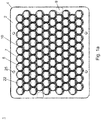
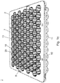
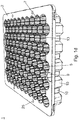
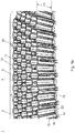
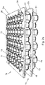
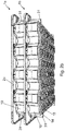
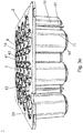
- the Figures 1a to 1d show a holding structure 1 according to a first embodiment of the present invention in different views.
- the holding structure 1 has a plurality of receptacles 5 which are arranged in a regular arrangement (array) and serve to hold pharmaceutical containers therein, in particular vials or carpules.
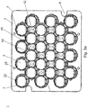
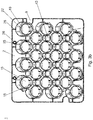
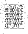
- the receptacles 5 have a polygonal cross section. It is preferred a hexagonal basic shape, as in the embodiment according to FIGS Figures 1a to 1f shown, or an octagonal basic shape, as in the embodiment according to FIGS Figures 3a to 3g shown. In principle, however, a triangular basic shape or a square, rectangular or diamond-shaped basic shape are also conceivable.
- the receptacles 5 Corresponding to the basic shape of the receptacles 5, these are arranged directly adjacent to one another in a regular arrangement. So is in the Fig. 1a a hexagonal, honeycomb arrangement of the recordings 5 can be seen in the Fig. 3a an octagonal arrangement. In principle, however, the receptacles 5 can, for example, be arranged in rows and columns running perpendicular thereto.
- the opening width of the identically designed receptacles 5 is matched to a maximum outside diameter or a maximum outside dimension of the containers to be accommodated therein that they are accommodated only with a comparatively small amount of play. It is preferred here if the containers are accommodated in the receptacles 5 over the greater part of their axial length in order to prevent undesired tilting or wobbling of the containers in the receptacles.
- the game of the container in the receptacles 5 is expediently adjusted via guide ribs, as explained in more detail below.
- the receptacles 5 are formed by side walls 10, which are formed circumferentially, which should not rule out the possibility that, for example, perforations or recesses are formed in sections in the side walls 10 in order to reduce weight or save material.
- the side walls 10 project preferably at right angles from the plate-shaped top 2 of the holding structure 1.
- the side walls can in principle also be inclined radially inward at a comparatively small angle of, for example, a maximum of 1 ° or a maximum of 2 ° relative to a perpendicular to the top 2.
- a common partition is formed between each two directly adjacent receptacles 5, which at the same time serves as a side wall 10 of two mutually adjacent receptacles 5.
- the side walls 10 are formed in one piece and from a solid material, that is to say rectangular in cross section. This is expressly not intended to rule out the fact that slots or recesses are not provided at the lower or upper ends of the side walls 10.
- the side walls used as a common partition wall are at least 80% of their height (H; cf. Fig. 1e or 3d ) formed from a solid material.
- the upper side thereof is designed as a plate-shaped carrier 2, which expediently has rounded corners.
- these openings 25 can be enclosed by frustoconical projections 26, as in FIG Figure 1b shown, which can also serve as spacer elements to adjust the distance between holding structures when they are stacked on top of each other, as below with reference to FIG Figures 2a to 2d described in more detail.
- the upper ends of the side walls 10 facing the upper side 2 of the holding structure 1 can have an arcuate concavely curved course, with a reversal point in the middle between respective corner areas 12 of the receptacles 5 and with vertices at the connecting areas 11 of several side walls 10.
- the edge 3 is at right angles from the top 2 angled (cf. Figure 1c ).
- the aforementioned circumferential, zigzag-shaped edge web on the underside of the holding structure 1 is connected to the angled edge 3 at several positions via connecting webs 28.
- holding projections 22 acting as holding sections are provided, which extend radially inward into the receptacles 5.
- Each receptacle 5 expediently has two holding projections 22 which are diametrically opposite one another.
- the holding projections 22 limit the axial mobility of the containers received in the receptacles 5 by means of a form fit and hold the containers in the receptacles 5, as is shown below with reference to FIG Figures 4b and 4c described in more detail.
- a single holding projection 22 is also sufficient for this purpose, which can also be designed to be circumferential or essentially circumferential.
- the receptacles 5 are axially limited by circumferential end rings 14 which are connected to the lower ends of the side walls 10.
- the aforementioned holding projections 22 are preferably formed on these end rings 14.
- the lower ends of the side walls 10 together form a hexagonal pattern with perforations (the openings 15).
- the lower ends of the side walls 10 together preferably span a plane which extends parallel to the plate-shaped top 2 of the holding structure 1.
- the end rings 14 protrude downward from this plane.
- the end rings 14 form a continuous transition between the polygonal (here hexagonal) basic shape of the receptacles 5 and a circular ring which encloses the openings 15 at the lower ends of the receptacles 5. This offers advantages in the design of tool halves for injection molding of the holding structure 1.
- the side walls 10 are connected to one another in the corner regions 12 over the entire axial length of the receptacles 5.
- the point-symmetrical (here star-shaped) connection areas 11 ensure a uniform flow of force. Overall, these measures increase the inherent rigidity of the holding structure 1.
- guide ribs 18 are provided which protrude radially inward into the receptacles 5 so that the side walls of the containers bear directly on the guide ribs 18 and are guided by them when they are inserted into the receptacles 5.
- the guide ribs 18 extend essentially over the entire length of the receptacles 5 in their longitudinal direction.
- the guide ribs 18 can begin at a little distance from the upper side 2 of the holding structure 1 and each extend down to the lower end of the receptacles 5, more precisely to the transition area to the end rings 14 are inclined relative to the guide ribs 18 at an acute angle. The one in the Fig.
- the guide ribs 18 are designed as flat insertion bevels.
- the upper ends of the lead-in bevels 19 merge into the side walls 10.
- the guide ribs 18 can be symmetrically wider from the upper end to the lower end.
- the guide ribs 18 are arranged in the central region of the side walls 10, it is preferred according to the invention if the guide ribs 18 are arranged in the corner regions 12 of the receptacles 5, as is the case for the third embodiment according to FIGS Figures 3a to 3g is shown.
- the clearance of the containers in the receptacles 5 can be precisely adjusted via the protrusion of the guide ribs from the associated side wall 10 or from the associated corner area 12.
- an outer diameter of the end rings 14 is smaller than a minimum opening width of the receptacles 5 at their upper ends. This enables identically designed holding structures to be stacked on top of one another in a space-saving manner. Such a stacked arrangement of two identically designed holding structures 1a and 1b is illustrated below with reference to FIG Figures 2a to 2d described in more detail.
- the end rings 14 at the lower ends of the receptacles 5 of an upper holding structure 1a slightly dip into the upper ends of the receptacles 5 of the lower holding structure 1b arranged underneath, so that the upper holding structure 1a is not laterally relative to the lower one due to the form fit formed in this way Holding structure 1b can slip.
- the immersion depth or the distance between the holding structures 1a, 1b is set by means of spacer elements 31 which rest on an associated structure on the upper side of a lower holding structure 1b or engage in this. How to get the Fig.
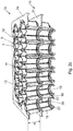
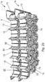
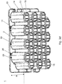
- the Figures 3a to 3g show in various views a holding structure according to a third embodiment of the present invention.
- the receptacles 5 in this embodiment are octagonal.
- two directly adjacent receptacles 5 always share only a single side wall 10.
- a central connecting section 40 with an essentially rectangular basic shape is thus formed.
- this central connecting section 40 can also be formed in one piece from a solid material.
- this central connecting section 40 is designed as a cuboidal cavity 43 which, starting from the top 2 of the holding structure 1, extends over the entire length of the receptacles 5 and whose lower end is open. Through this nevertheless, sufficient inherent rigidity of the holding structure 1 can be achieved. How to do the Figures 3a and 3b can be seen, an opening is formed at the upper end of the cavity 43. In the production of such a holding structure by injection molding from a plastic, this cavity 43 is predetermined by a cuboid projection on one half of the molding tool. A projection at the upper end of this cuboid projection is used for a rigid connection with the opposite half of the molding tool, so that the holding structure 1 can be produced even more precisely.
- the opening 42 formed by this projection can later serve as a vent opening to enable a gas to flow between the bottom and the top of the holding structure 1, for example a gas that is used to sterilize the holding structure 1 and / or the containers held on it such as ethylene oxide (ETO).
- ETO ethylene oxide
- the guide ribs 18 in the third embodiment are always arranged in the corner regions 12 of the receptacles 5.
- the guide ribs 18 can protrude inwardly into the receptacles 5 in a direction (x) towards the geometric center M of the respective receptacle 5, so that the guide ribs 18 are each diametrically opposite.
- the guide ribs protrude inwardly into the receptacles 5 in a direction which deviates from this direction (x) at a small angle (for example in the range between 1 ° and 10 °).
- a holding structure according to the first and second exemplary embodiment with a hexagonal basic shape of the receptacles 5 can be used in particular for containers with a comparatively small nominal volume (for example up to a maximum of 15 ml), with a comparatively small diameter or for tall, relatively slim containers.
- a holding structure according to the third exemplary embodiment with an octagonal basic shape of the receptacles 5 can be used in particular for containers with a comparatively large nominal volume (for example greater than 15 ml), with a comparatively large diameter or for low, relatively wide containers.
- the inherent rigidity of the holding structure 1 also enables the containers to be further processed while they are being received in the receptacles 5. It is conceivable, for example, that a holding structure 1 is placed on a holding frame along the edge of its underside and then closing elements, for example closing plugs, are placed on the ends of the containers and these are axially displaced, preferably at the same time for all containers received in the receptacles of the holding structure or for one or several rows of containers.
- the prevailing forces are sufficiently compensated by the holding structure, so that there is only a slight deflection of the holding structure (for example of a maximum of 2.0 mm over the length of the holding structure), so that tilting of the closure elements can be avoided.
- the axial course of the guide ribs 18 is optimized for better threading and insertion of the containers into the receptacles. Examples of this can be found in the German utility model 20 2016 107 209 and in the undisclosed German Patent application 10 2017 101 398.9 the applicant or in the WO 2017/038878 A1 .
- the guide ribs 18 are conventionally not optimized with regard to their cross section. An unfavorable cross-section of the guide ribs, especially if the container is in a slightly eccentric position, can lead to undesirable abrasion or visible damage, such as scratch marks (so-called vial marks), which the customer will not accept.
- a compromise for the geometry of the guide ribs 18 is preferred according to the invention, namely that at least at the lower ends of the guide ribs 18 (or over the entire length of the guide ribs 18 ) in each case a flattened section 18a is provided, the corner regions 18b of which are rounded, as in FIG Figure 4a shown.
- the Figure 4b shows the receptacle of a carpule 50, which can be inserted vertically from above into the receptacle 5 of a holding structure.
- Carpules 50 are hollow-cylindrical, with a cylindrical side wall 52, which merges into a narrowed neck portion 55 with a smaller outer diameter than the cylindrical side wall 52 via a shoulder portion 54 extending inclined to it, at the front end of which a widened edge 56 with an ejection opening 58 is formed is. This can be closed by a plug (not shown).
- the stopper can be secured at the front end of the carpule 50 by means of a crimped metal cover (so-called pre-crimped cartridge).
- the carpule 50 is designed to be open, with a filling opening 57 through which a liquid substance can be filled.
- the metal lid does not come into contact with the holding projections 22, so that no forces are exerted on it and the plug can reliably close the filling opening 57 of the carpule 50, even if large axial forces act on the carpule 50, for example when inserting the plug into the Filling opening 57 while the carpule 50 is in the position according to FIG Figure 4b is received upside down in the receptacles 5 and supported. In this position, the rear ends of the carpules 50 protrude from the receptacles 5.
- the Figure 4c the reception of a vial 51, which is inserted from vertically above into the receptacle 5 of a holding structure. It is shown that the vial 51 was inserted upright. In principle, however, the vial 51 can also be inserted upside down, in the manner of the carpule, as in FIG Figure 4b shown. In the completely inserted state, the base 53 of the vial 51 is supported on the holding projections 22 and the vial 51 is thus held in the receptacle 5 in an axially secured manner.
- a holding structure 1, as described above, can be used to store and transport pharmaceutical containers, such as vials or carpules, for example.
- the holding structure 1 can be gripped and guided by means of the access openings 9 by grippers or the like.
- the pharmaceutical containers can be further processed or treated while they are held by the holding structure 1, as described above.
- a holding structure can be stored as a so-called nest in a trough-shaped transport or packaging container (so-called tub), for example in the manner shown in FIG EP 2 868 593 A1 the applicant is disclosed, the content of which is hereby included by way of reference for disclosure purposes.
- the transport or packaging container can or can be closed by means of a gas-permeable plastic film be sealed, in particular by means of a plastic film which is formed from a gas-permeable mesh of plastic fibers and is in particular a Tyveck® film.
- a transport or packaging container for sterile transport, such a transport or packaging container, possibly together with other similar transport or packaging containers, can be received in at least one sterile outer packaging bag and packaged in a sterile manner against the environment.
- the at least one sterile outer packaging bag can have a gas-permeable section or even be completely formed by it, which is formed in particular by a mesh made of plastic fibers, such as polypropylene fibers (PP).
- the design of the holding structure is optimized in particular with regard to the achievable packing density.
- the respectively adjacent walls of the receptacles are combined to form a wall that is shared by two adjacent receptacles.
- Thin-walled, easily breakable and difficult to cool rib-like contours in the tool design can thus be avoided according to the invention, which results in a longer service life of the tool.
- the cycle time of the manufacturing process can be shortened significantly and unit costs can be reduced.
- the conventionally round geometry of the receptacles is converted according to the invention into a hexagonal structure for relatively small volumes of the containers (for example up to 15 ml) and for even larger volumes of the containers (for example greater than 15 ml) into an octagonal structure with a 45 ° - and 90 ° arrangement of the recordings is possible.
- a very high packing density can be achieved in this way.
- the design of the tool for production by injection molding from a plastic is significantly simplified. Cooling of the tools and the material is very easy to implement and the cores of the tools can be produced easily and also in a standardized manner.
- the design of the holding structure is also optimized with regard to rigidity and lightweight construction.
- the honeycomb design offers considerable advantages in terms of the deflection requirements (a deflection of max. 2 mm based on the entire surface of the holding surface and measured when empty could be achieved without any problems).
- the angular design of the receptacles in combination with the guide ribs also enables good accessibility for steam sterilization (for example using ETO in an autoclave).
- a horizontal (flat) tool separation also has a very favorable effect on the separation forces when demolding the holding structure and thus on the risk of the formation of disruptive burrs and thus potential particles due to tool wear. In addition, the tool separation no longer takes place in the immediate area of the holding structure itself.
- a holding structure according to the present invention Due to the optimized position of the tool parting plane, a holding structure according to the present invention has proven to be fully suitable for clean rooms, because the risk of the formation of particles when demolding the holding structure but also during later use (in particular due to the optimized geometry of the guide ribs 18) is significant can be reduced.
- a holding structure within the meaning of the present invention can be formed in one piece in particular by injection molding from a plastic. In principle, production by 3D printing from a plastic is also conceivable.
- a further aspect of the present invention which can also be explicitly claimed as an independent invention by means of an independent patent claim, relates to a computer- or processor-readable file, also for transmission over networks, such as an internal company computer network or over the Internet, comprising instructions or information. Control commands that, when loaded by a computer or processor, cause a 3D printer, under the control of the computer or processor, to create a holding structure as disclosed in the present application, made of a suitable material, in particular a plastic material, in three-dimensional shape.
Landscapes
- Engineering & Computer Science (AREA)
- Health & Medical Sciences (AREA)
- Mechanical Engineering (AREA)
- General Health & Medical Sciences (AREA)
- Veterinary Medicine (AREA)
- Public Health (AREA)
- Life Sciences & Earth Sciences (AREA)
- Animal Behavior & Ethology (AREA)
- Pharmacology & Pharmacy (AREA)
- Chemical & Material Sciences (AREA)
- Chemical Kinetics & Catalysis (AREA)
- Clinical Laboratory Science (AREA)
- Ceramic Engineering (AREA)
- Hematology (AREA)
- Containers Having Bodies Formed In One Piece (AREA)
- Packages (AREA)
- Stackable Containers (AREA)
- Medical Preparation Storing Or Oral Administration Devices (AREA)
Applications Claiming Priority (2)
| Application Number | Priority Date | Filing Date | Title |
|---|---|---|---|
| DE102018111491.5A DE102018111491A1 (de) | 2018-05-14 | 2018-05-14 | Haltestruktur zum gleichzeitigen Halten einer Mehrzahl von Behältern für Substanzen für pharmazeutische, medizinische oder kosmetische Anwendungen, Transportgebilde und Transport- oder Verpackungsbehälter mit selbiger |
| EP19170288.5A EP3569314B1 (fr) | 2018-05-14 | 2019-04-18 | Structure de support permettant de supporter simultanément une pluralité de récipients pour substances destinées à des applications médicales, pharmaceutiques ou cosmétiques ainsi que récipient de transport doté de ladite structure |
Related Parent Applications (1)
| Application Number | Title | Priority Date | Filing Date |
|---|---|---|---|
| EP19170288.5A Division EP3569314B1 (fr) | 2018-05-14 | 2019-04-18 | Structure de support permettant de supporter simultanément une pluralité de récipients pour substances destinées à des applications médicales, pharmaceutiques ou cosmétiques ainsi que récipient de transport doté de ladite structure |
Publications (2)
| Publication Number | Publication Date |
|---|---|
| EP3862095A1 true EP3862095A1 (fr) | 2021-08-11 |
| EP3862095B1 EP3862095B1 (fr) | 2022-08-24 |
Family
ID=66239917
Family Applications (2)
| Application Number | Title | Priority Date | Filing Date |
|---|---|---|---|
| EP21158799.3A Active EP3862095B1 (fr) | 2018-05-14 | 2019-04-18 | Structure de support permettant de supporter simultanément une pluralité de récipients pour substances destinées à des applications médicales, pharmaceutiques ou cosmétiques ainsi que récipient de transport en étant doté |
| EP19170288.5A Active EP3569314B1 (fr) | 2018-05-14 | 2019-04-18 | Structure de support permettant de supporter simultanément une pluralité de récipients pour substances destinées à des applications médicales, pharmaceutiques ou cosmétiques ainsi que récipient de transport doté de ladite structure |
Family Applications After (1)
| Application Number | Title | Priority Date | Filing Date |
|---|---|---|---|
| EP19170288.5A Active EP3569314B1 (fr) | 2018-05-14 | 2019-04-18 | Structure de support permettant de supporter simultanément une pluralité de récipients pour substances destinées à des applications médicales, pharmaceutiques ou cosmétiques ainsi que récipient de transport doté de ladite structure |
Country Status (7)
| Country | Link |
|---|---|
| US (2) | US20190343721A1 (fr) |
| EP (2) | EP3862095B1 (fr) |
| JP (1) | JP7424758B2 (fr) |
| KR (1) | KR102789439B1 (fr) |
| CN (2) | CN115384923B (fr) |
| CA (1) | CA3042905A1 (fr) |
| DE (1) | DE102018111491A1 (fr) |
Cited By (1)
| Publication number | Priority date | Publication date | Assignee | Title |
|---|---|---|---|---|
| USD1050892S1 (en) | 2022-05-12 | 2024-11-12 | Prince Sterilization Services, LLC | Container carrier |
Families Citing this family (29)
| Publication number | Priority date | Publication date | Assignee | Title |
|---|---|---|---|---|
| JP6929291B2 (ja) | 2016-01-27 | 2021-09-01 | ウエスト ファーマスーティカル サービシーズ インコーポレイテッド | 六角チムニーを備えた中心オフセット付きのシリンジネスト |
| DE102018111491A1 (de) | 2018-05-14 | 2019-11-14 | Schott Schweiz Ag | Haltestruktur zum gleichzeitigen Halten einer Mehrzahl von Behältern für Substanzen für pharmazeutische, medizinische oder kosmetische Anwendungen, Transportgebilde und Transport- oder Verpackungsbehälter mit selbiger |
| DE102018128817A1 (de) | 2018-11-16 | 2020-05-20 | Schott Schweiz Ag | Haltestruktur zum gleichzeitigen Halten einer Mehrzahl von Behältern für Substanzen für pharmazeutische, medizinische oder kosmetische Anwendungen, Transportgebilde und Transport- oder Verpackungsbehälter mit selbiger |
| IT201900011982A1 (it) * | 2019-07-17 | 2021-01-17 | Nuova Ompi Srl | Struttura per il confezionamento di contenitori primari ad uso farmaceutico |
| CN110834798A (zh) * | 2019-11-15 | 2020-02-25 | 海南医学院 | 一种热带地区丝盖伞科真菌科研标本保藏装置 |
| CN111661479B (zh) * | 2020-06-10 | 2025-06-06 | 中山德尚伟业生物科技有限公司 | 面膜包装容器和面膜包装盒 |
| CN115734791A (zh) * | 2020-06-25 | 2023-03-03 | 赛诺菲 | 工件载架 |
| EP3974337B1 (fr) * | 2020-09-25 | 2024-11-06 | SCHOTT Pharma Schweiz AG | Dispositif de retenue limitant le mouvement de conteneurs d'emballage primaire au niveau d'une première position longitudinale et d'autres positions longitudinales |
| EP3978135A1 (fr) * | 2020-09-30 | 2022-04-06 | SCHOTT Schweiz AG | Dispositif de support comprenant un premier et un second composant |
| US12098018B2 (en) * | 2021-01-15 | 2024-09-24 | Oyster Point Pharma, Inc. | Nesting structures for storage, transport, and assembly of drug dispensers and containers |
| CN117120121A (zh) * | 2021-01-26 | 2023-11-24 | 贝克顿迪金森法国公司 | 用于包装柱塞止挡件的、具有确保一堆的嵌套件可靠对准的集成式堆叠特征的嵌套件 |
| CN116802502A (zh) * | 2021-02-19 | 2023-09-22 | 株式会社日立高新技术 | 容器支架、分析装置、容器支架的制造方法 |
| CA3113451A1 (fr) * | 2021-03-30 | 2022-09-30 | Duoject Medical Systems Inc. | Plateau de retenue des cartouches |
| MX2022005952A (es) | 2021-05-18 | 2023-04-10 | Gerresheimer Glas Gmbh | Transporte de unidades de envase. |
| MX2022005963A (es) | 2021-05-18 | 2023-03-01 | Gerresheimer Glas Gmbh | Contenedor para unidades de envasado. |
| US12319466B2 (en) | 2021-05-18 | 2025-06-03 | Gerresheimer Glas Gmbh | Transporting packaging units |
| US20220371765A1 (en) * | 2021-05-18 | 2022-11-24 | Gerresheimer Glas Gmbh | Transport tray for packaging units |
| DE102021115287A1 (de) | 2021-06-14 | 2022-12-15 | Krones Aktiengesellschaft | Behälterbeförderung in einer Behälterbehandlungsanlage |
| CN118488876A (zh) * | 2021-09-15 | 2024-08-13 | 贝克顿·迪金森公司 | 用于血液采集管的可持续且可回收的纸浆托盘 |
| JP2023074202A (ja) | 2021-11-17 | 2023-05-29 | 株式会社リコー | 収容体、レーザー加工装置、及びレーザー加工方法 |
| IT202200015549A1 (it) | 2022-07-25 | 2024-01-25 | Nuova Ompi S R L Unipersonale | Dispositivo di supporto di una pluralità di contenitori per uso farmaceutico da movimentare in una linea di processazione |
| IT202200015591A1 (it) * | 2022-07-25 | 2024-01-25 | Nuova Ompi S R L Unipersonale | Dispositivo di supporto di una pluralità di contenitori per uso farmaceutico da movimentare in una linea di processazione |
| USD1006253S1 (en) * | 2022-09-29 | 2023-11-28 | Schott Pharma Schweiz Ag | Tray for filling of vials, syringes, and cartridges for fill and finish machines |
| US20250136325A1 (en) * | 2023-10-30 | 2025-05-01 | West Pharmaceutical Services, Inc. | Packaging for containers |
| EP4635628A1 (fr) * | 2024-04-15 | 2025-10-22 | SCHOTT Pharma Schweiz AG | Ensemble pour le positionnement de récipients pharmaceutiques pendant le remplissage desdits récipients |
| EP4635530A1 (fr) * | 2024-04-15 | 2025-10-22 | SCHOTT Pharma Schweiz AG | Logement de cartouche, qui présente des caractéristiques de centrage intégré des cartouches |
| USD1119282S1 (en) * | 2024-04-15 | 2026-03-24 | Schott Pharma Schweiz Ag | Portion of a holding structure for pharmaceutical containers |
| EP4717360A1 (fr) * | 2024-09-26 | 2026-04-01 | SCHOTT Pharma Schweiz AG | Empilement de nids pour récipients pharmaceutiques |
| EP4717623A1 (fr) * | 2024-09-26 | 2026-04-01 | SCHOTT Pharma Schweiz AG | Empilement de nids pour récipients pharmaceutiques |
Citations (13)
| Publication number | Priority date | Publication date | Assignee | Title |
|---|---|---|---|---|
| US20090314675A1 (en) * | 2008-06-18 | 2009-12-24 | Norseman Plastics, Ltd. | Beverage crate with constant-diameter pockets |
| WO2010086128A1 (fr) | 2009-01-27 | 2010-08-05 | Stevanato Group International A.S. | Structure d'emballage de récipients pour usage pharmaceutique |
| WO2012126582A1 (fr) | 2011-03-18 | 2012-09-27 | Schott Schweiz Ag | Plaque support et dispositif de transport et/ou de stockage pour des récipients pharmaceutiques |
| CN103359348A (zh) | 2012-03-28 | 2013-10-23 | 斯泰瓦纳托集团国际A.S. | 改进药用容器封装结构、其处理方法、其处理机及其用途 |
| DE102012103896A1 (de) | 2012-05-03 | 2013-11-07 | Schott Ag | Haltestruktur zum gleichzeitigen Halten einer Mehrzahl von medizinischen oder pharmazeutischen Behältern sowie Transport- oder Verpackungsbehälter mit Selbiger |
| WO2014130349A1 (fr) | 2013-02-21 | 2014-08-28 | Capitol Medical Devices, Inc. | Flacon, plateau et ensemble de traitement de flacon |
| EP2868593A1 (fr) | 2013-11-05 | 2015-05-06 | Schott AG | Structure de support pour le support simultané d'une pluralité de récipients pour des substances pour des applications médicales, pharmaceutiques ou cosmétiques, récipient de transport ou d'emballage doté de celle-ci et procédé |
| US20150166217A1 (en) | 2013-12-18 | 2015-06-18 | Schott Ag | Transport and packaging container for accommodating a plurality of containers for medical, pharmaceutical or cosmetic applications as well as methods and uses thereof |
| EP2886983A1 (fr) * | 2012-07-13 | 2015-06-24 | Schott AG | Structure de support pour le support simultané d'une pluralité de récipients pour des substances pour des applications médicales, pharmaceutiques ou cosmétiques et récipient de transport ou d'emballage doté de celle-ci |
| WO2017038878A1 (fr) | 2015-09-04 | 2017-03-09 | 株式会社大協精工 | Élément porte-récipients et ensemble de récipients médicaux |
| DE202016107209U1 (de) | 2016-12-21 | 2018-03-22 | Schott Schweiz Ag | Haltestruktur zum gleichzeitigen Halten einer Mehrzahl von Behältern für Substanzen für pharmazeutische, medizinische oder kosmetische Anwendungen, Transportgebilde und Transport- oder Verpackungsbehälter mit selbiger |
| DE102017101398A1 (de) | 2017-01-25 | 2018-07-26 | Schott Schweiz Ag | Haltestruktur zum gleichzeitigen Halten einer Mehrzahl von Behältern für Substanzen für pharmazeutische, medizinische oder kosmetische Anwendungen, Transportgebilde und Transport- oder Verpackungsbehälter mit selbiger |
| DE102018111491A1 (de) | 2018-05-14 | 2019-11-14 | Schott Schweiz Ag | Haltestruktur zum gleichzeitigen Halten einer Mehrzahl von Behältern für Substanzen für pharmazeutische, medizinische oder kosmetische Anwendungen, Transportgebilde und Transport- oder Verpackungsbehälter mit selbiger |
Family Cites Families (21)
| Publication number | Priority date | Publication date | Assignee | Title |
|---|---|---|---|---|
| US3342397A (en) * | 1967-01-30 | 1967-09-19 | Duitsman Kenneth | Divided food service tray |
| US4549656A (en) * | 1983-08-09 | 1985-10-29 | Barnes Joey L | Package device and method of manufacturing |
| US5285907A (en) | 1992-05-14 | 1994-02-15 | Becton, Dickinson And Company | Modular tube rack arrays |
| JP3100849B2 (ja) | 1994-11-11 | 2000-10-23 | 株式会社東芝 | 半導体記憶装置 |
| DE19815993C2 (de) | 1998-04-09 | 2003-03-06 | Schott Glas | Behälter zur Gefriertrocknung und Aufbewahrung medizinischer Produkte |
| US6462276B2 (en) * | 2001-01-05 | 2002-10-08 | Yazaki North America | Power distribution box cover with anti-rattle feature |
| JP3100849U (ja) * | 2003-10-03 | 2004-05-27 | 株式会社ニチロ | 冷凍食品用トレイ |
| US7658887B2 (en) | 2004-09-02 | 2010-02-09 | Scientific Specialties, Inc. | Pipette tip grid with lock mechanism |
| WO2010062602A1 (fr) * | 2008-10-28 | 2010-06-03 | West Pharmaceutical Services, Inc. | Cavité de piston de seringue pour la fabrication d’ampoules-seringues |
| IT1399750B1 (it) * | 2010-04-30 | 2013-05-03 | Stevanato Group Internat As | Struttura di imballaggio per contenitori ad uso farmaceutico |
| IN2012DE00925A (fr) | 2012-03-28 | 2015-09-04 | Stevanato Group Internat As | |
| DE102012111624A1 (de) * | 2012-05-03 | 2013-11-07 | Schott Ag | Verfahren zur Behandlung oder Verarbeitung von Behältern für medizinische oder pharmazeutische Anwendungen sowie Träger und Transport- oder Verpackungsbehälter hierfür |
| ITVI20120215A1 (it) | 2012-08-30 | 2014-03-01 | Fedegari Autoclavi | Struttura per il confezionamento di componenti per contenitori ad uso farmaceutico |
| KR101976097B1 (ko) * | 2012-11-12 | 2019-05-09 | 쇼오트 아게 | 의료, 의약 또는 화장품 용도의 물질용 용기를 조작 또는 처리하는 프로세스 및 장치 |
| CN106456883B (zh) * | 2014-03-12 | 2019-11-05 | 魏民 | 自动药物注射装置 |
| CA2977087C (fr) * | 2015-02-23 | 2023-03-21 | Nuova Ompi S.R.L. | Structure d'emballage pour recipients pour usage pharmaceutique |
| AU2015391635B2 (en) * | 2015-04-17 | 2019-05-16 | Schott Kaisha Pvt Ltd | Supporting structure for sealed cartridges, transport or packaging container and process |
| JP6929291B2 (ja) | 2016-01-27 | 2021-09-01 | ウエスト ファーマスーティカル サービシーズ インコーポレイテッド | 六角チムニーを備えた中心オフセット付きのシリンジネスト |
| WO2018020505A1 (fr) * | 2016-07-27 | 2018-02-01 | Schott Kaisha Pvt. Ltd. | Procédé de fermeture de flacons, structure de support pour supporter des éléments de fermeture de flacon et contenant de transport ou d'emballage |
| CN206466359U (zh) * | 2016-09-18 | 2017-09-05 | 苏乃灌 | 层叠式陶瓷器皿的无缝组合结构 |
| US12098018B2 (en) * | 2021-01-15 | 2024-09-24 | Oyster Point Pharma, Inc. | Nesting structures for storage, transport, and assembly of drug dispensers and containers |
-
2018
- 2018-05-14 DE DE102018111491.5A patent/DE102018111491A1/de not_active Withdrawn
-
2019
- 2019-04-18 EP EP21158799.3A patent/EP3862095B1/fr active Active
- 2019-04-18 EP EP19170288.5A patent/EP3569314B1/fr active Active
- 2019-04-26 KR KR1020190049174A patent/KR102789439B1/ko active Active
- 2019-05-05 CN CN202211210491.3A patent/CN115384923B/zh active Active
- 2019-05-05 CN CN201910368017.5A patent/CN110481984B/zh active Active
- 2019-05-10 CA CA3042905A patent/CA3042905A1/fr not_active Abandoned
- 2019-05-13 JP JP2019090696A patent/JP7424758B2/ja active Active
- 2019-05-14 US US16/411,904 patent/US20190343721A1/en not_active Abandoned
-
2024
- 2024-07-01 US US18/760,780 patent/US12465552B2/en active Active
Patent Citations (15)
| Publication number | Priority date | Publication date | Assignee | Title |
|---|---|---|---|---|
| US20090314675A1 (en) * | 2008-06-18 | 2009-12-24 | Norseman Plastics, Ltd. | Beverage crate with constant-diameter pockets |
| WO2010086128A1 (fr) | 2009-01-27 | 2010-08-05 | Stevanato Group International A.S. | Structure d'emballage de récipients pour usage pharmaceutique |
| WO2012126582A1 (fr) | 2011-03-18 | 2012-09-27 | Schott Schweiz Ag | Plaque support et dispositif de transport et/ou de stockage pour des récipients pharmaceutiques |
| CN103359348A (zh) | 2012-03-28 | 2013-10-23 | 斯泰瓦纳托集团国际A.S. | 改进药用容器封装结构、其处理方法、其处理机及其用途 |
| DE102012103896A1 (de) | 2012-05-03 | 2013-11-07 | Schott Ag | Haltestruktur zum gleichzeitigen Halten einer Mehrzahl von medizinischen oder pharmazeutischen Behältern sowie Transport- oder Verpackungsbehälter mit Selbiger |
| EP2886983A1 (fr) * | 2012-07-13 | 2015-06-24 | Schott AG | Structure de support pour le support simultané d'une pluralité de récipients pour des substances pour des applications médicales, pharmaceutiques ou cosmétiques et récipient de transport ou d'emballage doté de celle-ci |
| WO2014130349A1 (fr) | 2013-02-21 | 2014-08-28 | Capitol Medical Devices, Inc. | Flacon, plateau et ensemble de traitement de flacon |
| EP2868593A1 (fr) | 2013-11-05 | 2015-05-06 | Schott AG | Structure de support pour le support simultané d'une pluralité de récipients pour des substances pour des applications médicales, pharmaceutiques ou cosmétiques, récipient de transport ou d'emballage doté de celle-ci et procédé |
| US20150166217A1 (en) | 2013-12-18 | 2015-06-18 | Schott Ag | Transport and packaging container for accommodating a plurality of containers for medical, pharmaceutical or cosmetic applications as well as methods and uses thereof |
| DE102013114404A1 (de) * | 2013-12-18 | 2015-06-18 | Schott Ag | Transport- und Verpackungsbehälter mit einer Haltestruktur zum gleichzeitigen Halten einer Mehrzahl von Behältern für medizinische, pharmazeutische oder kosmetische Anwendungen sowie Verfahren und Verwendungen hiervon |
| WO2017038878A1 (fr) | 2015-09-04 | 2017-03-09 | 株式会社大協精工 | Élément porte-récipients et ensemble de récipients médicaux |
| DE202016107209U1 (de) | 2016-12-21 | 2018-03-22 | Schott Schweiz Ag | Haltestruktur zum gleichzeitigen Halten einer Mehrzahl von Behältern für Substanzen für pharmazeutische, medizinische oder kosmetische Anwendungen, Transportgebilde und Transport- oder Verpackungsbehälter mit selbiger |
| DE102017101398A1 (de) | 2017-01-25 | 2018-07-26 | Schott Schweiz Ag | Haltestruktur zum gleichzeitigen Halten einer Mehrzahl von Behältern für Substanzen für pharmazeutische, medizinische oder kosmetische Anwendungen, Transportgebilde und Transport- oder Verpackungsbehälter mit selbiger |
| EP3354589A1 (fr) | 2017-01-25 | 2018-08-01 | SCHOTT Schweiz AG | Structure de support permettant de supporter simultanément une pluralité de récipients pour substances destinées à des applications médicales, pharmaceutiques ou cosmétiques, élément de transport et récipient de transport ou d'emballage dotés de ladite structure |
| DE102018111491A1 (de) | 2018-05-14 | 2019-11-14 | Schott Schweiz Ag | Haltestruktur zum gleichzeitigen Halten einer Mehrzahl von Behältern für Substanzen für pharmazeutische, medizinische oder kosmetische Anwendungen, Transportgebilde und Transport- oder Verpackungsbehälter mit selbiger |
Cited By (1)
| Publication number | Priority date | Publication date | Assignee | Title |
|---|---|---|---|---|
| USD1050892S1 (en) | 2022-05-12 | 2024-11-12 | Prince Sterilization Services, LLC | Container carrier |
Also Published As
| Publication number | Publication date |
|---|---|
| US20190343721A1 (en) | 2019-11-14 |
| KR102789439B1 (ko) | 2025-03-31 |
| CN110481984B (zh) | 2022-10-21 |
| JP7424758B2 (ja) | 2024-01-30 |
| US12465552B2 (en) | 2025-11-11 |
| EP3569314B1 (fr) | 2021-03-17 |
| JP2019198650A (ja) | 2019-11-21 |
| KR20190130481A (ko) | 2019-11-22 |
| US20240350362A1 (en) | 2024-10-24 |
| CN110481984A (zh) | 2019-11-22 |
| DE102018111491A1 (de) | 2019-11-14 |
| EP3569314A1 (fr) | 2019-11-20 |
| CA3042905A1 (fr) | 2019-11-14 |
| EP3862095B1 (fr) | 2022-08-24 |
| CN115384923A (zh) | 2022-11-25 |
| CN115384923B (zh) | 2023-08-15 |
Similar Documents
| Publication | Publication Date | Title |
|---|---|---|
| EP3569314B1 (fr) | Structure de support permettant de supporter simultanément une pluralité de récipients pour substances destinées à des applications médicales, pharmaceutiques ou cosmétiques ainsi que récipient de transport doté de ladite structure | |
| EP3354589B1 (fr) | Structure de support permettant de supporter simultanément une pluralité de récipients pour substances destinées à des applications médicales, pharmaceutiques ou cosmétiques, élément de transport et récipient de transport ou d'emballage dotés de ladite structure | |
| DE202018106510U1 (de) | Haltestruktur mit einer Mehrzahl von daran gehaltenen Behältern für Substanzen für pharmazeutische, medizinische oder kosmetische Anwendungen sowie Transport- oder Verpackungsbehälter mit selbiger | |
| DE102018128817A1 (de) | Haltestruktur zum gleichzeitigen Halten einer Mehrzahl von Behältern für Substanzen für pharmazeutische, medizinische oder kosmetische Anwendungen, Transportgebilde und Transport- oder Verpackungsbehälter mit selbiger | |
| EP2886983B1 (fr) | Structure de support pour le support simultané d'une pluralité de récipients pour des substances pour des applications médicales, pharmaceutiques ou cosmétiques et récipient de transport ou d'emballage doté de celle-ci | |
| EP2659922B1 (fr) | Structure de support pour le support simultané d'une pluralité de récipients médicaux ou pharmaceutiques ainsi que récipient de transport ou d'emballage doté d'une telle structure | |
| EP2844936B1 (fr) | Procédé et dispositif pour manipuler des récipients et des substances contenues dans ces récipients pour des applications médicales, pharmaceutiques ou cosmétiques | |
| EP3534986A1 (fr) | Structure de retenue servant à retenir simultanément une pluralité de contenants pour substances à usage pharmaceutique, médical ou cosmétique, structure de transport et contenant de transport ou d'emballage la comportant | |
| EP3199187B1 (fr) | Plaque de support pour récipients pharmaceutiques | |
| EP3210669B1 (fr) | Procédé de transfert d'une pluralité de récipients et/ou d'éléments de fermeture dans une salle blanche et récipient de transport et d'emballage | |
| DE102013112167A1 (de) | Haltestruktur zum gleichzeitigen Halten einer Mehrzahl von Behältern für Substanzen für medizinische, pharmazeutische oder kosmetische Anwendungen sowie Transport- und Verpackungsbehälter mit Selbiger sowie Verfahren | |
| DE202015009695U1 (de) | Haltestruktur zum Halten einer Mehrzahl von abgedichteten Karpulen, Transport- oder Verpackungsbehälter mit einer solchen Haltestruktur sowie Haltestruktur mit einer Mehrzahl von abgedichteten Karpulen | |
| EP2896406A2 (fr) | Structure d'emballage et procédé d'emballage stérile de récipients pour des substances d'applications médicales, pharmaceutiques ou cosmétiques et procédé de traitement de récipients utilisant la structure d'emballage | |
| EP3202672B1 (fr) | Unité d'emballage stérile à usage médical | |
| EP3329997A1 (fr) | Structure de maintien permettant de tenir une multitude de flacons, utilisation d'une telle structure ainsi que procédé de traitement de telles flacons | |
| EP0887282A1 (fr) | Récipient prêt a la vente pour le transport des lentilles de contact et lentille de contact pour ce récipient | |
| DE102012110339B4 (de) | Haltestruktur zum gleichzeitigen Halten einer Mehrzahl von medizinischen oder pharmazeutischen Behältern sowie Transport- oder Verpackungsbehälter mit Selbiger und Verfahren zur Behandlung solcher Behälter | |
| EP2867130A1 (fr) | Dispositif pour stocker et/ou transporter une pluralité de contenants d'emballage | |
| DE102012108215A1 (de) | Haltestruktur zum gleichzeitigen Halten einer Mehrzahl von Behältern für Substanzen für medizinische, pharmazeutische oder kosmetische Anwendungen sowie Transport- oder Verpackungsbehälter mit selbiger | |
| EP3202434B1 (fr) | Unité d'emballage de module de filtre | |
| EP0208062A2 (fr) | Réceptacle pour une pluralité d'objets en forme de disque et élément de ce réceptacle | |
| EP2659981A1 (fr) | Structure de support pour le support simultané d'une pluralité de récipients pour des applications médicales, pharmaceutiques ou cosmétiques ainsi que récipient de transport ou d'emballage et procédé de traitement de tels récipients | |
| DE20215803U1 (de) | Träger zur Aufnahme einer Vielzahl von Behältern | |
| DE10159382A1 (de) | Transportbehälter für Werkzeuge und/oder Werkstücke | |
| DE102022125891A1 (de) | Halteeinrichtung für beutel und behälter zur aufnahme von beuteln mit mindestens einer halteeinrichtung |
Legal Events
| Date | Code | Title | Description |
|---|---|---|---|
| PUAI | Public reference made under article 153(3) epc to a published international application that has entered the european phase |
Free format text: ORIGINAL CODE: 0009012 |
|
| STAA | Information on the status of an ep patent application or granted ep patent |
Free format text: STATUS: THE APPLICATION HAS BEEN PUBLISHED |
|
| AC | Divisional application: reference to earlier application |
Ref document number: 3569314 Country of ref document: EP Kind code of ref document: P |
|
| AK | Designated contracting states |
Kind code of ref document: A1 Designated state(s): AL AT BE BG CH CY CZ DE DK EE ES FI FR GB GR HR HU IE IS IT LI LT LU LV MC MK MT NL NO PL PT RO RS SE SI SK SM TR |
|
| STAA | Information on the status of an ep patent application or granted ep patent |
Free format text: STATUS: REQUEST FOR EXAMINATION WAS MADE |
|
| 17P | Request for examination filed |
Effective date: 20220125 |
|
| RBV | Designated contracting states (corrected) |
Designated state(s): AL AT BE BG CH CY CZ DE DK EE ES FI FR GB GR HR HU IE IS IT LI LT LU LV MC MK MT NL NO PL PT RO RS SE SI SK SM TR |
|
| GRAP | Despatch of communication of intention to grant a patent |
Free format text: ORIGINAL CODE: EPIDOSNIGR1 |
|
| STAA | Information on the status of an ep patent application or granted ep patent |
Free format text: STATUS: GRANT OF PATENT IS INTENDED |
|
| INTG | Intention to grant announced |
Effective date: 20220321 |
|
| GRAS | Grant fee paid |
Free format text: ORIGINAL CODE: EPIDOSNIGR3 |
|
| GRAA | (expected) grant |
Free format text: ORIGINAL CODE: 0009210 |
|
| STAA | Information on the status of an ep patent application or granted ep patent |
Free format text: STATUS: THE PATENT HAS BEEN GRANTED |
|
| AC | Divisional application: reference to earlier application |
Ref document number: 3569314 Country of ref document: EP Kind code of ref document: P |
|
| AK | Designated contracting states |
Kind code of ref document: B1 Designated state(s): AL AT BE BG CH CY CZ DE DK EE ES FI FR GB GR HR HU IE IS IT LI LT LU LV MC MK MT NL NO PL PT RO RS SE SI SK SM TR |
|
| REG | Reference to a national code |
Ref country code: CH Ref legal event code: EP |
|
| REG | Reference to a national code |
Ref country code: IE Ref legal event code: FG4D Free format text: LANGUAGE OF EP DOCUMENT: GERMAN |
|
| REG | Reference to a national code |
Ref country code: AT Ref legal event code: REF Ref document number: 1513266 Country of ref document: AT Kind code of ref document: T Effective date: 20220915 Ref country code: DE Ref legal event code: R096 Ref document number: 502019005455 Country of ref document: DE |
|
| REG | Reference to a national code |
Ref country code: LT Ref legal event code: MG9D |
|
| REG | Reference to a national code |
Ref country code: NL Ref legal event code: MP Effective date: 20220824 |
|
| RAP4 | Party data changed (patent owner data changed or rights of a patent transferred) |
Owner name: SCHOTT PHARMA SCHWEIZ AG |
|
| PG25 | Lapsed in a contracting state [announced via postgrant information from national office to epo] |
Ref country code: SE Free format text: LAPSE BECAUSE OF FAILURE TO SUBMIT A TRANSLATION OF THE DESCRIPTION OR TO PAY THE FEE WITHIN THE PRESCRIBED TIME-LIMIT Effective date: 20220824 Ref country code: RS Free format text: LAPSE BECAUSE OF FAILURE TO SUBMIT A TRANSLATION OF THE DESCRIPTION OR TO PAY THE FEE WITHIN THE PRESCRIBED TIME-LIMIT Effective date: 20220824 Ref country code: PT Free format text: LAPSE BECAUSE OF FAILURE TO SUBMIT A TRANSLATION OF THE DESCRIPTION OR TO PAY THE FEE WITHIN THE PRESCRIBED TIME-LIMIT Effective date: 20221226 Ref country code: NO Free format text: LAPSE BECAUSE OF FAILURE TO SUBMIT A TRANSLATION OF THE DESCRIPTION OR TO PAY THE FEE WITHIN THE PRESCRIBED TIME-LIMIT Effective date: 20221124 Ref country code: NL Free format text: LAPSE BECAUSE OF FAILURE TO SUBMIT A TRANSLATION OF THE DESCRIPTION OR TO PAY THE FEE WITHIN THE PRESCRIBED TIME-LIMIT Effective date: 20220824 Ref country code: LV Free format text: LAPSE BECAUSE OF FAILURE TO SUBMIT A TRANSLATION OF THE DESCRIPTION OR TO PAY THE FEE WITHIN THE PRESCRIBED TIME-LIMIT Effective date: 20220824 Ref country code: LT Free format text: LAPSE BECAUSE OF FAILURE TO SUBMIT A TRANSLATION OF THE DESCRIPTION OR TO PAY THE FEE WITHIN THE PRESCRIBED TIME-LIMIT Effective date: 20220824 Ref country code: FI Free format text: LAPSE BECAUSE OF FAILURE TO SUBMIT A TRANSLATION OF THE DESCRIPTION OR TO PAY THE FEE WITHIN THE PRESCRIBED TIME-LIMIT Effective date: 20220824 |
|
| PG25 | Lapsed in a contracting state [announced via postgrant information from national office to epo] |
Ref country code: PL Free format text: LAPSE BECAUSE OF FAILURE TO SUBMIT A TRANSLATION OF THE DESCRIPTION OR TO PAY THE FEE WITHIN THE PRESCRIBED TIME-LIMIT Effective date: 20220824 Ref country code: IS Free format text: LAPSE BECAUSE OF FAILURE TO SUBMIT A TRANSLATION OF THE DESCRIPTION OR TO PAY THE FEE WITHIN THE PRESCRIBED TIME-LIMIT Effective date: 20221224 Ref country code: HR Free format text: LAPSE BECAUSE OF FAILURE TO SUBMIT A TRANSLATION OF THE DESCRIPTION OR TO PAY THE FEE WITHIN THE PRESCRIBED TIME-LIMIT Effective date: 20220824 Ref country code: GR Free format text: LAPSE BECAUSE OF FAILURE TO SUBMIT A TRANSLATION OF THE DESCRIPTION OR TO PAY THE FEE WITHIN THE PRESCRIBED TIME-LIMIT Effective date: 20221125 |
|
| REG | Reference to a national code |
Ref country code: DE Ref legal event code: R081 Ref document number: 502019005455 Country of ref document: DE Owner name: SCHOTT PHARMA SCHWEIZ AG, CH Free format text: FORMER OWNER: SCHOTT SCHWEIZ AG, ST. GALLEN, CH |
|
| PG25 | Lapsed in a contracting state [announced via postgrant information from national office to epo] |
Ref country code: SM Free format text: LAPSE BECAUSE OF FAILURE TO SUBMIT A TRANSLATION OF THE DESCRIPTION OR TO PAY THE FEE WITHIN THE PRESCRIBED TIME-LIMIT Effective date: 20220824 Ref country code: RO Free format text: LAPSE BECAUSE OF FAILURE TO SUBMIT A TRANSLATION OF THE DESCRIPTION OR TO PAY THE FEE WITHIN THE PRESCRIBED TIME-LIMIT Effective date: 20220824 Ref country code: ES Free format text: LAPSE BECAUSE OF FAILURE TO SUBMIT A TRANSLATION OF THE DESCRIPTION OR TO PAY THE FEE WITHIN THE PRESCRIBED TIME-LIMIT Effective date: 20220824 Ref country code: DK Free format text: LAPSE BECAUSE OF FAILURE TO SUBMIT A TRANSLATION OF THE DESCRIPTION OR TO PAY THE FEE WITHIN THE PRESCRIBED TIME-LIMIT Effective date: 20220824 Ref country code: CZ Free format text: LAPSE BECAUSE OF FAILURE TO SUBMIT A TRANSLATION OF THE DESCRIPTION OR TO PAY THE FEE WITHIN THE PRESCRIBED TIME-LIMIT Effective date: 20220824 |
|
| REG | Reference to a national code |
Ref country code: DE Ref legal event code: R097 Ref document number: 502019005455 Country of ref document: DE |
|
| PG25 | Lapsed in a contracting state [announced via postgrant information from national office to epo] |
Ref country code: SK Free format text: LAPSE BECAUSE OF FAILURE TO SUBMIT A TRANSLATION OF THE DESCRIPTION OR TO PAY THE FEE WITHIN THE PRESCRIBED TIME-LIMIT Effective date: 20220824 Ref country code: EE Free format text: LAPSE BECAUSE OF FAILURE TO SUBMIT A TRANSLATION OF THE DESCRIPTION OR TO PAY THE FEE WITHIN THE PRESCRIBED TIME-LIMIT Effective date: 20220824 |
|
| P01 | Opt-out of the competence of the unified patent court (upc) registered |
Effective date: 20230512 |
|
| PG25 | Lapsed in a contracting state [announced via postgrant information from national office to epo] |
Ref country code: AL Free format text: LAPSE BECAUSE OF FAILURE TO SUBMIT A TRANSLATION OF THE DESCRIPTION OR TO PAY THE FEE WITHIN THE PRESCRIBED TIME-LIMIT Effective date: 20220824 |
|
| PLBE | No opposition filed within time limit |
Free format text: ORIGINAL CODE: 0009261 |
|
| STAA | Information on the status of an ep patent application or granted ep patent |
Free format text: STATUS: NO OPPOSITION FILED WITHIN TIME LIMIT |
|
| 26N | No opposition filed |
Effective date: 20230525 |
|
| PG25 | Lapsed in a contracting state [announced via postgrant information from national office to epo] |
Ref country code: SI Free format text: LAPSE BECAUSE OF FAILURE TO SUBMIT A TRANSLATION OF THE DESCRIPTION OR TO PAY THE FEE WITHIN THE PRESCRIBED TIME-LIMIT Effective date: 20220824 |
|
| PG25 | Lapsed in a contracting state [announced via postgrant information from national office to epo] |
Ref country code: LU Free format text: LAPSE BECAUSE OF NON-PAYMENT OF DUE FEES Effective date: 20230418 |
|
| REG | Reference to a national code |
Ref country code: BE Ref legal event code: MM Effective date: 20230430 |
|
| PG25 | Lapsed in a contracting state [announced via postgrant information from national office to epo] |
Ref country code: MC Free format text: LAPSE BECAUSE OF FAILURE TO SUBMIT A TRANSLATION OF THE DESCRIPTION OR TO PAY THE FEE WITHIN THE PRESCRIBED TIME-LIMIT Effective date: 20220824 |
|
| PG25 | Lapsed in a contracting state [announced via postgrant information from national office to epo] |
Ref country code: MC Free format text: LAPSE BECAUSE OF FAILURE TO SUBMIT A TRANSLATION OF THE DESCRIPTION OR TO PAY THE FEE WITHIN THE PRESCRIBED TIME-LIMIT Effective date: 20220824 |
|
| REG | Reference to a national code |
Ref country code: IE Ref legal event code: MM4A |
|
| PG25 | Lapsed in a contracting state [announced via postgrant information from national office to epo] |
Ref country code: BE Free format text: LAPSE BECAUSE OF NON-PAYMENT OF DUE FEES Effective date: 20230430 |
|
| PG25 | Lapsed in a contracting state [announced via postgrant information from national office to epo] |
Ref country code: IE Free format text: LAPSE BECAUSE OF NON-PAYMENT OF DUE FEES Effective date: 20230418 |
|
| PG25 | Lapsed in a contracting state [announced via postgrant information from national office to epo] |
Ref country code: IE Free format text: LAPSE BECAUSE OF NON-PAYMENT OF DUE FEES Effective date: 20230418 |
|
| PG25 | Lapsed in a contracting state [announced via postgrant information from national office to epo] |
Ref country code: BG Free format text: LAPSE BECAUSE OF FAILURE TO SUBMIT A TRANSLATION OF THE DESCRIPTION OR TO PAY THE FEE WITHIN THE PRESCRIBED TIME-LIMIT Effective date: 20220824 |
|
| PG25 | Lapsed in a contracting state [announced via postgrant information from national office to epo] |
Ref country code: BG Free format text: LAPSE BECAUSE OF FAILURE TO SUBMIT A TRANSLATION OF THE DESCRIPTION OR TO PAY THE FEE WITHIN THE PRESCRIBED TIME-LIMIT Effective date: 20220824 |
|
| REG | Reference to a national code |
Ref country code: AT Ref legal event code: MM01 Ref document number: 1513266 Country of ref document: AT Kind code of ref document: T Effective date: 20240418 |
|
| PGFP | Annual fee paid to national office [announced via postgrant information from national office to epo] |
Ref country code: DE Payment date: 20250422 Year of fee payment: 7 |
|
| PGFP | Annual fee paid to national office [announced via postgrant information from national office to epo] |
Ref country code: GB Payment date: 20250423 Year of fee payment: 7 |
|
| PGFP | Annual fee paid to national office [announced via postgrant information from national office to epo] |
Ref country code: IT Payment date: 20250424 Year of fee payment: 7 |
|
| PGFP | Annual fee paid to national office [announced via postgrant information from national office to epo] |
Ref country code: FR Payment date: 20250425 Year of fee payment: 7 |
|
| PGFP | Annual fee paid to national office [announced via postgrant information from national office to epo] |
Ref country code: CH Payment date: 20250501 Year of fee payment: 7 |
|
| PG25 | Lapsed in a contracting state [announced via postgrant information from national office to epo] |
Ref country code: AT Free format text: LAPSE BECAUSE OF NON-PAYMENT OF DUE FEES Effective date: 20240418 |
|
| PG25 | Lapsed in a contracting state [announced via postgrant information from national office to epo] |
Ref country code: CY Free format text: LAPSE BECAUSE OF FAILURE TO SUBMIT A TRANSLATION OF THE DESCRIPTION OR TO PAY THE FEE WITHIN THE PRESCRIBED TIME-LIMIT; INVALID AB INITIO Effective date: 20190418 |
|
| PG25 | Lapsed in a contracting state [announced via postgrant information from national office to epo] |
Ref country code: HU Free format text: LAPSE BECAUSE OF FAILURE TO SUBMIT A TRANSLATION OF THE DESCRIPTION OR TO PAY THE FEE WITHIN THE PRESCRIBED TIME-LIMIT; INVALID AB INITIO Effective date: 20190418 |
|
| PG25 | Lapsed in a contracting state [announced via postgrant information from national office to epo] |
Ref country code: TR Free format text: LAPSE BECAUSE OF FAILURE TO SUBMIT A TRANSLATION OF THE DESCRIPTION OR TO PAY THE FEE WITHIN THE PRESCRIBED TIME-LIMIT Effective date: 20220824 |
|
| PGFP | Annual fee paid to national office [announced via postgrant information from national office to epo] |
Ref country code: AT Payment date: 20260410 Year of fee payment: 5 |