EP3862103A1 - Nettoyeur haute pression - Google Patents
Nettoyeur haute pression Download PDFInfo
- Publication number
- EP3862103A1 EP3862103A1 EP21152100.0A EP21152100A EP3862103A1 EP 3862103 A1 EP3862103 A1 EP 3862103A1 EP 21152100 A EP21152100 A EP 21152100A EP 3862103 A1 EP3862103 A1 EP 3862103A1
- Authority
- EP
- European Patent Office
- Prior art keywords
- selection device
- motor
- manual selection
- electric motor
- turned
- Prior art date
- Legal status (The legal status is an assumption and is not a legal conclusion. Google has not performed a legal analysis and makes no representation as to the accuracy of the status listed.)
- Granted
Links
Images


Classifications
-
- B—PERFORMING OPERATIONS; TRANSPORTING
- B08—CLEANING
- B08B—CLEANING IN GENERAL; PREVENTION OF FOULING IN GENERAL
- B08B3/00—Cleaning by methods involving the use or presence of liquid or steam
- B08B3/02—Cleaning by the force of jets or sprays
- B08B3/026—Cleaning by making use of hand-held spray guns; Fluid preparations therefor
- B08B3/028—Spray guns
-
- B—PERFORMING OPERATIONS; TRANSPORTING
- B08—CLEANING
- B08B—CLEANING IN GENERAL; PREVENTION OF FOULING IN GENERAL
- B08B9/00—Cleaning hollow articles by methods or apparatus specially adapted thereto
- B08B9/02—Cleaning pipes or tubes or systems of pipes or tubes
- B08B9/027—Cleaning the internal surfaces; Removal of blockages
- B08B9/032—Cleaning the internal surfaces; Removal of blockages by the mechanical action of a moving fluid, e.g. by flushing
- B08B9/0321—Cleaning the internal surfaces; Removal of blockages by the mechanical action of a moving fluid, e.g. by flushing using pressurised, pulsating or purging fluid
-
- B—PERFORMING OPERATIONS; TRANSPORTING
- B05—SPRAYING OR ATOMISING IN GENERAL; APPLYING FLUENT MATERIALS TO SURFACES, IN GENERAL
- B05B—SPRAYING APPARATUS; ATOMISING APPARATUS; NOZZLES
- B05B12/00—Arrangements for controlling delivery; Arrangements for controlling the spray area
-
- B—PERFORMING OPERATIONS; TRANSPORTING
- B05—SPRAYING OR ATOMISING IN GENERAL; APPLYING FLUENT MATERIALS TO SURFACES, IN GENERAL
- B05B—SPRAYING APPARATUS; ATOMISING APPARATUS; NOZZLES
- B05B9/00—Spraying apparatus for discharge of liquids or other fluent material, without essentially mixing with gas or vapour
- B05B9/03—Spraying apparatus for discharge of liquids or other fluent material, without essentially mixing with gas or vapour characterised by means for supplying liquid or other fluent material
- B05B9/04—Spraying apparatus for discharge of liquids or other fluent material, without essentially mixing with gas or vapour characterised by means for supplying liquid or other fluent material with pressurised or compressible container; with pump
- B05B9/0403—Spraying apparatus for discharge of liquids or other fluent material, without essentially mixing with gas or vapour characterised by means for supplying liquid or other fluent material with pressurised or compressible container; with pump with pumps for liquids or other fluent material
- B05B9/0406—Spraying apparatus for discharge of liquids or other fluent material, without essentially mixing with gas or vapour characterised by means for supplying liquid or other fluent material with pressurised or compressible container; with pump with pumps for liquids or other fluent material with several pumps
-
- B—PERFORMING OPERATIONS; TRANSPORTING
- B08—CLEANING
- B08B—CLEANING IN GENERAL; PREVENTION OF FOULING IN GENERAL
- B08B13/00—Accessories or details of general applicability for machines or apparatus for cleaning
-
- B—PERFORMING OPERATIONS; TRANSPORTING
- B08—CLEANING
- B08B—CLEANING IN GENERAL; PREVENTION OF FOULING IN GENERAL
- B08B9/00—Cleaning hollow articles by methods or apparatus specially adapted thereto
- B08B9/02—Cleaning pipes or tubes or systems of pipes or tubes
- B08B9/027—Cleaning the internal surfaces; Removal of blockages
- B08B9/032—Cleaning the internal surfaces; Removal of blockages by the mechanical action of a moving fluid, e.g. by flushing
- B08B9/0321—Cleaning the internal surfaces; Removal of blockages by the mechanical action of a moving fluid, e.g. by flushing using pressurised, pulsating or purging fluid
- B08B9/0325—Control mechanisms therefor
-
- F—MECHANICAL ENGINEERING; LIGHTING; HEATING; WEAPONS; BLASTING
- F04—POSITIVE - DISPLACEMENT MACHINES FOR LIQUIDS; PUMPS FOR LIQUIDS OR ELASTIC FLUIDS
- F04B—POSITIVE-DISPLACEMENT MACHINES FOR LIQUIDS; PUMPS
- F04B23/00—Pumping installations or systems
- F04B23/04—Combinations of two or more pumps
-
- F—MECHANICAL ENGINEERING; LIGHTING; HEATING; WEAPONS; BLASTING
- F04—POSITIVE - DISPLACEMENT MACHINES FOR LIQUIDS; PUMPS FOR LIQUIDS OR ELASTIC FLUIDS
- F04B—POSITIVE-DISPLACEMENT MACHINES FOR LIQUIDS; PUMPS
- F04B49/00—Control, e.g. of pump delivery, or pump pressure of, or safety measures for, machines, pumps, or pumping installations, not otherwise provided for, or of interest apart from, groups F04B1/00 - F04B47/00
- F04B49/02—Stopping, starting, unloading or idling control
-
- F—MECHANICAL ENGINEERING; LIGHTING; HEATING; WEAPONS; BLASTING
- F04—POSITIVE - DISPLACEMENT MACHINES FOR LIQUIDS; PUMPS FOR LIQUIDS OR ELASTIC FLUIDS
- F04B—POSITIVE-DISPLACEMENT MACHINES FOR LIQUIDS; PUMPS
- F04B49/00—Control, e.g. of pump delivery, or pump pressure of, or safety measures for, machines, pumps, or pumping installations, not otherwise provided for, or of interest apart from, groups F04B1/00 - F04B47/00
- F04B49/06—Control using electricity
-
- G—PHYSICS
- G05—CONTROLLING; REGULATING
- G05D—SYSTEMS FOR CONTROLLING OR REGULATING NON-ELECTRIC VARIABLES
- G05D16/00—Control of fluid pressure
- G05D16/20—Control of fluid pressure characterised by the use of electric means
-
- B—PERFORMING OPERATIONS; TRANSPORTING
- B05—SPRAYING OR ATOMISING IN GENERAL; APPLYING FLUENT MATERIALS TO SURFACES, IN GENERAL
- B05B—SPRAYING APPARATUS; ATOMISING APPARATUS; NOZZLES
- B05B12/00—Arrangements for controlling delivery; Arrangements for controlling the spray area
- B05B12/002—Manually-actuated controlling means, e.g. push buttons, levers or triggers
-
- B—PERFORMING OPERATIONS; TRANSPORTING
- B08—CLEANING
- B08B—CLEANING IN GENERAL; PREVENTION OF FOULING IN GENERAL
- B08B2203/00—Details of cleaning machines or methods involving the use or presence of liquid or steam
- B08B2203/02—Details of machines or methods for cleaning by the force of jets or sprays
- B08B2203/0223—Electric motor pumps
-
- B—PERFORMING OPERATIONS; TRANSPORTING
- B08—CLEANING
- B08B—CLEANING IN GENERAL; PREVENTION OF FOULING IN GENERAL
- B08B2203/00—Details of cleaning machines or methods involving the use or presence of liquid or steam
- B08B2203/02—Details of machines or methods for cleaning by the force of jets or sprays
- B08B2203/027—Pump details
-
- F—MECHANICAL ENGINEERING; LIGHTING; HEATING; WEAPONS; BLASTING
- F04—POSITIVE - DISPLACEMENT MACHINES FOR LIQUIDS; PUMPS FOR LIQUIDS OR ELASTIC FLUIDS
- F04B—POSITIVE-DISPLACEMENT MACHINES FOR LIQUIDS; PUMPS
- F04B2205/00—Fluid parameters
- F04B2205/05—Pressure after the pump outlet
Definitions
- the present invention relates to a pressure washer, that is a high-pressure washing device, for cleaning surfaces by generating a jet of liquid under pressure.
- high pressure washing devices or pressure washers
- a high pressure pump suitable for drawing a washing fluid, for example water
- the dispensing gun generally comprises an elongated body equipped with a handle to which a dispensing wand supporting a dispensing nozzle at the free end thereof can be removably associated.
- the dispensing gun then comprises a trigger which is placed at the handle and actuates a tap adapted to allow or interrupt the flow of the washing fluid from the pump to the dispensing nozzle.
- the fluid sent to the gun is placed under pressure by a motor pump, that is a pump to which an electric motor is mechanically connected with the aim of supplying the pump with the mechanical energy to pressurise the fluid.
- a known type of pressure washers comprises two motor pumps, connected in parallel to one another to an inlet duct of the liquid to be pressurised and to the delivery duct, and a manual selection device, for example fixed to a casing containing the two motor pumps, adapted to selectively allow the actuation of one or both of the motor pumps.
- This configuration allows to increase the pressure and/or the flow rate of pressurised liquid that passes through the delivery duct with a simple control electronics, with a few components and therefore particularly robust as the number of components and the complexity thereof are smaller, consequently the possibility of malfunctions is lower.
- the object of the present invention is to improve the versatility and speed of use of said pressure washers, all within the framework of a simple, rational and robust construction solution.
- the invention particularly, makes available a pressure washer comprising:
- a pressure washer is made available that allows the switching between different levels of pressure/flow rate, without having to interrupt the work as the switching can be carried out comfortably while holding the dispensing gun and which is at the same time particularly robust as it requires a reduced number of control components, therefore the possibility of malfunctions is reduced.
- An aspect of the invention provides that the electronic control apparatus is configured, when the first manual selection device is in the other position between the second position and the third position, to keep the first electric motor and the second electric motor in the operating condition between turned on and off, determined by the first manual selection device irrespective of whether the receiver device intercepts the predetermined wireless signal indicative of the presence of the second manual selection device in the second position.
- the pressure washer thus configured prevents unwanted pressure variations due to accidental switching of the second selection device with respect to what the operator initially decided by setting the first manual selection device in a condition that he does not want to vary.
- the electronic control apparatus can comprise an electronic control unit operatively connected to the receiver device, and a switch operatively connected to the electronic control unit and able to be actuated by said electronic control unit upon receiving the signal from the second manual selection device between a first position, in which the switch is closed and allows the second motor to be turned on, and a second position, in which the switch is open and prevents the second motor from being turned on.
- the pressure washer is particularly robust and reliable as the control of the supply of the motors is carried out by means of a few and not complex components and also because when the complexity of a system increases, the possibility that it can be subject to malfunctions increases.
- the switch comprises a first electrical connector, a second electrical connector and an electrically conductive connection element able to be actuated between a first position, in which it allows the passage of an electric current between the first electrical connector and the second electrical connector, and a second position, in which it prevents the passage of an electric current between the first electrical connector and the second electrical connector.
- the pressure washer can comprise an electric power supply line for the first motor equipped with a first electric power supply cable and a second power supply cable that electrically connect the first selection device to the first motor, and an electric power supply line of the second motor equipped with a first electric power supply cable and a second electric power supply cable that electrically connects the first selection device to the second motor and are independent from one another, and in which the switch of the electronic control apparatus has the first electrical connector electrically connected to the second power supply cable of the second motor and the second electrical connector electrically connected to the second power supply cable of the first motor.
- This aspect contributes to improving the robustness of the pressure washer for the same reasons explained above.
- the electronic control apparatus is configured to selectively turn on or turn off the second motor when the receiver device intercepts the wireless signal indicative of the presence of the second manual selection device in the second position, only when the first manual selection device is in the second position.
- another aspect of the invention provides that the electronic control apparatus can be configured, only when the first selection device is in the third position, to keep both of the motors turned on when the receiver device intercepts the wireless signal indicative of the switching of the second manual selection device from the first position to the second position.
- the pressure washer thus configured prevents unwanted pressure drops due to accidental switching of the second selection device when the user has decided at the start that he wants the maximum pressure/flow rate available.
- the electronic control unit is configured to selectively turn on and turn off the second motor when the receiver device intercepts the wireless signal indicative of the presence of the second manual selection device in the second position, only when the first manual selection device is in the third position.
- another aspect of the invention provides that the electronic control apparatus can be configured, only when the first selection device is in the second position, to keep the first motor turned on and the second motor turned off when the receiver device intercepts the wireless signal indicative of the switching of the second manual selection device from the first position to the second position.
- the pressure washer thus configured prevents unwanted pressure increases due to accidental switching of the second selection device when the user has decided at the start not to want or need the maximum pressure/flow rate available.
- the transmitter device can be configured to emit the wireless signal for a predetermined time period, for example only for a predetermined time period.
- the second manual selection device can be configured to automatically switch from the second position to the first position when it is not actuated.
- the pressure washer is particularly usable and intuitive, since the gesture for carrying out the switching is always the same, so the user does not have to remember directions of actuation corresponding to corresponding operating conditions.
- the pressure washer can comprise a single power supply control apparatus of the first electric motor and of the second electric motor, configured to electrically power supply the first electric motor and the second electric motor so that they rotate, when fully operational, at a single preset rotation speed.
- the pressure washer is particularly robust and resistant, as it is devoid of complex and/or delicate electronic components (for example, such as those required in the case of PWM modulation, pulse modulation width), but at the same time it is versatile in use providing a convenient variation of the dispensed flow rate/pressure.
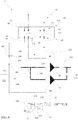
- the reference numeral 1 generally indicates a pressure washer, or a high pressure washing device.
- the pressure washer 1,1' comprises a box-like casing 10, for example made of plastic material, to which a handle and/or wheels (not illustrated) are preferably associated for moving the pressure washer.
- the pressure washer comprises an inlet duct 15 of the fluid to be pressurised, for example a single inlet duct 15 of the fluid to be pressurised, adapted to be connected to a source of fluid to be pressurised, for example a tank or a water network.
- This inlet duct is at least partially contained inside the casing 10.
- the pressure washer 1,1' also comprises a delivery duct 20 of the pressurised fluid, for example a single delivery duct 20 of the pressurised fluid, and a dispensing gun 25 to which said delivery duct is fluidically connected, for example by means of a flexible tubing.
- the delivery duct 20 is for example at least partially contained in the casing 10.
- the dispensing gun 25 comprises a body equipped with a handle to which, for example, a dispensing wand 30 is associated in a removable way, which is equipped at one free end thereof with a dispensing nozzle. Any other cleaning tool can be associated to the dispensing gun, as an alternative to the wand, such as a rotating brush.
- the dispensing gun 25 can comprise a trigger 35 movable between a first position, in which the dispensing gun does not dispense pressurised fluid, for example through the wand and a second position, in which the dispensing gun dispenses the pressurised fluid, for example through the wand.
- the trigger 35 is placed at the handle and actuates a tap between a first position, in which it allows the flow of the pressurised fluid from the delivery duct 20 to the dispensing nozzle, and a second position, in which it interrupts the flow of the pressurised fluid from the delivery duct 20 to the dispensing nozzle.
- the pressure washer comprises a first pump 40, connected at the inlet to the inlet duct 15 and at the outlet to the delivery duct 20, preferably with a fixed displacement.
- the pressure washer 1,1' comprises a first electric motor 45 configured to actuate the first pump 40. That is, the first electric motor 45 is mechanically connected to the first pump 40 to actuate it so as to pressurise the fluid coming from the inlet duct. Overall, the first electric motor 45 and the first pump 40 form a first motor pump of the pressure washer.
- the first electric motor can be, for example only, turned on or turned off, and when it is turned on it actuates the first pump at a preset actuation speed for it to pressurise the fluid.
- the first electric motor 45 is adapted to be electrically connected to an electric energy source 50.
- This electric energy source 50 comprises a pole with greater electric potential and a pole with lower electric potential. If the first motor is three-phase, the electric energy source 50 must also comprise a neutral electric pole.
- the electric energy source 50 can be an electrical connection cable adapted to be connected to the electrical distribution network and/or a battery, for example housed inside the casing 10.
- the first electric motor 45 can be actuated between a first condition, in which it is turned on, i.e. in which it is electrically powered by the electric energy source 50, or in other words still in which it is electrically connected both to the pole with greater electric potential and to the pole with lower electric potential of the electric energy source, and a second condition, in which it is turned off, i.e. in which it is not electrically powered by the electric energy source 50, or in other words still in which it is not electrically connected both to the greater potential pole and to the lower potential pole and no electric current flows in the first motor.
- a first condition in which it is turned on, i.e. in which it is electrically powered by the electric energy source 50, or in other words still in which it is electrically connected both to the pole with greater electric potential and to the pole with lower electric potential of the electric energy source
- a second condition in which it is turned off, i.e. in which it is not electrically powered by the electric energy source 50, or in other words still in which it is not electrically
- the pressure washer 1,1' comprises a second pump 55, connected at the inlet to the inlet duct 15 and at the outlet to the delivery duct 20 in parallel with respect to the first pump 40.
- the inlet duct 15 branches into a first duct connected to the first pump 40 and a second duct connected to the second pump
- the delivery duct comprises a first duct connected to the first pump 40 and a second duct connected to the second pump which, downstream of said pumps with respect to the direction of flow of the pressurised fluid, join into a single duct which is in communication with the dispensing gun.
- the second pump 55 is preferably with fixed displacement.
- the pressure washer 1,1' comprises a second electric motor 60 configured to actuate the second pump 55. That is, the second electric motor 60 is mechanically connected to the second pump 55 to actuate it so as to pressurise the fluid coming from the inlet duct. Overall, the second electric motor 60 and the second pump 55 form a second motor pump of the pressure washer.
- the second electric motor 60 is mechanically independent from the first electric motor and is preferably the same as it.
- the second electric motor 60 can be, for example only, turned on or turned off, and when it is turned on it actuates the second pump for it to pressurise the fluid.
- the second electric motor 60 is adapted to be electrically connected to the electric energy source 50.
- the second electric motor 60 can be actuated between a first condition, in which it is turned on, i.e. in which it is electrically powered by the electric energy source 50, or in other words still in which it is electrically connected both to the pole with greater electric potential and to the pole with lower electric potential of the electric energy source, and a second condition, in which it is turned off, i.e. in which it is not electrically powered by the electric energy source 50, or in other words still in which it is not electrically connected both to the greater potential pole and to the lower potential pole and no electric current flows in the first motor.
- the pressure washer 1,1' is configured so that the first electric motor and the second electric motor rotate, when fully operational, at a single preset rotation speed.
- the pressure washer 1,1' does not comprise devices for controlling the electric motors in PWM (pulse width modulation).
- the pressure washer 1,1' comprises a first manual-type selection device that can be actuated in three positions: a first position, in which the first electric motor 45 and the second electric motor 60 are both turned off, i.e. they are each in the respective second condition, a second position in which only the first electric motor 45 is turned on, i.e. it is in its respective first condition, and the second electric motor 60 is turned off, i.e. it is in its respective second condition, and a third position in in which the first electric motor 45 and the second electric motor 60 are both turned on, i.e. they are both in the respective first condition.
- the first selection device can only be actuated in said three positions.
- “manual type” means that it can be activated manually, preferably it can only be activated manually by an operator.
- the first electric motor 45 and the second electric motor 60 are electrically connected to the electric energy source 50 by interposition of the first selection device.
- the first selection device is connected, for example hooked, to the casing 10, in particular in such a way as to be accessible externally to the casing.
- the first selection device is the only manual control device of the electric motors of the pressure washer associated with the casing 10.
- the first selection device comprises, that is consists of, a switch 65 configured to be stably positioned in the three positions described above.
- Said switch 65 comprises a selection body which can be contacted directly by the user, for example a knob, for selecting the positions.
- Said knob is rotatably associated with a portion of the casing 10 and protrudes externally therefrom (with respect to a compartment in which the motors and the pumps are housed).
- the switch can comprise a plurality of inlet contacts, of which a first electrical contact 70, a second electrical contact 75 and a third electrical contact 80.
- the first electrical contact 70 is connected to the pole with lower electric potential of the electric energy source, the second electrical contact 75 and the third electrical contact 80 are connected, in parallel one another to the pole with greater electric potential of the electric energy source 50 (and are therefore independent from the first electrical contact).
- the switch then comprises a plurality of outlet contacts, of which a first electrical contact 85, a second electrical contact 90 and a third electrical contact 95, independent from one another.
- the switch also comprises an electric selector 100, for example moved by the selection body, which is configured so that when the first selection device is in the first position, the inlet contacts are all electrically isolated from the outlet contacts.
- the electrical selector 100 comprises a first electrical connector 105 shaped and positioned to electrically connect the first electrical contact 70 of the plurality of inlet contacts only with the first electrical contact 85 of the plurality of outlet contacts only when the first selection device is in the second position.
- the electrical selector 100 comprises a second electrical contact 110 shaped and positioned to electrically connect the first electrical contact 70 of the plurality of inlet contacts only with the first electrical contact 85 of the plurality of outlet contacts only when the first selection device is in the third position.
- the electrical selector 100 comprises a third electrical contact 115 shaped and positioned to electrically connect the second electrical contact 75 of the plurality of inlet contacts only with the second electrical contact 90 of the plurality of outlet contacts only when the first selection device is in the second position, and to electrically connect the third electrical contact 80 of the plurality of inlet contacts only with the third electrical contact 95 of the plurality of outlet contacts only when the first selection device is in the third position. Furthermore, the electrical selector 100 comprises a fourth electrical contact 120 shaped and positioned to electrically connect the second electrical contact 75 of the plurality of inlet contacts only with the second electrical contact 90 of the plurality of outlet contacts only when the first selection device it is in the second position.
- the first manual selection device may comprise a microprocessor configured to selectively turn on and turn off the motors and a control interface configured to actuate the microprocessor.
- the pressure washer 1,1' comprises a main power supply line which connects the electric energy source 50 with the plurality of inlet contacts.
- the main electric power supply line comprises a first cable which connects the pole with lower electric potential of the electric energy source 50 to the first electrical contact 70 of the plurality of inlet contacts, and a second cable which connects the pole with greater electric potential to the second electrical contact 75 and to the third electrical contact 80 of the plurality of inlet contacts, in parallel one another.
- the pressure washer 1,1' comprises a first electric power supply line configured to electrically power the first electric motor 45, which is equipped with a first electric power supply cable 125 and a second power supply cable 130 which electrically connect the first selection device to the first motor.
- first cable 125 at one end is electrically connected to the first electrical contact 85 of the plurality of electrical outlet contacts and at an opposite end it is connected to the first electric motor 45
- second cable 130 at one end is electrically connected to the second electrical contact 90 of the plurality of electrical outlet contacts and at an opposite end it is connected to the first electric motor.
- the first cable 125 is thus connected by means of the first electrical connector 105 or the second electrical connector 110 to the electric energy source 50, that is to the pole with lower electric potential of the electric energy source 50, and the second cable 130 is connected by means of the third electrical connector 115 or the fourth electrical connector 120 to the electric energy source 50, that is to the pole with greater electric potential of the electric energy source 50.
- the connections relate to the illustrated embodiment, an inversion of the poles of the electric energy source 50 does not involve substantial changes.
- the pressure washer 1,1' also comprises a second electric power supply line configured to electrically power the second electric motor 60, which is equipped with a first electric power supply cable 135 and a second power supply cable 140 which electrically connect the first selection device to the second electric motor 60.
- first cable 135 at one end is electrically connected to the first electrical contact 85 of the plurality of electrical outlet contacts and at an opposite end it is connected to the second electric motor 60
- second cable 140 at one end is electrically connected to the third electrical contact 95 of the plurality of electrical outlet contacts and at an opposite end it is connected to the second electric motor 60.
- the first cable 135 is thus connected by means of the second electrical connector 110 to the electric energy source 50, that is to the pole with lower electric potential of the electric energy source 50
- the second cable 140 is connected by means of the fourth electrical connector 120 to the electric energy source 50, that is to the pole with greater electric potential of the electric energy source 50.
- the connections relate to the illustrated embodiment, an inversion of the poles of the electric energy source 50 does not involve substantial changes.
- the pressure washer comprises a common connection cable directly connected to the first electrical contact 85 of the plurality of outlet contacts and from which the first cable 125 of the power supply line of the first electric motor 45 and the first cable 135 of the power supply line of the second electric motor 60 branch off.
- the pressure washer 1,1' comprises a second manual selection device associated with the dispensing gun, for example fixed to the dispensing gun 25, and movable between a first position and a second position.
- the second manual selection device is independent from the trigger 35.
- the second manual selection device comprises, for example only, a switch 145 movable between the first position and the second position, and for example configured to automatically return to the first position when it is not actuated.
- the switch 145 In the first position the switch 145 is open, that is, it prevents a passage of current through itself, and in the second position it is closed, that is, it allows a passage of current through itself.
- the switch comprises a reed envelope 150 and a magnetic body 155 which can be actuated in a direction away and closer to said envelope.
- a reed envelope 150 and a magnetic body 155 which can be actuated in a direction away and closer to said envelope.
- the first position of the switch 145 corresponds to when the distance of the magnetic body 155 from the reed envelope 150 is maximum, the second position of the switch 145 corresponds to when the distance of the magnetic body 155 from the reed envelope 150 is minimum.
- the switch 145 of the second manual selection device comprises a selection body adapted to be contacted directly by the user for selecting the position of the switch 145.
- said selection body comprises a trigger 160 connected to the dispensing gun 25, preferably to the handle of the dispensing gun.
- the trigger 160 of the second manual selection device is directly connected to the magnetic body 155 of the switch 145.
- the trigger 160 can be favourably positioned on the dispensing gun next to the trigger 35 of the dispensing gun, in such a way as to facilitate the actuation thereof.
- the pressure washer 1,1' comprises a transmitter device 165 associated with the dispensing gun, for example housed inside the dispensing gun 35, and operatively connected to the second manual selection device, and configured to emit a wireless signal, i.e. an electromagnetic wave, when the second manual selection device is in the second position, that is when the switch 145 of the second manual selection device is in the second position.
- a wireless signal i.e. an electromagnetic wave
- the transmitter device 165 is configured to emit said wireless signal only upon the passage of the second manual selection device from the first position to the second position.
- the transmitter device 165 is only configured to emit said wireless signal, only when the second manual selection device is in the second position.
- the transmitter device is configured to emit the wireless signal only for a predetermined time period starting from the moment in which the second manual selection device is in the second position.
- the wireless signal is sent when an electric current circulates in an electrical circuit comprising an electric energy source, for example a battery housed in the dispensing gun, the transmitter device and the switch upon the closure of the circuit due to the fact that the switch is in the second position.
- an electric energy source for example a battery housed in the dispensing gun
- the pressure washer 1,1' comprises a receiver device 170, for example housed in the casing 10, configured to intercept the wireless signal sent by the transmitter device 165 and an electronic control apparatus operatively connected to the receiver device.
- the electronic control apparatus is also operatively connected, i.e. electrically connected to at least one from the power supply line of the first electric motor 45 and the power supply line of the second electric motor.
- the electronic control apparatus is configured to selectively turn on and turn off the second electric motor 60, when the first manual selection device is in one, for example only one, from the second position and the third position and when the receiver device 170 intercepts the wireless signal emitted by the transmitter device 165 following the presence of the second manual selection device in the second position.
- the electronic control apparatus is configured to turn on and turn off the second motor 60 by-passing the first manual selection device, only when the first manual selection device is in one, for example only one, from the second position and the third position and when the receiver device 170 intercepts the wireless signal emitted by the transmitter device 165 following the presence of the second manual selection device in the second position.
- control apparatus is configured, when the first manual selection device is in one, for example only one, from the second position and the third position, to turn on the second electric motor 60 when the second motor electric 60 is turned off, i.e. not powered, and the receiver device 170 intercepts the wireless signal indicative of the presence of the second manual selection device in the second position upon the switching of the second manual selection device from the first position to the second position.
- the control apparatus is further configured to turn off, that is interrupt the power supply to, the second electric motor 60 when both of the motors are turned on and the receiver device 170 intercepts the wireless signal indicative of the presence of the second manual selection device in the second position upon the switching of the second manual selection device from the first position to the second position.
- the control apparatus is configured to keep the condition, between turned on and off, of the first electric motor 45 determined by the first manual selection device, irrespective of whether the receiver device intercepts the wireless signal indicative of the presence of the second manual selection device in the second position.
- the electronic control apparatus is configured, when the first selection device is in the other position between the second position and the third position, to keep the first electric motor 45 and the second electric motor 60 in the operating condition between turned on and off, determined by the first selection device irrespective of whether the receiver device intercepts the predetermined wireless signal indicative of the presence of the second manual selection device in the second position.
- the electronic control apparatus comprises an electronic control unit 175 operatively connected to the receiver device 170, and a switch 180 operatively connected to the electronic control unit 175 and able to be actuated, by said electronic control unit, upon receiving the wireless signal from the transmitter device, between a first position, in which the switch is closed and allows the second electric motor 60 to be turned on, and a second position, in which the switch is open and prevents the second electric motor 60 from being turned on.
- This switch 180 comprises a first electrical connector 185, a second electrical connector 190 and an electrically conductive connection element 195 able to be actuated between a first position, in which it allows the passage of an electric current between the first electrical connector 185 and the second electrical connector 190, and a second position, in which it prevents the passage of an electric current between the first electrical connector 185 and the second electrical connector 190.
- the first electrical connector 185 is electrically connected to the electric power supply line of the second electric motor 60, for example to the second cable 140 of said electric power supply line.
- the switch 180 further comprises a reference cable 200 connected to at least one from the first cable of the first motor and the first cable of the second motor, for example upstream of a pressure limiting device, as will be better described below.
- the electronic control apparatus is configured to selectively turn on or turn off the second electric motor 60 when the receiver device 170 intercepts the wireless signal indicative of the presence of the second manual selection device in the second position, only when the first manual selection device is in the second position.
- the switch 145 of the electronic control apparatus is normally in the second position, i.e. in an undisturbed condition in which it is not actuated/powered it tends to move autonomously to the second position.
- the electronic control apparatus is configured, only when the first selection device is in the third position, to keep both of the motors 45,60 turned on even when the receiver device intercepts the wireless signal indicative of the switching of the second manual selection device from the first position to the second position.
- the switch 180 of the electronic control apparatus is configured so that the first electrical connector 185 is directly electrically connected to the second cable 140 of the power supply line of the second electric motor 60 and the second electrical connector 190 is directly electrically connected to the second cable 130 of the electric power supply line of the first motor.
- the switch can act as an electrical bridge between the second cable 140 of the power supply line of the second electric motor 60 and the second cable 130 of the electric power supply line of the first motor 45.
- the electronic control apparatus is configured to selectively turn on or turn off the second electric motor 60, when the receiver device 170 intercepts the wireless signal indicative of the presence of the second manual selection device in the second position, only when the first manual selection device is in the third position.
- the switch 145 of the electronic control apparatus is normally in the first position, i.e. in an undisturbed condition in which it is not actuated/powered it tends to move autonomously to the first position.
- the electronic control apparatus is configured, only when the first selection device is in the second position, to keep the second electric motor 60 turned off even when the receiver device intercepts the wireless signal indicative of the switching of the second manual selection device from the first position to the second position.
- the switch 180 of the electronic control apparatus interrupts the electrical continuity of the second cable 140 of the power supply line of the second electric motor 60.
- the first electrical connector 185, the electrical connector element 195 and the second connector 190 are located in series along the second cable 140 which is therefore divided into a first portion that runs from the first connector to the second motor and a second portion that runs from the second connector to the third electrical contact of the plurality of outlet electrical contacts.
- the pressure washer 1,1' comprises a single power supply control apparatus of the first electric motor 45 and of the second electric motor 60, configured to electrically power supply the first electric motor 45 and the second electric motor 60 so that they rotate, when fully operational, at a single preset rotation speed.
- This power supply control apparatus is equipped, for example only, with the first manual selection device, with the second manual selection device, with the main power supply line of the pressure washer directly connected to the electric energy source, and with the electronic control device.
- the pressure washer is particularly robust and resistant, as it is devoid of complex and/or delicate electronic components, but at the same time versatile in use by providing a convenient variation of the dispensed flow rate/pressure.
- the pressure washer comprises a pressure limiting device 205 adapted to detect the pressure at the delivery duct and configured to interrupt the electric power supply of the motors when it detects a pressure greater than a predetermined threshold value.
- said pressure limiting device 205 is configured to interrupt the electrical continuity of the first cable 125 of the electric power supply line of the first electric motor and of the first cable 135 of the electric power supply line of the second electric motor.
- the pressure limiting device 205 comprises a switch located on the connection cable from which the first cable 125 of the electric power supply line of the first electric motor and the first cable 135 of the electric power supply line of the second electric motor branch off.
- the pressure washer also comprises a non-return valve 210 placed on a portion of duct directly interposed between the second pump 55 and the delivery duct 20.
- the actuation of the second selection device does not cause any variation in the electric power supply of the motors, since the cable of the power supply line on which the switch 180 is placed, in said second position, is isolated from the electric energy source 50.
Landscapes
- Engineering & Computer Science (AREA)
- Mechanical Engineering (AREA)
- General Engineering & Computer Science (AREA)
- Physics & Mathematics (AREA)
- Fluid Mechanics (AREA)
- General Physics & Mathematics (AREA)
- Automation & Control Theory (AREA)
- Control Of Electric Motors In General (AREA)
- Mechanical Sealing (AREA)
- Insulators (AREA)
- Control Of Positive-Displacement Pumps (AREA)
- Connection Of Motors, Electrical Generators, Mechanical Devices, And The Like (AREA)
- Portable Nailing Machines And Staplers (AREA)
Applications Claiming Priority (1)
| Application Number | Priority Date | Filing Date | Title |
|---|---|---|---|
| IT102020000002509A IT202000002509A1 (it) | 2020-02-10 | 2020-02-10 | Idropulitrice |
Publications (2)
| Publication Number | Publication Date |
|---|---|
| EP3862103A1 true EP3862103A1 (fr) | 2021-08-11 |
| EP3862103B1 EP3862103B1 (fr) | 2023-11-22 |
Family
ID=70480576
Family Applications (1)
| Application Number | Title | Priority Date | Filing Date |
|---|---|---|---|
| EP21152100.0A Active EP3862103B1 (fr) | 2020-02-10 | 2021-01-18 | Nettoyeur haute pression |
Country Status (4)
| Country | Link |
|---|---|
| EP (1) | EP3862103B1 (fr) |
| CN (1) | CN113245314B (fr) |
| ES (1) | ES2971761T3 (fr) |
| IT (1) | IT202000002509A1 (fr) |
Cited By (1)
| Publication number | Priority date | Publication date | Assignee | Title |
|---|---|---|---|---|
| WO2023117056A1 (fr) * | 2021-12-21 | 2023-06-29 | Alfred Kärcher SE & Co. KG | Appareil de nettoyage haute pression à commande électrique |
Families Citing this family (2)
| Publication number | Priority date | Publication date | Assignee | Title |
|---|---|---|---|---|
| EP3944905B1 (fr) * | 2020-07-29 | 2024-08-28 | Annovi Reverberi S.p.A. | Nettoyeur haute pression doté d'une batterie électrique |
| CN118237322A (zh) * | 2024-05-16 | 2024-06-25 | 江苏苏美达五金工具有限公司 | 一种遥控双动力全场景高压清洗设备 |
Citations (9)
| Publication number | Priority date | Publication date | Assignee | Title |
|---|---|---|---|---|
| EP1060800A2 (fr) * | 1999-06-10 | 2000-12-20 | Lavorwash S.r.l. | Dispositif de commande pour des appareils de nettoyage à haute pression ou similaires |
| US20100243086A1 (en) * | 2009-03-25 | 2010-09-30 | Briggs & Stratton Corporation | Booster water spraying system |
| ES1075101U (es) * | 2010-07-31 | 2011-07-29 | Lavorwash S.P.A. | Dispositivo de lavado con chorro líquido. |
| CN204672602U (zh) * | 2015-04-10 | 2015-09-30 | 江苏苏美达五金工具有限公司 | 一种多种工作模式的高压清洗机 |
| EP2985083A1 (fr) * | 2014-08-15 | 2016-02-17 | Nilfisk-Advance A/S | Nettoyeur à haute pression avec un niveau de pression ou de débit réglable |
| US20170122304A1 (en) * | 2014-06-20 | 2017-05-04 | Hitachi Koki Co., Ltd. | Liquid discharge apparatus |
| EP3320989A1 (fr) * | 2016-11-11 | 2018-05-16 | Annovi Reverberi S.p.A. | Machine de nettoyage de l'eau |
| WO2018140753A1 (fr) * | 2017-01-27 | 2018-08-02 | Briggs & Stratton Corporation | Nettoyeur a haute pression alimentée par batterie |
| US10130962B2 (en) * | 2013-10-10 | 2018-11-20 | Briggs & Stratton Corporation | Wirelessly controlled trigger start and chemical tank change-over for pressure washers |
Family Cites Families (6)
| Publication number | Priority date | Publication date | Assignee | Title |
|---|---|---|---|---|
| US8444068B2 (en) * | 2005-10-26 | 2013-05-21 | Techtronic Outdoor Products Technology Limited | Dual flow pressure washer |
| US9695839B1 (en) * | 2009-06-04 | 2017-07-04 | US Submergent Technologies, LLC | Submersible pump water jetter |
| FR2994111B1 (fr) * | 2012-07-31 | 2014-08-22 | Fillon Technologies | Dispositif de nettoyage pour pistolet de pulverisation |
| US10350656B2 (en) * | 2016-11-11 | 2019-07-16 | Milwaukee Electric Tool Corporation | Drain clearing air gun |
| US20200001313A1 (en) * | 2018-06-29 | 2020-01-02 | Briggs & Stratton Corporation | Pressure washer with electronic governor |
| CN108773357A (zh) * | 2018-07-09 | 2018-11-09 | 浙江博高机电科技有限公司 | 一种清洗机的双水枪喷射装置 |
-
2020
- 2020-02-10 IT IT102020000002509A patent/IT202000002509A1/it unknown
-
2021
- 2021-01-18 ES ES21152100T patent/ES2971761T3/es active Active
- 2021-01-18 EP EP21152100.0A patent/EP3862103B1/fr active Active
- 2021-02-10 CN CN202110184829.1A patent/CN113245314B/zh active Active
Patent Citations (9)
| Publication number | Priority date | Publication date | Assignee | Title |
|---|---|---|---|---|
| EP1060800A2 (fr) * | 1999-06-10 | 2000-12-20 | Lavorwash S.r.l. | Dispositif de commande pour des appareils de nettoyage à haute pression ou similaires |
| US20100243086A1 (en) * | 2009-03-25 | 2010-09-30 | Briggs & Stratton Corporation | Booster water spraying system |
| ES1075101U (es) * | 2010-07-31 | 2011-07-29 | Lavorwash S.P.A. | Dispositivo de lavado con chorro líquido. |
| US10130962B2 (en) * | 2013-10-10 | 2018-11-20 | Briggs & Stratton Corporation | Wirelessly controlled trigger start and chemical tank change-over for pressure washers |
| US20170122304A1 (en) * | 2014-06-20 | 2017-05-04 | Hitachi Koki Co., Ltd. | Liquid discharge apparatus |
| EP2985083A1 (fr) * | 2014-08-15 | 2016-02-17 | Nilfisk-Advance A/S | Nettoyeur à haute pression avec un niveau de pression ou de débit réglable |
| CN204672602U (zh) * | 2015-04-10 | 2015-09-30 | 江苏苏美达五金工具有限公司 | 一种多种工作模式的高压清洗机 |
| EP3320989A1 (fr) * | 2016-11-11 | 2018-05-16 | Annovi Reverberi S.p.A. | Machine de nettoyage de l'eau |
| WO2018140753A1 (fr) * | 2017-01-27 | 2018-08-02 | Briggs & Stratton Corporation | Nettoyeur a haute pression alimentée par batterie |
Cited By (1)
| Publication number | Priority date | Publication date | Assignee | Title |
|---|---|---|---|---|
| WO2023117056A1 (fr) * | 2021-12-21 | 2023-06-29 | Alfred Kärcher SE & Co. KG | Appareil de nettoyage haute pression à commande électrique |
Also Published As
| Publication number | Publication date |
|---|---|
| ES2971761T3 (es) | 2024-06-06 |
| IT202000002509A1 (it) | 2021-08-10 |
| CN113245314A (zh) | 2021-08-13 |
| EP3862103B1 (fr) | 2023-11-22 |
| CN113245314B (zh) | 2024-01-23 |
Similar Documents
| Publication | Publication Date | Title |
|---|---|---|
| EP3862103B1 (fr) | Nettoyeur haute pression | |
| US4176793A (en) | Electric clutch control | |
| US5279448A (en) | Installable and centralized self-contained appliance-like fluid dispensing system | |
| JPWO2015194426A1 (ja) | 液体吐出装置 | |
| CN110694814A (zh) | 可变压力喷雾器 | |
| AU2015395516A1 (en) | High-pressure-cleaning system and dispensing unit for such a high-pressure-cleaning system | |
| US20220134369A1 (en) | Wireless variable pressure sprayer and method | |
| US12589416B2 (en) | Pressure washer apparatus | |
| EP3944905B1 (fr) | Nettoyeur haute pression doté d'une batterie électrique | |
| EP1060800A2 (fr) | Dispositif de commande pour des appareils de nettoyage à haute pression ou similaires | |
| JP6446853B2 (ja) | 液体吐出装置 | |
| CN207565552U (zh) | 一种洗车喷枪控制装置 | |
| US20210283636A1 (en) | Pressure Cleaning Device, Method for Operating a Pressure Cleaning Device and Method for Detecting a Hose Attachment | |
| CN108067457B (zh) | 水清洗机 | |
| JP2016087511A (ja) | 洗浄機 | |
| CN119562867A (zh) | 压力清洗机 | |
| CN111699052B (zh) | 控制高压清洁设备的方法和尤其执行该方法的高压清洁设备 | |
| JP6019948B2 (ja) | 洗浄機 | |
| CN223616326U (zh) | 压力清洗机 | |
| EP3907010A1 (fr) | Pulvérisateur sans fil à pression variable et procédé | |
| CN111788015B (zh) | 用于高压清洁设备的控制方法和尤其用于执行该方法的高压清洁设备 | |
| KR100402782B1 (ko) | 양방향 워셔액공급제어장치 | |
| CN211484399U (zh) | 一种带拖布检测功能的智能清洁机器人 | |
| KR200252681Y1 (ko) | 인터폰을 구비한 정화조 청소 차량 | |
| WO2024013610A1 (fr) | Nettoyeur à haute pression |
Legal Events
| Date | Code | Title | Description |
|---|---|---|---|
| PUAI | Public reference made under article 153(3) epc to a published international application that has entered the european phase |
Free format text: ORIGINAL CODE: 0009012 |
|
| STAA | Information on the status of an ep patent application or granted ep patent |
Free format text: STATUS: THE APPLICATION HAS BEEN PUBLISHED |
|
| AK | Designated contracting states |
Kind code of ref document: A1 Designated state(s): AL AT BE BG CH CY CZ DE DK EE ES FI FR GB GR HR HU IE IS IT LI LT LU LV MC MK MT NL NO PL PT RO RS SE SI SK SM TR |
|
| STAA | Information on the status of an ep patent application or granted ep patent |
Free format text: STATUS: REQUEST FOR EXAMINATION WAS MADE |
|
| 17P | Request for examination filed |
Effective date: 20220126 |
|
| RBV | Designated contracting states (corrected) |
Designated state(s): AL AT BE BG CH CY CZ DE DK EE ES FI FR GB GR HR HU IE IS IT LI LT LU LV MC MK MT NL NO PL PT RO RS SE SI SK SM TR |
|
| GRAP | Despatch of communication of intention to grant a patent |
Free format text: ORIGINAL CODE: EPIDOSNIGR1 |
|
| STAA | Information on the status of an ep patent application or granted ep patent |
Free format text: STATUS: GRANT OF PATENT IS INTENDED |
|
| P01 | Opt-out of the competence of the unified patent court (upc) registered |
Effective date: 20230513 |
|
| RIC1 | Information provided on ipc code assigned before grant |
Ipc: B08B 3/02 20060101AFI20230515BHEP |
|
| INTG | Intention to grant announced |
Effective date: 20230615 |
|
| GRAS | Grant fee paid |
Free format text: ORIGINAL CODE: EPIDOSNIGR3 |
|
| GRAA | (expected) grant |
Free format text: ORIGINAL CODE: 0009210 |
|
| STAA | Information on the status of an ep patent application or granted ep patent |
Free format text: STATUS: THE PATENT HAS BEEN GRANTED |
|
| AK | Designated contracting states |
Kind code of ref document: B1 Designated state(s): AL AT BE BG CH CY CZ DE DK EE ES FI FR GB GR HR HU IE IS IT LI LT LU LV MC MK MT NL NO PL PT RO RS SE SI SK SM TR |
|
| REG | Reference to a national code |
Ref country code: GB Ref legal event code: FG4D |
|
| REG | Reference to a national code |
Ref country code: CH Ref legal event code: EP Ref country code: DE Ref legal event code: R096 Ref document number: 602021006923 Country of ref document: DE |
|
| REG | Reference to a national code |
Ref country code: IE Ref legal event code: FG4D |
|
| REG | Reference to a national code |
Ref country code: LT Ref legal event code: MG9D |
|
| REG | Reference to a national code |
Ref country code: NL Ref legal event code: MP Effective date: 20231122 |
|
| PG25 | Lapsed in a contracting state [announced via postgrant information from national office to epo] |
Ref country code: GR Free format text: LAPSE BECAUSE OF FAILURE TO SUBMIT A TRANSLATION OF THE DESCRIPTION OR TO PAY THE FEE WITHIN THE PRESCRIBED TIME-LIMIT Effective date: 20240223 |
|
| PG25 | Lapsed in a contracting state [announced via postgrant information from national office to epo] |
Ref country code: IS Free format text: LAPSE BECAUSE OF FAILURE TO SUBMIT A TRANSLATION OF THE DESCRIPTION OR TO PAY THE FEE WITHIN THE PRESCRIBED TIME-LIMIT Effective date: 20240322 |
|
| PG25 | Lapsed in a contracting state [announced via postgrant information from national office to epo] |
Ref country code: LT Free format text: LAPSE BECAUSE OF FAILURE TO SUBMIT A TRANSLATION OF THE DESCRIPTION OR TO PAY THE FEE WITHIN THE PRESCRIBED TIME-LIMIT Effective date: 20231122 |
|
| REG | Reference to a national code |
Ref country code: AT Ref legal event code: MK05 Ref document number: 1633372 Country of ref document: AT Kind code of ref document: T Effective date: 20231122 |
|
| PG25 | Lapsed in a contracting state [announced via postgrant information from national office to epo] |
Ref country code: NL Free format text: LAPSE BECAUSE OF FAILURE TO SUBMIT A TRANSLATION OF THE DESCRIPTION OR TO PAY THE FEE WITHIN THE PRESCRIBED TIME-LIMIT Effective date: 20231122 |
|
| PG25 | Lapsed in a contracting state [announced via postgrant information from national office to epo] |
Ref country code: AT Free format text: LAPSE BECAUSE OF FAILURE TO SUBMIT A TRANSLATION OF THE DESCRIPTION OR TO PAY THE FEE WITHIN THE PRESCRIBED TIME-LIMIT Effective date: 20231122 |
|
| PG25 | Lapsed in a contracting state [announced via postgrant information from national office to epo] |
Ref country code: NL Free format text: LAPSE BECAUSE OF FAILURE TO SUBMIT A TRANSLATION OF THE DESCRIPTION OR TO PAY THE FEE WITHIN THE PRESCRIBED TIME-LIMIT Effective date: 20231122 Ref country code: LT Free format text: LAPSE BECAUSE OF FAILURE TO SUBMIT A TRANSLATION OF THE DESCRIPTION OR TO PAY THE FEE WITHIN THE PRESCRIBED TIME-LIMIT Effective date: 20231122 Ref country code: IS Free format text: LAPSE BECAUSE OF FAILURE TO SUBMIT A TRANSLATION OF THE DESCRIPTION OR TO PAY THE FEE WITHIN THE PRESCRIBED TIME-LIMIT Effective date: 20240322 Ref country code: GR Free format text: LAPSE BECAUSE OF FAILURE TO SUBMIT A TRANSLATION OF THE DESCRIPTION OR TO PAY THE FEE WITHIN THE PRESCRIBED TIME-LIMIT Effective date: 20240223 Ref country code: BG Free format text: LAPSE BECAUSE OF FAILURE TO SUBMIT A TRANSLATION OF THE DESCRIPTION OR TO PAY THE FEE WITHIN THE PRESCRIBED TIME-LIMIT Effective date: 20240222 Ref country code: AT Free format text: LAPSE BECAUSE OF FAILURE TO SUBMIT A TRANSLATION OF THE DESCRIPTION OR TO PAY THE FEE WITHIN THE PRESCRIBED TIME-LIMIT Effective date: 20231122 Ref country code: PT Free format text: LAPSE BECAUSE OF FAILURE TO SUBMIT A TRANSLATION OF THE DESCRIPTION OR TO PAY THE FEE WITHIN THE PRESCRIBED TIME-LIMIT Effective date: 20240322 |
|
| PG25 | Lapsed in a contracting state [announced via postgrant information from national office to epo] |
Ref country code: SE Free format text: LAPSE BECAUSE OF FAILURE TO SUBMIT A TRANSLATION OF THE DESCRIPTION OR TO PAY THE FEE WITHIN THE PRESCRIBED TIME-LIMIT Effective date: 20231122 Ref country code: RS Free format text: LAPSE BECAUSE OF FAILURE TO SUBMIT A TRANSLATION OF THE DESCRIPTION OR TO PAY THE FEE WITHIN THE PRESCRIBED TIME-LIMIT Effective date: 20231122 Ref country code: PL Free format text: LAPSE BECAUSE OF FAILURE TO SUBMIT A TRANSLATION OF THE DESCRIPTION OR TO PAY THE FEE WITHIN THE PRESCRIBED TIME-LIMIT Effective date: 20231122 Ref country code: NO Free format text: LAPSE BECAUSE OF FAILURE TO SUBMIT A TRANSLATION OF THE DESCRIPTION OR TO PAY THE FEE WITHIN THE PRESCRIBED TIME-LIMIT Effective date: 20240222 Ref country code: LV Free format text: LAPSE BECAUSE OF FAILURE TO SUBMIT A TRANSLATION OF THE DESCRIPTION OR TO PAY THE FEE WITHIN THE PRESCRIBED TIME-LIMIT Effective date: 20231122 Ref country code: HR Free format text: LAPSE BECAUSE OF FAILURE TO SUBMIT A TRANSLATION OF THE DESCRIPTION OR TO PAY THE FEE WITHIN THE PRESCRIBED TIME-LIMIT Effective date: 20231122 |
|
| REG | Reference to a national code |
Ref country code: ES Ref legal event code: FG2A Ref document number: 2971761 Country of ref document: ES Kind code of ref document: T3 Effective date: 20240606 |
|
| PG25 | Lapsed in a contracting state [announced via postgrant information from national office to epo] |
Ref country code: DK Free format text: LAPSE BECAUSE OF FAILURE TO SUBMIT A TRANSLATION OF THE DESCRIPTION OR TO PAY THE FEE WITHIN THE PRESCRIBED TIME-LIMIT Effective date: 20231122 |
|
| PG25 | Lapsed in a contracting state [announced via postgrant information from national office to epo] |
Ref country code: CZ Free format text: LAPSE BECAUSE OF FAILURE TO SUBMIT A TRANSLATION OF THE DESCRIPTION OR TO PAY THE FEE WITHIN THE PRESCRIBED TIME-LIMIT Effective date: 20231122 |
|
| PG25 | Lapsed in a contracting state [announced via postgrant information from national office to epo] |
Ref country code: SK Free format text: LAPSE BECAUSE OF FAILURE TO SUBMIT A TRANSLATION OF THE DESCRIPTION OR TO PAY THE FEE WITHIN THE PRESCRIBED TIME-LIMIT Effective date: 20231122 |
|
| PG25 | Lapsed in a contracting state [announced via postgrant information from national office to epo] |
Ref country code: SM Free format text: LAPSE BECAUSE OF FAILURE TO SUBMIT A TRANSLATION OF THE DESCRIPTION OR TO PAY THE FEE WITHIN THE PRESCRIBED TIME-LIMIT Effective date: 20231122 Ref country code: SK Free format text: LAPSE BECAUSE OF FAILURE TO SUBMIT A TRANSLATION OF THE DESCRIPTION OR TO PAY THE FEE WITHIN THE PRESCRIBED TIME-LIMIT Effective date: 20231122 Ref country code: RO Free format text: LAPSE BECAUSE OF FAILURE TO SUBMIT A TRANSLATION OF THE DESCRIPTION OR TO PAY THE FEE WITHIN THE PRESCRIBED TIME-LIMIT Effective date: 20231122 Ref country code: EE Free format text: LAPSE BECAUSE OF FAILURE TO SUBMIT A TRANSLATION OF THE DESCRIPTION OR TO PAY THE FEE WITHIN THE PRESCRIBED TIME-LIMIT Effective date: 20231122 Ref country code: DK Free format text: LAPSE BECAUSE OF FAILURE TO SUBMIT A TRANSLATION OF THE DESCRIPTION OR TO PAY THE FEE WITHIN THE PRESCRIBED TIME-LIMIT Effective date: 20231122 Ref country code: CZ Free format text: LAPSE BECAUSE OF FAILURE TO SUBMIT A TRANSLATION OF THE DESCRIPTION OR TO PAY THE FEE WITHIN THE PRESCRIBED TIME-LIMIT Effective date: 20231122 |
|
| REG | Reference to a national code |
Ref country code: DE Ref legal event code: R097 Ref document number: 602021006923 Country of ref document: DE |
|
| PG25 | Lapsed in a contracting state [announced via postgrant information from national office to epo] |
Ref country code: MC Free format text: LAPSE BECAUSE OF FAILURE TO SUBMIT A TRANSLATION OF THE DESCRIPTION OR TO PAY THE FEE WITHIN THE PRESCRIBED TIME-LIMIT Effective date: 20231122 |
|
| PG25 | Lapsed in a contracting state [announced via postgrant information from national office to epo] |
Ref country code: MC Free format text: LAPSE BECAUSE OF FAILURE TO SUBMIT A TRANSLATION OF THE DESCRIPTION OR TO PAY THE FEE WITHIN THE PRESCRIBED TIME-LIMIT Effective date: 20231122 |
|
| REG | Reference to a national code |
Ref country code: CH Ref legal event code: PL |
|
| PG25 | Lapsed in a contracting state [announced via postgrant information from national office to epo] |
Ref country code: LU Free format text: LAPSE BECAUSE OF NON-PAYMENT OF DUE FEES Effective date: 20240118 |
|
| PLBE | No opposition filed within time limit |
Free format text: ORIGINAL CODE: 0009261 |
|
| STAA | Information on the status of an ep patent application or granted ep patent |
Free format text: STATUS: NO OPPOSITION FILED WITHIN TIME LIMIT |
|
| PG25 | Lapsed in a contracting state [announced via postgrant information from national office to epo] |
Ref country code: LU Free format text: LAPSE BECAUSE OF NON-PAYMENT OF DUE FEES Effective date: 20240118 |
|
| PG25 | Lapsed in a contracting state [announced via postgrant information from national office to epo] |
Ref country code: BE Free format text: LAPSE BECAUSE OF NON-PAYMENT OF DUE FEES Effective date: 20240131 |
|
| PG25 | Lapsed in a contracting state [announced via postgrant information from national office to epo] |
Ref country code: CH Free format text: LAPSE BECAUSE OF NON-PAYMENT OF DUE FEES Effective date: 20240131 |
|
| PG25 | Lapsed in a contracting state [announced via postgrant information from national office to epo] |
Ref country code: SI Free format text: LAPSE BECAUSE OF FAILURE TO SUBMIT A TRANSLATION OF THE DESCRIPTION OR TO PAY THE FEE WITHIN THE PRESCRIBED TIME-LIMIT Effective date: 20231122 |
|
| 26N | No opposition filed |
Effective date: 20240823 |
|
| PG25 | Lapsed in a contracting state [announced via postgrant information from national office to epo] |
Ref country code: SI Free format text: LAPSE BECAUSE OF FAILURE TO SUBMIT A TRANSLATION OF THE DESCRIPTION OR TO PAY THE FEE WITHIN THE PRESCRIBED TIME-LIMIT Effective date: 20231122 Ref country code: CH Free format text: LAPSE BECAUSE OF NON-PAYMENT OF DUE FEES Effective date: 20240131 Ref country code: BE Free format text: LAPSE BECAUSE OF NON-PAYMENT OF DUE FEES Effective date: 20240131 |
|
| REG | Reference to a national code |
Ref country code: BE Ref legal event code: MM Effective date: 20240131 |
|
| PG25 | Lapsed in a contracting state [announced via postgrant information from national office to epo] |
Ref country code: IE Free format text: LAPSE BECAUSE OF NON-PAYMENT OF DUE FEES Effective date: 20240118 |
|
| PG25 | Lapsed in a contracting state [announced via postgrant information from national office to epo] |
Ref country code: IE Free format text: LAPSE BECAUSE OF NON-PAYMENT OF DUE FEES Effective date: 20240118 |
|
| PG25 | Lapsed in a contracting state [announced via postgrant information from national office to epo] |
Ref country code: CY Free format text: LAPSE BECAUSE OF FAILURE TO SUBMIT A TRANSLATION OF THE DESCRIPTION OR TO PAY THE FEE WITHIN THE PRESCRIBED TIME-LIMIT; INVALID AB INITIO Effective date: 20210118 |
|
| PG25 | Lapsed in a contracting state [announced via postgrant information from national office to epo] |
Ref country code: HU Free format text: LAPSE BECAUSE OF FAILURE TO SUBMIT A TRANSLATION OF THE DESCRIPTION OR TO PAY THE FEE WITHIN THE PRESCRIBED TIME-LIMIT; INVALID AB INITIO Effective date: 20210118 |
|
| PG25 | Lapsed in a contracting state [announced via postgrant information from national office to epo] |
Ref country code: FI Free format text: LAPSE BECAUSE OF FAILURE TO SUBMIT A TRANSLATION OF THE DESCRIPTION OR TO PAY THE FEE WITHIN THE PRESCRIBED TIME-LIMIT Effective date: 20231122 |
|
| PG25 | Lapsed in a contracting state [announced via postgrant information from national office to epo] |
Ref country code: TR Free format text: LAPSE BECAUSE OF FAILURE TO SUBMIT A TRANSLATION OF THE DESCRIPTION OR TO PAY THE FEE WITHIN THE PRESCRIBED TIME-LIMIT Effective date: 20231122 |
|
| PGFP | Annual fee paid to national office [announced via postgrant information from national office to epo] |
Ref country code: GB Payment date: 20260127 Year of fee payment: 6 |
|
| PGFP | Annual fee paid to national office [announced via postgrant information from national office to epo] |
Ref country code: ES Payment date: 20260202 Year of fee payment: 6 |
|
| PGFP | Annual fee paid to national office [announced via postgrant information from national office to epo] |
Ref country code: DE Payment date: 20260128 Year of fee payment: 6 |
|
| PGFP | Annual fee paid to national office [announced via postgrant information from national office to epo] |
Ref country code: IT Payment date: 20251128 Year of fee payment: 6 |
|
| PGFP | Annual fee paid to national office [announced via postgrant information from national office to epo] |
Ref country code: FR Payment date: 20260126 Year of fee payment: 6 |