EP3862229B1 - Véhicule utilitaire pourvu de conduit d'admission d'air et de couvercle externe - Google Patents
Véhicule utilitaire pourvu de conduit d'admission d'air et de couvercle externe Download PDFInfo
- Publication number
- EP3862229B1 EP3862229B1 EP21151526.7A EP21151526A EP3862229B1 EP 3862229 B1 EP3862229 B1 EP 3862229B1 EP 21151526 A EP21151526 A EP 21151526A EP 3862229 B1 EP3862229 B1 EP 3862229B1
- Authority
- EP
- European Patent Office
- Prior art keywords
- commercial vehicle
- carrier member
- cab
- cover
- shaped
- Prior art date
- Legal status (The legal status is an assumption and is not a legal conclusion. Google has not performed a legal analysis and makes no representation as to the accuracy of the status listed.)
- Active
Links
Images



Classifications
-
- B—PERFORMING OPERATIONS; TRANSPORTING
- B60—VEHICLES IN GENERAL
- B60R—VEHICLES, VEHICLE FITTINGS, OR VEHICLE PARTS, NOT OTHERWISE PROVIDED FOR
- B60R13/00—Elements for body-finishing, identifying, or decorating; Arrangements or adaptations for advertising purposes
- B60R13/04—External Ornamental or guard strips; Ornamental inscriptive devices thereon
-
- B—PERFORMING OPERATIONS; TRANSPORTING
- B60—VEHICLES IN GENERAL
- B60K—ARRANGEMENT OR MOUNTING OF PROPULSION UNITS OR OF TRANSMISSIONS IN VEHICLES; ARRANGEMENT OR MOUNTING OF PLURAL DIVERSE PRIME-MOVERS IN VEHICLES; AUXILIARY DRIVES FOR VEHICLES; INSTRUMENTATION OR DASHBOARDS FOR VEHICLES; ARRANGEMENTS IN CONNECTION WITH COOLING, AIR INTAKE, GAS EXHAUST OR FUEL SUPPLY OF PROPULSION UNITS IN VEHICLES
- B60K13/00—Arrangement in connection with combustion air intake or gas exhaust of propulsion units
- B60K13/02—Arrangement in connection with combustion air intake or gas exhaust of propulsion units concerning intake
-
- B—PERFORMING OPERATIONS; TRANSPORTING
- B62—LAND VEHICLES FOR TRAVELLING OTHERWISE THAN ON RAILS
- B62D—MOTOR VEHICLES; TRAILERS
- B62D33/00—Superstructures for load-carrying vehicles
- B62D33/06—Drivers' cabs
-
- B—PERFORMING OPERATIONS; TRANSPORTING
- B60—VEHICLES IN GENERAL
- B60Y—INDEXING SCHEME RELATING TO ASPECTS CROSS-CUTTING VEHICLE TECHNOLOGY
- B60Y2200/00—Type of vehicle
- B60Y2200/10—Road Vehicles
- B60Y2200/14—Trucks; Load vehicles, Busses
-
- B—PERFORMING OPERATIONS; TRANSPORTING
- B62—LAND VEHICLES FOR TRAVELLING OTHERWISE THAN ON RAILS
- B62D—MOTOR VEHICLES; TRAILERS
- B62D35/00—Vehicle bodies characterised by streamlining
- B62D35/001—For commercial vehicles or tractor-trailer combinations, e.g. caravans
Definitions
- Trucks with internal combustion engines require a fresh air supply to the internal combustion engine.
- the fresh air can be drawn in from the surroundings via an intake duct system.
- the inlet to the duct system can be positioned so that as little dust, dirt, or hot air from the engine's waste heat as possible is drawn in.
- the inlet can be located at roof height or at least at cab height.
- the DE 90 02 753 U1 discloses a truck cab with a sleeping cabin mounted on it.
- An adapter frame is arranged between the upper edge of the cab and the sleeping cabin.
- the frame In the rear side area of the cab, the frame contains air intake openings covered with grilles.
- the rear wall of the cab is equipped with an integrated, vertical air duct in the area of its corner edge adjoining this side wall. At its upper end, this duct connects to the cavity formed by the adapter frame.
- the DE 35 31 468 A1 discloses an air supply device with an outer wall provided in its upper section with an air inlet opening covered by a grid structure.
- the grid structure is fastened by bolts above the air inlet opening.
- An inner wall of the air supply device is substantially flat and adapted to the outer shape of the side wall of the driver's cab.
- a plurality of fastening arms are fastened by bolt connections to the front and rear sections of the inner wall.
- Upper and lower fastening means are attached to the side wall of the driver's cab, to which the fastening arms are mounted by means of vertical bolt connections.
- An elastic damping element preferably made of rubber, is provided, which is arranged between each of the fastening arms and the associated fastening means.
- the US 5,042,603 A discloses an engine air intake device mountable on a truck hood to capture an airflow to be delivered to the engine via a duct assembly within the hood.
- a ram air intake device is disclosed configured to capture the required engine airflow into the hood duct with maximum flow efficiency and also minimal drag on the vehicle, while removing water from the airflow entering the hood duct and preventing water from the hood surface from entering the duct and the engine.
- the DE 90 02 753 U discloses a driver's cab for trucks according to the preamble of claim 1, with a mounted sleeping cabin or the like, wherein an adapter frame is arranged as a transition between the lower edge of the mounted cabin and the upper edge (of the roof) of the driver's cab.
- the adapter frame or frame encloses a cavity consisting of the side wall of the driver's cab near its upper edge, the floor of the cabin near its lower side edge, and the main part of the adapter frame or frame in the form of a sloping wall, whereby this cavity has an approximately triangular cross-section with the sloping wall of the adapter frame or frame as its base.
- the wall of the adapter frame is further provided with air inlet openings, wherein a vertical air duct is further formed in the rear wall of the driver's cab, which at its upper end is connected to the cavity formed by the adapter frame or frame and at its lower end, approximately at the level of the floor of the driver's cab, is connected to the engine's air intake line.
- the invention is based on the object of providing an alternative and/or improved technique for covering an inlet of an air intake duct of a commercial vehicle.
- the object is achieved by the features according to independent claim 1.
- a commercial vehicle preferably a truck.
- the commercial vehicle has a cab shell (e.g., cab body) with a longitudinal outer side (e.g., driver's longitudinal outer side or passenger's longitudinal outer side).
- the commercial vehicle has a An air intake duct is attached to the cab shell and has an inlet located on the longitudinal outer side.
- the commercial vehicle has an outer cover (e.g., permeable and/or multi-part, preferably two-part) (e.g., outer intake cover) that covers the inlet and is firmly attached to the cab shell.
- Air can pass through the outer cover (e.g., flow through) and enter the intake.
- the cab-mounted attachment of the outer cover advantageously allows for a defined gap between the outer cover and the cab and any additional aerodynamic elements attached to the cab, such as side flaps. Installation tolerances can be significantly reduced. This also allows for a clean, aerodynamically preferred alignment of the cab's exterior surfaces. Annoying droning noises can be prevented because there is no vibration between the outer cover and the cab.
- the outer cover is not permanently mounted to or on the inlet opening or air intake duct due to its cab-mounted attachment.
- the outer cover can be permanently attached to the cab shell, preferably directly, while structurally bypassing the inlet opening or air intake duct.
- conventional outer covers are permanently mounted to a respective inlet opening, meaning that the outer cover is not permanently attached to the cab, which can lead to annoying droning noises due to vibrating contact between the outer cover and the cab.
- the commercial vehicle has a seal, preferably elastically deformable, which is arranged between the inlet and the outer cover.
- the carrier part is a sheet metal part, preferably a drawn sheet metal part.
- the support part rests against a preferably elastically deformable seal arranged between the inlet and the support part.
- a preferably elastically deformable seal arranged between the inlet and the support part.
- the support part has at least one grid area covering the inlet.
- the inlet can thus be protected from large particles and cigarettes, etc., while ensuring air intake through the at least one grid area.
- the carrier part is substantially shell-shaped and/or strip-shaped.
- the support part is firmly attached to the cab shell, preferably by means of several screw connections.
- the cover part is a plastic part, preferably unpainted or painted (e.g. plastic injection-molded part).
- the diaphragm part has at least one, preferably gill-shaped, passage that covers the inlet.
- the at least one passage also covers the at least one grid area of the support part.
- the cover part is essentially shell-shaped and/or strip-shaped.
- the support part is firmly attached to the cab shell, preferably by means of several screw connections.
- the cover part is a plastic part, preferably unpainted or painted (e.g. plastic injection-molded part).
- the diaphragm part has at least one, preferably gill-shaped, passage that covers the inlet.
- the at least one passage also covers the at least one grid area of the support part.
- the cover part is essentially shell-shaped and/or strip-shaped.
- the panel part is carried by the support part and/or the panel part is detachably attached to the support part.
- the panel part is attached to the support part by means of a detachable guide and/or plug connection.
- the panel part can be removably pushed onto the support part already firmly attached to the cab shell.
- the panel part and the support part have outer contours that essentially match one another.
- the panel part is displaceably guided on the carrier part, preferably parallel to a longitudinal axis of the commercial vehicle, and/or the panel part can be locked on the carrier part (e.g. automatically and/or in a final assembly position).
- the panel part is attached to the support part by means of a screw connection that is only visible and/or accessible from the rear of the cab (e.g., captive).
- the screw connection can preferably be protected and arranged in an aesthetically pleasing manner.
- the panel part has at least one, preferably hook-shaped or L-shaped, guide element, which is preferably inserted or can be inserted into at least one, preferably cut-out, guide of the carrier part, preferably parallel to a longitudinal axis of the commercial vehicle.
- the panel part has at least one, preferably dome-shaped, locking element, which preferably engages in at least one, preferably cut-out, locking element receptacle of the carrier part, particularly preferably when the at least one guide element is inserted into the at least one guide.
- the panel part has at least one, preferably dome-shaped, support element, which is preferably supported (e.g. adjacent) on at least one, preferably raised, support section of the carrier part.
- the support part has a stop buffer, preferably pin-shaped and/or elastically deformable, which limits a stop on the cab shell, preferably with respect to a longitudinal axis of the commercial vehicle.
- the cab shell has at least one protruding, preferably plate-shaped, area, preferably parallel to a longitudinal axis of the commercial vehicle, to which the outer cover is firmly attached.
- the protruding areas can be provided as extensions to the cab shell to enable attachment of the outer cover.
- the cab shell has a roof area to which the outer cover is permanently attached, and/or the cab shell has a fender area to which the outer cover is permanently attached.
- the roof area is a portion of the cab roof. It is also possible that the roof area is a body portion of the cab shell that is adjacent to the cab roof and/or to which the cab roof is attached.
- the outer cover is arranged behind a door (e.g. driver's door or passenger door) with respect to a forward direction of travel of the commercial vehicle, and/or the outer cover extends between a fender area of the cab shell and a roof area of the cab shell.
- a door e.g. driver's door or passenger door
- the outer cover is arranged on the longitudinal outer side of the cab shell and/or adjacent to a rear side of the cab shell.
- the air intake duct is mounted, preferably elastically, decoupled on the cab shell, and/or the air intake duct is connected (e.g. fluidically) to a drive device, preferably an internal combustion engine, of the commercial vehicle (e.g. for supplying combustion air/fresh air).
- a drive device preferably an internal combustion engine, of the commercial vehicle (e.g. for supplying combustion air/fresh air).
- the air intake duct is arranged behind a door of the commercial vehicle with respect to a forward direction of travel of the commercial vehicle.
- FIG 1 shows a driver's cab 10 of a commercial vehicle.
- the commercial vehicle is preferably designed as a truck.
- the driver's cab 10 is formed from a driver's cab shell 12 with, for example, an attached roof 14.
- a door (e.g., driver's door or passenger door) 16 is pivotally attached to the driver's cab shell 12.
- the driver's cab shell 12 has a front side 12A, two longitudinal outer sides 12B and 12C, and a rear side 12D.
- the longitudinal outer sides 12B and 12C connect the front side 12A to the rear side 12D.
- a position is marked with a reference symbol P, at which an outer cover 18 (see Figure 2 ) according to the present disclosure.
- the position P is arranged behind the door 16 with respect to a forward direction of travel of the commercial vehicle.
- the position P is arranged in front of the rear side 12D with respect to the forward direction of travel, preferably adjacent to the rear side 12D.
- the position P can be arranged in front of a so-called side flap 20 with respect to the forward direction of travel.
- the side flap 20 can be attached to the rear side 12D, e.g., pivotably.
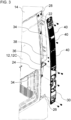
- the outer cover (or outer intake cover) 18 serves to cover an inlet 22 of an air intake duct 24 (see in particular Figure 3 ).
- the air intake duct 24 is attached, preferably elastically, decoupled to the cab shell 12, e.g., by means of rubber elements.
- the air intake duct 24 can have large manufacturing and assembly tolerances, since it can, for example, be formed as a plastic blow-molded part.
- the air intake duct 24 can draw in air through the outer cover 18 via the inlet 22.
- the drawn-in air can expediently be supplied to a drive device, e.g., an internal combustion engine, of the commercial vehicle, e.g., as combustion air.
- the outer cover 18 can be shell-shaped or strip-shaped.
- the outer cover 18 can extend between a fender region 26 and a roof region 28 of the cab shell 12 (see also Figure 3 ).
- the roof area 28 may still be part of the body and be arranged below a roof rim.
- the air intake duct 24 and/or the inlet 22 it is also possible for the air intake duct 24 and/or the inlet 22 to be arranged differently, preferably on the longitudinal outer side 12C of the cab shell 12.
- a special feature of the outer cover 18 is its attachment.
- the outer cover 18 is fixed to the driver's cab. Specifically, the outer cover 18 is firmly attached to the driver's cab shell 12. The outer cover 18 is decoupled from the inlet 22 and the air intake duct 24.
- the outer cover 18 can expediently be in two parts.
- the outer cover 18 can have a support part 30 and a cover part 32.
- the support part 30 is in the Figures 3 to 6
- the aperture part 32 is shown in the Figures 2 , 4 and 7 to 11
- the carrier part 30 supports the cover part 32.
- the cover part 32 covers the carrier part 30.
- the cover part 32 and the carrier part 30 can have substantially matching outer contours.
- the cover part 32 can preferably be attached to the carrier part 30 by means of a guide and/or plug connection, preferably in a manner that is not visible from the outside.
- Figure 3 shows an assembly of the support part 30.
- the support part 30 is firmly attached to the cab shell 12.
- the cab shell 12 can have at least one protruding area 34.
- the protruding area 34 can protrude in or opposite to the forward direction of travel.
- the protruding area 34 can be plate-shaped.
- the protruding area 34 can have a tongue shape or a tab shape. If there are several protruding areas 34, these can be spaced apart from one another in the vertical direction of the cab shell 12.
- at least one intermediate bracket 36 to be arranged between the cab shell 12 and the support part 30.
- the support part 30 is firmly attached to the protruding areas 34, the intermediate bracket 36, the roof area 28 and/or the fender area 26.
- the attachment can be detachable.
- screw connections can firmly attach the support part 30 to the cab shell 12, as in Figure 3 is shown by way of example.
- blind rivet nuts into which screws can be screwed can be inserted in the protruding areas 34, the roof area 28 and/or the fender area 26.
- the support part 30 is preferably not permanently attached to the inlet 22. Instead, decoupling from the inlet 22 is preferred.
- a preferably elastically deformable seal 38 e.g., a rubber seal, can be arranged between the inlet 22 and a rear side of the support part 30. The seal 38 seals against a surface of the support part 30 that is shaped and/or adapted to the seal 38.
- Figures 5 and 6 show that the carrier part 30 can have at least one grid area 40, at least one guide 42 and/or at least one locking element receptacle 44.
- the at least one grid area 40 protectively covers the inlet 22.
- the inlet 22 can draw air through the at least one grid area 40.
- the at least one grid area 40 can be designed, for example, as a perforated sheet.
- the panel part 32 can be attached to the support part 30 by means of the at least one guide 42 and the locking element receptacle 44.
- the guides 42 and the locking element receptacles 44 can be designed as cutouts.
- the guides 42 and the locking element receptacles 44 can be arranged in raised sections of a front side of the support part 30, e.g., to stiffen the support part 30.
- the guides 42 can be spaced apart from one another along a longitudinal axis of the support part 30.
- the locking element receptacles 44 can be spaced apart from one another along a longitudinal axis of the support part 30.
- the support part 30 is preferably designed as a single piece and/or in a strip shape.
- the at least one grid area 40, the at least one guide 42 and/or the at least one locking element receptacle 44 can be designed as an integral piece in the support part 30.
- the support part 30 is preferably a sheet metal part, particularly preferably a drawn sheet metal part.
- the support part 30 can extend between a fender area 26 and a roof area 28 of the driver's cab shell (see also Figure 3 ).
- the panel part 32 can have at least one guide element 46 and/or at least one locking element 48.
- the at least one guide element 46 is arranged on a rear side of the panel part 32.
- the at least one guide element 46 of the panel part 32 is connected to the at least a guide 42 of the support part 30.
- a number of guide elements 46 preferably corresponds to a number of guides 42.
- the at least one guide element 46 is, for example, hook-shaped or L-shaped (see Figures 10 and 11 ).
- the guide elements 46 can penetrate through the guides 42 designed as cutouts.
- the guide elements 46 are thus positioned on a rear side of the carrier part 30 or reach through the carrier part 30.
- the guide elements 46 guide the panel part 32 along the guides 42, support it on the carrier part 30 and engage behind the carrier part 30 with increasing displacement along the direction B.
- the guide elements 46 can thus already secure the panel part 32 on the carrier part 30 in a vertical direction and a transverse direction of the commercial vehicle.
- the at least one locking element 48 is arranged on a rear side of the cover part 32.
- the at least one locking element 48 of the cover part 32 is adapted to the at least one locking element receptacle 44 of the carrier part 30.
- a number of locking elements 48 preferably corresponds to a number of locking element receptacles 44.
- the at least one locking element 48 is, for example, dome-shaped (e.g., pin-shaped or cylinder-shell-shaped) (see Figure 10 ).
- the displacement of the panel part 32 along the support part 30 in the direction B in Figure 4 can be terminated by engaging the locking elements 48 in the locking element receptacles 44 designed as cutouts.
- the panel part 32 is locked along the direction B or along a longitudinal axis of the commercial vehicle on the carrier part 30.
- the panel part 32 is thus secured along the longitudinal axis, the transverse axis and the vertical axis of the commercial vehicle on the support part 30 by the interlocking of the guide elements 46 in the guides 42 and the locking elements 48 in the locking element receptacles 44.
- This securing is not visible from the outside.
- the securing is also in the reverse order than in Figure 4 shown can be removed again.
- a screw can be inserted through a screw receptacle 50 of the panel part 32 on the rear of the cab.
- the screw can be inserted into a corresponding screw receptacle 52 (see Figure 6 ) of the support part 30.
- the screw receptacles 50, 52 can be aligned and arranged such that the screw runs parallel to the forward direction of travel or the longitudinal axis of the commercial vehicle and is expediently only accessible and visible from the rear of the driver's cab.
- the screw receptacle 50 can be arranged on a rear side of the panel part 32.
- the screw receptacle 50 can have a screw hole that is aligned parallel to the forward direction of travel or the longitudinal axis of the commercial vehicle.
- the screw receptacle 52 can be arranged on a front side of the carrier part 30.
- the screw receptacle 52 can have a screw hole that is aligned parallel to the forward direction of travel or the longitudinal axis of the commercial vehicle.
- the screw holes of the screw receptacles 50, 52 can be aligned with one another when the panel part 32 is locked to the carrier part 30.
- the aperture part 32 has, for example, gill-shaped openings 54.
- the openings 54 are arranged in front of the grid areas 40 of the support part 30.
- the inlet 22 can draw air through the openings 54 and the grid areas 40.
- the panel part 32 is preferably designed as a single piece and/or in a strip shape.
- the at least one passage 54, the at least one guide element 46 and/or the at least one locking element 48 can be designed as an integral piece in the panel part 32.
- the panel part 32 is preferably a plastic part, particularly preferably an unpainted or at least externally painted plastic part.
- the panel part 32 can extend between a fender area 26 and a roof area 28 of the cab shell (see also Figure 3 ).
- the panel part 32 can have a plurality of support elements or spacer elements 56.
- the support elements 56 can be arranged on a rear side of the panel part 32.
- the support elements 56 can be spaced apart from one another, in particular with respect to a longitudinal axis of the panel part 32.
- the support elements 56 can, for example, be dome-shaped (e.g., cylindrical shell-shaped).
- the support part 30 can have support sections 58 adapted to the support elements 56.
- the support sections 58 can be arranged on a front side of the support part 30.
- the support sections 58 can be raised or dome-shaped, for example. Due to the raised shape/dome shape, the support sections 58 can also be visible as beads on a rear side of the support part 30.
- the panel part 32 When attached to one another, the panel part 32 can be supported by means of the support elements 56 on the support sections 58 of the carrier part 30.
- the support elements 56 can abut the support sections 58 when the locking elements 48 are received in the locking element receptacles 44.
- the support elements 56 and the support sections 58 can be arranged distributed over the entire length of the outer cover 18.
- the support part 30 has a stop buffer 60 (see Figure 6 ).
- the stop buffer 60 can be arranged on a rear side of the support part 30.
- the stop buffer 60 can be made of an elastically deformable material, e.g., a rubber material.
- the stop buffer 60 can be designed, for example, in the shape of a pin, plug, or pin.
- the stop buffer 60 can be aligned parallel to the forward direction of travel or the longitudinal axis of the commercial vehicle.
- the stop buffer 60 can limit and dampen a stop of the support part 30 when it is attached to the cab shell 12, in particular with regard to positioning relative to the forward direction of travel or the longitudinal axis of the commercial vehicle.
Landscapes
- Engineering & Computer Science (AREA)
- Mechanical Engineering (AREA)
- Chemical & Material Sciences (AREA)
- Combustion & Propulsion (AREA)
- Transportation (AREA)
- Body Structure For Vehicles (AREA)
Claims (14)
- Un véhicule utilitaire, de préférence un camion, comprenant :une structure (12) de cabine de conduite, ayant un côté extérieur longitudinal (12C) ;un conduit (24) d'admission d'air fixé à la structure (12) de la cabine de conduite et présentant une entrée (22) située sur le côté extérieur longitudinal (12C) ;etun couvercle extérieur (18) qui recouvre l'entrée (22) et qui est monté de manière fixe sur la structure (12) de la cabine de conduite ;caractérisé en ce que le couvercle extérieur (18) est découplé de l'entrée (22) et du conduit (24) d'admission d'air.
- Le véhicule utilitaire selon la revendication 1, comprenant en outre :
un joint d'étanchéité (38), de préférence élastiquement déformable, agencé entre l'entrée (22) et le couvercle extérieur (18). - Le véhicule utilitaire selon l'une des revendications précédentes, dans lequel :
le couvercle extérieur (18) comprend une partie support (30) et une partie de façade (32). - Le véhicule utilitaire selon la revendication 3, dans lequel :la partie support (30) est une pièce en tôle, de préférence une pièce en tôle emboutie ; et/ou la partie support (30) est en appui sur un joint d'étanchéité (38), de préférence élastiquement déformable, agencé entre l'entrée (22) et la partie support (30) ; et/oula partie support (30) présente au moins une zone de grille (40) qui recouvre l'entrée (22) ; et/ou la partie support (30) est essentiellement en forme de coque et/ou de bande ; et/oula partie support (30) est montée de manière fixe sur la structure (12) de la cabine de conduite, de préférence au moyen de plusieurs assemblages vissés.
- Le véhicule utilitaire selon la revendication 3 ou la revendication 4, dans lequel :la partie de façade (32) est une partie en matière plastique, de préférence non peinte ou peinte ; et/ou la partie de façade (32) présente au moins un passage (54), de préférence en forme d'ouïes, qui recouvre l'entrée (22) ; et/oula partie de façade (32) est essentiellement en forme de coque et/ou de bande.
- Le véhicule utilitaire selon l'une des revendications 3 à 5, dans lequel :la partie de façade (32) est portée par la partie support (30) ; et/oula partie de façade (32) est montée de manière amovible sur la partie support (30) ; et/oula partie de façade (32) est montée sur la partie support (30) au moyen d'une liaison de guidage et/ou d'enfichage amovible ; et/oula partie de façade (32) et la partie support (30) présentent des contours extérieurs qui coïncident pour l'essentiel entre eux.
- Le véhicule utilitaire selon l'une des revendications 3 à 6, dans lequel :la partie de façade (32) est guidée de manière coulissante sur la partie support (30), de préférence parallèlement à un axe longitudinal du véhicule utilitaire ; et/oula partie de façade (32) est apte à être bloquée sur la partie de support (30).
- Le véhicule utilitaire selon l'une des revendications 3 à 7, dans lequel :
la partie de façade (32) est montée sur la partie de support (30) au moyen d'un assemblage vissé (50, 52) visible uniquement depuis l'arrière de la cabine de conduite et/ou accessible uniquement depuis l'arrière de la cabine de conduite. - Le véhicule utilitaire selon l'une des revendications 3 à 8, dans lequel :
la partie de façade (32) présente au moins un élément de guidage (46), de préférence en forme de crochet ou de L, qui est inséré ou est apte à être inséré dans au moins un guide (42), de préférence découpé, de la partie support (30), de préférence parallèlement à un axe longitudinal du véhicule utilitaire. - Le véhicule utilitaire selon la revendication 9, dans lequel :
la partie de façade (32) présente au moins un élément d'arrêt (48), de préférence en forme de dôme, qui s'engage dans au moins un logement d'élément d'arrêt (44), de préférence découpé, de la partie de support (30), lorsque ledit au moins un élément de guidage (46) est inséré dans ledit au moins un guide (42). - Le véhicule utilitaire selon l'une des revendications 3 à 10, dans lequel :la partie de façade (32) présente au moins un élément d'appui (56), de préférence en forme de dôme, qui s'appuie sur au moins une portion d'appui (58), de préférence en relief, de la partie support (30) ; et/oula partie support (30) présente un tampon de butée (60), de préférence en forme de tige et/ou élastiquement déformable, qui délimite une butée contre la structure (12) de la cabine de conduite, de préférence par rapport à un axe longitudinal du véhicule utilitaire.
- Le véhicule utilitaire selon l'une des revendications précédentes, dans lequel :la structure (12) de la cabine de conduite présente au moins une zone (34) en saillie, de préférence en forme de plaque, de préférence parallèle à un axe longitudinal du véhicule utilitaire, sur laquelle le couvercle extérieur (18) est monté fixe ; et/oula structure (12) de la cabine de conduite présente une zone de toit (28) sur laquelle le couvercle extérieur (18) est fixé de manière rigide ; et/ou la structure (12) de la cabine de conduite présente une zone en forme d'aile (26) sur laquelle le couvercle extérieur (18) est monté de manière fixe.
- Le véhicule utilitaire selon l'une des revendications précédentes, dans lequel :le couvercle extérieur (18) est agencé derrière une porte (16) du véhicule utilitaire par rapport à un sens de marche avant du véhicule utilitaire ; et/ou le couvercle extérieur (18) s'étend entre une zone en forme d'aile (26) de la structure (12) de la cabine de conduite et une zone de toit de la structure (12) de la cabine de conduite ; et/oule couvercle extérieur (18) est agencé sur le côté extérieur longitudinal (12C) de la structure (12) de la cabine de conduite et/ou de manière adjacente à un côté arrière (12D) de la structure (12) de la cabine de conduite.
- Le véhicule utilitaire selon l'une des revendications précédentes, dans lequel :le conduit (24) d'admission d'air est monté de manière découplée sur la structure (12) de la cabine de conduite, de préférence élastiquement ; et/oule conduit (24) d'admission d'air est relié à un dispositif d'entraînement, de préférence un moteur à combustion interne, du véhicule utilitaire ; et/ou le conduit (24) d'admission d'air est agencé derrière une porte (16) du véhicule utilitaire par rapport au sens de marche avant du véhicule utilitaire.
Applications Claiming Priority (1)
| Application Number | Priority Date | Filing Date | Title |
|---|---|---|---|
| DE102020000736.8A DE102020000736A1 (de) | 2020-02-04 | 2020-02-04 | Nutzfahrzeug mit Luftansaugkanal und Außenabdeckung |
Publications (3)
| Publication Number | Publication Date |
|---|---|
| EP3862229A1 EP3862229A1 (fr) | 2021-08-11 |
| EP3862229C0 EP3862229C0 (fr) | 2025-04-02 |
| EP3862229B1 true EP3862229B1 (fr) | 2025-04-02 |
Family
ID=74184423
Family Applications (1)
| Application Number | Title | Priority Date | Filing Date |
|---|---|---|---|
| EP21151526.7A Active EP3862229B1 (fr) | 2020-02-04 | 2021-01-14 | Véhicule utilitaire pourvu de conduit d'admission d'air et de couvercle externe |
Country Status (2)
| Country | Link |
|---|---|
| EP (1) | EP3862229B1 (fr) |
| DE (1) | DE102020000736A1 (fr) |
Families Citing this family (1)
| Publication number | Priority date | Publication date | Assignee | Title |
|---|---|---|---|---|
| DE102021127615A1 (de) | 2021-10-25 | 2023-04-27 | Man Truck & Bus Se | Fahrerhaus und Verwendung eines Fahrerhauses |
Family Cites Families (4)
| Publication number | Priority date | Publication date | Assignee | Title |
|---|---|---|---|---|
| SE439751B (sv) | 1984-09-07 | 1985-07-01 | Saab Scania Ab | Luftinloppskanal vid ett med en forarhytt forsett lastfordon |
| DE9002753U1 (de) | 1990-03-09 | 1991-04-04 | Goldbecker Kunststoffplatten GmbH & Co KG, 4834 Harsewinkel | Fahrerhaus für Lastkraftwagen |
| US5042603A (en) * | 1990-04-23 | 1991-08-27 | Navistar International Transportation Corp. | Engine air intake apparatus |
| WO2009082272A1 (fr) * | 2007-12-20 | 2009-07-02 | Volvo Lastvagnar Ab | Module de conduit d'admission d'air pour un moteur |
-
2020
- 2020-02-04 DE DE102020000736.8A patent/DE102020000736A1/de active Pending
-
2021
- 2021-01-14 EP EP21151526.7A patent/EP3862229B1/fr active Active
Also Published As
| Publication number | Publication date |
|---|---|
| EP3862229C0 (fr) | 2025-04-02 |
| EP3862229A1 (fr) | 2021-08-11 |
| DE102020000736A1 (de) | 2021-08-05 |
Similar Documents
| Publication | Publication Date | Title |
|---|---|---|
| EP2014501B1 (fr) | Module avant pour véhicules | |
| DE10329624B4 (de) | Halterung für eine Kühlerverkleidung eines Fahrzeuges | |
| EP2719565B1 (fr) | Structure avant pour un véhicule automobile | |
| DE102007061812A1 (de) | Kraftfahrzeug mit einer Luftleitvorrichtung | |
| DE102017129199B4 (de) | Luftstrommanagementsystem für ein Fahrzeug | |
| EP2069187A1 (fr) | Élément porteur pour un module frontal d'un véhicule automobile | |
| EP3617040B1 (fr) | Module avant de cabine de conducteur et procédé de fabrication d'une cabine de conducteur | |
| DE10062686B4 (de) | Klimaanlage für ein Fahrzeug, insbesondere für einen Omnibus | |
| EP2399782B1 (fr) | Structure porteuse pour la fixation latérale de composants de construction sur un support longitudinal d'une structure porteuse de véhicule utilitaire | |
| EP2921327A2 (fr) | Cabine de conducteur d'une machine-outil à usage agricole ou dans les travaux publics | |
| DE19534972C2 (de) | Geräuschdämpfende Motorunterverkleidung | |
| EP3862229B1 (fr) | Véhicule utilitaire pourvu de conduit d'admission d'air et de couvercle externe | |
| DE102010051366A1 (de) | Tragstruktur für Karosserievorderbau eines Kraftfahrzeugs | |
| DE102005006250B3 (de) | Fahrzeugkarosserie eines Kraftwagens | |
| DE60017060T2 (de) | Vorder- Viertel- Befestigung auf Querträger | |
| EP3424805B1 (fr) | Cabine pour un engin agricole | |
| DE10233041A1 (de) | Heckpartie eines Kraftfahrzeugs | |
| DE19933283B4 (de) | Karosserievorderpartie | |
| DE2642110C2 (fr) | ||
| DE102014016766A1 (de) | Luftführungseinrichtung für einen Kraftwagen, insbesondere einen Personenkraftwagen | |
| EP3424759B1 (fr) | Toit d'une cabine pour un véhicule de travail agricole | |
| DE602005003268T2 (de) | Vorrichtung zur Verhinderung des Wassereintritts in einem Luftkanal eines Wasserkastens eines Kraftfahrzeuges, und ein selbiger Wasserkasten | |
| EP1595770B1 (fr) | Véhicule présentant un moyen de fixation pour une source lumineuse extérieure | |
| DE19634103C2 (de) | Spritzwasserfänger für Fahrzeuge | |
| DE102012015043B3 (de) | Luftansaugvorrichtung einer Brennkraftmaschine und Leitungsmodul einer solchen |
Legal Events
| Date | Code | Title | Description |
|---|---|---|---|
| PUAI | Public reference made under article 153(3) epc to a published international application that has entered the european phase |
Free format text: ORIGINAL CODE: 0009012 |
|
| STAA | Information on the status of an ep patent application or granted ep patent |
Free format text: STATUS: THE APPLICATION HAS BEEN PUBLISHED |
|
| AK | Designated contracting states |
Kind code of ref document: A1 Designated state(s): AL AT BE BG CH CY CZ DE DK EE ES FI FR GB GR HR HU IE IS IT LI LT LU LV MC MK MT NL NO PL PT RO RS SE SI SK SM TR |
|
| STAA | Information on the status of an ep patent application or granted ep patent |
Free format text: STATUS: REQUEST FOR EXAMINATION WAS MADE |
|
| 17P | Request for examination filed |
Effective date: 20220209 |
|
| RBV | Designated contracting states (corrected) |
Designated state(s): AL AT BE BG CH CY CZ DE DK EE ES FI FR GB GR HR HU IE IS IT LI LT LU LV MC MK MT NL NO PL PT RO RS SE SI SK SM TR |
|
| STAA | Information on the status of an ep patent application or granted ep patent |
Free format text: STATUS: EXAMINATION IS IN PROGRESS |
|
| 17Q | First examination report despatched |
Effective date: 20220608 |
|
| GRAP | Despatch of communication of intention to grant a patent |
Free format text: ORIGINAL CODE: EPIDOSNIGR1 |
|
| STAA | Information on the status of an ep patent application or granted ep patent |
Free format text: STATUS: GRANT OF PATENT IS INTENDED |
|
| INTG | Intention to grant announced |
Effective date: 20241023 |
|
| GRAS | Grant fee paid |
Free format text: ORIGINAL CODE: EPIDOSNIGR3 |
|
| GRAA | (expected) grant |
Free format text: ORIGINAL CODE: 0009210 |
|
| STAA | Information on the status of an ep patent application or granted ep patent |
Free format text: STATUS: THE PATENT HAS BEEN GRANTED |
|
| AK | Designated contracting states |
Kind code of ref document: B1 Designated state(s): AL AT BE BG CH CY CZ DE DK EE ES FI FR GB GR HR HU IE IS IT LI LT LU LV MC MK MT NL NO PL PT RO RS SE SI SK SM TR |
|
| REG | Reference to a national code |
Ref country code: GB Ref legal event code: FG4D Free format text: NOT ENGLISH |
|
| REG | Reference to a national code |
Ref country code: CH Ref legal event code: EP |
|
| REG | Reference to a national code |
Ref country code: IE Ref legal event code: FG4D Free format text: LANGUAGE OF EP DOCUMENT: GERMAN |
|
| REG | Reference to a national code |
Ref country code: DE Ref legal event code: R096 Ref document number: 502021007059 Country of ref document: DE |
|
| U01 | Request for unitary effect filed |
Effective date: 20250425 |
|
| U07 | Unitary effect registered |
Designated state(s): AT BE BG DE DK EE FI FR IT LT LU LV MT NL PT RO SE SI Effective date: 20250527 |
|
| PG25 | Lapsed in a contracting state [announced via postgrant information from national office to epo] |
Ref country code: ES Free format text: LAPSE BECAUSE OF FAILURE TO SUBMIT A TRANSLATION OF THE DESCRIPTION OR TO PAY THE FEE WITHIN THE PRESCRIBED TIME-LIMIT Effective date: 20250402 |
|
| PG25 | Lapsed in a contracting state [announced via postgrant information from national office to epo] |
Ref country code: NO Free format text: LAPSE BECAUSE OF FAILURE TO SUBMIT A TRANSLATION OF THE DESCRIPTION OR TO PAY THE FEE WITHIN THE PRESCRIBED TIME-LIMIT Effective date: 20250702 Ref country code: GR Free format text: LAPSE BECAUSE OF FAILURE TO SUBMIT A TRANSLATION OF THE DESCRIPTION OR TO PAY THE FEE WITHIN THE PRESCRIBED TIME-LIMIT Effective date: 20250703 |
|
| PG25 | Lapsed in a contracting state [announced via postgrant information from national office to epo] |
Ref country code: PL Free format text: LAPSE BECAUSE OF FAILURE TO SUBMIT A TRANSLATION OF THE DESCRIPTION OR TO PAY THE FEE WITHIN THE PRESCRIBED TIME-LIMIT Effective date: 20250402 |
|
| PG25 | Lapsed in a contracting state [announced via postgrant information from national office to epo] |
Ref country code: HR Free format text: LAPSE BECAUSE OF FAILURE TO SUBMIT A TRANSLATION OF THE DESCRIPTION OR TO PAY THE FEE WITHIN THE PRESCRIBED TIME-LIMIT Effective date: 20250402 |
|
| PG25 | Lapsed in a contracting state [announced via postgrant information from national office to epo] |
Ref country code: RS Free format text: LAPSE BECAUSE OF FAILURE TO SUBMIT A TRANSLATION OF THE DESCRIPTION OR TO PAY THE FEE WITHIN THE PRESCRIBED TIME-LIMIT Effective date: 20250702 |
|
| PG25 | Lapsed in a contracting state [announced via postgrant information from national office to epo] |
Ref country code: IS Free format text: LAPSE BECAUSE OF FAILURE TO SUBMIT A TRANSLATION OF THE DESCRIPTION OR TO PAY THE FEE WITHIN THE PRESCRIBED TIME-LIMIT Effective date: 20250802 |
|
| PG25 | Lapsed in a contracting state [announced via postgrant information from national office to epo] |
Ref country code: SM Free format text: LAPSE BECAUSE OF FAILURE TO SUBMIT A TRANSLATION OF THE DESCRIPTION OR TO PAY THE FEE WITHIN THE PRESCRIBED TIME-LIMIT Effective date: 20250402 |
|
| PG25 | Lapsed in a contracting state [announced via postgrant information from national office to epo] |
Ref country code: CZ Free format text: LAPSE BECAUSE OF FAILURE TO SUBMIT A TRANSLATION OF THE DESCRIPTION OR TO PAY THE FEE WITHIN THE PRESCRIBED TIME-LIMIT Effective date: 20250402 |
|
| PG25 | Lapsed in a contracting state [announced via postgrant information from national office to epo] |
Ref country code: SK Free format text: LAPSE BECAUSE OF FAILURE TO SUBMIT A TRANSLATION OF THE DESCRIPTION OR TO PAY THE FEE WITHIN THE PRESCRIBED TIME-LIMIT Effective date: 20250402 |
|
| PLBE | No opposition filed within time limit |
Free format text: ORIGINAL CODE: 0009261 |
|
| STAA | Information on the status of an ep patent application or granted ep patent |
Free format text: STATUS: NO OPPOSITION FILED WITHIN TIME LIMIT |
|
| REG | Reference to a national code |
Ref country code: CH Ref legal event code: L10 Free format text: ST27 STATUS EVENT CODE: U-0-0-L10-L00 (AS PROVIDED BY THE NATIONAL OFFICE) Effective date: 20260211 |
|
| U20 | Renewal fee for the european patent with unitary effect paid |
Year of fee payment: 6 Effective date: 20260126 |
|
| 26N | No opposition filed |
Effective date: 20260105 |