EP3862575A1 - Carter de compresseur avec structure de recirculation, compresseur comprenant le carter de compresseur, et turbocompresseur comprenant le compresseur - Google Patents
Carter de compresseur avec structure de recirculation, compresseur comprenant le carter de compresseur, et turbocompresseur comprenant le compresseur Download PDFInfo
- Publication number
- EP3862575A1 EP3862575A1 EP21150694.4A EP21150694A EP3862575A1 EP 3862575 A1 EP3862575 A1 EP 3862575A1 EP 21150694 A EP21150694 A EP 21150694A EP 3862575 A1 EP3862575 A1 EP 3862575A1
- Authority
- EP
- European Patent Office
- Prior art keywords
- groove portion
- impeller
- compressor
- compressor housing
- end portion
- Prior art date
- Legal status (The legal status is an assumption and is not a legal conclusion. Google has not performed a legal analysis and makes no representation as to the accuracy of the status listed.)
- Withdrawn
Links
- 238000011144 upstream manufacturing Methods 0.000 claims abstract description 166
- 230000007246 mechanism Effects 0.000 claims description 16
- 230000010349 pulsation Effects 0.000 abstract description 23
- 238000002485 combustion reaction Methods 0.000 abstract description 16
- 230000001629 suppression Effects 0.000 abstract description 10
- 239000007789 gas Substances 0.000 description 71
- 238000011161 development Methods 0.000 description 31
- 238000010586 diagram Methods 0.000 description 16
- 230000009471 action Effects 0.000 description 8
- 238000004891 communication Methods 0.000 description 8
- 230000003247 decreasing effect Effects 0.000 description 5
- 230000000694 effects Effects 0.000 description 4
- 230000002411 adverse Effects 0.000 description 3
- 230000009467 reduction Effects 0.000 description 3
- 238000005206 flow analysis Methods 0.000 description 2
- 230000006870 function Effects 0.000 description 2
- 230000002452 interceptive effect Effects 0.000 description 2
- 230000002093 peripheral effect Effects 0.000 description 2
- 238000012360 testing method Methods 0.000 description 2
- 239000000567 combustion gas Substances 0.000 description 1
- 230000005484 gravity Effects 0.000 description 1
- 239000000463 material Substances 0.000 description 1
- 238000000034 method Methods 0.000 description 1
- 230000004048 modification Effects 0.000 description 1
- 238000012986 modification Methods 0.000 description 1
- 238000010248 power generation Methods 0.000 description 1
Images







Classifications
-
- F—MECHANICAL ENGINEERING; LIGHTING; HEATING; WEAPONS; BLASTING
- F04—POSITIVE - DISPLACEMENT MACHINES FOR LIQUIDS; PUMPS FOR LIQUIDS OR ELASTIC FLUIDS
- F04D—NON-POSITIVE-DISPLACEMENT PUMPS
- F04D29/00—Details, component parts, or accessories
- F04D29/66—Combating cavitation, whirls, noise, vibration or the like; Balancing
- F04D29/68—Combating cavitation, whirls, noise, vibration or the like; Balancing by influencing boundary layers
- F04D29/681—Combating cavitation, whirls, noise, vibration or the like; Balancing by influencing boundary layers especially adapted for elastic fluid pumps
- F04D29/685—Inducing localised fluid recirculation in the stator-rotor interface
-
- F—MECHANICAL ENGINEERING; LIGHTING; HEATING; WEAPONS; BLASTING
- F04—POSITIVE - DISPLACEMENT MACHINES FOR LIQUIDS; PUMPS FOR LIQUIDS OR ELASTIC FLUIDS
- F04D—NON-POSITIVE-DISPLACEMENT PUMPS
- F04D29/00—Details, component parts, or accessories
- F04D29/40—Casings; Connections of working fluid
- F04D29/42—Casings; Connections of working fluid for radial or helico-centrifugal pumps
- F04D29/44—Fluid-guiding means, e.g. diffusers
- F04D29/441—Fluid-guiding means, e.g. diffusers especially adapted for elastic fluid pumps
-
- F—MECHANICAL ENGINEERING; LIGHTING; HEATING; WEAPONS; BLASTING
- F04—POSITIVE - DISPLACEMENT MACHINES FOR LIQUIDS; PUMPS FOR LIQUIDS OR ELASTIC FLUIDS
- F04D—NON-POSITIVE-DISPLACEMENT PUMPS
- F04D29/00—Details, component parts, or accessories
- F04D29/26—Rotors specially for elastic fluids
- F04D29/28—Rotors specially for elastic fluids for centrifugal or helico-centrifugal pumps for radial-flow or helico-centrifugal pumps
- F04D29/284—Rotors specially for elastic fluids for centrifugal or helico-centrifugal pumps for radial-flow or helico-centrifugal pumps for compressors
-
- F—MECHANICAL ENGINEERING; LIGHTING; HEATING; WEAPONS; BLASTING
- F04—POSITIVE - DISPLACEMENT MACHINES FOR LIQUIDS; PUMPS FOR LIQUIDS OR ELASTIC FLUIDS
- F04D—NON-POSITIVE-DISPLACEMENT PUMPS
- F04D29/00—Details, component parts, or accessories
- F04D29/40—Casings; Connections of working fluid
- F04D29/42—Casings; Connections of working fluid for radial or helico-centrifugal pumps
- F04D29/4206—Casings; Connections of working fluid for radial or helico-centrifugal pumps especially adapted for elastic fluid pumps
- F04D29/4213—Casings; Connections of working fluid for radial or helico-centrifugal pumps especially adapted for elastic fluid pumps suction ports
-
- F—MECHANICAL ENGINEERING; LIGHTING; HEATING; WEAPONS; BLASTING
- F04—POSITIVE - DISPLACEMENT MACHINES FOR LIQUIDS; PUMPS FOR LIQUIDS OR ELASTIC FLUIDS
- F04D—NON-POSITIVE-DISPLACEMENT PUMPS
- F04D29/00—Details, component parts, or accessories
- F04D29/66—Combating cavitation, whirls, noise, vibration or the like; Balancing
- F04D29/661—Combating cavitation, whirls, noise, vibration or the like; Balancing especially adapted for elastic fluid pumps
- F04D29/667—Combating cavitation, whirls, noise, vibration or the like; Balancing especially adapted for elastic fluid pumps by influencing the flow pattern, e.g. suppression of turbulence
-
- F—MECHANICAL ENGINEERING; LIGHTING; HEATING; WEAPONS; BLASTING
- F05—INDEXING SCHEMES RELATING TO ENGINES OR PUMPS IN VARIOUS SUBCLASSES OF CLASSES F01-F04
- F05D—INDEXING SCHEME FOR ASPECTS RELATING TO NON-POSITIVE-DISPLACEMENT MACHINES OR ENGINES, GAS-TURBINES OR JET-PROPULSION PLANTS
- F05D2220/00—Application
- F05D2220/40—Application in turbochargers
-
- F—MECHANICAL ENGINEERING; LIGHTING; HEATING; WEAPONS; BLASTING
- F05—INDEXING SCHEMES RELATING TO ENGINES OR PUMPS IN VARIOUS SUBCLASSES OF CLASSES F01-F04
- F05D—INDEXING SCHEME FOR ASPECTS RELATING TO NON-POSITIVE-DISPLACEMENT MACHINES OR ENGINES, GAS-TURBINES OR JET-PROPULSION PLANTS
- F05D2250/00—Geometry
- F05D2250/50—Inlet or outlet
- F05D2250/51—Inlet
-
- F—MECHANICAL ENGINEERING; LIGHTING; HEATING; WEAPONS; BLASTING
- F05—INDEXING SCHEMES RELATING TO ENGINES OR PUMPS IN VARIOUS SUBCLASSES OF CLASSES F01-F04
- F05D—INDEXING SCHEME FOR ASPECTS RELATING TO NON-POSITIVE-DISPLACEMENT MACHINES OR ENGINES, GAS-TURBINES OR JET-PROPULSION PLANTS
- F05D2250/00—Geometry
- F05D2250/50—Inlet or outlet
- F05D2250/52—Outlet
Definitions
- the present disclosure relates to a compressor housing, a compressor including the compressor housing, and a turbocharger including the compressor.
- Engines used in automobiles and the like may be equipped with a turbocharger to improve engine output.
- the turbocharger rotates an impeller of a compressor connected to a turbine rotor via a rotation shaft by rotating the turbine rotor using exhaust gas from an engine.
- the turbocharger compresses gas used for engine combustion by means of the impeller that is rotationally driven, and supplies the resultant gas to the engine.
- a centrifugal compressor used in a turbocharger includes an impeller and a compressor housing that houses the impeller.
- the impeller guides the gas flowing in from the front side in the axial direction to the outer side in the radial direction.
- Components formed in the compressor housing include: an intake flow path through which gas is guided from the outside of the compressor housing toward the front side in the axial direction of the impeller; an impeller chamber that is in communication with the intake flow path and accommodates the impeller; and a scroll flow path, in communication with the impeller chamber, through which the gas that has passed through the impeller is guided to the outside of the compressor housing.
- Such a compressor preferably has a wide range, that is, a high pressure ratio to be achieved over a wide operation range.
- an unstable phenomenon known as surging mass gas vibration in the flow direction of the gas
- the operation range of the compressor is limited under the low flow rate condition.
- a method for suppressing surging has been studied for the purpose of achieving a wide range in a low flow rate range.
- Patent Document 1 discloses a centrifugal compressor 011 including a compressor housing 04 with a recirculation flow path 043 formed therein.
- the recirculation flow path 043 has a first end portion side connected to an impeller chamber 041 that houses an impeller 03 and a second end portion side connected to an intake flow path 042 positioned further upstream than the impeller chamber 041, as illustrated in FIG. 14 .
- Such a compressor 011 can suppress surging even when the flow rate of the gas flowing from the outside of the compressor housing 04 to the impeller chamber 041 through the intake flow path 042 is low, because the flow volume of the gas sent to the inlet side of the impeller 03 can be increased when a part of the gas inside the impeller chamber 041 returns to the impeller chamber 041 through the recirculation flow path 043 and the intake flow path 042.
- a compressor used for a turbocharger has a downstream side, in the flow direction of gas, connected to an engine, and thus is exposed to pressure pulsation due to air intake of the engine. This results in the gas flowing in the compressor housing being in a form of a non-steady flow with pulsation. This flow is known to provide a surging suppressing effect which is not obtained by a constant flow without pulsation.
- Patent Document 1 WO 2011/099419 A
- FR1 FR2 + FR3
- FR1 represents the flow rate of gas flowing into the impeller 03 in the impeller chamber 041
- FR2 represents the flow rate of the intake gas that flows in the intake flow path 042 after flowing in from the outside of the compressor housing 04
- FR3 represents the flow rate of the recirculation flow flowing to the intake flow path 042 from the impeller chamber 041 through the recirculation flow path 043.
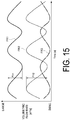
- the phase of the flow rate FR3 of the recirculation flow driven by the difference in pressure between the inlet and the outlet of the recirculation flow path 043 differs from that of the intake flow rate FR2.
- the intake flow rate FR2 and the flow rate FR3 of the recirculation flow having phases different from each other are combined, resulting in an amplitude FV1 of the flow rate FR1 of the gas flowing into the impeller 03 being smaller than an amplitude FV2 of the intake flow rate FR2.
- the intake flow rate FR2 and the flow rate FR3 of the recirculation flow interfere with each other on the inlet side of the impeller 03 such that their pulsations offset each other.
- the surging suppression effect by pulsation is lost.
- an object of at least one embodiment of the present disclosure is to provide a compressor housing, a compressor, and a turbocharger with which a wider range over a low flow rate range can be achieved without compromising a surging suppression effect achieved by pulsation of an internal combustion engine provided on the downstream side of the compressor.
- a compressor housing configured to rotatably house an impeller including a hub and a plurality of blades provided on an outer surface of the hub, the compressor housing including:
- a compressor according to the present disclosure includes:
- a turbocharger according to the present disclosure includes:
- a compressor housing, a compressor, and a turbocharger are provided with which a wider range over a low flow rate range can be achieved without compromising a surging suppression effect achieved by pulsation of an internal combustion engine provided on the downstream side of the compressor.
- an expression of relative or absolute arrangement such as “in a direction”, “along a direction”, “parallel”, “orthogonal”, “centered”, “concentric” and “coaxial” shall not be construed as indicating only the arrangement in a strict literal sense, but also includes a state where the arrangement is relatively displaced by a tolerance, or by an angle or a distance whereby it is possible to achieve the same function.
- an expression of an equal state such as “same” “equal” and “uniform” shall not be construed as indicating only the state in which the feature is strictly equal, but also includes a state in which there is a tolerance or a difference that can still achieve the same function.
- an expression of a shape such as a rectangular shape or a cylindrical shape shall not be construed as only the geometrically strict shape, but also includes a shape with unevenness or chamfered corners within the range in which the same effect can be achieved.
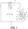
- FIG. 1 is an explanatory diagram illustrating a configuration of a turbocharger according to an embodiment of the present disclosure.
- a turbocharger 1 includes a compressor 11, a turbine 12, and a rotation shaft 13, as illustrated in FIG. 1 .
- the compressor 11 includes an impeller 3 and a compressor housing 4 configured to rotatably house the impeller 3.
- the turbine 12 includes a turbine rotor 14 connected to the impeller 3 via the rotation shaft 13, and a turbine housing 15 configured to rotatably house the turbine rotor 14.
- the turbocharger 1 is a turbocharger for an automobile. Note that some embodiments of the present disclosure may be applied to a turbocharger other than a turbocharger for an automobile (for example, a turbocharger for power generation or marine vessels).
- the turbocharger 1 further includes a bearing 16 that rotatably supports the rotation shaft 13, and a bearing housing 17 configured to accommodate the bearing 16, as illustrated in FIG. 1 .
- the bearing housing 17 is disposed between the compressor housing 4 and the turbine housing 15, and is mechanically connected to the compressor housing 4 and the turbine housing 15 by a fastening member such as a fastening bolt or a V clamp.
- an extending direction of an axis CA of the impeller 3 housed in the compressor housing 4 is defined as an axial direction X
- a direction orthogonal to the axis CA is defined as a radial direction Y.
- a side on which a gas introduction port 44 is positioned relative to the impeller 3 is defined as a front side XF
- a side on which the impeller 3 is positioned relative to the gas introduction port 44 is defined as a rear side XR.
- the gas introduction port 44 through which gas from the outside of the compressor housing 4 is introduced, and a gas discharge port 45 through which gas that has passed through the impeller 3 is discharged to the outside of the compressor housing 4 to be sent to an internal combustion engine 2 (for example, an engine) are formed in the compressor housing 4.
- an exhaust gas introduction port 151 through which exhaust gas is introduced into the turbine housing 15, and an exhaust gas discharge port 152 through which exhaust gas that has rotated the turbine rotor 14 is discharged to the outside of the turbine housing 15 along the axial direction X are formed in the turbine housing 15.
- the rotation shaft 13 has a longitudinal direction extending along the axial direction X, as illustrated in FIG. 1 .
- the impeller 3 is mechanically connected to a first end portion 131 (end portion on the front side XF) in the longitudinal direction of the rotation shaft 13, and the turbine rotor 14 is mechanically connected to a second end portion 132 (end portion on the rear side XR) in the longitudinal direction of the rotation shaft 13.
- the impeller 3 is provided to be coaxial with the turbine rotor 14.
- the phrase "along a certain direction" not only includes the certain direction but also includes a direction that is inclined with respect to the certain direction (e.g., within ⁇ 45° relative to the certain direction).
- the impeller 3 is provided on a supply line 21 through which gas (for example, combustion gas such as air) is supplied to the internal combustion engine 2.
- gas for example, combustion gas such as air
- the turbine rotor 14 is provided on an exhaust line 22 through which the exhaust gas discharged from the internal combustion engine 2 is discharged.
- the turbocharger 1 rotates the turbine rotor 14 using the exhaust gas introduced from the internal combustion engine 2 into the turbine housing 15 through the exhaust line 22.
- the impeller 3 is mechanically connected to the turbine rotor 14 via the rotation shaft 13, and thus is rotated by the rotation of the turbine rotor 14.
- the turbocharger 1 compresses gas introduced into the compressor housing 4 through the supply line 21 by rotating the impeller 3, and transmits the resultant gas to the internal combustion engine 2.
- FIG. 2 is a schematic cross-sectional view schematically illustrating a compressor side of the turbocharger including the compressor according to one embodiment of the present disclosure, and is a schematic cross-sectional view including an axis of the compressor housing.
- the impeller 3 of the compressor 11 includes a hub 31 and a plurality of blades 32 provided on an outer surface 311 of the hub 31, as illustrated in FIG. 2 .
- the hub 31 is mechanically affixed to the first end portion 131 of the rotatable shaft 13, whereby the hub 31 and the plurality of blades 32 are provided to the rotation shaft 13 to be integrally rotatable about the rotational axis of the rotatable shaft 13.
- the impeller 3 is configured to guide the gas sent from the front side XF in the axial direction X to the outer side in the radial direction Y.
- the outer surface 311 of the hub 31 is formed into a recessed curved shape such that a distance from the rotational axis increases toward the rear side XR from the front side XF in the axial direction X, and is formed on the front side XF in the axial direction X.
- the plurality of blades 32 are disposed at intervals in the circumferential direction about the rotational axis.
- the plurality of blades 32 include a plurality of long blades (full blades) 33 extending from an inlet part 411 to an outlet part 412 for the gas of the impeller chamber 41 housing the impeller 3, and a plurality of short blades (splitter blades) 34 having a shorter extending length than the long blades 33.
- the long blades 33 and the short blades 34 are disposed alternately in the circumferential direction.
- the long blades 33 and the short blades 34 are formed to have a three-dimensionally curved plate shape.
- Each of the plurality of short blades 34 extends to the outlet part 412 from a portion more on the downstream side than a leading edge 331, which is an edge of the long blade 33 on the side of the inlet part 411, in each flow path for the gas formed between adjacent long blades 33, 33 on the outer surface 311 of the hub 31.
- each of the plurality of long blades 33 has the leading edge 331, which is the edge on the side of the inlet part 411, a trailing edge 332 that is an edge on the side of the outlet part 412, a hub side edge 333 that is an edge on the side connected to the hub 31, and a tip side edge 334 that is an edge opposite to the hub side edge 333.
- Each of the plurality of short blades 34 has a leading edge 341 that is an edge on the side of the inlet part 411, a trailing edge 342 that is an edge on the side of the outlet part 412, a hub side edge 343 that is an edge on the side connected to the hub 3 1, and a tip side edge 344 that is an edge opposite to the hub side edge 343.
- a gap is formed between each of the tip side edges 334 and 344 and a shroud surface 46 of the compressor housing 4.
- the impeller 3 may only include the long blades 33.
- the compressor housing 4 includes an intake flow path-forming section 420 that forms an intake flow path 42 through which gas from the outside of the compressor housing 4 is introduced to the impeller 3, a shroud portion 460 having a shroud surface 46 curved in a protruding manner to face the blades 32 (specifically, the tip side edges 334 and 344) of the impeller 3, and a scroll flow path-forming section 470 that forms a scroll flow path 47 through which the gas that has passed through the impeller 3 is guided to the outside of the compressor housing 4.
- Each of the intake flow path 42 and the scroll flow path 47 is formed inside the compressor housing 4. Note that the recirculation flow path 043 as illustrated in FIG. 14 is not formed in the compressor housing 4.
- the compressor housing 4 is configured to form the impeller chamber 41 that rotatably houses the impeller 3 and a diffuser flow path 48 through which the gas from the impeller 3 is guided to the scroll flow path 47, by being combined with another member (such as the bearing housing 17).
- upstream side in the flow direction of the gas flowing inside the compressor housing 4 may be simply referred to as the "upstream side”
- downstream side in the flow direction of the gas may be simply referred to as the "downstream side”.
- the intake flow path 42 extends along the axial direction X, and has one end on the front side XF in communication with the gas introduction port 44 positioned further upstream than the intake flow path 42 and an other end on the rear side XR in communication with the inlet part 411 of the impeller chamber 41 positioned further downstream than the intake flow path 42.
- the diffuser flow path 48 extends along a direction intersecting (orthogonal to, for example) the axial direction X, and has one end on the inner side in the radial direction in communication with the outlet part 412 of the impeller chamber 41 positioned further upstream than the diffuser flow path 48, and has another end on the outer side in the radial direction in communication with the scroll flow path 47 positioned further downstream than the diffuser flow path 48.
- the scroll flow path 47 has a spiral shape surrounding the periphery of the impeller 3 (the outer side in the radial direction Y) and is in communication with the gas discharge port 45 (see FIG. 1 ) positioned further downstream than the scroll flow path 47.
- the gas is introduced into the compressor housing 4 through the gas introduction port 44 of the compressor housing 4 and then flows in the intake flow path 42 toward the rear side XR along the axial direction X to be sent to the impeller 3.
- the gas sent to the impeller 3 flows in the diffuser flow path 48 and the scroll flow path 47 in this order, and then is discharged to the outside of the compressor housing 4 through the gas discharge port 45.
- the intake flow path-forming section 420 is formed into a tubular shape having the intake flow path 42 therein.
- the intake flow path-forming section 420 includes an inner wall surface 421 that extends along the axial direction X and defines the intake flow path 42.
- the gas introduction port 44 is formed at an end portion of the intake flow path-forming section 420 on the front side XF.
- the scroll flow path-forming section 470 includes a scroll inner wall surface 471 that defines the scroll flow path 47.
- the shroud portion 460 is provided between the intake flow path-forming section 420 and the scroll flow path-forming section 470.
- the shroud surface 46 of the shroud portion 460 defines a portion, on the front side XF, of the impeller chamber 41 described above.
- the shroud surface 46 faces each of the tip side edges 334 and 344 of the impeller 3.
- a portion of the impeller chamber 41 on the rear side XR is defined by members other than the compressor housing 4, such as an end surface 171 of the bearing housing 17 on the front side XF.
- FIG. 3 is an enlarged schematic cross-sectional view of the vicinity of the shroud surface in FIG. 2 .
- the at least one groove portion 5 extending along the circumferential direction is formed in the shroud surface 46 of the compressor housing 4.
- the at least one groove portion 5 includes a downstream side wall surface 6, the distance to which from the axis CA increases from a downstream side end portion 51 of the groove portion 5 toward the upstream side (left side in the figure), and an upstream side curved surface 7 formed to be curved in a recessed manner between an upstream end 61 of the downstream side wall surface 6 and an upstream side end portion 52 of the groove portion 5.
- a most upstream position 71 of the upstream side curved surface 7 is configured to be positioned further upstream than the upstream side end portion 52.
- the downstream side wall surface 6 includes a downstream side curved surface 6A that is curved in a recessed manner toward the outer side in the radial direction. Note that in some other embodiments, the downstream side wall surface 6 may extend linearly, or may be curved in a recessed manner toward the inner side in the radial direction.
- the upstream side curved surface 7 includes a first upstream side curved surface 72 provided between the most upstream position 71 and the upstream side end portion 52 of the groove portion 5, and a second upstream side curved surface 73 provided between the most upstream position 71 and the upstream end 61 of the downstream side wall surface 6.
- the first upstream side curved surface 72 is curved in a recessed manner toward the inner side in the radial direction such that the distance between the first upstream side curved surface 72 and the axis CA increases toward the upstream side (front side XF), and has an upstream end at the upstream side end portion 52 of the groove portion 5 and a downstream end at the most upstream position 71.
- the second upstream side curved surface 73 is curved in a recessed manner toward the outer side in the radial direction such that the distance between the second upstream side curved surface 73 and the axis CA increases toward the downstream side (rear side XR), and has an upstream end at the most upstream position 71 and a downstream end at the upstream end 61 of the downstream side wall surface 6.
- the second upstream side curved surface 73 is connected to the first upstream side curved surface 72 at the most upstream position 71.
- the second upstream side curved surface 73 (the upstream side curved surface 7) is connected to the downstream side wall surface 6 at a deepest position 74.
- the groove portion 5 may further include a linear or curved surface connecting the upstream end of the first upstream side curved surface 72 and the upstream side end portion 52 of the groove portion 5, and may further include a linear or curved surface connecting the downstream end of the second upstream side curved surface 73 and the upstream end 61 of the downstream side wall surface 6.
- FIG. 4 is an explanatory diagram illustrating how gas flows in the compressor under a low flow rate condition, and illustrates the results of a non-steady flow analysis of a pulsating flow.
- the gas introduced to the impeller 3 is separated from the shroud surface 46 and the blades 32 of the impeller 3 due to an adverse pressure gradient, whereby a backflow range RB is formed near the shroud surface 46 and a backflow F2 (flow toward the front side XF in the axial direction X) flowing along the shroud surface 46 is produced in the backflow range RB.
- This backflow F2 merges with a main flow F1 of the gas introduced to the impeller 3 in the vicinity of the inlet (leading edge 331) of the impeller 3, and is then introduced again to the impeller 3.
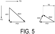
- FIG. 5 is an explanatory diagram illustrating how gas flows in the compressor under the low flow rate condition, and illustrates the velocity triangle of the gas introduced to the impeller illustrated in FIG. 4 and the velocity triangle of the backflow flowing in the vicinity of the shroud surface.
- the flow direction of the main flow F1 of the gas introduced to the impeller 3 is defined as FD
- a tangential direction of the impeller 3 is defined as TD
- the main flow F1 forms a velocity triangle comprising an absolute velocity AS1, a relative velocity RD1, and peripheral speed PS1.
- the backflow F2 flowing along the shroud surface 46 forms a velocity triangle comprising an absolute velocity AS2, a relative velocity RD2, and the peripheral speed PS1.
- the backflow F2 involves strong centrifugal action provided by significant tangential speed TS due to the rotation of impeller 3.
- the backflow F2 flowing along the shroud surface 46 is provided with the tangential speed TS due to the rotation of the impeller 3.
- the centrifugal action provided by the tangential speed TS causes the backflow F2 to flow along the downstream side wall surface 6 and enter the groove portion 5.
- the upstream side curved surface 7 is curved in a recessed manner. In the upstream side curved surface 7, the most upstream position 71 is positioned further upstream than the upstream side end portion 52.
- the backflow F2 that has entered the groove portion 5 can have its flow direction turned around to flow toward the rear side XR from the front side XF in the axial direction with the speed maintained, so as to be sent to the vicinity of the shroud surface 46.
- At least one groove portion 5 extending along the circumferential direction is formed in the shroud surface 46 of the compressor housing 4 according to some embodiments.
- the at least one groove portion 5 described above includes the downstream side wall surface 6 described above and the upstream side curved surface 7 described above.
- the most upstream position 71 of the upstream side curved surface 7 is configured to be positioned further upstream than the upstream side end portion 52.
- the at least one groove portion 5 formed in the shroud surface 46 includes the downstream side wall surface 6, the distance to which from the axis CA increases toward the upstream side from the downstream side end portion 51, and the upstream side curved surface 7 formed between the upstream side end portion 52 and the upstream end 61 of the downstream side wall surface 6.
- the gas introduced to the impeller 3 is separated from the shroud surface 46 and the blades 32 of the impeller 3 due to the adverse pressure gradient, whereby the backflow F2 (flow towards the front side XF in the axial direction X) is produced in the vicinity of the shroud surface 46.
- This backflow F2 is provided with the tangential speed TS due to the rotation of the impeller 3.
- the centrifugal action provided by the tangential speed TS causes the backflow F2 to flow along the downstream side wall surface 6 and enter the groove portion 5.
- the upstream side curved surface 7 is curved in a recessed manner. In the upstream side curved surface 7, the most upstream position 71 is positioned further upstream than the upstream side end portion 52.
- the backflow F2 that has entered the groove portion 5 can have its flow direction turned around to flow toward the rear side XR from the front side XF in the axial direction with the speed maintained, so as to be sent to the vicinity of the shroud surface 46.
- the downstream side wall surface 6 described above includes the downstream side curved surface 6A that is curved in a recessed manner toward the outer side in the radial direction and has a curvature smaller than that of the upstream side curved surface 7.
- the downstream side wall surface 6 includes the downstream side curved surface 6A that is curved in a recessed manner toward the outer side in the radial direction.
- the distance between the downstream side wall surface 6 and the axis CA between the upstream end 61 of the downstream side curved surface 6A and the downstream side end portion 51 of the groove portion 5 can be increased compared with cases where the downstream side wall surface 6 extends linearly or is curved in a protruding manner.
- the downstream side curved surface 6A is gently curved with a curvature C6A thereof being smaller than a curvature C7 of the upstream side curved surface 7 to facilitate the entrance of the backflow F2 into the groove portion 5 along the downstream side curved surface 6A, whereby the flow rate of the backflow F2 turned around by the groove portion 5 can be increased.
- the at least one groove portion 5 described above includes a ring-shaped groove 5A that extends over the entire circumference in the circumferential direction.
- the backflow F2 can be turned around by the ring-shaped groove 5A anywhere along the entire circumference in the circumferential direction.
- the development of the backflow range RB in the vicinity of the shroud surface 46 can be prevented over the entire circumference in the circumferential direction.
- FIG. 6 is an enlarged schematic cross-sectional view of the vicinity of the shroud surface in FIG. 2 .
- FIG. 7 is an explanatory diagram illustrating Examples of a compressor housing according to an embodiment of the present disclosure.
- the at least one groove portion 5 described above is configured to have a center 53 positioned between the leading edge 331 and the trailing edge 332 of the long blade 33 (the blade 32) in the extending direction (axial direction X) of the axis CA, in a cross-sectional view taken along the axis CA of the impeller 3.
- the center 53 refers to the center of figure (center of gravity) of the groove portion 5 in the cross-sectional view described above.
- the at least one groove portion 5 is configured to satisfy 0.2 ⁇ Z/L ⁇ 1.2, where L represents the distance from a hub end 335 of the trailing edge 332 of the long blade 33 (blade 32) to a tip end 336 of the leading edge 331 in the axial direction X, and Z represents a distance from the hub end 335 to the upstream side end portion 52 of the groove portion 5 in the same direction, in the cross-sectional view taken along the axis CA as illustrated in FIG. 6 .
- the at least one groove portion 5 is configured to satisfy a condition of 0.3 ⁇ Z/L ⁇ 1.1.
- the groove portion 5 is configured in such a manner that the leading edge 331 of the long blade 33 is positioned between the downstream side end portion 51 and the upstream side end portion 52 in the axial direction X in the cross-sectional view taken along the axis CA. Specifically, in the cross-sectional view described above, the groove portion 5 is configured such that the center 53 is positioned at an axial direction position corresponding to the leading edge 331 of the long blade 33.
- the groove portion 5 is configured in such a manner that a throat portion 35 of the long blade 33 is positioned between the downstream side end portion 51 and the upstream side end portion 52 in the axial direction X in the cross-sectional view taken along the axis CA.
- the groove portion 5 is configured such that the center 53 is positioned at an axial direction position corresponding to the throat portion 35 of the long blade 33.
- the throat portion 35 is a portion where the width of the long blades 33 disposed adjacent to each other along the circumferential direction is minimized.
- the throat portion 35 is positioned between the leading edge 331 of the long blade 33 and the leading edge 341 of the short blade 34 in the axial direction X.
- the groove portion 5 is configured in such a manner that the leading edge 341 of the short blade 34 is positioned between the downstream side end portion 51 and the upstream side end portion 52 in the axial direction X in the cross-sectional view taken along the axis CA. Specifically, in the cross-sectional view described above, the groove portion 5 is configured such that the center 53 is positioned at an axial direction position corresponding to the leading edge 341 of the short blade 34.
- the groove portion 5 is configured in such a manner that a throat portion 36 of the short blade 34 is positioned between the downstream side end portion 51 and the upstream side end portion 52 in the axial direction X in the cross-sectional view taken along the axis CA.
- the groove portion 5 is configured such that the center 53 is positioned at an axial direction position corresponding to the throat portion 36 of the short blade 34.
- the throat portion 36 is a portion where the width of the long blades 33 and the short blades 34 disposed adjacent to each other along the circumferential direction is minimized.
- the throat portion 36 is positioned between the leading edge 341 and the trailing edge 342 of the short blade 34 in the extending direction of the axis CA.
- the center 53 of the at least one groove portion 5 is positioned between the leading edge 331 and the trailing edge 332 of the blade 32 in the extending direction of the axis CA.
- a test for pulsating flow was performed to acquire the pressure flow rate characteristics of the compressors 11.
- the result of the test indicated that a surging flow rate, which indicates the operating limit on the lower flow rate side, was reduced (up to 6.1% reduction), compared to that in compressors including compressor housings without the groove portion 5 or the recirculation flow path.
- a wide range of the compressor 11 under pulsation was confirmed.
- the at least one groove portion 5 was configured to satisfy a condition of 5° ⁇ ⁇ 1 ⁇ 45°, where ⁇ 1 represents an inclination angle of the upstream side curved surface 7 relative to a first normal N1 passing through the upstream side end portion 52 of the shroud surface 46 described above.
- the at least one groove portion 5 is configured to satisfy a condition 10° ⁇ ⁇ 1 ⁇ 40°.
- the at least one groove portion 5 was configured to satisfy a condition of 15° ⁇ ⁇ 2 ⁇ 30°, where ⁇ 2 represents an inclination angle of the downstream side wall surface 6 relative to a second normal N2 passing through the downstream side end portion 51 of the shroud surface 46 described above.
- the groove portion 5 is configured such that at least one of the leading edge 331 and the throat portion 35 of the long blade 33 is positioned between the downstream side end portion 51 and the upstream side end portion 52 in the axial direction X.
- the groove portion 5 is configured to satisfy a condition of ⁇ 1 ⁇ ⁇ 2.
- the groove portion 5 is configured such that at least one of the leading edge 341 and the throat portion 36 of the short blade 34 is positioned between the downstream side end portion 51 and the upstream side end portion 52 in the axial direction X.
- the groove portion 5 is configured to satisfy a condition of ⁇ 1 > ⁇ 2.
- the inclination angle ⁇ 1 of the upstream side curved surface 7 of the at least one groove portion 5 satisfies the condition of 5° ⁇ ⁇ 1 ⁇ 45°.
- the backflow F2 exiting the groove portion 5 along the upstream side curved surface 7 the development of the backflow range RB in the vicinity of the shroud surface 46 can be effectively suppressed.
- the inclination angle ⁇ 1 is less than 5°, the speed component toward the inner side in the radial direction of the backflow F2 that has exited the groove portion 5 along the upstream side curved surface 7 becomes excessively large and the flow rate of the flow toward the vicinity of the shroud surface 46 becomes small.
- the development of the backflow range RB in the vicinity of the shroud surface 46 may fail to be sufficiently suppressed.
- the inclination angle ⁇ 1 is greater than 45°, the speed component toward the inner side in the radial direction of the backflow F2 that has exited the groove portion 5 along the upstream side curved surface 7 becomes excessively small and the backflow F2 that has exited the groove portion 5 along the upstream side curved surface 7 may interfere with the backflow F2 entering the groove portion 5 along the downstream side wall surface 6.
- these flows may offset each other.
- the at least one groove portion 5 was configured to satisfy a condition of 0.50 ⁇ W/H ⁇ 0.85, where H represents a distance from the upstream side end portion 52 to the downstream side end portion 51 of the at least one groove portion 5 in the extending direction of the axis CA (the axial direction X), and W represents the maximum depth of the at least one groove portion 5.
- H represents a distance from the upstream side end portion 52 to the downstream side end portion 51 of the at least one groove portion 5 in the extending direction of the axis CA (the axial direction X)
- W represents the maximum depth of the at least one groove portion 5.
- the at least one groove portion 5 was configured to satisfy the condition of 0.55 ⁇ W/H ⁇ 0.80. More preferably, the at least one groove portion 5 was configured to satisfy the condition of 0.60 ⁇ W/H ⁇ 0.75.
- the at least one groove portion 5 satisfies the condition of 0.50 ⁇ W/H ⁇ 0.85.
- the development of the backflow range RB in the vicinity of the shroud surface 46 can be effectively suppressed. If the ratio W/H of the maximum depth W to the distance H is less than 0.5, the maximum depth W becomes too small, and the backflow F2 that has exited the groove portion 5 along the upstream side curved surface 7 may interfere with the backflow F2 entering the groove portion 5 along the downstream side wall surface 6. Thus, these flows may offset each other.
- the ratio W/H of the maximum depth W to the distance H exceeds 0.85, the maximum depth W becomes too large, and it becomes difficult for the backflow F2 that has entered the groove portion 5 to flow along the downstream side wall surface 6 or the upstream side curved surface 7. Thus, the turned-around flow may fail to be formed.
- the at least one groove portion 5 was configured to satisfy a condition of 0.10 ⁇ H/R ⁇ 0.30, where H represents a distance from the upstream side end portion 52 to the downstream side end portion 51 of the at least one groove portion 5 in the extending direction of the axis CA (the axial direction X), and R represents the distance from the axis CA to the upstream side end portion 52 in the direction (radial direction Y) orthogonal to the axis CA.
- the at least one groove portion 5 was configured to satisfy the condition of 0.14 ⁇ H/R ⁇ 0.26. More preferably, the at least one groove portion 5 was configured to satisfy the condition of 0.18 ⁇ H/R ⁇ 0.22.
- the at least one groove portion 5 satisfies the condition of 0.10 ⁇ H/R ⁇ 0.30, so that an appropriate ratio between the flow rate of the main flow F1 of the gas flowing into the impeller 3 and the flow rate of the backflow F2 flowing into the groove portion 5 can be achieved.
- an appropriate ratio between the flow rate of the main flow F1 of the gas flowing into the impeller 3 and the flow rate of the backflow F2 flowing into the groove portion 5 can be achieved.
- the entrance of the backflow F2 into the groove portion 5 is facilitated, whereby the development of the backflow range RB in the vicinity of the shroud surface 46 can be effectively suppressed.
- FIG. 8 is an explanatory diagram illustrating the shape of a groove portion according to an embodiment of the present disclosure.
- FIG. 9 is a schematic cross-sectional view schematically illustrating an AB cross section of an inclined groove illustrated in FIG. 8 .
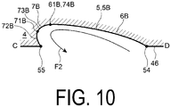
- FIG. 10 is a schematic cross-sectional view schematically illustrating a CD cross section of the inclined groove illustrated in FIG. 8 .
- the at least one groove portion 5 described above includes a plurality of inclined grooves 5B that extend partially over the entire circumference in the circumferential direction in a direction inclined with respect to the circumferential direction, and are formed at intervals along the circumferential direction.
- the leading edge 331 of one of two inclined grooves 5B adjacent to each other in the circumferential direction is positioned at a circumferential position corresponding to the trailing edge 332 of the other inclined groove 5B.
- two inclined grooves 5B adjacent to each other in the circumferential direction may overlap each other in the circumferential direction.
- each of the plurality of inclined grooves 5B includes the downstream side wall surface 6 (for example, the downstream side curved surface 6A) described above and the upstream side curved surface 7 described above.
- the plurality of inclined grooves 5B are formed at intervals along the circumferential direction of the shroud surface 46.
- the backflow F2 can be turned around by the plurality of inclined grooves 5B partially over the entire circumference in the circumferential direction.
- the development of the backflow range RB in the vicinity of the shroud surface 46 can be prevented partially over the entire circumference in the circumferential direction.
- each of the plurality of inclined grooves 5B described above is configured to have an end portion 54 on the trailing edge side (downstream side in the flow direction FD of the main flow F1) positioned further downstream (the right side in the figure) than an end portion 55 on the leading edge side (upstream side of the flow direction FD of the main flow F1) in the rotational direction (the tangential direction TD) of the impeller 3.
- each of the plurality of inclined grooves 5B has a longitudinal direction extending along a direction of a velocity vector of the relative velocity RD2 of the backflow F2.
- the end portion 54 on the trailing edge side is positioned further downstream than the end portion 55 on the leading edge side in the rotational direction of the impeller 3.
- each of the plurality of inclined grooves 5B includes a trailing edge side wall surface 6B, a distance to which from the axis CA increases toward the end portion 55 on the leading edge side from the end portion 54 on the trailing edge side of the inclined groove 5B, and a leading edge side curved surface 7B formed to be curved in a recessed manner between the leading edge 61B of the trailing edge side wall surface 6B and the end portion 55 on the leading edge side and that is configured to have a most upstream position 71B positioned more on the leading edge side of the inclined groove 5B than the end portion 55 of the leading edge side, in a cross-sectional view taken along the extending direction of the inclined groove 5B as illustrated in FIG. 10 .
- the trailing edge side wall surface 6B includes a trailing edge side curved surface that is curved in a recessed manner toward the outer side in the radial direction (upper side in FIG. 10 ). Note that in some other embodiments, the trailing edge side wall surface 6B may extend linearly or may be curved in a recessed manner toward the inner side in the radial direction.
- the leading edge side curved surface 7B includes a first leading edge side curved surface 72B provided between the most upstream position 71B and the end portion 55 of the inclined groove 5B on the leading edge side, and a second leading edge side curved surface 73B provided between the most upstream position 71B and the leading edge 61B of the trailing edge side wall surface 6B.
- the first leading edge side curved surface 72B is curved in a recessed manner toward the inner side in the radial direction such that the distance between the first leading edge side curved surface 72B and the axis CA increases toward the leading edge side of the inclined groove 5B (downstream side in the flow direction of the backflow F2).
- the upstream end of the first leading edge side curved surface 72B is the end portion 55 of the inclined groove 5B on the leading edge side and the downstream end of the first leading edge side curved surface 72B is the most upstream position 71B.
- the second leading edge side curved surface 73B is curved in a recessed manner toward the outer side in the radial direction such that the distance between the second leading edge side curved surface 73B and the axis CA increases toward the trailing edge side of the inclined groove 5B (upstream side in the flow direction of the backflow F2).
- the upstream end of the second leading edge side curved surface 73B is the most upstream position 71B and the downstream end of the second leading edge side curved surface 73B is the leading edge 61B of the trailing edge side wall surface 6B.
- the second leading edge side curved surface 73B is connected to the first leading edge side curved surface 72B at the most upstream position 71B.
- the second leading edge side curved surface 73B (the leading edge side curved surface 7B) is connected to the trailing edge side wall surface 6B at a deepest position 74B.
- the inclined groove 5B may further include a linear or curved surface connecting the upstream end of the first leading edge side curved surface 72B and the end portion 55 of the inclined groove 5B on the leading edge side, and may further include a linear or curved surface connecting the downstream end of the second leading edge side curved surface 73B and the leading edge 61B of the trailing edge side wall surface 6B.
- each of the plurality of inclined grooves 5B includes the trailing edge side wall surface 6B in a cross-sectional view taken along the extending direction of the inclined groove 5B, that is, the direction along the flow direction of the backflow F2.
- the entrance of the backflow F2 into the inclined groove 5B along the trailing edge side wall surface 6B is facilitated, whereby the flow rate of the backflow F2 turned around by the inclined groove 5B can be increased.
- Each of the plurality of inclined grooves 5B includes the trailing edge side wall surface 6B and the leading edge side curved surface 7B in the cross-sectional view described above.
- the backflow F2 that has entered the inclined groove 5B flows along the trailing edge side wall surface 6B and the leading edge side curved surface 7B, and thus can be sent to the vicinity of the shroud surface 46 after having the flow direction turned around while maintaining speed. According to the configuration described above, the development of the backflow range RB in the vicinity of the shroud surface 46 can be suppressed effectively.
- FIG. 11 is an explanatory diagram illustrating the shape of a groove portion according to an embodiment of the present disclosure, and schematically illustrates a compressor as viewed from the front side.
- FIG. 12 is a diagram illustrating the relationship between an angular position illustrated in FIG. 11 and a cross-sectional area of the groove portion.
- the at least one groove portion 5 described above includes the ring-shaped groove 5A.
- the ring-shaped groove 5A was configured to have the largest cross-sectional area in an angular range from an angular position of 0° to an angular position of 120° in the circumferential direction, where the angular position of a tongue portion 472 of the scroll flow path-forming section 470 in the circumferential direction of the impeller 3 is defined as 0°, and a downstream direction (clockwise direction) in the rotational direction (tangential direction TD) of the impeller 3 is defined as a positive direction of the angular position in the circumferential direction.
- This "cross-sectional area” refers to an opening area of the ring-shaped groove 5A in a cross section taken along the axis CA of the ring-shaped groove 5A.
- the cross-sectional area of the ring-shaped groove 5A in the circumferential direction is increased and decreased by increasing and decreasing the maximum depth W in the circumferential direction.
- the maximum depth W and the cross-sectional area of each ring-shaped groove 5A reach a maximum at one angular position AP1 located within an angular range from an angular position of 90° to an angular position of 120° in the circumferential direction, and reach a minimum at one angular position AP2 located within an angular range from an angular position of 270° to angular position of 300° in the circumferential direction.
- Each ring-shaped groove 5A is configured to have the maximum depth W and the cross-sectional area gradually decreasing in both the clockwise direction and the counterclockwise direction between the angular positions AP1 to AP2.
- the cross-sectional area in the circumferential direction may be increased and decreased by increasing and decreasing the distance H from the upstream side end portion 52 to the downstream side end portion 51 in the circumferential direction.
- the backflow F2 is not uniform in the circumferential direction, and is large at a certain portion in the circumferential direction (an angular range from an angular position of 0° to an angular position of 120° in the circumferential direction) compared with other portions.
- the cross-sectional area of each ring-shaped groove 5A is not uniform in the circumferential direction, and reaches a maximum in the angular range from the angular position of 0° to the angular position of 120° in the circumferential direction.
- the compressor 11 includes the above-described impeller 3 including at least the hub 31 and the plurality of blades 32, and the compressor housing 4 having the above-described at least one groove portion 5 formed in the shroud surface 46.
- the at least one groove portion 5 formed in the shroud surface 46 of the compressor housing 4 can suppress surging under the low flow rate condition, whereby the operation range of the compressor 11 can be expanded in the low flow rate range.
- the above-described configuration does not hinder the pulsation of gas introduced to the impeller 3, and thus a surging suppression effect can be provided by the pulsation of the internal combustion engine 2 on the downstream side of the compressor 11.
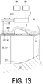
- FIG. 13 is a schematic cross-sectional view schematically illustrating a compressor side of the turbocharger including the compressor according to one embodiment of the present disclosure, and is a schematic cross-sectional view including an axis of the compressor housing.
- the above-described compressor 11 further includes a groove portion opening/closing device 9 including a cover 91 that covers the groove portion 5 in an openable/closable manner, and an opening/closing mechanism unit 92 configured to perform opening and closing operations for the cover 91.
- the cover 91 is composed of a tubular-shaped body disposed on an inner side of the inner wall surface 421 in the radial direction, and has an outer surface 911 in sliding contact with the inner wall surface 421.
- the opening/closing mechanism unit 92 is composed of an actuator (for example, an air cylinder) including a drive shaft 921 that is movable in forward and backward directions using air supplied from the outside.
- the opening/closing mechanism unit 92 is arranged such that the drive shaft 921 extends along the axial direction X.
- the groove portion opening/closing device 9 includes a rod-shaped connecting member 93 having a first end portion side connected to the outer surface 911 of the cover 91 and having a second end portion side connected to the drive shaft 921, an air supply source 94 used for supplying air to the opening/closing mechanism unit 92, and an opening/closing instruction device 95 configured to issue a drive instruction for the drive shaft 921 to the opening/closing mechanism unit 92 in accordance with the operating range of the compressor 11.
- the opening/closing mechanism unit 92 causes the drive shaft 921 to move forward and backward using air supplied from the air supply source 94.
- the cover 91 is moved in conjunction with the forward and backward movement of the drive shaft 921, via the connecting member 93, to open and close the groove portion 5.
- the opening/closing instruction device 95 is an electronic control unit used for controlling the opening and closing operations for the cover 91 by using the opening/closing mechanism unit 92, and may be configured as a microcomputer including a CPU (processor), a memory such as a ROM and a RAM, a storage device such as an external storage device, an I/O interface, and a communication interface, which are not illustrated.
- the CPU may operate (for example, perform a data operation or the like) in accordance with, for example, program instructions loaded into the main storage device of the memory to control the opening and closing operations for the cover 91 by using the opening/closing mechanism unit 92.
- the opening/closing instruction device 95 has pre-stored information associating an operating range of the compressor 11 (for example, the operating range on a compressor map) with the opening/closing instruction to the opening/closing mechanism unit 92, and is configured to identify the operation range of the compressor 11 based on the information input from the compressor 11 and issue the opening/closing instruction corresponding to the operation range to the opening/closing mechanism unit 92.
- the opening/closing mechanism unit 92 drives the drive shaft 921 to open/close the cover 91 in accordance with the instruction issued from the opening/closing instruction device 95.
- the compressor 11 includes the groove portion opening/closing device 9 including the cover 91 that covers the groove portion 5 in an openable/closable manner, and the opening/closing mechanism unit 92 configured to perform opening and closing operations for the cover 91.
- the groove portion 5 is opened by opening the cover 91 in an operating range in which surging is likely to occur in the operating range of the compressor 11.
- the development of the backflow range RB in the vicinity of the shroud surface 46 can be suppressed, whereby the operation range of the compressor 11 can be expanded.
- the cover 91 is closed to close the groove portion 5.
- the gap between the compressor housing 4 and the impeller 3 is made small, whereby efficiency reduction of the compressor 11 due to the gap can be suppressed.
- the turbocharger 1 described above includes the above-described compressor 11 and the turbine 12 including the turbine rotor 14 connected to the impeller 3 of the compressor 11 via the rotation shaft 13.
- the at least one groove portion 5 formed in the shroud surface 46 of the compressor housing 4 can suppress the development of the backflow range and surging under the low flow rate condition, whereby the operation range of the compressor 11 can be expanded in the low flow rate range.
- the above-described configuration does not hinder the pulsation of gas introduced to the impeller 3, and thus a surging suppression effect can be provided by the pulsation of the internal combustion engine 2 on the downstream side of the compressor 11.
- the at least one groove (5) formed in the shroud surface (46) of the compressor housing (4) can suppress the development of the backflow range and the surging under the low flow rate condition, whereby the operation range of the compressor (11) can be expanded in the low flow rate range.
- the above-described configuration does not hinder the pulsation of gas introduced to the impeller (3), whereby the surging suppression effect can be provided by the pulsation of the internal combustion engine (2) on the downstream side of the compressor (11).
Landscapes
- Engineering & Computer Science (AREA)
- Mechanical Engineering (AREA)
- General Engineering & Computer Science (AREA)
- Structures Of Non-Positive Displacement Pumps (AREA)
- Supercharger (AREA)
Applications Claiming Priority (1)
| Application Number | Priority Date | Filing Date | Title |
|---|---|---|---|
| JP2020018612A JP2021124069A (ja) | 2020-02-06 | 2020-02-06 | コンプレッサハウジング、該コンプレッサハウジングを備えるコンプレッサ、および該コンプレッサを備えるターボチャージャ |
Publications (1)
| Publication Number | Publication Date |
|---|---|
| EP3862575A1 true EP3862575A1 (fr) | 2021-08-11 |
Family
ID=74125081
Family Applications (1)
| Application Number | Title | Priority Date | Filing Date |
|---|---|---|---|
| EP21150694.4A Withdrawn EP3862575A1 (fr) | 2020-02-06 | 2021-01-08 | Carter de compresseur avec structure de recirculation, compresseur comprenant le carter de compresseur, et turbocompresseur comprenant le compresseur |
Country Status (4)
| Country | Link |
|---|---|
| US (1) | US11530708B2 (fr) |
| EP (1) | EP3862575A1 (fr) |
| JP (1) | JP2021124069A (fr) |
| CN (1) | CN113217469B (fr) |
Families Citing this family (14)
| Publication number | Priority date | Publication date | Assignee | Title |
|---|---|---|---|---|
| CN115717612B (zh) * | 2022-12-09 | 2025-09-16 | 清华大学 | 离心压气机的跨分流叶片自循环处理机匣和离心压气机 |
| CN115962153B (zh) * | 2023-03-17 | 2023-06-23 | 潍柴动力股份有限公司 | 过渡段子午流道宽度变窄的压气机和发动机 |
| US12078070B1 (en) | 2023-08-16 | 2024-09-03 | Rolls-Royce North American Technologies Inc. | Adjustable air flow plenum with sliding doors for a fan of a gas turbine engine |
| US12066035B1 (en) | 2023-08-16 | 2024-08-20 | Rolls-Royce North American Technologies Inc. | Adjustable depth tip treatment with axial member with pockets for a fan of a gas turbine engine |
| US11970985B1 (en) | 2023-08-16 | 2024-04-30 | Rolls-Royce North American Technologies Inc. | Adjustable air flow plenum with pivoting vanes for a fan of a gas turbine engine |
| US12085021B1 (en) | 2023-08-16 | 2024-09-10 | Rolls-Royce North American Technologies Inc. | Adjustable air flow plenum with movable closure for a fan of a gas turbine engine |
| US11965528B1 (en) | 2023-08-16 | 2024-04-23 | Rolls-Royce North American Technologies Inc. | Adjustable air flow plenum with circumferential movable closure for a fan of a gas turbine engine |
| US12018621B1 (en) | 2023-08-16 | 2024-06-25 | Rolls-Royce North American Technologies Inc. | Adjustable depth tip treatment with rotatable ring with pockets for a fan of a gas turbine engine |
| US12258870B1 (en) | 2024-03-08 | 2025-03-25 | Rolls-Royce North American Technologies Inc. | Adjustable fan track liner with slotted array active fan tip treatment for distortion tolerance |
| US12286936B1 (en) | 2024-05-09 | 2025-04-29 | Rolls-Royce North American Technologies Inc. | Adjustable fan track liner with groove array active fan tip treatment for distortion tolerance |
| US12209541B1 (en) | 2024-05-09 | 2025-01-28 | Rolls-Royce North American Technologies Inc. | Adjustable fan track liner with dual slotted array active fan tip treatment for distortion tolerance |
| US12215712B1 (en) | 2024-05-09 | 2025-02-04 | Rolls-Royce North American Technologies Inc. | Adjustable fan track liner with dual grooved array active fan tip treatment for distortion tolerance |
| US12168983B1 (en) | 2024-06-28 | 2024-12-17 | Rolls-Royce North American Technologies Inc. | Active fan tip treatment using rotating drum array in fan track liner with axial and circumferential channels for distortion tolerance |
| US12209502B1 (en) | 2024-06-28 | 2025-01-28 | Rolls-Royce North American Technologies Inc. | Active fan tip treatment using rotating drum array with axial channels in fan track liner for distortion tolerance |
Citations (9)
| Publication number | Priority date | Publication date | Assignee | Title |
|---|---|---|---|---|
| JPS63128298U (fr) * | 1987-10-22 | 1988-08-22 | ||
| US20030138317A1 (en) * | 1998-12-10 | 2003-07-24 | Mark Barnett | Casing treatment for a fluid compressor |
| DE10223876A1 (de) * | 2002-05-29 | 2003-12-11 | Daimler Chrysler Ag | Verdichter für eine Brennkraftmaschine |
| US20090246007A1 (en) * | 2008-02-28 | 2009-10-01 | Erik Johann | Casing treatment for axial compressors in a hub area |
| WO2011099419A1 (fr) | 2010-02-09 | 2011-08-18 | 株式会社Ihi | Compresseur centrifuge faisant appel à un traitement pour carter de recirculation automatique asymétrique |
| US20120321440A1 (en) * | 2010-02-09 | 2012-12-20 | Tsinghua University | Centrifugal compressor having an asymmetric self-recirculating casing treatment |
| US20140377053A1 (en) * | 2012-01-23 | 2014-12-25 | Ihi Corporation | Centrifugal compressor |
| CN105351240A (zh) * | 2015-12-14 | 2016-02-24 | 中国北方发动机研究所(天津) | 一种宽流量范围喘振控制的涡轮增压器压气机 |
| JP2019094847A (ja) * | 2017-11-24 | 2019-06-20 | 三菱重工業株式会社 | 圧縮機 |
Family Cites Families (13)
| Publication number | Priority date | Publication date | Assignee | Title |
|---|---|---|---|---|
| JPS5039673B2 (fr) | 1972-02-04 | 1975-12-18 | ||
| CH675279A5 (fr) * | 1988-06-29 | 1990-09-14 | Asea Brown Boveri | |
| CZ48394A3 (en) * | 1993-03-04 | 1994-09-14 | Abb Management Ag | Radial-flow compressor with a flow-stabilizing casing |
| JP3646625B2 (ja) * | 2000-06-01 | 2005-05-11 | 日産自動車株式会社 | 燃料改質装置 |
| US7775759B2 (en) * | 2003-12-24 | 2010-08-17 | Honeywell International Inc. | Centrifugal compressor with surge control, and associated method |
| EP2171283A4 (fr) * | 2007-02-14 | 2013-01-30 | Borgwarner Inc | Carter de compresseur |
| DE102008010283A1 (de) * | 2008-02-21 | 2009-08-27 | Mtu Aero Engines Gmbh | Zirkulationsstruktur für einen Turboverdichter |
| JP5039673B2 (ja) | 2008-02-27 | 2012-10-03 | 三菱重工業株式会社 | ターボ型圧縮機のストラット構造 |
| DE102008031982A1 (de) * | 2008-07-07 | 2010-01-14 | Rolls-Royce Deutschland Ltd & Co Kg | Strömungsarbeitsmaschine mit Nut an einem Laufspalt eines Schaufelendes |
| JP5479021B2 (ja) * | 2009-10-16 | 2014-04-23 | 三菱重工業株式会社 | 排気ターボ過給機のコンプレッサ |
| US10047620B2 (en) * | 2014-12-16 | 2018-08-14 | General Electric Company | Circumferentially varying axial compressor endwall treatment for controlling leakage flow therein |
| WO2018146753A1 (fr) * | 2017-02-08 | 2018-08-16 | 三菱重工エンジン&ターボチャージャ株式会社 | Compresseur centrifuge et turbocompresseur |
| EP3734081A1 (fr) * | 2019-04-30 | 2020-11-04 | Borgwarner Inc. | Dispositif de modification de flux pour compresseurs |
-
2020
- 2020-02-06 JP JP2020018612A patent/JP2021124069A/ja active Pending
-
2021
- 2021-01-08 EP EP21150694.4A patent/EP3862575A1/fr not_active Withdrawn
- 2021-01-11 CN CN202110029867.XA patent/CN113217469B/zh active Active
- 2021-01-15 US US17/150,141 patent/US11530708B2/en active Active
Patent Citations (9)
| Publication number | Priority date | Publication date | Assignee | Title |
|---|---|---|---|---|
| JPS63128298U (fr) * | 1987-10-22 | 1988-08-22 | ||
| US20030138317A1 (en) * | 1998-12-10 | 2003-07-24 | Mark Barnett | Casing treatment for a fluid compressor |
| DE10223876A1 (de) * | 2002-05-29 | 2003-12-11 | Daimler Chrysler Ag | Verdichter für eine Brennkraftmaschine |
| US20090246007A1 (en) * | 2008-02-28 | 2009-10-01 | Erik Johann | Casing treatment for axial compressors in a hub area |
| WO2011099419A1 (fr) | 2010-02-09 | 2011-08-18 | 株式会社Ihi | Compresseur centrifuge faisant appel à un traitement pour carter de recirculation automatique asymétrique |
| US20120321440A1 (en) * | 2010-02-09 | 2012-12-20 | Tsinghua University | Centrifugal compressor having an asymmetric self-recirculating casing treatment |
| US20140377053A1 (en) * | 2012-01-23 | 2014-12-25 | Ihi Corporation | Centrifugal compressor |
| CN105351240A (zh) * | 2015-12-14 | 2016-02-24 | 中国北方发动机研究所(天津) | 一种宽流量范围喘振控制的涡轮增压器压气机 |
| JP2019094847A (ja) * | 2017-11-24 | 2019-06-20 | 三菱重工業株式会社 | 圧縮機 |
Also Published As
| Publication number | Publication date |
|---|---|
| JP2021124069A (ja) | 2021-08-30 |
| CN113217469A (zh) | 2021-08-06 |
| CN113217469B (zh) | 2023-06-13 |
| US20210246908A1 (en) | 2021-08-12 |
| US11530708B2 (en) | 2022-12-20 |
Similar Documents
| Publication | Publication Date | Title |
|---|---|---|
| EP3862575A1 (fr) | Carter de compresseur avec structure de recirculation, compresseur comprenant le carter de compresseur, et turbocompresseur comprenant le compresseur | |
| EP2863064B1 (fr) | Compresseur centrifuge | |
| EP2960528B1 (fr) | Compresseur centrifuge | |
| CN107816440B (zh) | 离心压缩机 | |
| JP5221985B2 (ja) | 遠心圧縮機 | |
| CN107208658B (zh) | 离心压缩机及增压器 | |
| EP3421811A1 (fr) | Roue de compresseur et turbocompresseur | |
| KR102852859B1 (ko) | 컴프레서 케이싱, 과급기 및 과급기의 운전 방법 | |
| CN115667730A (zh) | 压缩机壳体和离心压缩机 | |
| JP2015040505A (ja) | 遠心圧縮機及び過給機 | |
| US11988227B2 (en) | Compressor housing and centrifugal compressor | |
| EP3712438A1 (fr) | Roue de compresseur, compresseur et turbocompresseur | |
| CN115135884B (zh) | 涡旋壳体以及离心压缩机 | |
| JP7232352B2 (ja) | コンプレッサおよび該コンプレッサを備えるターボチャージャ | |
| CN110234888A (zh) | 压缩机的涡旋形状以及增压器 | |
| US11047393B1 (en) | Multi-stage centrifugal compressor, casing, and return vane | |
| JP2012087709A (ja) | ターボ形圧縮機 | |
| CN110234855A (zh) | 排气涡轮增压器用涡轮的壳体、排气涡轮增压器用涡轮及制造方法 | |
| JP2025087955A (ja) | 遠心圧縮機のケーシング、遠心圧縮機及びターボチャージャ | |
| US20220196030A1 (en) | Variable geometry turbine and supercharger |
Legal Events
| Date | Code | Title | Description |
|---|---|---|---|
| PUAI | Public reference made under article 153(3) epc to a published international application that has entered the european phase |
Free format text: ORIGINAL CODE: 0009012 |
|
| STAA | Information on the status of an ep patent application or granted ep patent |
Free format text: STATUS: THE APPLICATION HAS BEEN PUBLISHED |
|
| AK | Designated contracting states |
Kind code of ref document: A1 Designated state(s): AL AT BE BG CH CY CZ DE DK EE ES FI FR GB GR HR HU IE IS IT LI LT LU LV MC MK MT NL NO PL PT RO RS SE SI SK SM TR |
|
| STAA | Information on the status of an ep patent application or granted ep patent |
Free format text: STATUS: REQUEST FOR EXAMINATION WAS MADE |
|
| 17P | Request for examination filed |
Effective date: 20220120 |
|
| RBV | Designated contracting states (corrected) |
Designated state(s): AL AT BE BG CH CY CZ DE DK EE ES FI FR GB GR HR HU IE IS IT LI LT LU LV MC MK MT NL NO PL PT RO RS SE SI SK SM TR |
|
| STAA | Information on the status of an ep patent application or granted ep patent |
Free format text: STATUS: EXAMINATION IS IN PROGRESS |
|
| 17Q | First examination report despatched |
Effective date: 20230630 |
|
| STAA | Information on the status of an ep patent application or granted ep patent |
Free format text: STATUS: THE APPLICATION HAS BEEN WITHDRAWN |
|
| 18W | Application withdrawn |
Effective date: 20230724 |