EP3863123B1 - Connecteur - Google Patents
Connecteur Download PDFInfo
- Publication number
- EP3863123B1 EP3863123B1 EP21154937.3A EP21154937A EP3863123B1 EP 3863123 B1 EP3863123 B1 EP 3863123B1 EP 21154937 A EP21154937 A EP 21154937A EP 3863123 B1 EP3863123 B1 EP 3863123B1
- Authority
- EP
- European Patent Office
- Prior art keywords
- electric wire
- terminal
- connector
- housing
- retaining cover
- Prior art date
- Legal status (The legal status is an assumption and is not a legal conclusion. Google has not performed a legal analysis and makes no representation as to the accuracy of the status listed.)
- Active
Links
Images

Classifications
-
- H—ELECTRICITY
- H01—ELECTRIC ELEMENTS
- H01R—ELECTRICALLY-CONDUCTIVE CONNECTIONS; STRUCTURAL ASSOCIATIONS OF A PLURALITY OF MUTUALLY-INSULATED ELECTRICAL CONNECTING ELEMENTS; COUPLING DEVICES; CURRENT COLLECTORS
- H01R13/00—Details of coupling devices of the kinds covered by groups H01R12/70 or H01R24/00 - H01R33/00
- H01R13/66—Structural association with built-in electrical component
- H01R13/665—Structural association with built-in electrical component with built-in electronic circuit
- H01R13/6683—Structural association with built-in electrical component with built-in electronic circuit with built-in sensor
-
- H—ELECTRICITY
- H01—ELECTRIC ELEMENTS
- H01R—ELECTRICALLY-CONDUCTIVE CONNECTIONS; STRUCTURAL ASSOCIATIONS OF A PLURALITY OF MUTUALLY-INSULATED ELECTRICAL CONNECTING ELEMENTS; COUPLING DEVICES; CURRENT COLLECTORS
- H01R13/00—Details of coupling devices of the kinds covered by groups H01R12/70 or H01R24/00 - H01R33/00
- H01R13/46—Bases; Cases
- H01R13/502—Bases; Cases composed of different pieces
- H01R13/512—Bases; Cases composed of different pieces assembled by screw or screws
-
- H—ELECTRICITY
- H01—ELECTRIC ELEMENTS
- H01R—ELECTRICALLY-CONDUCTIVE CONNECTIONS; STRUCTURAL ASSOCIATIONS OF A PLURALITY OF MUTUALLY-INSULATED ELECTRICAL CONNECTING ELEMENTS; COUPLING DEVICES; CURRENT COLLECTORS
- H01R13/00—Details of coupling devices of the kinds covered by groups H01R12/70 or H01R24/00 - H01R33/00
- H01R13/46—Bases; Cases
-
- H—ELECTRICITY
- H01—ELECTRIC ELEMENTS
- H01R—ELECTRICALLY-CONDUCTIVE CONNECTIONS; STRUCTURAL ASSOCIATIONS OF A PLURALITY OF MUTUALLY-INSULATED ELECTRICAL CONNECTING ELEMENTS; COUPLING DEVICES; CURRENT COLLECTORS
- H01R13/00—Details of coupling devices of the kinds covered by groups H01R12/70 or H01R24/00 - H01R33/00
- H01R13/40—Securing contact members in or to a base or case; Insulating of contact members
-
- H—ELECTRICITY
- H01—ELECTRIC ELEMENTS
- H01R—ELECTRICALLY-CONDUCTIVE CONNECTIONS; STRUCTURAL ASSOCIATIONS OF A PLURALITY OF MUTUALLY-INSULATED ELECTRICAL CONNECTING ELEMENTS; COUPLING DEVICES; CURRENT COLLECTORS
- H01R13/00—Details of coupling devices of the kinds covered by groups H01R12/70 or H01R24/00 - H01R33/00
- H01R13/44—Means for preventing access to live contacts
- H01R13/447—Shutter or cover plate
-
- H—ELECTRICITY
- H01—ELECTRIC ELEMENTS
- H01R—ELECTRICALLY-CONDUCTIVE CONNECTIONS; STRUCTURAL ASSOCIATIONS OF A PLURALITY OF MUTUALLY-INSULATED ELECTRICAL CONNECTING ELEMENTS; COUPLING DEVICES; CURRENT COLLECTORS
- H01R13/00—Details of coupling devices of the kinds covered by groups H01R12/70 or H01R24/00 - H01R33/00
- H01R13/46—Bases; Cases
- H01R13/52—Dustproof, splashproof, drip-proof, waterproof, or flameproof cases
- H01R13/5205—Sealing means between cable and housing, e.g. grommet
- H01R13/5208—Sealing means between cable and housing, e.g. grommet having at least two cable receiving openings
-
- H—ELECTRICITY
- H01—ELECTRIC ELEMENTS
- H01R—ELECTRICALLY-CONDUCTIVE CONNECTIONS; STRUCTURAL ASSOCIATIONS OF A PLURALITY OF MUTUALLY-INSULATED ELECTRICAL CONNECTING ELEMENTS; COUPLING DEVICES; CURRENT COLLECTORS
- H01R13/00—Details of coupling devices of the kinds covered by groups H01R12/70 or H01R24/00 - H01R33/00
- H01R13/46—Bases; Cases
- H01R13/52—Dustproof, splashproof, drip-proof, waterproof, or flameproof cases
- H01R13/5213—Covers
-
- H—ELECTRICITY
- H01—ELECTRIC ELEMENTS
- H01R—ELECTRICALLY-CONDUCTIVE CONNECTIONS; STRUCTURAL ASSOCIATIONS OF A PLURALITY OF MUTUALLY-INSULATED ELECTRICAL CONNECTING ELEMENTS; COUPLING DEVICES; CURRENT COLLECTORS
- H01R13/00—Details of coupling devices of the kinds covered by groups H01R12/70 or H01R24/00 - H01R33/00
- H01R13/66—Structural association with built-in electrical component
-
- B—PERFORMING OPERATIONS; TRANSPORTING
- B60—VEHICLES IN GENERAL
- B60L—PROPULSION OF ELECTRICALLY-PROPELLED VEHICLES; SUPPLYING ELECTRIC POWER FOR AUXILIARY EQUIPMENT OF ELECTRICALLY-PROPELLED VEHICLES; ELECTRODYNAMIC BRAKE SYSTEMS FOR VEHICLES IN GENERAL; MAGNETIC SUSPENSION OR LEVITATION FOR VEHICLES; MONITORING OPERATING VARIABLES OF ELECTRICALLY-PROPELLED VEHICLES; ELECTRIC SAFETY DEVICES FOR ELECTRICALLY-PROPELLED VEHICLES
- B60L53/00—Methods of charging batteries, specially adapted for electric vehicles; Charging stations or on-board charging equipment therefor; Exchange of energy storage elements in electric vehicles
- B60L53/10—Methods of charging batteries, specially adapted for electric vehicles; Charging stations or on-board charging equipment therefor; Exchange of energy storage elements in electric vehicles characterised by the energy transfer between the charging station and the vehicle
- B60L53/14—Conductive energy transfer
- B60L53/16—Connectors, e.g. plugs or sockets, specially adapted for charging electric vehicles
-
- H—ELECTRICITY
- H01—ELECTRIC ELEMENTS
- H01R—ELECTRICALLY-CONDUCTIVE CONNECTIONS; STRUCTURAL ASSOCIATIONS OF A PLURALITY OF MUTUALLY-INSULATED ELECTRICAL CONNECTING ELEMENTS; COUPLING DEVICES; CURRENT COLLECTORS
- H01R13/00—Details of coupling devices of the kinds covered by groups H01R12/70 or H01R24/00 - H01R33/00
- H01R13/46—Bases; Cases
- H01R13/516—Means for holding or embracing insulating body, e.g. casing, hoods
- H01R13/518—Means for holding or embracing insulating body, e.g. casing, hoods for holding or embracing several coupling parts, e.g. frames
-
- H—ELECTRICITY
- H01—ELECTRIC ELEMENTS
- H01R—ELECTRICALLY-CONDUCTIVE CONNECTIONS; STRUCTURAL ASSOCIATIONS OF A PLURALITY OF MUTUALLY-INSULATED ELECTRICAL CONNECTING ELEMENTS; COUPLING DEVICES; CURRENT COLLECTORS
- H01R2201/00—Connectors or connections adapted for particular applications
- H01R2201/26—Connectors or connections adapted for particular applications for vehicles
-
- H—ELECTRICITY
- H01—ELECTRIC ELEMENTS
- H01R—ELECTRICALLY-CONDUCTIVE CONNECTIONS; STRUCTURAL ASSOCIATIONS OF A PLURALITY OF MUTUALLY-INSULATED ELECTRICAL CONNECTING ELEMENTS; COUPLING DEVICES; CURRENT COLLECTORS
- H01R24/00—Two-part coupling devices, or either of their cooperating parts, characterised by their overall structure
- H01R24/28—Coupling parts carrying pins, blades or analogous contacts and secured only to wire or cable
-
- Y—GENERAL TAGGING OF NEW TECHNOLOGICAL DEVELOPMENTS; GENERAL TAGGING OF CROSS-SECTIONAL TECHNOLOGIES SPANNING OVER SEVERAL SECTIONS OF THE IPC; TECHNICAL SUBJECTS COVERED BY FORMER USPC CROSS-REFERENCE ART COLLECTIONS [XRACs] AND DIGESTS
- Y02—TECHNOLOGIES OR APPLICATIONS FOR MITIGATION OR ADAPTATION AGAINST CLIMATE CHANGE
- Y02T—CLIMATE CHANGE MITIGATION TECHNOLOGIES RELATED TO TRANSPORTATION
- Y02T10/00—Road transport of goods or passengers
- Y02T10/60—Other road transportation technologies with climate change mitigation effect
- Y02T10/70—Energy storage systems for electromobility, e.g. batteries
-
- Y—GENERAL TAGGING OF NEW TECHNOLOGICAL DEVELOPMENTS; GENERAL TAGGING OF CROSS-SECTIONAL TECHNOLOGIES SPANNING OVER SEVERAL SECTIONS OF THE IPC; TECHNICAL SUBJECTS COVERED BY FORMER USPC CROSS-REFERENCE ART COLLECTIONS [XRACs] AND DIGESTS
- Y02—TECHNOLOGIES OR APPLICATIONS FOR MITIGATION OR ADAPTATION AGAINST CLIMATE CHANGE
- Y02T—CLIMATE CHANGE MITIGATION TECHNOLOGIES RELATED TO TRANSPORTATION
- Y02T10/00—Road transport of goods or passengers
- Y02T10/60—Other road transportation technologies with climate change mitigation effect
- Y02T10/7072—Electromobility specific charging systems or methods for batteries, ultracapacitors, supercapacitors or double-layer capacitors
Definitions
- the present invention relates to a connector.
- Charging of a battery mounted on a vehicle is performed by fitting a power supply connector, which is a counterpart connector, to a charging connector, which is attached to a vehicle body.
- a thermistor temperature sensor
- JP2019-500733A and JP2002-352635A for example
- the thermistor mounted to the terminal fitting is attached such that the thermistor comes into contact with a heat generating portion due to energization
- the thermistor may be displaced due to various factors such as a clearance between components, shrinkage caused by a temperature change, and the like.
- temperature detection sensitivity may be reduced and abnormal heat generation may not be detected appropriately.
- a connector according to the preamble of independent claim 1 is disclosed in EP 2 955 796 A1 .
- Other relevant connectors are disclosed in DE 10 2015 004313 A1 , DE 10 2016 211876 A1 and WO 2017/137826 A1 .
- Illustrative aspects of the present invention provide a connector configured to accurately measure a temperature of a terminal fitting without reducing temperature detection sensitivity of a temperature sensor.
- a connector according to the invention is disclosed in independent claim 1.
- Fig. 1 is a perspective view showing a connector 1 according to an embodiment as viewed from a rear side.
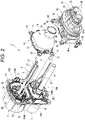
- Fig. 2 is an exploded perspective view showing a main part of the connector 1 shown in Fig. 1 .
- the connector 1 according to the embodiment can be suitably used in a power-reception-side connector to be mounted on a vehicle, which serves as a charging connector.
- the connector may also be used as a power-supply-side connector mounted on a vehicle.
- the connector 1 according to the embodiment is connected to end portions of a plurality of electric wires 5.
- Each of the electric wires 5 to which the connector 1 is connected may be a power line, a ground line, a signal line, or the like.
- a counterpart connector (not shown) is to be connected to a front portion of the connector 1.
- the connector 1 includes a first connector portion 2 and a second connector portion 3.
- Terminals (terminal fittings) 10A are mounted to the first connector portion 2 from a rear side of the first connector portion 2 and terminals (terminal fittings) 10B are mounted to the second connector portion 3 from a rear side of the second connector portion 3.
- Each of the terminals 10A connected to the electric wire 5 provided as, for example, a signal line is inserted and mounted to the first connector portion 2, and each of the terminals 10B connected to the electric wire 5 provided as, for example, a power line is inserted and mounted to the second connector portion 3.
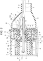
- Fig. 3 is a cross-sectional view showing the first connector portion 2 in the connector 1 shown in Fig. 1 .
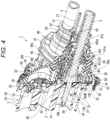
- Fig. 4 is a cross-sectional perspective view showing the second connector portion 3 in the connector 1 shown in Fig. 1 .
- the connector 1 according to the present embodiment mainly includes the terminals 10A, 10B, a front housing 50, a retainer 30, a front holder 40, a first rear housing 60, a first heat retaining cover 70, a second rear housing 80, a second heat retaining cover 90, and temperature sensors 100A, 100B.
- the first connector portion 2 includes the terminals 10A, the front housing 50, the retainer 30, the front holder 40, the first rear housing 60, the first heat retaining cover 70, and the temperature sensors 100A.
- the second connector portion 3 includes the terminals 10B, the front housing 50, the second rear housing 80, the second heat retaining cover 90, and the temperature sensors 100B.
- the terminals 10A, 10B that are terminal fittings according to the present embodiment are formed of a conductive metal material such as copper and a copper alloy, and are manufactured by cutting a round bar formed of the conductive metal material.
- Each of the terminals 10A, 10B is provided with an electrical connection portion 11A, 11B at a front end side of the terminals 10A, 10B, and an electric wire connection portion 12A, 12B at a rear end side of the terminals 10A, 10B.
- Each of the terminals 10A, 10B includes a flange portion 13A, 13B extending to an outer periphery (radially outward) and provided between the electrical connection portion 11A, 11B and the electric wire connection portion 12A, 12B.
- the terminals 10A, 10B are mounted to the front housing 50 of the connector 1 from a rear side of the connector 1 (from a rear side of an insertion direction of the terminals 10A, 10B in which the terminals 10A, 10B are inserted into the front housing 50).
- the temperature sensors 100A, 100B are thermistors each having a thermistor element for detecting a temperature, and are formed into a substantially rectangular parallelepiped shape in which the thermistor element is covered with a resin. Detection lines 27 respectively connected to thermistor elements are drawn out from rear ends of the temperature sensors 100A, 100B.
- Each of the temperature sensors 100A is fixed to an outer surface of the electric wire connection portion 12A of the terminal 10A connected to an end portion of the electric wire 5 by a heat shrinkable tube or the like such that the temperature sensors 100A contact the outer surface of the electric wire connection portion 12A.
- Each of the temperature sensors 100B is fixed by means of, for example, a sensor holder 56 attached to the front housing 50, to an outer surface of a base portion of the electric wire connection portion 12B in the vicinity of (near/ close to) the flange portion 13B of the terminal 10B, which is connected to an end portion of the electric wire 5, such that each of the temperature sensors 100B contacts the outer surface of the base portion of the electric wire connection portion 12B.
- a housing according to the present embodiment includes the front housing 50, the first rear housing 60, and the second rear housing 80.
- Each of the front housing 50, the first rear housing 60, and the second rear housing 80 is formed of a synthetic resin.
- the front housing 50 is formed into a substantially cylindrical shape and include the first connector portion 2 and the second connector portion 3 as partitioned portions.
- the front housing 50 includes partition walls 23 and 33 extending in an up-down direction (in a vertical direction of the front housing 50 or a direction perpendicular to the insertion direction of the terminals 10A, 10B) and provided in a rear side of the front housing 50 in an axial direction.
- the partition walls 23 and 33 partition an inside of the front housing 50 in a front-rear manner, i.e., the partition walls 23 and 33 divide an inner space of the front housing 50 into two, a front space and a rear space.
- a portion further in a front side than the partition wall 23 is a front peripheral wall 24 of the first connector portion 2, and a portion further in a front side than the partition wall 33 is a front peripheral wall 34 of the second connector portion 3.
- a portion further at a rear side than the partition wall 23 is a rear peripheral wall 25 of the first connector portion 2, and a portion further in a rear side than the partition wall 33 is a rear peripheral wall 35 of the second connector portion 3.
- An attachment flange 52 having a bolt hole 51 protrudes toward an outer peripheral side of the front housing 50 (protrudes radially outward).
- a bolt 55 (see Fig. 4 ) inserted into the bolt hole 51 of the attachment flange 52 is to be screwed into a screw hole (not shown) of a vehicle, such that the connector 1 is attached to the vehicle.
- the front holder 40 is attached inside the front peripheral wall 24, and the retainer 30 and the first rear housing 60 are attached in the rear peripheral wall 25.
- the first heat retaining cover 70 is mounted to a rear side of the rear peripheral wall 25.
- a plurality of terminal accommodating chambers 26 are formed in the partition wall 23 of the front housing 50.
- the terminals 10A are inserted into the terminal accommodating chambers 26 from the rear side of the front housing 50.
- the terminal accommodating chamber 26 is formed with a seal hole 17 having a smaller diameter than the terminal accommodating chamber 26, and is further formed with a through hole 28 having a smaller diameter than the seal hole 17.
- the electrical connection portion 11 A is inserted into the through hole 28, and the flange portion 13Ais locked by a bottom portion 26a of the terminal accommodating chamber 26 to restrict a forward movement of the terminal 10A in the insertion direction.
- An annular seal member 15 and an O-ring 14 are mounted to the terminal 10A, which is to be inserted into the terminal accommodating chamber 26, at a base part of the electrical connection portion 11A connected to/ in the vicinity off near/ close to the flange portion 13A. Accordingly, when the terminal 10A is inserted into the terminal accommodating chamber 26, the O-ring 14 is pushed into the seal hole 17 by the seal member 15, and the seal member 15 is interposed between the bottom portion 26a of the terminal accommodating chamber 26 and the flange portion 13A. Accordingly, a space between the terminal accommodating chamber 26 and the terminal 10A inserted into the terminal accommodating chamber 26 is sealed by the O-ring 14.
- the temperature sensor 100A is fixed to the electric wire connection portion 12A of the terminal 10A, and the detection line 27 drawn out from the temperature sensor 100A is routed along the electric wire 5.
- the front housing 50 has a fitting recessed portion 29 inside the front peripheral wall 24.
- the fitting recessed portion 29 is formed further in the front side of the front housing 50 than the partition wall 23.
- the front holder 40 is formed of a synthetic resin and has a plurality of accommodating holes 41.
- a rear portion of the front holder 40 is a fitting portion 42.
- the fitting portion 42 is fitted into the fitting recessed portion 29 of the front housing 50, so that the front holder 40 is attached to the front housing 50 and disposed inside the front peripheral wall 24.
- the accommodating hole 41 communicates with the through hole 28 of the partition wall 23 of the front housing 50. Accordingly, the electrical connection portion 11A of the terminal 10A that has passed through the through hole 28 is accommodated in the accommodating hole 41 of the front holder 40.
- the first rear housing 60 is formed into a plate shape having a plurality of communicating holes 61.
- the communicating holes 61 communicate with the terminal accommodating chambers 26 of the front housing 50 when the first rear housing 60 is attached to the front housing 50.
- the first rear housing 60 has a plurality of lances 62. These lances 62 are formed integrally with respective edges of the communicating holes 61, and extend in a direction in which the first rear housing 60 is attached to the front housing 50.
- a locking claw 63 protruding toward the center of the communicating hole 61 is formed at a tip end portion of each of the lances 62.
- the retainer 30 is formed of a synthetic resin, and is formed into a plate shape.
- the retainer 30 is disposed between the front housing 50 and the first rear housing 60 when the first rear housing 60 is attached to the front housing 50. Accordingly, the retainer 30 is disposed inside the rear peripheral wall 25 of the front housing 50, and is slidably supported with respect to the front housing 50 and the first rear housing 60 in a direction perpendicular to the insertion direction in which the terminal 10A is inserted into the front housing 50.
- the retainer is configured to be displaceable/movable between a locking position and a non-locking position along the direction perpendicular to the insertion direction in which the terminal 10A is inserted into the front housing 50.
- the retainer 30 has a plurality of openings 31.
- the openings 31 are configured to communicate with the terminal accommodating chambers 26 of the front housing 50 and the communicating holes 61 of the first rear housing 60.
- the lances 62 of the first rear housing 60 are configured to be inserted through the openings 31.
- the terminal 10A When the terminal 10A is attached to the front housing 50, in a state where the retainer 30 is in the non-locking position, the terminal 10A is inserted into the communicating hole 61 from a rear side of the first rear housing 60, and the electrical connection portion 11A is inserted into the through hole 28 of the front housing 50 and is accommodated in the terminal accommodating chamber 26. Then, the flange portion 13A of the terminal 10A is locked by the locking claw 63 of the lance 62, a rearward movement in the insertion direction of the terminal 10A is restricted, and the terminal 10A is prevented from coming off.
- each locking portion of the retainer 30 enters a space behind the flange portion 13A of the terminal 10A accommodated in the terminal accommodating chamber 26. Accordingly, the flange portion 13A of the terminal 10A is locked at two positions by the lance 62 of the first rear housing 60 and the locking portion of the retainer 30.
- the first heat retaining cover 70 is mounted to the rear peripheral wall 25 of the front housing 50 so as to cover a rear end portion of the first rear housing 60.
- the first heat retaining cover 70 is formed of a synthetic resin, and is provided as a protector formed into a funnel shape.
- the first heat retaining cover 70 mainly includes an attachment flange 72, an enlarged diameter portion 73, a narrowed portion 74 and an electric wire guiding out portion 75.
- the attachment flange 72 has a bolt hole 71.
- the attachment flange 72 protrudes from the enlarged diameter portion 73 toward an outer peripheral side (protrude radially outward).
- the first heat retaining cover 70 is to be attached to a vehicle at the attachment flange 72 by the bolt 55, together with the attachment flange 52 of the front housing 50.
- the electric wire guiding out portion 75 is provided at a rear end of the narrowed portion 74 extending rearward from the enlarged diameter portion 73 of the first heat retaining cover 70.
- the narrowed portion 74 is disposed between the enlarged diameter portion 73 and the electric wire guiding out portion 75.
- the electric wire guiding out portion 75 is configured such that the electric wire 5 and the detection line 27 that are drawn out from the terminal accommodating chamber 26 are to be passed through the electric wire guiding out portion 75.
- the first heat retaining cover 70 is mounted to cover the rear end portion of the first rear housing 60 having the communicating holes 61 communicating with the terminal accommodating chambers 26, so that heat inside of the terminal accommodating chambers 26 can be retained.
- the first heat retaining cover 70 is attached to the rear peripheral wall 25 of the front housing 50 such that the first heat retaining cover 70 covers/accommodate the rear end portion of the first rear housing 60.
- the electric wire guiding out portion 75 has an opening 76 configured such that the electric wire 5 and the detection line 27 are to be passed therethrough.
- the opening 76 has a minimum size or is covered with an adhesive tape (not shown) so as not to impair a heat retaining property (heat insulation property) in the first heat retaining cover 70.
- an accommodating hole 39 is provided in the front peripheral wall 34, and the second rear housing 80 is attached to an outer side of the rear peripheral wall 35.
- the second heat retaining cover 90 is mounted to a rear side of the second rear housing 80.
- a plurality of terminal accommodating chambers 36 are formed in the partition wall 33 of the front housing 50.
- the terminals 10B are inserted into the terminal accommodating chambers 36 from a rear side of the front housing 50.
- each of the terminal accommodating chambers 36 is formed with a seal hole 37 having a smaller diameter than the terminal accommodating chamber 36, and is further formed with a through hole 38 having a smaller diameter than the seal hole 37.
- the electrical connection portion 11B is inserted into the through hole 38, and the flange portion 13B is locked by a bottom portion 36a of the terminal accommodating chamber 36 to restrict a forward movement of the terminal 10B.
- the annular seal member 15 and the O-ring 14 are mounted to the terminal 10B, which is inserted into the terminal accommodating chamber 36, at a base portion of the electrical connection portion 11B connected/ in the vicinity off near/ close to the flange portion 13B. Accordingly, when the terminal 10B is inserted into the terminal accommodating chamber 36, the O-ring 14 is pushed into the seal hole 37 by the seal member 15, and the seal member 15 is interposed between the bottom portion 36a of the terminal accommodating chamber 36 and the flange portion 13B. Accordingly, a space between the terminal accommodating chamber 36 and the terminal 10B inserted into the terminal accommodating chamber 36 is sealed by the O-ring 14.
- the front housing 50 has the accommodating hole 39 inside the front peripheral wall 24.
- the accommodating hole 39 is formed further in the front side of the front housing 50 than the partition wall 33 and communicates with the through hole 38 of the partition wall 33. Accordingly, the electrical connection portion 11B of the terminal 10B that has passed through the through hole 38 is accommodated in the accommodating hole 39.
- the second rear housing 80 is formed into a cylindrical shape having a plurality of communicating holes 83.
- the communicating holes 83 communicate with the terminal accommodating chambers 36 of the front housing 50 when the second rear housing 80 is attached to the front housing 50.
- the second rear housing 80 includes an electric wire seal accommodating portion 85 and a detection line seal accommodating portion 87 at a rear end of the communicating hole 83.
- An electric wire seal member 101 is mounted to the electric wire seal accommodating portion 85 and is prevented from coming off by a seal holder 103.
- the electric wire seal member 101 is provided with an electric wire seal hole 101a through which the electric wire 5 is inserted.
- the electric wire 5 inserted into the communicating hole 83 of the second rear housing 80 is sealed by the electric wire seal member 101 between the electric wire 5 and the electric wire seal accommodating portion 85 (i.e., the space inside the electric wire seal accommodating portion 85 between an outer surface of the electric wire 5 and a surface defining the electric wire seal accommodating portion 85 is sealed by the electric wire seal member 101).
- a detection line seal member 105 is mounted to the detection line seal accommodating portion 87 provided above the electric wire seal accommodating portion 85.
- the detection line seal member 105 is provided with a detection line seal hole 105a through which the detection line 27 is inserted.
- the detection line 27 drawn out from the communicating hole 83 of the second rear housing 80 is sealed by the detection line seal member 105 between the detection line 27 and the detection line seal accommodating portion 87 (i.e., the space between an outer surface of the detection line 27 and a surface defining the detection line seal accommodating portion 87 is sealed by the detection line seal member 105).
- the second rear housing 80 has a plurality of lances (not shown). These lances are formed integrally with respective edges of the communicating holes 83, and extend in a direction in which the second rear housing 80 is attached to the front housing 50. A locking claw protruding toward the center of the communicating hole 83 is formed at a tip end portion of each of the lances. Therefore, when the electric wire connection portion 12B of the terminal 10B connected to an end portion of the electric wire 5 is inserted into the communicating hole 83 from a front side of the second rear housing 80, the flange portion 13B is locked by locking claws of the lances, so that the terminal 10B is held by the second rear housing 80 and is prevented from coming off from the second rear housing 80.
- the electrical connection portion 11B of the terminal 10B held by the second rear housing 80 is inserted through the through hole 38 from a rear side of the partition wall 33, and is accommodated in the terminal accommodating chamber 36.
- An attachment flange 82 having a bolt hole 81 protrudes toward an outer peripheral side of the second rear housing 80 (protrude radially outward), and is attached to a vehicle by the bolt 55 together with the attachment flange 52 of the front housing 50.
- the second heat retaining cover 90 is mounted to a rear end portion of the second rear housing 80 so as to cover the communicating holes 83.
- the second heat retaining cover 90 is formed of an elastic material such as rubber, and is a so-called grommet formed into a substantially cylindrical shape.
- the second heat retaining cover 90 includes a slit 93 configured to facilitate an insertion work of the electric wire 5 and the detection line 27.
- the slit 93 runs along an axial direction of the second heat retaining cover 90.
- the second heat retaining cover 90 includes an enlarged diameter portion 95 and an electric wire guiding out portion 97.
- the enlarged diameter portion 95 of the second heat retaining cover 90 is fitted onto the rear end portion of the second rear housing 80, and is fixed by, for example, a tightening belt wound around a groove 95a on an outer peripheral surface.
- the electric wire guiding out portion 97 is provided at a rear end of the second heat retaining cover 90 extending rearward from the enlarged diameter portion 95. The electric wire 5 and the detection line 27 that are drawn out from the terminal accommodating chamber 36 are to be inserted through the electric wire guiding out portion 97.
- the electric wire guiding out portion 97 of the second heat retaining cover 90 is formed with an electric wire through hole 91 through which the electric wire 5 is inserted and a detection line through hole 92 through which the detection line 27 is inserted. After the electric wire 5 and the detection line 27 are inserted, the electric wire guiding out portion 97 is fixed to the electric wire 5 by, for example, a tightening belt wound around a groove 97a on outer peripheral surface.
- the second heat retaining cover 90 is mounted to the rear end portion of the second rear housing 80 to cover the rear end portion of the second rear housing 80 including the communicating hole 83 communicating with the terminal accommodating chamber 36, so that heat inside of the terminal accommodating chamber 36 can be retained.
- the slit 93 of the second heat retaining cover 90 is covered with an adhesive tape (not shown) so as not to impair a heat insulation property in the second heat retaining cover 90.
- heat emitted from the heat generation portion of each of the terminals 10A, 10B can be retained inside the first heat retaining cover 70 and the second heat retaining cover 90 and therefore the heat can be efficiently transmitted to other parts of the terminals 10A, 10B than the heat generation portion so that temperature of an entirety of each of the terminals 10A, 10B become uniform.
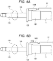
- Figs. 5A and 5B are schematic views showing an attachment state of the temperature sensor 100B attached to the terminal 10B.
- Fig. 5A shows the temperature sensor 100B at a predetermined position and
- Fig. 5B shows the temperature sensor 100B which is displaced from the predetermined position.
- the temperature sensor 100B is fixed on an outer surface of a root of the electric wire connection portion 12B in the vicinity of (near/close to/connected to) the flange portion 13B of the terminal 10B such that the temperature sensor 100B contacts the outer surface of the root of the electric wire connection portion 12B.
- the temperature sensor 100B attached to the terminal 10B may be displaced due to a clearance between components, shrinkage caused by a temperature change, and the like, resulting in the temperature sensor 100B being away from a heat generating portion 110.
- a temperature of the entire terminal 10B is made uniform and temperature detection sensitivity of the temperature sensor 100B is not reduced.
- the temperature sensor 100B in the connector 1 according to the present embodiment can appropriately detect abnormal heat generation. The same applies to the temperature sensor 100A fixed on an outer surface of the electric wire connection portion 12A of the terminal 10A such that the temperature sensor 100A contacts the outer surface of the electric wire connection portion 12A.
- Heat inside of the terminal accommodating chamber 26 and inside of the terminal accommodating chamber 36 is retained by the first heat retaining cover 70 and the second heat retaining cover 90, and heat transfer to the entire terminal 10A and the entire terminal 10B is improved, so that heat can be transferred to the entire terminal 10A, 10B, or the entire housing including the front housing 50, the first rear housing 60, and the second rear housing 80. Therefore, a temperature rise of the terminal 10A, 10B and an increase in electric resistance accompanying with the temperature rise can be prevented, and energization performance can be improved.
- the second connector portion 3 of the connector 1 includes the electric wire seal accommodating portion 85 and the detection line seal accommodating portion 87 that are connected to the terminal accommodating chamber 36, the electric wire seal member 101 that is provided with the electric wire seal hole 101a through which the electric wire 5 is inserted and that is mounted to the electric wire seal accommodating portion 85, and the detection line seal member 105 that is provided with the detection line seal hole 105a through which the detection line 27 is inserted and that is mounted to the detection line seal accommodating portion 87.
- the terminal 10B and the temperature sensor 100B that are accommodated in the terminal accommodating chamber 36 of the second connector portion 3 can be stably waterproof. Further, since the terminal accommodating chamber 36 is sealed by the electric wire seal member 101 and the detection line seal member 105, a heat insulation effect in the terminal accommodating chamber 36 that is achieved by the second heat retaining cover 90 can be further improved, and heat transfer to the entire terminal 10B can be further improved.
- a temperature of the terminal 10A, 10B can be accurately measured without reducing the temperature detection sensitivity of the temperature sensor 100A, 100B.
- the heat retaining cover according to the present invention for heat insulating the inside of the terminal accommodating chamber is not limited to the first heat retaining cover 70 and the second heat retaining cover 90 in the embodiment described above, and can adopt forms of various wire harness exterior materials such as a corrugated tube and a twist tube based on the gist of the present invention.
- a connector (1) includes a terminal fitting (terminal 10A, 10B) connected to an end of an electric wire (5), a housing (front housing 50) including a terminal accommodating chamber (26, 36) configured to accommodate the terminal fitting (terminal 10A, 10B), a temperature sensor (100A, 100B) connected to an end of a detection line (27) and configured to be attached to the terminal fitting (terminal 10A, 10B), and a heat retaining cover (the first heat retaining cover 70, the second heat retaining cover 90).
- the heat retaining cover (the first heat retaining cover 70, the second heat retaining cover 90) is configured to: be attached to the housing (front housing 50) such that the heat retaining cover (the first heat retaining cover 70, the second heat retaining cover 90) covers a rear end portion of the housing (front housing 50); and to retain heat inside the terminal accommodating chamber (26, 36), the heat retaining cover (the first heat retaining cover 70, the second heat retaining cover 90) having an electric wire guiding out portion (75, 97) through which the electric wire (5) and the detection line (27) drawn out from the terminal accommodating chamber (26, 36) are to be inserted.
- the connector having the above described configuration heat inside of the terminal accommodating chamber is retained by the heat retaining cover and heat transfer from a heat generating portion (for example, a portion in contact with a counterpart terminal fitting) of the terminal fitting is improved, so that a temperature of the entire terminal fitting is made uniform or homogenized. Therefore, even when the temperature sensor attached to the terminal fitting is displaced due to a clearance between components, shrinkage caused by a temperature change, and the like, temperature detection sensitivity of the temperature sensor is not reduced. As a result, the temperature sensor in the connector having the configuration can appropriately detect abnormal heat generation. Heat inside of the terminal accommodating chamber is retained by the heat retaining cover and heat transfer to the entire terminal fitting is improved, so that heat can be transferred to the entire terminal fitting or the entire housing. Therefore, a temperature rise of the terminal fitting and an increase in electric resistance accompanying with the temperature rise can be prevented, and energization performance can be improved.
- a heat generating portion for example, a portion in contact with a counterpart terminal fitting
- the connector (1) may further include an electric wire seal accommodating portion (85) and a detection line seal accommodating portion (87) continuously provided with the terminal accommodating chamber (36), respectively, an electric wire seal member (101) including an electric wire seal hole (101a) through which the electric wire (5) is to be inserted and configured to be attached to the electric wire seal accommodating portion (85), and a detection line seal member (105) including a detection line seal hole (105a) through which the detection line (27) is to be inserted and configured to be attached to the detection line seal accommodating portion (87).
- an electric wire seal member (101) including an electric wire seal hole (101a) through which the electric wire (5) is to be inserted and configured to be attached to the electric wire seal accommodating portion (85)
- a detection line seal member (105) including a detection line seal hole (105a) through which the detection line (27) is to be inserted and configured to be attached to the detection line seal accommodating portion (87).
- the terminal fitting and the temperature sensor that are accommodated in the terminal accommodating chamber can be stably waterproof. Further, since the terminal accommodating chamber is sealed by the electric wire seal member and the detection line seal member, a heat insulation effect in the terminal accommodating chamber that is achieved by the second heat retaining cover can be further improved, and heat transfer to the entire terminal fitting can be further increased.
- the heat retaining cover (the first heat retaining cover 70, the second heat retaining cover 90) may be configured to homogenize temperature of an entirety of the terminal fitting (terminal 10A, 10B).
Landscapes
- Engineering & Computer Science (AREA)
- Microelectronics & Electronic Packaging (AREA)
- Connector Housings Or Holding Contact Members (AREA)
- Details Of Connecting Devices For Male And Female Coupling (AREA)
Claims (2)
- Connecteur (1) comprenant :un raccord de borne (10A, 10B) connecté à une extrémité d'un fil électrique (5),un boîtier (50) comprenant une chambre de réception de borne (26, 36) configurée pour recevoir le raccord de borne (10A, 10B),des capteurs de température (100A, 100B) qui sont des thermistances ayant chacune un élément de thermistance pour détecter une température, etun couvercle de retenue de chaleur (70, 90),dans lequel le couvercle de retenue de chaleur (70, 90) est configuré : pour être attaché au boîtier (50) de sorte que le couvercle de retenue de chaleur (70, 90) couvre une partie d'extrémité arrière du boîtier (50) ; et pour retenir la chaleur à l'intérieur de la chambre de réception de borne (26, 36),dans lequel le couvercle de retenue de chaleur (70, 90) a une partie de guidage vers l'extérieur de fil électrique (75, 97) à travers laquelle le fil électrique (5) et une ligne de détection (27) étirés vers l'extérieur depuis la chambre de réception de borne (26, 36) doivent être insérés,les capteurs de température (100A, 100B) sont attachés au raccord de borne respectif (10A, 10B),des lignes de détection (27) connectées respectivement à une extrémité des éléments de thermistance sont étirées vers l'extérieur depuis les extrémités arrière des capteurs de température (100A, 100B) ;caractérisé en ce queun capteur (100A) des capteurs de température (100A, 100B) est fixé à une surface extérieure d'une partie de connexion de fil électrique (12A) du raccord de borne (10A) par un tube thermorétractable de sorte que le capteur de température (100A) entre en contact avec la surface extérieure de la partie de connexion de fil électrique (12A), etl'autre capteur (100B) des capteurs de température (100A, 100B) est fixé, au moyen d'un support de capteur (56) attaché au boîtier (50), à une surface extérieure d'une partie de base d'une partie de connexion de fil électrique (12B) au voisinage d'une partie de bride (13B) du raccord de borne (10B) de sorte que le capteur de température (100B) soit en contact avec la surface extérieure de la partie de base de la partie de connexion de fil électrique (12B).
- Connecteur (1) selon la revendication 1 comprenant en outre :une partie de réception de joint de fil électrique (85) et une partie de réception de joint de ligne de détection (87) pourvues en continu de la chambre de réception de borne (36), respectivement,un élément de joint de fil électrique (101) comprenant un trou de joint de fil électrique (101a) à travers lequel le fil électrique (5) doit être inséré et configuré pour être attaché à la partie de réception de joint de fil électrique (85), etun élément de joint de ligne de détection (105) comprenant un trou de joint de ligne de détection (105a) à travers lequel la ligne de détection (27) doit être insérée et configuré pour être attaché à la partie de réception de joint de ligne de détection (87).
Applications Claiming Priority (1)
| Application Number | Priority Date | Filing Date | Title |
|---|---|---|---|
| JP2020017194A JP7068360B2 (ja) | 2020-02-04 | 2020-02-04 | コネクタ |
Publications (2)
| Publication Number | Publication Date |
|---|---|
| EP3863123A1 EP3863123A1 (fr) | 2021-08-11 |
| EP3863123B1 true EP3863123B1 (fr) | 2023-04-05 |
Family
ID=74550498
Family Applications (1)
| Application Number | Title | Priority Date | Filing Date |
|---|---|---|---|
| EP21154937.3A Active EP3863123B1 (fr) | 2020-02-04 | 2021-02-03 | Connecteur |
Country Status (4)
| Country | Link |
|---|---|
| US (1) | US11462864B2 (fr) |
| EP (1) | EP3863123B1 (fr) |
| JP (1) | JP7068360B2 (fr) |
| CN (1) | CN113285273B (fr) |
Families Citing this family (9)
| Publication number | Priority date | Publication date | Assignee | Title |
|---|---|---|---|---|
| DE102020201240A1 (de) * | 2020-01-31 | 2021-08-05 | Te Connectivity Germany Gmbh | Steckverbinderelement und Steckverbinder für Hochvoltanwendungen |
| DE102020116904A1 (de) * | 2020-06-26 | 2021-12-30 | Te Connectivity Germany Gmbh | Hochstromkontakteinrichtung und Verbindungsvorrichtung zur Stromübertragung von elektrischer Energie in einem Kraftfahrzeug |
| EP4106114A1 (fr) * | 2021-06-14 | 2022-12-21 | Vitesco Technologies GmbH | Boîtier de capteur à haute température avec connecteurs de thermocouple et son procédé de fabrication |
| ES3059565T3 (en) * | 2021-10-29 | 2026-03-23 | Contemporary Amperex Technology Hong Kong Ltd | Connector and electric device |
| JP7632347B2 (ja) * | 2022-03-01 | 2025-02-19 | 住友電装株式会社 | 電線付きコネクタ |
| CN116799570A (zh) | 2022-03-11 | 2023-09-22 | 豪利士电线装配(苏州)有限公司 | 具有密封件的电动车辆充电插头 |
| JP2023146265A (ja) * | 2022-03-29 | 2023-10-12 | 住友電装株式会社 | 充電コネクタ |
| CN218940166U (zh) * | 2022-08-11 | 2023-04-28 | 泰科电子(上海)有限公司 | 连接器和连接器组件 |
| IT202200017901A1 (it) * | 2022-08-31 | 2024-03-02 | Clay Paky Spa | Dispositivo di protezione per connessioni elettriche e relativo procedimento |
Citations (2)
| Publication number | Priority date | Publication date | Assignee | Title |
|---|---|---|---|---|
| DE102015004313A1 (de) * | 2015-04-01 | 2016-10-06 | Müller Plastik GmbH | Stecker, insbesondere mit einem Fahrzeugladekabel eines Elektro- oder Hybridfahrzeuges |
| WO2017137826A1 (fr) * | 2016-02-11 | 2017-08-17 | Sumitomo Wiring Systems, Ltd. | Connecteur de charge, armature de borne et procédé de fixation d'un capteur à une armature de borne |
Family Cites Families (24)
| Publication number | Priority date | Publication date | Assignee | Title |
|---|---|---|---|---|
| JP3135040B2 (ja) | 1995-11-30 | 2001-02-13 | 矢崎総業株式会社 | 電気自動車の充電用コネクタ |
| US6208233B1 (en) * | 2000-03-03 | 2001-03-27 | Delphi Technologies, Inc. | Trim resistor connector and sensor system |
| JP2002352635A (ja) | 2001-05-24 | 2002-12-06 | Hitachi Information Technology Co Ltd | 温度センサ付き電源コード |
| JP5984091B2 (ja) * | 2012-09-11 | 2016-09-06 | パナソニックIpマネジメント株式会社 | 電源コード |
| CN105144498B (zh) * | 2013-03-19 | 2017-10-13 | 住友电装株式会社 | 车辆侧连接器 |
| JP6130244B2 (ja) | 2013-06-27 | 2017-05-17 | 矢崎総業株式会社 | 端子及び充電コネクタ |
| US9681571B2 (en) * | 2014-02-21 | 2017-06-13 | Wells Manufacturing, L.P. | Electrical connection box and apparatus |
| JP2016213118A (ja) * | 2015-05-12 | 2016-12-15 | パナソニックIpマネジメント株式会社 | プラグ |
| FR3051903B1 (fr) * | 2016-05-25 | 2020-02-14 | Aptiv Technologies Limited | Attache de cable, ensemble de connexion et procede de mesure de temperature de cable |
| DE102016211876A1 (de) | 2016-06-30 | 2018-01-04 | Phoenix Contact E-Mobility Gmbh | Elektroanschlusseinrichtung mit verbesserter thermischer Kopplung einer einen Temperatursensor aufweisenden Platine |
| JP6467383B2 (ja) | 2016-08-10 | 2019-02-13 | 矢崎総業株式会社 | コネクタ |
| CN206195010U (zh) * | 2016-11-01 | 2017-05-24 | 深圳龙友科技股份有限公司 | 耐高压大电流连接器 |
| JP6571700B2 (ja) * | 2017-02-01 | 2019-09-04 | 矢崎総業株式会社 | コネクタ |
| CN207165796U (zh) * | 2017-05-12 | 2018-03-30 | 泰科电子(上海)有限公司 | 电气防护盖及插座 |
| DE202017106035U1 (de) * | 2017-10-04 | 2019-01-10 | Tmc Sensortechnik Gmbh | Elektrischer Netzstecker |
| DE102017125265B4 (de) * | 2017-10-27 | 2025-10-02 | Phoenix Contact E-Mobility Gmbh | Ladestecker und Ladestation für ein Kraftfahrzeug |
| JP2019192482A (ja) * | 2018-04-25 | 2019-10-31 | 矢崎総業株式会社 | 充電コネクタ |
| JP2019197641A (ja) * | 2018-05-09 | 2019-11-14 | トヨタ自動車株式会社 | コネクタ |
| CN208171458U (zh) * | 2018-05-31 | 2018-11-30 | 泰科电子(上海)有限公司 | 温度传感器导热组件及连接器 |
| CN108847546A (zh) * | 2018-08-01 | 2018-11-20 | 余姚市嘉荣电子电器有限公司 | 一种带热敏电阻的安全插头 |
| US10833458B2 (en) * | 2018-08-21 | 2020-11-10 | Te Connectivity Corporation | Temperature sensor assembly for an electrical connector |
| CN209358010U (zh) * | 2018-12-26 | 2019-09-06 | 深圳市铭泽智能电力科技有限公司 | 一种智能电缆插头 |
| CN209266743U (zh) * | 2019-02-26 | 2019-08-16 | 无锡卡斯迪尔科技有限公司 | 一种带有温度传感器的汽车连接器插座 |
| US11846475B2 (en) * | 2019-08-26 | 2023-12-19 | Te Connectivity Solutions Gmbh | Heat exchanger for a power connector |
-
2020
- 2020-02-04 JP JP2020017194A patent/JP7068360B2/ja active Active
-
2021
- 2021-02-02 CN CN202110144241.3A patent/CN113285273B/zh active Active
- 2021-02-03 EP EP21154937.3A patent/EP3863123B1/fr active Active
- 2021-02-04 US US17/167,104 patent/US11462864B2/en active Active
Patent Citations (2)
| Publication number | Priority date | Publication date | Assignee | Title |
|---|---|---|---|---|
| DE102015004313A1 (de) * | 2015-04-01 | 2016-10-06 | Müller Plastik GmbH | Stecker, insbesondere mit einem Fahrzeugladekabel eines Elektro- oder Hybridfahrzeuges |
| WO2017137826A1 (fr) * | 2016-02-11 | 2017-08-17 | Sumitomo Wiring Systems, Ltd. | Connecteur de charge, armature de borne et procédé de fixation d'un capteur à une armature de borne |
Also Published As
| Publication number | Publication date |
|---|---|
| CN113285273A (zh) | 2021-08-20 |
| US20210242638A1 (en) | 2021-08-05 |
| EP3863123A1 (fr) | 2021-08-11 |
| US11462864B2 (en) | 2022-10-04 |
| CN113285273B (zh) | 2023-08-08 |
| JP7068360B2 (ja) | 2022-05-16 |
| JP2021125341A (ja) | 2021-08-30 |
Similar Documents
| Publication | Publication Date | Title |
|---|---|---|
| EP3863123B1 (fr) | Connecteur | |
| US10063008B2 (en) | Connector | |
| EP3560750A1 (fr) | Connecteur de chargeur | |
| US8167653B2 (en) | Shield shell | |
| KR102231028B1 (ko) | 지지 요소에 수용된 온도 센서를 포함하는 전기장치 | |
| US11462863B2 (en) | Plug-in connector element and plug-in connector for high-voltage applications | |
| EP2466297B1 (fr) | Capteur | |
| CN104716519B (zh) | 电源线 | |
| JP2019521486A (ja) | 温度センサを有するプリント基板への熱的結合を用いる電気的接続装置 | |
| US20240372304A1 (en) | Connector | |
| JP2018156896A (ja) | 端子及びコネクタ | |
| US20240208342A1 (en) | Plug connector part for a charging system for charging an electric vehicle | |
| US11336046B2 (en) | Charging connector | |
| KR20140053792A (ko) | 자동차 분야에서 고압 전류를 전송하기 위한 연결 장치 | |
| US20250202170A1 (en) | Charging inlet | |
| US20240181909A1 (en) | Automotive charging assembly | |
| EP3846294B1 (fr) | Ensemble de terminal pour un connecteur de charge comprenant une surveillance thermique améliorée | |
| US20250058663A1 (en) | Temperature sensor for charging inlet assembly of a vehicle | |
| CN216424104U (zh) | 用于充电插接连接部的接触组件、充电装置和机动车 | |
| CN113532668B (zh) | 保护器及保护器模块 | |
| JP7252772B2 (ja) | サービスプラグ | |
| CN222422483U (zh) | 一种电连接组件 | |
| US12548923B2 (en) | Terminal connection structure | |
| US10124749B2 (en) | Electrical cable and connector with internal temperature-sensing mechanism | |
| JP2025176903A (ja) | センサ搭載構造 |
Legal Events
| Date | Code | Title | Description |
|---|---|---|---|
| PUAI | Public reference made under article 153(3) epc to a published international application that has entered the european phase |
Free format text: ORIGINAL CODE: 0009012 |
|
| STAA | Information on the status of an ep patent application or granted ep patent |
Free format text: STATUS: REQUEST FOR EXAMINATION WAS MADE |
|
| 17P | Request for examination filed |
Effective date: 20210203 |
|
| AK | Designated contracting states |
Kind code of ref document: A1 Designated state(s): AL AT BE BG CH CY CZ DE DK EE ES FI FR GB GR HR HU IE IS IT LI LT LU LV MC MK MT NL NO PL PT RO RS SE SI SK SM TR |
|
| STAA | Information on the status of an ep patent application or granted ep patent |
Free format text: STATUS: EXAMINATION IS IN PROGRESS |
|
| 17Q | First examination report despatched |
Effective date: 20211027 |
|
| GRAP | Despatch of communication of intention to grant a patent |
Free format text: ORIGINAL CODE: EPIDOSNIGR1 |
|
| STAA | Information on the status of an ep patent application or granted ep patent |
Free format text: STATUS: GRANT OF PATENT IS INTENDED |
|
| RIC1 | Information provided on ipc code assigned before grant |
Ipc: H01R 13/66 20060101ALN20220817BHEP Ipc: H01R 13/52 20060101ALI20220817BHEP Ipc: H01R 13/512 20060101AFI20220817BHEP |
|
| RIC1 | Information provided on ipc code assigned before grant |
Ipc: H01R 24/28 20110101ALN20220905BHEP Ipc: H01R 13/66 20060101ALN20220905BHEP Ipc: H01R 13/447 20060101ALI20220905BHEP Ipc: H01R 13/52 20060101ALI20220905BHEP Ipc: H01R 13/512 20060101AFI20220905BHEP |
|
| INTG | Intention to grant announced |
Effective date: 20220919 |
|
| RIN1 | Information on inventor provided before grant (corrected) |
Inventor name: TSUSHIMA, YOSHITAKA Inventor name: SAWADA, TSUTOMU Inventor name: SAITO, AKIHIRO |
|
| GRAJ | Information related to disapproval of communication of intention to grant by the applicant or resumption of examination proceedings by the epo deleted |
Free format text: ORIGINAL CODE: EPIDOSDIGR1 |
|
| STAA | Information on the status of an ep patent application or granted ep patent |
Free format text: STATUS: EXAMINATION IS IN PROGRESS |
|
| GRAP | Despatch of communication of intention to grant a patent |
Free format text: ORIGINAL CODE: EPIDOSNIGR1 |
|
| STAA | Information on the status of an ep patent application or granted ep patent |
Free format text: STATUS: GRANT OF PATENT IS INTENDED |
|
| INTC | Intention to grant announced (deleted) | ||
| RIC1 | Information provided on ipc code assigned before grant |
Ipc: H01R 24/28 20110101ALN20221103BHEP Ipc: H01R 13/66 20060101ALN20221103BHEP Ipc: H01R 13/447 20060101ALI20221103BHEP Ipc: H01R 13/52 20060101ALI20221103BHEP Ipc: H01R 13/512 20060101AFI20221103BHEP |
|
| INTG | Intention to grant announced |
Effective date: 20221118 |
|
| RIC1 | Information provided on ipc code assigned before grant |
Ipc: H01R 24/28 20110101ALN20221108BHEP Ipc: H01R 13/66 20060101ALN20221108BHEP Ipc: H01R 13/447 20060101ALI20221108BHEP Ipc: H01R 13/52 20060101ALI20221108BHEP Ipc: H01R 13/512 20060101AFI20221108BHEP |
|
| GRAS | Grant fee paid |
Free format text: ORIGINAL CODE: EPIDOSNIGR3 |
|
| GRAA | (expected) grant |
Free format text: ORIGINAL CODE: 0009210 |
|
| STAA | Information on the status of an ep patent application or granted ep patent |
Free format text: STATUS: THE PATENT HAS BEEN GRANTED |
|
| AK | Designated contracting states |
Kind code of ref document: B1 Designated state(s): AL AT BE BG CH CY CZ DE DK EE ES FI FR GB GR HR HU IE IS IT LI LT LU LV MC MK MT NL NO PL PT RO RS SE SI SK SM TR |
|
| REG | Reference to a national code |
Ref country code: GB Ref legal event code: FG4D |
|
| REG | Reference to a national code |
Ref country code: CH Ref legal event code: EP |
|
| REG | Reference to a national code |
Ref country code: AT Ref legal event code: REF Ref document number: 1558967 Country of ref document: AT Kind code of ref document: T Effective date: 20230415 |
|
| REG | Reference to a national code |
Ref country code: DE Ref legal event code: R096 Ref document number: 602021001776 Country of ref document: DE |
|
| REG | Reference to a national code |
Ref country code: IE Ref legal event code: FG4D |
|
| RAP4 | Party data changed (patent owner data changed or rights of a patent transferred) |
Owner name: YAZAKI CORPORATION |
|
| REG | Reference to a national code |
Ref country code: LT Ref legal event code: MG9D |
|
| REG | Reference to a national code |
Ref country code: NL Ref legal event code: MP Effective date: 20230405 |
|
| REG | Reference to a national code |
Ref country code: AT Ref legal event code: MK05 Ref document number: 1558967 Country of ref document: AT Kind code of ref document: T Effective date: 20230405 |
|
| PG25 | Lapsed in a contracting state [announced via postgrant information from national office to epo] |
Ref country code: NL Free format text: LAPSE BECAUSE OF FAILURE TO SUBMIT A TRANSLATION OF THE DESCRIPTION OR TO PAY THE FEE WITHIN THE PRESCRIBED TIME-LIMIT Effective date: 20230405 |
|
| PG25 | Lapsed in a contracting state [announced via postgrant information from national office to epo] |
Ref country code: SE Free format text: LAPSE BECAUSE OF FAILURE TO SUBMIT A TRANSLATION OF THE DESCRIPTION OR TO PAY THE FEE WITHIN THE PRESCRIBED TIME-LIMIT Effective date: 20230405 Ref country code: PT Free format text: LAPSE BECAUSE OF FAILURE TO SUBMIT A TRANSLATION OF THE DESCRIPTION OR TO PAY THE FEE WITHIN THE PRESCRIBED TIME-LIMIT Effective date: 20230807 Ref country code: NO Free format text: LAPSE BECAUSE OF FAILURE TO SUBMIT A TRANSLATION OF THE DESCRIPTION OR TO PAY THE FEE WITHIN THE PRESCRIBED TIME-LIMIT Effective date: 20230705 Ref country code: ES Free format text: LAPSE BECAUSE OF FAILURE TO SUBMIT A TRANSLATION OF THE DESCRIPTION OR TO PAY THE FEE WITHIN THE PRESCRIBED TIME-LIMIT Effective date: 20230405 Ref country code: AT Free format text: LAPSE BECAUSE OF FAILURE TO SUBMIT A TRANSLATION OF THE DESCRIPTION OR TO PAY THE FEE WITHIN THE PRESCRIBED TIME-LIMIT Effective date: 20230405 |
|
| PG25 | Lapsed in a contracting state [announced via postgrant information from national office to epo] |
Ref country code: RS Free format text: LAPSE BECAUSE OF FAILURE TO SUBMIT A TRANSLATION OF THE DESCRIPTION OR TO PAY THE FEE WITHIN THE PRESCRIBED TIME-LIMIT Effective date: 20230405 Ref country code: PL Free format text: LAPSE BECAUSE OF FAILURE TO SUBMIT A TRANSLATION OF THE DESCRIPTION OR TO PAY THE FEE WITHIN THE PRESCRIBED TIME-LIMIT Effective date: 20230405 Ref country code: LV Free format text: LAPSE BECAUSE OF FAILURE TO SUBMIT A TRANSLATION OF THE DESCRIPTION OR TO PAY THE FEE WITHIN THE PRESCRIBED TIME-LIMIT Effective date: 20230405 Ref country code: LT Free format text: LAPSE BECAUSE OF FAILURE TO SUBMIT A TRANSLATION OF THE DESCRIPTION OR TO PAY THE FEE WITHIN THE PRESCRIBED TIME-LIMIT Effective date: 20230405 Ref country code: IS Free format text: LAPSE BECAUSE OF FAILURE TO SUBMIT A TRANSLATION OF THE DESCRIPTION OR TO PAY THE FEE WITHIN THE PRESCRIBED TIME-LIMIT Effective date: 20230805 Ref country code: HR Free format text: LAPSE BECAUSE OF FAILURE TO SUBMIT A TRANSLATION OF THE DESCRIPTION OR TO PAY THE FEE WITHIN THE PRESCRIBED TIME-LIMIT Effective date: 20230405 Ref country code: GR Free format text: LAPSE BECAUSE OF FAILURE TO SUBMIT A TRANSLATION OF THE DESCRIPTION OR TO PAY THE FEE WITHIN THE PRESCRIBED TIME-LIMIT Effective date: 20230706 Ref country code: AL Free format text: LAPSE BECAUSE OF FAILURE TO SUBMIT A TRANSLATION OF THE DESCRIPTION OR TO PAY THE FEE WITHIN THE PRESCRIBED TIME-LIMIT Effective date: 20230405 |
|
| PG25 | Lapsed in a contracting state [announced via postgrant information from national office to epo] |
Ref country code: FI Free format text: LAPSE BECAUSE OF FAILURE TO SUBMIT A TRANSLATION OF THE DESCRIPTION OR TO PAY THE FEE WITHIN THE PRESCRIBED TIME-LIMIT Effective date: 20230405 |
|
| REG | Reference to a national code |
Ref country code: DE Ref legal event code: R097 Ref document number: 602021001776 Country of ref document: DE |
|
| PG25 | Lapsed in a contracting state [announced via postgrant information from national office to epo] |
Ref country code: SK Free format text: LAPSE BECAUSE OF FAILURE TO SUBMIT A TRANSLATION OF THE DESCRIPTION OR TO PAY THE FEE WITHIN THE PRESCRIBED TIME-LIMIT Effective date: 20230405 |
|
| PG25 | Lapsed in a contracting state [announced via postgrant information from national office to epo] |
Ref country code: SM Free format text: LAPSE BECAUSE OF FAILURE TO SUBMIT A TRANSLATION OF THE DESCRIPTION OR TO PAY THE FEE WITHIN THE PRESCRIBED TIME-LIMIT Effective date: 20230405 Ref country code: SK Free format text: LAPSE BECAUSE OF FAILURE TO SUBMIT A TRANSLATION OF THE DESCRIPTION OR TO PAY THE FEE WITHIN THE PRESCRIBED TIME-LIMIT Effective date: 20230405 Ref country code: RO Free format text: LAPSE BECAUSE OF FAILURE TO SUBMIT A TRANSLATION OF THE DESCRIPTION OR TO PAY THE FEE WITHIN THE PRESCRIBED TIME-LIMIT Effective date: 20230405 Ref country code: EE Free format text: LAPSE BECAUSE OF FAILURE TO SUBMIT A TRANSLATION OF THE DESCRIPTION OR TO PAY THE FEE WITHIN THE PRESCRIBED TIME-LIMIT Effective date: 20230405 Ref country code: DK Free format text: LAPSE BECAUSE OF FAILURE TO SUBMIT A TRANSLATION OF THE DESCRIPTION OR TO PAY THE FEE WITHIN THE PRESCRIBED TIME-LIMIT Effective date: 20230405 Ref country code: CZ Free format text: LAPSE BECAUSE OF FAILURE TO SUBMIT A TRANSLATION OF THE DESCRIPTION OR TO PAY THE FEE WITHIN THE PRESCRIBED TIME-LIMIT Effective date: 20230405 |
|
| PLBE | No opposition filed within time limit |
Free format text: ORIGINAL CODE: 0009261 |
|
| STAA | Information on the status of an ep patent application or granted ep patent |
Free format text: STATUS: NO OPPOSITION FILED WITHIN TIME LIMIT |
|
| 26N | No opposition filed |
Effective date: 20240108 |
|
| PG25 | Lapsed in a contracting state [announced via postgrant information from national office to epo] |
Ref country code: SI Free format text: LAPSE BECAUSE OF FAILURE TO SUBMIT A TRANSLATION OF THE DESCRIPTION OR TO PAY THE FEE WITHIN THE PRESCRIBED TIME-LIMIT Effective date: 20230405 |
|
| PG25 | Lapsed in a contracting state [announced via postgrant information from national office to epo] |
Ref country code: SI Free format text: LAPSE BECAUSE OF FAILURE TO SUBMIT A TRANSLATION OF THE DESCRIPTION OR TO PAY THE FEE WITHIN THE PRESCRIBED TIME-LIMIT Effective date: 20230405 Ref country code: IT Free format text: LAPSE BECAUSE OF FAILURE TO SUBMIT A TRANSLATION OF THE DESCRIPTION OR TO PAY THE FEE WITHIN THE PRESCRIBED TIME-LIMIT Effective date: 20230405 |
|
| PG25 | Lapsed in a contracting state [announced via postgrant information from national office to epo] |
Ref country code: MC Free format text: LAPSE BECAUSE OF FAILURE TO SUBMIT A TRANSLATION OF THE DESCRIPTION OR TO PAY THE FEE WITHIN THE PRESCRIBED TIME-LIMIT Effective date: 20230405 |
|
| REG | Reference to a national code |
Ref country code: CH Ref legal event code: PL |
|
| PG25 | Lapsed in a contracting state [announced via postgrant information from national office to epo] |
Ref country code: LU Free format text: LAPSE BECAUSE OF NON-PAYMENT OF DUE FEES Effective date: 20240203 |
|
| PG25 | Lapsed in a contracting state [announced via postgrant information from national office to epo] |
Ref country code: CH Free format text: LAPSE BECAUSE OF NON-PAYMENT OF DUE FEES Effective date: 20240229 |
|
| PG25 | Lapsed in a contracting state [announced via postgrant information from national office to epo] |
Ref country code: LU Free format text: LAPSE BECAUSE OF NON-PAYMENT OF DUE FEES Effective date: 20240203 Ref country code: CH Free format text: LAPSE BECAUSE OF NON-PAYMENT OF DUE FEES Effective date: 20240229 |
|
| PG25 | Lapsed in a contracting state [announced via postgrant information from national office to epo] |
Ref country code: BG Free format text: LAPSE BECAUSE OF FAILURE TO SUBMIT A TRANSLATION OF THE DESCRIPTION OR TO PAY THE FEE WITHIN THE PRESCRIBED TIME-LIMIT Effective date: 20230405 |
|
| PG25 | Lapsed in a contracting state [announced via postgrant information from national office to epo] |
Ref country code: BG Free format text: LAPSE BECAUSE OF FAILURE TO SUBMIT A TRANSLATION OF THE DESCRIPTION OR TO PAY THE FEE WITHIN THE PRESCRIBED TIME-LIMIT Effective date: 20230405 |
|
| REG | Reference to a national code |
Ref country code: BE Ref legal event code: MM Effective date: 20240229 |
|
| PG25 | Lapsed in a contracting state [announced via postgrant information from national office to epo] |
Ref country code: BE Free format text: LAPSE BECAUSE OF NON-PAYMENT OF DUE FEES Effective date: 20240229 |
|
| PG25 | Lapsed in a contracting state [announced via postgrant information from national office to epo] |
Ref country code: FR Free format text: LAPSE BECAUSE OF NON-PAYMENT OF DUE FEES Effective date: 20240229 |
|
| PG25 | Lapsed in a contracting state [announced via postgrant information from national office to epo] |
Ref country code: IE Free format text: LAPSE BECAUSE OF NON-PAYMENT OF DUE FEES Effective date: 20240203 |
|
| PG25 | Lapsed in a contracting state [announced via postgrant information from national office to epo] |
Ref country code: IE Free format text: LAPSE BECAUSE OF NON-PAYMENT OF DUE FEES Effective date: 20240203 Ref country code: FR Free format text: LAPSE BECAUSE OF NON-PAYMENT OF DUE FEES Effective date: 20240229 Ref country code: BE Free format text: LAPSE BECAUSE OF NON-PAYMENT OF DUE FEES Effective date: 20240229 |
|
| PG25 | Lapsed in a contracting state [announced via postgrant information from national office to epo] |
Ref country code: CY Free format text: LAPSE BECAUSE OF FAILURE TO SUBMIT A TRANSLATION OF THE DESCRIPTION OR TO PAY THE FEE WITHIN THE PRESCRIBED TIME-LIMIT; INVALID AB INITIO Effective date: 20210203 |
|
| PG25 | Lapsed in a contracting state [announced via postgrant information from national office to epo] |
Ref country code: HU Free format text: LAPSE BECAUSE OF FAILURE TO SUBMIT A TRANSLATION OF THE DESCRIPTION OR TO PAY THE FEE WITHIN THE PRESCRIBED TIME-LIMIT; INVALID AB INITIO Effective date: 20210203 |
|
| GBPC | Gb: european patent ceased through non-payment of renewal fee |
Effective date: 20250203 |
|
| PG25 | Lapsed in a contracting state [announced via postgrant information from national office to epo] |
Ref country code: TR Free format text: LAPSE BECAUSE OF FAILURE TO SUBMIT A TRANSLATION OF THE DESCRIPTION OR TO PAY THE FEE WITHIN THE PRESCRIBED TIME-LIMIT Effective date: 20230405 |
|
| PG25 | Lapsed in a contracting state [announced via postgrant information from national office to epo] |
Ref country code: GB Free format text: LAPSE BECAUSE OF NON-PAYMENT OF DUE FEES Effective date: 20250203 |
|
| PGFP | Annual fee paid to national office [announced via postgrant information from national office to epo] |
Ref country code: DE Payment date: 20251230 Year of fee payment: 6 |