EP3864246B1 - Dispositif de ralentissement présentant un élément d'entraînement en plusieurs parties - Google Patents
Dispositif de ralentissement présentant un élément d'entraînement en plusieurs parties Download PDFInfo
- Publication number
- EP3864246B1 EP3864246B1 EP19809376.7A EP19809376A EP3864246B1 EP 3864246 B1 EP3864246 B1 EP 3864246B1 EP 19809376 A EP19809376 A EP 19809376A EP 3864246 B1 EP3864246 B1 EP 3864246B1
- Authority
- EP
- European Patent Office
- Prior art keywords
- pin
- housing
- guide
- cylinder
- slide
- Prior art date
- Legal status (The legal status is an assumption and is not a legal conclusion. Google has not performed a legal analysis and makes no representation as to the accuracy of the status listed.)
- Active
Links
Images




Classifications
-
- E—FIXED CONSTRUCTIONS
- E05—LOCKS; KEYS; WINDOW OR DOOR FITTINGS; SAFES
- E05F—DEVICES FOR MOVING WINGS INTO OPEN OR CLOSED POSITION; CHECKS FOR WINGS; WING FITTINGS NOT OTHERWISE PROVIDED FOR, CONCERNED WITH THE FUNCTIONING OF THE WING
- E05F1/00—Closers or openers for wings, not otherwise provided for in this subclass
- E05F1/08—Closers or openers for wings, not otherwise provided for in this subclass spring-actuated, e.g. for horizontally sliding wings
- E05F1/16—Closers or openers for wings, not otherwise provided for in this subclass spring-actuated, e.g. for horizontally sliding wings for sliding wings
-
- E—FIXED CONSTRUCTIONS
- E05—LOCKS; KEYS; WINDOW OR DOOR FITTINGS; SAFES
- E05F—DEVICES FOR MOVING WINGS INTO OPEN OR CLOSED POSITION; CHECKS FOR WINGS; WING FITTINGS NOT OTHERWISE PROVIDED FOR, CONCERNED WITH THE FUNCTIONING OF THE WING
- E05F5/00—Braking devices, e.g. checks; Stops; Buffers
- E05F5/003—Braking devices, e.g. checks; Stops; Buffers for sliding wings
-
- E—FIXED CONSTRUCTIONS
- E05—LOCKS; KEYS; WINDOW OR DOOR FITTINGS; SAFES
- E05Y—INDEXING SCHEME ASSOCIATED WITH SUBCLASSES E05D AND E05F, RELATING TO CONSTRUCTION ELEMENTS, ELECTRIC CONTROL, POWER SUPPLY, POWER SIGNAL OR TRANSMISSION, USER INTERFACES, MOUNTING OR COUPLING, DETAILS, ACCESSORIES, AUXILIARY OPERATIONS NOT OTHERWISE PROVIDED FOR, APPLICATION THEREOF
- E05Y2201/00—Constructional elements; Accessories therefor
- E05Y2201/40—Motors; Magnets; Springs; Weights; Accessories therefor
- E05Y2201/404—Function thereof
- E05Y2201/41—Function thereof for closing
- E05Y2201/412—Function thereof for closing for the final closing movement
-
- E—FIXED CONSTRUCTIONS
- E05—LOCKS; KEYS; WINDOW OR DOOR FITTINGS; SAFES
- E05Y—INDEXING SCHEME ASSOCIATED WITH SUBCLASSES E05D AND E05F, RELATING TO CONSTRUCTION ELEMENTS, ELECTRIC CONTROL, POWER SUPPLY, POWER SIGNAL OR TRANSMISSION, USER INTERFACES, MOUNTING OR COUPLING, DETAILS, ACCESSORIES, AUXILIARY OPERATIONS NOT OTHERWISE PROVIDED FOR, APPLICATION THEREOF
- E05Y2800/00—Details, accessories and auxiliary operations not otherwise provided for
- E05Y2800/20—Combinations of elements
- E05Y2800/205—Combinations of elements forming a unit
-
- E—FIXED CONSTRUCTIONS
- E05—LOCKS; KEYS; WINDOW OR DOOR FITTINGS; SAFES
- E05Y—INDEXING SCHEME ASSOCIATED WITH SUBCLASSES E05D AND E05F, RELATING TO CONSTRUCTION ELEMENTS, ELECTRIC CONTROL, POWER SUPPLY, POWER SIGNAL OR TRANSMISSION, USER INTERFACES, MOUNTING OR COUPLING, DETAILS, ACCESSORIES, AUXILIARY OPERATIONS NOT OTHERWISE PROVIDED FOR, APPLICATION THEREOF
- E05Y2800/00—Details, accessories and auxiliary operations not otherwise provided for
- E05Y2800/20—Combinations of elements
- E05Y2800/23—Combinations of elements of elements of different categories
- E05Y2800/24—Combinations of elements of elements of different categories of springs and brakes
-
- E—FIXED CONSTRUCTIONS
- E05—LOCKS; KEYS; WINDOW OR DOOR FITTINGS; SAFES
- E05Y—INDEXING SCHEME ASSOCIATED WITH SUBCLASSES E05D AND E05F, RELATING TO CONSTRUCTION ELEMENTS, ELECTRIC CONTROL, POWER SUPPLY, POWER SIGNAL OR TRANSMISSION, USER INTERFACES, MOUNTING OR COUPLING, DETAILS, ACCESSORIES, AUXILIARY OPERATIONS NOT OTHERWISE PROVIDED FOR, APPLICATION THEREOF
- E05Y2800/00—Details, accessories and auxiliary operations not otherwise provided for
- E05Y2800/40—Physical or chemical protection
- E05Y2800/422—Physical or chemical protection against vibration or noise
-
- E—FIXED CONSTRUCTIONS
- E05—LOCKS; KEYS; WINDOW OR DOOR FITTINGS; SAFES
- E05Y—INDEXING SCHEME ASSOCIATED WITH SUBCLASSES E05D AND E05F, RELATING TO CONSTRUCTION ELEMENTS, ELECTRIC CONTROL, POWER SUPPLY, POWER SIGNAL OR TRANSMISSION, USER INTERFACES, MOUNTING OR COUPLING, DETAILS, ACCESSORIES, AUXILIARY OPERATIONS NOT OTHERWISE PROVIDED FOR, APPLICATION THEREOF
- E05Y2900/00—Application of doors, windows, wings or fittings thereof
- E05Y2900/10—Application of doors, windows, wings or fittings thereof for buildings or parts thereof
- E05Y2900/13—Type of wing
- E05Y2900/132—Doors
-
- E—FIXED CONSTRUCTIONS
- E05—LOCKS; KEYS; WINDOW OR DOOR FITTINGS; SAFES
- E05Y—INDEXING SCHEME ASSOCIATED WITH SUBCLASSES E05D AND E05F, RELATING TO CONSTRUCTION ELEMENTS, ELECTRIC CONTROL, POWER SUPPLY, POWER SIGNAL OR TRANSMISSION, USER INTERFACES, MOUNTING OR COUPLING, DETAILS, ACCESSORIES, AUXILIARY OPERATIONS NOT OTHERWISE PROVIDED FOR, APPLICATION THEREOF
- E05Y2900/00—Application of doors, windows, wings or fittings thereof
- E05Y2900/20—Application of doors, windows, wings or fittings thereof for furniture, e.g. cabinets
Definitions
- the invention relates to a deceleration device with a housing, with a cylinder-piston unit mounted in the housing, having a cylinder and a piston, and with a driving element mounted in the housing so as to be displaceable between a non-positively and/or positively secured parking position and an end position and back, wherein the driving element loads the piston relative to the cylinder at least when moving in the direction of the end position, and wherein the driving element comprises a carriage with a first sliding and pivot pin and a pull pin pivotably mounted thereon in a pivot joint with a second sliding and pivot pin, wherein the sliding and pivot pins are inserted in a first guide track oriented in a longitudinal direction of the deceleration device and wherein the pull pin is rigidly connected to at least one guide pin guided in the housing and movable parallel to the carriage at least in a stroke section adjacent to the end position, as well as a combined acceleration and deceleration device with such a deceleration device and with a spring energy store that can be loaded and un
- the present invention is based on the problem of developing a low-noise deceleration device with a long service life.
- a stop pin is pivotally mounted in the slide.
- the guide pin is inserted in a second guide track with a horizontal section and with an expansion arranged at an end facing away from a cylinder mount for the cylinder-piston unit and directed in the direction away from the first guide track.
- the housing or the slide has a wedge-shaped mount that limits the swivel angle range of the pull pin in the parking position.
- the opening of the wedge mount is oriented in the direction away from the cylinder mount so that the guide pin can be clamped in the wedge-shaped mount.
- the swivel angle of the pull pin is greater than 90 degrees and less than 110 degrees.
- the pull pin can be displaced from the parking position by means of a swivel movement of the stop pin relative to the slide.
- the acceleration and deceleration device is designed in such a way that the spring energy storage is held on the slide and the housing.
- the guide pin rests on a guide slot in the housing.
- the The force component of the spring force is oriented parallel to the guide slot in the direction of the end position, so that the housing blocks a longitudinal displacement of the driving element.
- a deceleration device and a combined acceleration and deceleration device with such a deceleration device which have a driving element that is self-locking in the parking position.
- a pull pin is pivoted relative to a carriage in the parking position.
- the pull pin is clamped and secured to the carriage or the housing using a wedge holder.
- the pull pin is loaded relative to the housing in the parking position, so that movement of the driving element in the closing direction is blocked.
- the release from the parking position is achieved by a pivoting movement of the stop pin, which acts on the pull pin. This results in a slight gradient of the increase in forces on the pull pin and on the driving element, so that no impact noises are generated.
- the Figures 1 , 7 and 8 show a deceleration device (21) in two operating states. Deceleration devices (21) of this type are used to slow down furniture parts that are moved relative to one another, e.g. a drawer or a sliding door and a furniture body, before they reach an open or closed end position.
- the deceleration device (21) is attached to one of the two furniture parts.
- a driver (2) or activator is attached to the other furniture part.
- the driver (2) couples with a driver element (61) of the deceleration device (21) in a partial stroke adjacent to this end position. After coupling, a deceleration force acts on the relative movement of the two furniture parts to one another.
- the moving furniture part is braked.
- the representation of the Figure 1 shows the deceleration device (21) in an end position (22).
- the deceleration device (21) comprises a housing (31) in which the driving element (61) is movably mounted.
- the housing (31) is cuboid-shaped. It comprises a housing lower shell (32) and a housing upper shell (33).
- the two housing shells (32, 33) are joined together. For example, they are screwed together, glued, welded, etc.
- the housing (31) has a stepped upper side (34).
- the higher housing attachment (35) is closed.
- the upper side (34) has a longitudinal slot (36).
- the driving element (61) projects through this longitudinal slot (36) into the surrounding area (1).
- the driving element (61) shown is designed in three parts. It has a slide (62) on which a release lever (82) and a pull pin part (102) are pivotally mounted.
- the driving element has a piston rod head holder (63).
- a piston rod head (112) of a cylinder-piston unit (111) mounted in the housing (31) sits in the piston rod head holder (63).
- the driving element (61) without a piston rod head holder (63). For example, the piston rod head (112) can then rest on the driving element (61).
- the Figure 2 shows a housing lower shell (32) from the inside (37).
- the housing upper shell (33) is designed symmetrically to this, for example.
- the housing lower shell (32) has a circumferential edge web (38) which is interrupted in the area of the longitudinal slot (36).
- a cylinder holder (39) is designed in the area of the housing attachment (35).
- the cylinder holder (39) has the shape of a half-shell oriented in the longitudinal direction (25) of the delay device (21).
- the housing attachment (35) has a piston rod opening (41).
- the cylinder (113) of the cylinder-piston unit (111) is inserted into the cylinder holder (39), cf. Figure 7 .
- the piston rod (114) then extends through the piston rod opening (41).
- the housing opening (41) referred to as the piston rod opening (41), has the cross section of the cylinder holder (39).
- a first guideway (43) is oriented in the longitudinal direction (25). Its length is, for example, 76% of the length of the cylinder holder (39). This first guideway (43) has a constant height oriented in the height direction (26) and a constant width oriented in the width direction (27) over its entire length.
- a second guide track (44) is located below the first guide track (43) in the illustration in Figure 2. Its length in the longitudinal direction (25) is 80% of the length of the first guide track (43) in the exemplary embodiment.
- the end (45) of the second guide track (44) facing the cylinder holder (39) is offset from the corresponding end (46) of the first guide track (43).
- the second guide track (44) is offset from the first guide track (43) by 19% of the length of the first guide track (43) in the direction facing away from the cylinder holder (39).
- the second guide track (44) has a widening (47) at the end facing away from the first guide track (43), in the illustration of the Figure 2 i.e. downwards.
- the length of this widening (47) in the exemplary embodiment is 13% of the length of the second guide track (44).
- the widening (47) is limited by a wedge holder (48). This has an opening angle of 25 degrees, for example. This angle can be between 10 degrees and 30 degrees, for example.
- the opening of the wedge holder (48) is oriented in the direction away from the cylinder holder (39).
- the height of the widening (47) in the height direction (26) is, for example, two and a half times the height of the second guide track (44). In the upper area the widening (47) changes into an inlet slope (49).
- the second guide track (44) can be designed as a guide slot (55) in both the lower housing shell (32) and the upper housing shell (33). This then comprises the guide slot (55) shown in the illustration of the Figure 2 lower limit of the guideway (44) and the inlet slope (49). The widening (47) can be limited by the outer wall of the housing (31).
- the slide (62) of the driving element (61) is shown in an isometric view.
- the slide (62) has the piston rod head holder (63) on its rear side.
- a thrust pin (64) protrudes upwards perpendicular to the longitudinal direction (25). In the illustration of the Figure 1 this thrust pin (64) projects into the environment (1).
- the thrust surface (65) designed as a flat surface points in the direction away from the piston rod head holder (63).
- Two transverse openings (67, 68) oriented perpendicular to the longitudinal direction (25) penetrate both longitudinal webs (66).
- the transverse openings (67, 68) have, for example, a circular cross-sectional area and serve as sliding and pivot pin receptacles (67, 68).
- a connecting web (69) connects the two longitudinal webs (66).
- the plane of the thrust surface (65) is perpendicular to the plane spanned by the sliding and pivot pin receptacles (67, 68).
- Two guide webs (71) are arranged to the side of the thrust surface (65). These are aligned with the longitudinal webs (66).
- the slide (62) On its underside, the slide (62) has a fork-shaped receptacle (72) with a largely cylindrical receptacle section (73). The slide (62) can also be designed without the fork-shaped receptacle (72).
- the Figure 4 shows the release lever (82). This has an at least approximately central pin receptacle (83) from which a stop pin (84) and an actuating arm (85) protrude.
- the pin receptacle (83) has the same cross-sectional area as the first sliding and pivot pin receptacle (67).
- the actuating arm (85) is, for example, 50% longer than the stop pin (84).
- the length of the actuating arm (85) is shorter than the distance between the two sliding and pivot pin receptacles (67, 68) of the slide (62).
- the angle enclosed by the stop pin (84) and the actuating arm (85) is 125 degrees in the exemplary embodiment.
- the front surface (86) of the actuating arm (85) is inclined.
- the centre of gravity of the release lever (82) is located in the contact surface (87) of the stop pin (84).
- the pull pin part (102) is shown.
- the pull pin part (102) has a central pin receptacle (103) from which a pin leg (104) and a guide leg (105) protrude.
- the guide leg (105) and the pin leg (104) form an angle of 130 degrees with each other.
- the pin leg (104) has a flat pull pin surface (106). It is also referred to below as the pull pin (104).
- the guide leg (105) has a guide pin (107) on both sides.
- the width of the guide leg (105) in the area of the guide pin (107) is, for example, twice as large as in the remaining area of the pull pin part (102).
- the pull pin part (102) can also have a one-sided guide pin (107).
- the single guide pin (107) has in the illustration of the Figure 5 an oval cross-sectional area. Its length in the longitudinal direction (25) is twice as large as its height when the driving element (61) is in the end position (22). In this position, the guide pins (107) protrude from the slide (62) on the side facing away from the cylinder-piston unit (111). The plane spanned by the two center lines of the guide pin (107) is normal to the pull pin surface (106).
- the individual guide pin (107) can also be cylindrical, ellipsoidal, etc. It is also conceivable to form the pull pin part (102) with several pins. These can be offset relative to one another in the height direction (26) and/or in the longitudinal direction (25).
- the Figure 6 shows a longitudinal section of the Figures 1 and 7 shown cylinder-piston unit (111).
- the hydraulic cylinder-piston unit (111) comprises the cylinder (113), in which a piston (115) that can be moved by means of the piston rod (114) separates a displacement chamber (116) from a compensation chamber (117).
- the displacement chamber (116) is located between the piston (115) and the cylinder base (118).
- the compensation chamber (117) is arranged between the piston (115) and the cylinder head (119).
- a spring-loaded compensation sealing element (121) that sits sealingly on the piston rod (114).
- the piston rod (114) penetrates the cylinder head (119).
- the cylinder (113) and the piston rod (114) both have the same central axis (122), which penetrates the cylinder-piston unit (111) in the longitudinal direction (25).
- both the cylinder (113) and the piston rod (114) are designed coaxially to this central axis (125).
- the cylinder-piston unit (111) can also be designed as a pneumatic cylinder-piston unit (111).
- the compensating sealing element (121) can be omitted if necessary.
- a return spring in the displacement chamber (116) can be designed without a connection to the slide (62).
- the cylinder-piston unit (111) can also be designed with a displacement chamber (116) arranged between the piston (115) and the cylinder head (119).
- the compensation chamber (117) is then located between the piston (115) and the cylinder base (118). In this case, the deceleration of the cylinder-piston unit (111) acts when the piston (115) and the piston rod (114) extend.
- the cylinder-piston unit (111) When assembling the delay device (21), for example, the cylinder-piston unit (111) is first inserted into the housing bottom shell (32). the release lever (82) and the pull pin part (102) are inserted. Both components (82, 102) are each secured with a pivot and sliding pin (74, 76). These pivot and sliding pins (74, 76) are inserted through the transverse openings (67, 68) of the slide (62) and the pin receptacles (83, 103) of the release lever (82) and the pull pin part (102). In the exemplary embodiment, they form the release lever pivot joint (77) and the pull lever pivot joint (78).
- the slide (62) with the components (82, 102) inserted into it is then inserted into the housing lower shell (32) so that the pivot and sliding pins (74, 76) are inserted into the first guide track (43) and the guide pin (107) is inserted into the second guide track (44).
- the piston rod head (112) is inserted into the piston rod head holder (63).
- the housing (31) is closed by putting on the upper housing shell (33). Another assembly sequence is also conceivable.
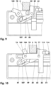
- the Figure 7 shows the delay device (21) with the upper housing shell (33) removed in the Figure 1 shown end position (22).
- the deceleration device (21) is arranged on the furniture body and the driver (2) on a drawer that can be moved relative to it.
- the piston rod (114) of the cylinder-piston unit (111) is retracted.
- the driver element (61) is in the end position (22).
- the driver (2) sits in the driving recess (75) of the driver element (61). It rests on the stop pin (84) of the release lever (82).
- the release lever (82) is supported on the pushing surface (65) of the slide (62). If necessary, the pull pin part (102) can also rest on the driver (2).
- the drawer or the sliding door is, for example, closed when the driving element (61) is in this position.
- the driver (2) pulls the driver element (61) relative to the housing (31) in the opening direction (3).
- the driver (2) rests on the pull pin part (102).
- the pull pin part (102) with the pull pin (104) is prevented from moving relative to the slide (62) in the area adjacent to the end position (22) by means of the pivoting and sliding pins (74, 76) guided in the housing (31) and the guide pins (107).
- the slide (62) also pulls the piston rod (114) with the piston (115) relative to the cylinder (113) in this direction.
- the slide (62) can become detached from the piston rod (114) when the slide (62) is moved in the opening direction (3).
- the driver (2) loading the pull pin (104) causes a pivoting movement of the pull pin part (102) in the pull pin pivot joint (78).
- the pull pin part (102) with the pull pin (104) pivots through a pivot angle of between 90 degrees and 110 degrees. In the exemplary embodiment, the pivot angle is 95 degrees.
- the guide pins (107) dip into the widening (47).
- the pull pin part (102) is pivoted further.
- the guide pin (107) moves into the wedge-shaped receptacle (48). Here it is clamped, for example.
- the pivot angle of the pull pin (104) is thus limited by means of the wedge-shaped receptacle (48).
- the guide pins (107) block in this parking position (23), see Figure 8 , pivoting of the drawbar part (102) and a movement of the slide (62).
- the release lever (82) can rest with its actuating arm (85) on the pull pin part (102).
- the driver (2) has left the deceleration device (21).
- the driver element (61) is in the force- and/or form-locking secured parking position (23).
- the drawer can now be opened further with almost no resistance.
- the release lever (82) is in a standby position (88). For example, it rests on the slide (62) with a line of its rear side (89) oriented in the transverse direction (27).
- the piston rod (114) of the cylinder-piston unit (111) is extended.
- the wedge holder (48) for a locking pin of the pull pin part (102) can be arranged in the slide (62).
- the driver (2) moves relative to the delay device (21) in the closing direction (4).
- the driver element (61) initially remains in the position shown in the Figure 8 shown parking position (23).
- the driver (2) moves, for example, above the pull pin part (102) without touching it.
- the driver (2) contacts the stop pin (84) of the release lever (82).
- the release lever (82) is pivoted about the release lever pivot joint (77).
- the stop pin (84) is pressed against the push surface (65) of the slide (62).
- the piston rod (114) of the cylinder-piston unit (111) is loaded centrally.
- the side of the driver (2) oriented towards the slide (62), e.g.
- the slide (62) loaded in the closing direction (4) also pulls the tie pin part (102) in this direction.
- the guide pins (107) of the tie pin part (102) move along the housing-side guide slots (55).
- the tie pin part (102) is pivoted about the tie pin swivel joint (79).
- the slide (62) loads the piston rod (114) of the cylinder-piston unit (111).
- the piston (115) is retracted and displaces oil, for example, from the displacement chamber (116) into the compensation chamber (117) in a throttled manner.
- the movement of the driver element (61) is delayed.
- the closing movement of the drawer is braked via the driver (2).
- the Figure 10 shows the driver element (61) as the drawer is closed further.
- the driver element (61) coupled to the driver (2) has moved further in the closing direction (4).
- the piston rod (114) of the cylinder-piston unit (111) has been retracted further.
- the pull pin part (102) has pivoted further in the direction of the operating position (108), in which the pull pin (104) protrudes from the housing (31), see Figure 7.
- the guide pins (107) have moved along the run-in slope (49) of the guide slot (55) in the direction of the horizontal section (51) of the second guide track (44).
- the Figures 11 and 12 show a combined acceleration and deceleration device (10) with the upper housing shell (33) removed.
- the driving element (61) is in the end position (22).
- Figure 12 shows the same combined acceleration and deceleration device (10) with the driving element (61) in the parking position (23).
- the combined acceleration and deceleration device (10) has an acceleration device (11) and a deceleration device (21) cooperating with it.
- the deceleration device (21) is largely constructed in the same way as in connection with the Figures 1 - 10 illustrated embodiment.
- the housing (31) has additional mounting pins (52) for deflection rollers (53) and a tension element holder (54).
- the acceleration device (11) connects the carriage (62) to the housing (31).
- a tension sleeve (12) is mounted in the fork-shaped holder (72) of the carriage (62), in which a tension cable (13) is fastened.
- this tension cable (13) is guided around two deflection rollers (53) of different diameters and is connected by means of a transition sleeve (14) to a spring energy store (15) oriented, for example, in the longitudinal direction (25).
- This spring energy store (15) is, for example, a tension spring (15).
- This tension spring (15) is relaxed to a residual energy value when the driving element (61) is in the end position (22) and tensioned to a maximum operating value when the driving element (61) is in the parking position (23).
- the difference in length between the tensioned and the relaxed spring energy store (15) corresponds, for example, to the stroke of the driving element (61) of the parking position (23) to the end position (22).
- the spring energy accumulator (15) is inserted into the traction element holder (54).
- the spring energy accumulator (15) is longer than the extended cylinder-piston unit (111). This allows the tension spring (15) to be operated in the linear range of the force-displacement characteristic curve.
- the acceleration device (11) can also be designed without a traction cable (13).
- the spring energy storage device (15) can then be guided around the deflection rollers (53) or directly connect the carriage (62) to the housing (31). Another arrangement of the acceleration device (11) is also conceivable.
- the acceleration device (11) in the form of a pulley block.
- a further deflection roller is arranged on the carriage (62). This allows the force on the carriage (62) to be dosed within narrow limits.
- the elements of the deceleration device (21) are first assembled as described above.
- the spring energy storage device (15) is then connected to the traction cable (13).
- This unit is then placed around the deflection rollers (53) and suspended in the carriage (62) and in the housing (31).
- the tension spring (15) then acts on the carriage (62) via the deflection rollers (53).
- the spring energy storage device (15) is thus held on the carriage (62) and the housing (31).
- the guide pins (107) rest against the guide slots (55).
- the force component of the spring force applied to the guide pin (107) and oriented parallel to the guide slot (55) points in the direction of the end position (22).
- the guide pins (107) thus block the position of the driving element (61) relative to the housing (31).
- these guide pins (107) simultaneously secure the position of the pull pin part (102) relative to the slide (62) by clamping in the wedge holder (48).
- the position of the pull pin part (102) relative to the slide (62) in the parking position (23) can be secured by means of a force-fitting and/or form-fitting connection between the pull pin part (102) and the slide (62).
- the driver element (61) is released from the parking position (23) as described in connection with the first embodiment. No impact noises are generated here. In this case too, the force on the push surface (65) is introduced into the cylinder-piston unit (111) without redirection. This avoids damage to the driver element (61) and/or the housing (31).
- both the deceleration force of the deceleration device (21) and an acceleration force caused by the relaxing spring energy store (15) act on the driver element (61). Due to the long tension spring (15), there is a very flat spring characteristic curve. The resultant of the superimposed acceleration and deceleration forces moves the driver element (61) in a controlled manner into the end position (22). It remains here without striking anything.
- the drawer is now closed, for example.
- the driver element (61) When the drawer is opened, the driver element (61) is also pulled in the opening direction (3) in this embodiment.
- the piston (115) is extended in the cylinder-piston unit (111).
- the spring energy store (15) is charged.
- the driver element (61) has reached the parking position (23)
- the driver (2) is decoupled.
- the drawer can now be opened further.
- a two-part carrier element (61) is shown. This can be used both in a deceleration device (21) and in a combined acceleration and deceleration device (10), as described in connection with the previous embodiments.
- the driving element (61) shown has a slide (62) and a double lever (81) pivotably mounted in it.
- the pivot and sliding pins (74, 76) are in this Figure 13 not shown.
- the representation of the Figure 13 shows the driving element (61) in the end position (22).
- the carriage (62) is largely constructed in the same way as the Figure 3 shown slide (62).
- the first sliding and pivot pin holder (67) is arranged below the thrust pin (64).
- the thrust surface (65) is a continuous flat surface. It is arranged normal to the plane of the transverse openings (67, 68). In addition, a normal to the thrust surface (65) penetrates the piston rod head holder (63) or a stop surface of the piston rod (114) on the slide side.
- the double lever (81) is pivotably mounted in the second sliding and pivot pin holder (68) of the slide (62).
- the position of the second sliding and pivot pin holder (68) relative to the thrust surface (65) corresponds, for example, to the conditions of the Figure 3 shown carriage (62).
- oval guide pin (107) lies in a plane parallel to the plane of the sliding and pivot pins (74, 76).
- the guide pin (107) can also be Figure 5 The guide pin (107) shown in FIG.
- the Figure 14 shows the double lever (81) in a side view. It has a pull pin (104) and a stop pin (84).
- the pull pin (104) is designed like the one in the Figure 5 Its arrangement relative to the guide pins (107) also corresponds to the conditions of the Figure 5 shown drawbar part (102).
- the stop pin (84) is formed onto the pull pin (104).
- the stop pin (84) is connected to the pull pin (104) in the area of the guide pin (107).
- the stop pin (84) is curved.
- the imaginary center line of the curve (91) is oriented in the transverse direction (27) and lies above the stop pin (84) when the pull pin (104) is in the operating position (108). In this position of the double lever (81), see. Figure 13 , the stop pin (84) is located below the slide (62). The stop pin (84) is thus at least approximately perpendicular to the pull pin (104).
- the stop pin (84) can be designed to be elastically deformable.
- the arch (91) can be bent open. It is also conceivable to design the connection of the stop pin (84) to the tension pin (104) to be bendable.
- the Figure 15 shows that in the Figures 13 and 14 illustrated driving element (61) in the parking position (23) in a housing bottom shell (32).
- the housing bottom shell (32) is, for example, constructed as described in connection with the previous embodiments.
- the carriage (62) is shown cut along a vertical central longitudinal plane.
- the double lever (81) is pivoted relative to the end position (22), e.g. by an angle of 95 degrees.
- the pivoting direction of the pull pin is oriented in the opening direction (3) when pivoting into the parking position (23).
- the pull pin (104) In the parking position (23) the pull pin (104) has the same position relative to the slide (62) as in the pull pin (104) described in connection with the previous embodiments.
- the guide pins (107) are secured in the wedge-shaped receptacles (48) of the second guide tracks (44). This both fixes the parking position (23) and blocks the driving element (61) from being moved in the closing direction (4).
- the stop pin (84) protrudes from the slide (62) by a third of its length. It protrudes into the drive recess (75). The part of the stop pin (84) protruding from the slide (62) is offset in the direction of the thrust surface (65) from the second pivoting and sliding pin (76).
- the driver (2) When the driver (2) moves relative to the driver element (61) in the closing direction (4), the driver (2) first contacts the stop pin (84).
- the double lever (81) experiences a torque about the swivel joint (78) with the second sliding and swivel pin (76).
- the double lever (81) is swiveled clockwise. This releases the locking of the double lever (81), e.g. in the housing (31).
- the double lever (81) leaves the parking position (23).
- the pull pin (104) swiveled with the double lever (81) limits the play of the driver (2) relative to the driver element (61) in the opening direction (3).
- the stop pin (84) is displaced into the carriage (62).
- the guide pins (107) roll on the guide slots (55).
- the double lever (81) is pivoted further.
- the driver element (61) moves in the direction of the end position (22).
- the deceleration device (21) and, if applicable, the acceleration device (11) act on the driver element (61), as described above.
Landscapes
- Transmission Devices (AREA)
- Braking Arrangements (AREA)
- Fluid-Damping Devices (AREA)
Claims (10)
- Dispositif de temporisation (21), pourvu d'un carter (31), pourvu d'une unité piston / cylindre (111) logée dans le carter (31) comportant un cylindre (113) et un piston (115) et pourvu d'un élément entraîneur (61) logé dans le carter (31) en étant déplaçable entre une position de repos (23) sécurisée par complémentarité de force et / ou de forme et une position finale (22) et en retour, au moins lors du déplacement dans la direction de la position finale (22), l'élément entraîneur (61) contraignant le piston (115) par rapport au cylindre (113) et l'élément entraîneur (61) comprenant un chariot (62) doté d'un premier tenon de glissement et de pivotement (74) et d'un tenon de traction (104) logé en pivotement sur celui-ci dans une articulation pivotante (78), doté d'un deuxième tenon de glissement et de pivotement (76), les tenons de glissement et de pivotement (74, 76) étant insérés dans une première voie de guidage (43), orientée dans la direction longitudinale (25) du dispositif de temporisation (21) et le tenon de traction (104) étant relié de manière rigide avec au moins un tenon de guidage (107) guidé dans le carter (31), déplaçable au moins dans un segment de course adjacent à la position finale (22), à la parallèle du chariot (62), caractérisé- en ce qu'un tenon de butée (84) est logé de manière pivotante dans le chariot (62),- en ce que le tenon de guidage (107) est inséré dans une deuxième voie de guidage (44) comprenant un segment (51) horizontal et un évasement (47) placé sur une extrémité opposée à un logement de cylindre (39) pour l'unité piston / cylindre (111), dirigée dans la direction opposée à la première voie de guidage (43),- en ce que le carter (31) ou le chariot (62) possède un logement (48) cunéiforme, qui délimite la zone de l'angle de pivotement du tenon de traction (104) dans la position de repos (23),- en ce que l'ouverture du logement (48) cunéiforme est orientée dans la direction opposée au logement de cylindre (39), de sorte que le tenon de guidage (107) puisse être serré dans le logement (48) cunéiforme,- en ce que l'angle de pivotement du tenon de traction (104) est supérieur à 90 degrés et est inférieur à 110 degrés et- en ce qu'au moyen d'un déplacement en pivotement du tenon de butée (84), le tenon de traction (104) est susceptible d'être repoussé par rapport au chariot (62) hors de la position de repos (23).
- Dispositif de temporisation (21) selon la revendication 1, caractérisé en ce que le logement (48) cunéiforme possède un angle d'ouverture compris entre 10 degrés et 30 degrés.
- Dispositif de temporisation (21) selon la revendication 1, caractérisé en ce que le tenon de butée (84) est susceptible de s'appuyer sur une surface de poussée (65) du chariot (62).
- Dispositif de temporisation (21) selon la revendication 3, caractérisé en ce que l'unité piston / cylindre (111) possède un axe médian (122) orienté à la normale la surface de poussée (65).
- Dispositif de temporisation (21) selon la revendication 1, caractérisé en ce que le tenon de butée (84) est surmoulé sur le tenon de traction (104).
- Dispositif de temporisation (21) selon la revendication 5, caractérisé en ce que le tenon de butée (84) est conçu en étant élastiquement déformable.
- Dispositif mixte d'accélération et de temporisation (10), pourvu d'un dispositif de temporisation (21) selon la revendication 1 et pourvu d'un accumulateur d'énergie (15) élastique susceptible d'être chargé et déchargé de manière répétitive, lorsque l'élément entraîneur (61) se trouve dans la position de repos (23), l'accumulateur d'énergie (15) élastique étant chargé et lorsque l'élément entraîneur (61) se trouve dans la position finale (22), étant déchargé à une valeur d'énergie résiduelle et l'accumulateur d'énergie (15) élastique contraignant l'élément entraîneur (61) en direction de la position finale (22), caractérisé- en ce que l'accumulateur d'énergie (15) élastique est maintenu sur le chariot (62) et sur le carter (31),- en ce que dans la position de repos (23), le tenon de guidage (107) s'appuie sur une coulisse de guidage (55) du carter (31) et- en ce que dans la position de repos (23), la composante de force de la force élastique, appliquée sur le tenon de guidage (107), orientée à la parallèle de la coulisse de guidage (55) montre dans la direction de la position finale (22), de telle sorte que le carter (31) bloque un déplacement longitudinal de l'élément entraîneur (61).
- Dispositif mixte d'accélération et de temporisation (10) selon la revendication 7, caractérisé en ce que la coulisse de guidage (55) est une partie d'une voie de guidage (44) et en ce que le logement (48) cunéiforme est constitué dans ladite voie de guidage (44).
- Dispositif mixte d'accélération et de temporisation (10) selon la revendication 8, caractérisé en ce que le tenon de guidage (107) est susceptible d'être réceptionné dans le logement (48) cunéiforme.
- Dispositif mixte d'accélération et de temporisation (10) selon la revendication 7, caractérisé en ce que l'accumulateur d'énergie (15) élastique est placé en série avec un câble de traction (13) guidé le long d'au moins un galet de renvoi (53).
Applications Claiming Priority (2)
| Application Number | Priority Date | Filing Date | Title |
|---|---|---|---|
| DE102018008207.6A DE102018008207B4 (de) | 2018-10-14 | 2018-10-14 | Verzögerungsvorrichtung mit mehrteiligem Mitnahmeelement |
| PCT/DE2019/000265 WO2020078494A1 (fr) | 2018-10-14 | 2019-10-13 | Dispositif de ralentissement présentant un élément d'entraînement en plusieurs parties |
Publications (2)
| Publication Number | Publication Date |
|---|---|
| EP3864246A1 EP3864246A1 (fr) | 2021-08-18 |
| EP3864246B1 true EP3864246B1 (fr) | 2024-06-12 |
Family
ID=68696187
Family Applications (1)
| Application Number | Title | Priority Date | Filing Date |
|---|---|---|---|
| EP19809376.7A Active EP3864246B1 (fr) | 2018-10-14 | 2019-10-13 | Dispositif de ralentissement présentant un élément d'entraînement en plusieurs parties |
Country Status (5)
| Country | Link |
|---|---|
| EP (1) | EP3864246B1 (fr) |
| DE (1) | DE102018008207B4 (fr) |
| ES (1) | ES2986848T3 (fr) |
| PL (1) | PL3864246T3 (fr) |
| WO (1) | WO2020078494A1 (fr) |
Family Cites Families (7)
| Publication number | Priority date | Publication date | Assignee | Title |
|---|---|---|---|---|
| WO2007111424A1 (fr) | 2006-03-27 | 2007-10-04 | Yoon Sik Park | Moyen de fermeture automatique |
| DE202007019190U1 (de) | 2007-02-20 | 2011-02-10 | Karl Simon Gmbh & Co. Kg | Einzugvorrichtung für Schiebelemente |
| TWM335193U (en) | 2007-12-31 | 2008-07-01 | Nan Juen Int Co Ltd | Structure for automatic retractable slide rail of drawer |
| DE102008009046B4 (de) | 2008-02-13 | 2014-10-02 | Günther Zimmer | Beschleunigungs- und Verzögerungsvorrichtung mit zwei Mitnahmeelementen |
| MY155806A (en) | 2010-07-29 | 2015-11-30 | Harn Marketing Sdn Bhd | Drawer guide rail system |
| DE102011010778B4 (de) | 2011-02-09 | 2017-03-23 | Günther Zimmer | Beschleunigungs- und Verzögerungsvorrichtung mit Mitnahmeelement-Schwenkgelenk sowie ein System mit zwei ein Zug- und Abbremsvorrichtungspaar bildende Beschleunigungs- und Verzögerungsvorrichtungen |
| DE102016007872B4 (de) | 2016-06-29 | 2019-10-24 | Günther Zimmer | Einzugsvorrichtung für Objekte mit großer Massenträgheit |
-
2018
- 2018-10-14 DE DE102018008207.6A patent/DE102018008207B4/de active Active
-
2019
- 2019-10-13 EP EP19809376.7A patent/EP3864246B1/fr active Active
- 2019-10-13 WO PCT/DE2019/000265 patent/WO2020078494A1/fr not_active Ceased
- 2019-10-13 ES ES19809376T patent/ES2986848T3/es active Active
- 2019-10-13 PL PL19809376.7T patent/PL3864246T3/pl unknown
Also Published As
| Publication number | Publication date |
|---|---|
| ES2986848T3 (es) | 2024-11-12 |
| DE102018008207A1 (de) | 2020-04-16 |
| EP3864246A1 (fr) | 2021-08-18 |
| PL3864246T3 (pl) | 2024-10-28 |
| WO2020078494A1 (fr) | 2020-04-23 |
| DE102018008207B4 (de) | 2023-11-09 |
Similar Documents
| Publication | Publication Date | Title |
|---|---|---|
| EP2673443B1 (fr) | Dispositif d'accélération et de ralentissement doté d'un élément d'entraînement à articulation pivotante | |
| EP3070248B1 (fr) | Dispositif d'acceleration et de retard combine avec protection contre la surcharge | |
| EP3070251B1 (fr) | Dispositif d'acceleration et de retard avec protection mouvement silencieux | |
| EP2373195B1 (fr) | Dispositif de rentrée automatique et glissière | |
| EP3864245B1 (fr) | Dispositif d'entraînement pour deux positions d'extrémité | |
| EP3581746B1 (fr) | Dispositif combiné d'amortissement et de fermeture pour une porte centrale | |
| EP3341545B1 (fr) | Dispositif de positionnement de deux portes coulissantes et meuble | |
| WO2005044046A1 (fr) | Mecanisme de retrait automatique destine a des guides de tiroirs | |
| EP3863474B1 (fr) | Dispositif d'attelage avec ressort de stockage d'énergie détachable | |
| EP3478916B1 (fr) | Dispositif d'alimentation d'objets à grande inertie | |
| WO2020078492A1 (fr) | Dispositif de fermeture automatique à dispositif de charge d'accumulateur | |
| DE20318929U1 (de) | Einzugsautomatik für Schubladen-Ausziehführungen | |
| DE102010047485A1 (de) | Mitteltür-Zuziehvorrichtung | |
| EP3062661B1 (fr) | Dispositif pour ouvrir une partie de meuble mobile | |
| DE4108078A1 (de) | Riegelverschluss | |
| DE102022003806B4 (de) | Einzugs- und Auszugsvorrichtung mit zwei schaltbaren Axialkupplungen | |
| EP3461980B1 (fr) | Unité de déclenchement et pièce de meuble dotée d'une telle unité | |
| DE102018008207B4 (de) | Verzögerungsvorrichtung mit mehrteiligem Mitnahmeelement | |
| EP3478917B1 (fr) | Dispositif de fermeture d'une porte centrale comprenant des coulisseaux de transfert | |
| WO2022117134A2 (fr) | Dispositif de rétraction doté d'un dispositif d'amortissement | |
| DE102022003805B4 (de) | Einzugs- und Auszugsvorrichtung mit bidirektionalen Einzugsvorrichtungen | |
| DE102018008204B4 (de) | Einzugsvorrichtung mit Auszugsunterstützung | |
| DE102005043707A1 (de) | Optimiertes Aufprallsystem für 10°-Lastfall | |
| EP3863473B1 (fr) | Dispositif de fermeture automatique à accumulateur d'énergie de ressort à direction inversée | |
| WO2006087057A1 (fr) | Dispositif d'amortissement et de serrage pour deux parties d'un meuble |
Legal Events
| Date | Code | Title | Description |
|---|---|---|---|
| STAA | Information on the status of an ep patent application or granted ep patent |
Free format text: STATUS: UNKNOWN |
|
| STAA | Information on the status of an ep patent application or granted ep patent |
Free format text: STATUS: THE INTERNATIONAL PUBLICATION HAS BEEN MADE |
|
| PUAI | Public reference made under article 153(3) epc to a published international application that has entered the european phase |
Free format text: ORIGINAL CODE: 0009012 |
|
| STAA | Information on the status of an ep patent application or granted ep patent |
Free format text: STATUS: REQUEST FOR EXAMINATION WAS MADE |
|
| 17P | Request for examination filed |
Effective date: 20210511 |
|
| AK | Designated contracting states |
Kind code of ref document: A1 Designated state(s): AL AT BE BG CH CY CZ DE DK EE ES FI FR GB GR HR HU IE IS IT LI LT LU LV MC MK MT NL NO PL PT RO RS SE SI SK SM TR |
|
| DAV | Request for validation of the european patent (deleted) | ||
| DAX | Request for extension of the european patent (deleted) | ||
| GRAP | Despatch of communication of intention to grant a patent |
Free format text: ORIGINAL CODE: EPIDOSNIGR1 |
|
| STAA | Information on the status of an ep patent application or granted ep patent |
Free format text: STATUS: GRANT OF PATENT IS INTENDED |
|
| INTG | Intention to grant announced |
Effective date: 20240112 |
|
| GRAS | Grant fee paid |
Free format text: ORIGINAL CODE: EPIDOSNIGR3 |
|
| GRAA | (expected) grant |
Free format text: ORIGINAL CODE: 0009210 |
|
| STAA | Information on the status of an ep patent application or granted ep patent |
Free format text: STATUS: THE PATENT HAS BEEN GRANTED |
|
| AK | Designated contracting states |
Kind code of ref document: B1 Designated state(s): AL AT BE BG CH CY CZ DE DK EE ES FI FR GB GR HR HU IE IS IT LI LT LU LV MC MK MT NL NO PL PT RO RS SE SI SK SM TR |
|
| REG | Reference to a national code |
Ref country code: GB Ref legal event code: FG4D Free format text: NOT ENGLISH |
|
| REG | Reference to a national code |
Ref country code: CH Ref legal event code: EP |
|
| REG | Reference to a national code |
Ref country code: DE Ref legal event code: R096 Ref document number: 502019011456 Country of ref document: DE |
|
| REG | Reference to a national code |
Ref country code: IE Ref legal event code: FG4D Free format text: LANGUAGE OF EP DOCUMENT: GERMAN |
|
| PG25 | Lapsed in a contracting state [announced via postgrant information from national office to epo] |
Ref country code: BG Free format text: LAPSE BECAUSE OF FAILURE TO SUBMIT A TRANSLATION OF THE DESCRIPTION OR TO PAY THE FEE WITHIN THE PRESCRIBED TIME-LIMIT Effective date: 20240612 |
|
| PG25 | Lapsed in a contracting state [announced via postgrant information from national office to epo] |
Ref country code: HR Free format text: LAPSE BECAUSE OF FAILURE TO SUBMIT A TRANSLATION OF THE DESCRIPTION OR TO PAY THE FEE WITHIN THE PRESCRIBED TIME-LIMIT Effective date: 20240612 Ref country code: FI Free format text: LAPSE BECAUSE OF FAILURE TO SUBMIT A TRANSLATION OF THE DESCRIPTION OR TO PAY THE FEE WITHIN THE PRESCRIBED TIME-LIMIT Effective date: 20240612 |
|
| REG | Reference to a national code |
Ref country code: LT Ref legal event code: MG9D |
|
| PG25 | Lapsed in a contracting state [announced via postgrant information from national office to epo] |
Ref country code: GR Free format text: LAPSE BECAUSE OF FAILURE TO SUBMIT A TRANSLATION OF THE DESCRIPTION OR TO PAY THE FEE WITHIN THE PRESCRIBED TIME-LIMIT Effective date: 20240913 |
|
| REG | Reference to a national code |
Ref country code: NL Ref legal event code: MP Effective date: 20240612 |
|
| PG25 | Lapsed in a contracting state [announced via postgrant information from national office to epo] |
Ref country code: LV Free format text: LAPSE BECAUSE OF FAILURE TO SUBMIT A TRANSLATION OF THE DESCRIPTION OR TO PAY THE FEE WITHIN THE PRESCRIBED TIME-LIMIT Effective date: 20240612 |
|
| PG25 | Lapsed in a contracting state [announced via postgrant information from national office to epo] |
Ref country code: NO Free format text: LAPSE BECAUSE OF FAILURE TO SUBMIT A TRANSLATION OF THE DESCRIPTION OR TO PAY THE FEE WITHIN THE PRESCRIBED TIME-LIMIT Effective date: 20240912 Ref country code: LV Free format text: LAPSE BECAUSE OF FAILURE TO SUBMIT A TRANSLATION OF THE DESCRIPTION OR TO PAY THE FEE WITHIN THE PRESCRIBED TIME-LIMIT Effective date: 20240612 Ref country code: HR Free format text: LAPSE BECAUSE OF FAILURE TO SUBMIT A TRANSLATION OF THE DESCRIPTION OR TO PAY THE FEE WITHIN THE PRESCRIBED TIME-LIMIT Effective date: 20240612 Ref country code: GR Free format text: LAPSE BECAUSE OF FAILURE TO SUBMIT A TRANSLATION OF THE DESCRIPTION OR TO PAY THE FEE WITHIN THE PRESCRIBED TIME-LIMIT Effective date: 20240913 Ref country code: FI Free format text: LAPSE BECAUSE OF FAILURE TO SUBMIT A TRANSLATION OF THE DESCRIPTION OR TO PAY THE FEE WITHIN THE PRESCRIBED TIME-LIMIT Effective date: 20240612 Ref country code: BG Free format text: LAPSE BECAUSE OF FAILURE TO SUBMIT A TRANSLATION OF THE DESCRIPTION OR TO PAY THE FEE WITHIN THE PRESCRIBED TIME-LIMIT Effective date: 20240612 Ref country code: RS Free format text: LAPSE BECAUSE OF FAILURE TO SUBMIT A TRANSLATION OF THE DESCRIPTION OR TO PAY THE FEE WITHIN THE PRESCRIBED TIME-LIMIT Effective date: 20240912 |
|
| REG | Reference to a national code |
Ref country code: ES Ref legal event code: FG2A Ref document number: 2986848 Country of ref document: ES Kind code of ref document: T3 Effective date: 20241112 |
|
| PG25 | Lapsed in a contracting state [announced via postgrant information from national office to epo] |
Ref country code: NL Free format text: LAPSE BECAUSE OF FAILURE TO SUBMIT A TRANSLATION OF THE DESCRIPTION OR TO PAY THE FEE WITHIN THE PRESCRIBED TIME-LIMIT Effective date: 20240612 |
|
| PG25 | Lapsed in a contracting state [announced via postgrant information from national office to epo] |
Ref country code: NL Free format text: LAPSE BECAUSE OF FAILURE TO SUBMIT A TRANSLATION OF THE DESCRIPTION OR TO PAY THE FEE WITHIN THE PRESCRIBED TIME-LIMIT Effective date: 20240612 |
|
| PG25 | Lapsed in a contracting state [announced via postgrant information from national office to epo] |
Ref country code: PT Free format text: LAPSE BECAUSE OF FAILURE TO SUBMIT A TRANSLATION OF THE DESCRIPTION OR TO PAY THE FEE WITHIN THE PRESCRIBED TIME-LIMIT Effective date: 20241014 |
|
| PG25 | Lapsed in a contracting state [announced via postgrant information from national office to epo] |
Ref country code: PT Free format text: LAPSE BECAUSE OF FAILURE TO SUBMIT A TRANSLATION OF THE DESCRIPTION OR TO PAY THE FEE WITHIN THE PRESCRIBED TIME-LIMIT Effective date: 20241014 |
|
| PG25 | Lapsed in a contracting state [announced via postgrant information from national office to epo] |
Ref country code: EE Free format text: LAPSE BECAUSE OF FAILURE TO SUBMIT A TRANSLATION OF THE DESCRIPTION OR TO PAY THE FEE WITHIN THE PRESCRIBED TIME-LIMIT Effective date: 20240612 |
|
| PG25 | Lapsed in a contracting state [announced via postgrant information from national office to epo] |
Ref country code: IS Free format text: LAPSE BECAUSE OF FAILURE TO SUBMIT A TRANSLATION OF THE DESCRIPTION OR TO PAY THE FEE WITHIN THE PRESCRIBED TIME-LIMIT Effective date: 20241012 |
|
| PG25 | Lapsed in a contracting state [announced via postgrant information from national office to epo] |
Ref country code: CZ Free format text: LAPSE BECAUSE OF FAILURE TO SUBMIT A TRANSLATION OF THE DESCRIPTION OR TO PAY THE FEE WITHIN THE PRESCRIBED TIME-LIMIT Effective date: 20240612 |
|
| PG25 | Lapsed in a contracting state [announced via postgrant information from national office to epo] |
Ref country code: RO Free format text: LAPSE BECAUSE OF FAILURE TO SUBMIT A TRANSLATION OF THE DESCRIPTION OR TO PAY THE FEE WITHIN THE PRESCRIBED TIME-LIMIT Effective date: 20240612 Ref country code: SK Free format text: LAPSE BECAUSE OF FAILURE TO SUBMIT A TRANSLATION OF THE DESCRIPTION OR TO PAY THE FEE WITHIN THE PRESCRIBED TIME-LIMIT Effective date: 20240612 |
|
| PG25 | Lapsed in a contracting state [announced via postgrant information from national office to epo] |
Ref country code: SM Free format text: LAPSE BECAUSE OF FAILURE TO SUBMIT A TRANSLATION OF THE DESCRIPTION OR TO PAY THE FEE WITHIN THE PRESCRIBED TIME-LIMIT Effective date: 20240612 |
|
| PG25 | Lapsed in a contracting state [announced via postgrant information from national office to epo] |
Ref country code: SM Free format text: LAPSE BECAUSE OF FAILURE TO SUBMIT A TRANSLATION OF THE DESCRIPTION OR TO PAY THE FEE WITHIN THE PRESCRIBED TIME-LIMIT Effective date: 20240612 Ref country code: SK Free format text: LAPSE BECAUSE OF FAILURE TO SUBMIT A TRANSLATION OF THE DESCRIPTION OR TO PAY THE FEE WITHIN THE PRESCRIBED TIME-LIMIT Effective date: 20240612 Ref country code: RO Free format text: LAPSE BECAUSE OF FAILURE TO SUBMIT A TRANSLATION OF THE DESCRIPTION OR TO PAY THE FEE WITHIN THE PRESCRIBED TIME-LIMIT Effective date: 20240612 Ref country code: IS Free format text: LAPSE BECAUSE OF FAILURE TO SUBMIT A TRANSLATION OF THE DESCRIPTION OR TO PAY THE FEE WITHIN THE PRESCRIBED TIME-LIMIT Effective date: 20241012 Ref country code: EE Free format text: LAPSE BECAUSE OF FAILURE TO SUBMIT A TRANSLATION OF THE DESCRIPTION OR TO PAY THE FEE WITHIN THE PRESCRIBED TIME-LIMIT Effective date: 20240612 Ref country code: CZ Free format text: LAPSE BECAUSE OF FAILURE TO SUBMIT A TRANSLATION OF THE DESCRIPTION OR TO PAY THE FEE WITHIN THE PRESCRIBED TIME-LIMIT Effective date: 20240612 |
|
| REG | Reference to a national code |
Ref country code: DE Ref legal event code: R097 Ref document number: 502019011456 Country of ref document: DE |
|
| PG25 | Lapsed in a contracting state [announced via postgrant information from national office to epo] |
Ref country code: DK Free format text: LAPSE BECAUSE OF FAILURE TO SUBMIT A TRANSLATION OF THE DESCRIPTION OR TO PAY THE FEE WITHIN THE PRESCRIBED TIME-LIMIT Effective date: 20240612 |
|
| PLBE | No opposition filed within time limit |
Free format text: ORIGINAL CODE: 0009261 |
|
| STAA | Information on the status of an ep patent application or granted ep patent |
Free format text: STATUS: NO OPPOSITION FILED WITHIN TIME LIMIT |
|
| 26N | No opposition filed |
Effective date: 20250313 |
|
| REG | Reference to a national code |
Ref country code: CH Ref legal event code: PL |
|
| PG25 | Lapsed in a contracting state [announced via postgrant information from national office to epo] |
Ref country code: MC Free format text: LAPSE BECAUSE OF FAILURE TO SUBMIT A TRANSLATION OF THE DESCRIPTION OR TO PAY THE FEE WITHIN THE PRESCRIBED TIME-LIMIT Effective date: 20240612 |
|
| PG25 | Lapsed in a contracting state [announced via postgrant information from national office to epo] |
Ref country code: LU Free format text: LAPSE BECAUSE OF NON-PAYMENT OF DUE FEES Effective date: 20241013 Ref country code: BE Free format text: LAPSE BECAUSE OF NON-PAYMENT OF DUE FEES Effective date: 20241031 |
|
| PG25 | Lapsed in a contracting state [announced via postgrant information from national office to epo] |
Ref country code: CH Free format text: LAPSE BECAUSE OF NON-PAYMENT OF DUE FEES Effective date: 20241031 |
|
| REG | Reference to a national code |
Ref country code: BE Ref legal event code: MM Effective date: 20241031 |
|
| PG25 | Lapsed in a contracting state [announced via postgrant information from national office to epo] |
Ref country code: SE Free format text: LAPSE BECAUSE OF FAILURE TO SUBMIT A TRANSLATION OF THE DESCRIPTION OR TO PAY THE FEE WITHIN THE PRESCRIBED TIME-LIMIT Effective date: 20240612 |
|
| PGFP | Annual fee paid to national office [announced via postgrant information from national office to epo] |
Ref country code: PL Payment date: 20250923 Year of fee payment: 7 |
|
| PG25 | Lapsed in a contracting state [announced via postgrant information from national office to epo] |
Ref country code: IE Free format text: LAPSE BECAUSE OF NON-PAYMENT OF DUE FEES Effective date: 20241013 |
|
| REG | Reference to a national code |
Ref country code: AT Ref legal event code: MM01 Ref document number: 1694382 Country of ref document: AT Kind code of ref document: T Effective date: 20241013 |
|
| PGFP | Annual fee paid to national office [announced via postgrant information from national office to epo] |
Ref country code: DE Payment date: 20251014 Year of fee payment: 7 |
|
| PGFP | Annual fee paid to national office [announced via postgrant information from national office to epo] |
Ref country code: GB Payment date: 20251024 Year of fee payment: 7 |
|
| PG25 | Lapsed in a contracting state [announced via postgrant information from national office to epo] |
Ref country code: AT Free format text: LAPSE BECAUSE OF NON-PAYMENT OF DUE FEES Effective date: 20241013 |
|
| PGFP | Annual fee paid to national office [announced via postgrant information from national office to epo] |
Ref country code: IT Payment date: 20251030 Year of fee payment: 7 |
|
| PGFP | Annual fee paid to national office [announced via postgrant information from national office to epo] |
Ref country code: FR Payment date: 20251024 Year of fee payment: 7 |
|
| PGFP | Annual fee paid to national office [announced via postgrant information from national office to epo] |
Ref country code: TR Payment date: 20251007 Year of fee payment: 7 |
|
| PG25 | Lapsed in a contracting state [announced via postgrant information from national office to epo] |
Ref country code: CY Free format text: LAPSE BECAUSE OF FAILURE TO SUBMIT A TRANSLATION OF THE DESCRIPTION OR TO PAY THE FEE WITHIN THE PRESCRIBED TIME-LIMIT; INVALID AB INITIO Effective date: 20191013 |
|
| PGFP | Annual fee paid to national office [announced via postgrant information from national office to epo] |
Ref country code: ES Payment date: 20251103 Year of fee payment: 7 |
|
| PG25 | Lapsed in a contracting state [announced via postgrant information from national office to epo] |
Ref country code: HU Free format text: LAPSE BECAUSE OF FAILURE TO SUBMIT A TRANSLATION OF THE DESCRIPTION OR TO PAY THE FEE WITHIN THE PRESCRIBED TIME-LIMIT; INVALID AB INITIO Effective date: 20191013 |