EP3864373B1 - Photonische integrierte schaltungen, faseroptische gyroscope und verfahren zu deren herstellung - Google Patents
Photonische integrierte schaltungen, faseroptische gyroscope und verfahren zu deren herstellung Download PDFInfo
- Publication number
- EP3864373B1 EP3864373B1 EP19795412.6A EP19795412A EP3864373B1 EP 3864373 B1 EP3864373 B1 EP 3864373B1 EP 19795412 A EP19795412 A EP 19795412A EP 3864373 B1 EP3864373 B1 EP 3864373B1
- Authority
- EP
- European Patent Office
- Prior art keywords
- waveguide
- branch
- interferometric
- polarizer
- junction
- Prior art date
- Legal status (The legal status is an assumption and is not a legal conclusion. Google has not performed a legal analysis and makes no representation as to the accuracy of the status listed.)
- Active
Links
Images




Classifications
-
- G—PHYSICS
- G01—MEASURING; TESTING
- G01C—MEASURING DISTANCES, LEVELS OR BEARINGS; SURVEYING; NAVIGATION; GYROSCOPIC INSTRUMENTS; PHOTOGRAMMETRY OR VIDEOGRAMMETRY
- G01C19/00—Gyroscopes; Turn-sensitive devices using vibrating masses; Turn-sensitive devices without moving masses; Measuring angular rate using gyroscopic effects
- G01C19/58—Turn-sensitive devices without moving masses
- G01C19/64—Gyrometers using the Sagnac effect, i.e. rotation-induced shifts between counter-rotating electromagnetic beams
- G01C19/72—Gyrometers using the Sagnac effect, i.e. rotation-induced shifts between counter-rotating electromagnetic beams with counter-rotating light beams in a passive ring, e.g. fibre laser gyrometers
- G01C19/721—Details, e.g. optical or electronical details
-
- G—PHYSICS
- G02—OPTICS
- G02B—OPTICAL ELEMENTS, SYSTEMS OR APPARATUS
- G02B6/00—Light guides; Structural details of arrangements comprising light guides and other optical elements, e.g. couplings
- G02B6/24—Coupling light guides
- G02B6/26—Optical coupling means
- G02B6/28—Optical coupling means having data bus means, i.e. plural waveguides interconnected and providing an inherently bidirectional system by mixing and splitting signals
- G02B6/293—Optical coupling means having data bus means, i.e. plural waveguides interconnected and providing an inherently bidirectional system by mixing and splitting signals with wavelength selective means
- G02B6/29302—Optical coupling means having data bus means, i.e. plural waveguides interconnected and providing an inherently bidirectional system by mixing and splitting signals with wavelength selective means based on birefringence or polarisation, e.g. wavelength dependent birefringence, polarisation interferometers
-
- G—PHYSICS
- G02—OPTICS
- G02B—OPTICAL ELEMENTS, SYSTEMS OR APPARATUS
- G02B6/00—Light guides; Structural details of arrangements comprising light guides and other optical elements, e.g. couplings
- G02B6/24—Coupling light guides
- G02B6/42—Coupling light guides with opto-electronic elements
-
- G—PHYSICS
- G02—OPTICS
- G02B—OPTICAL ELEMENTS, SYSTEMS OR APPARATUS
- G02B6/00—Light guides; Structural details of arrangements comprising light guides and other optical elements, e.g. couplings
- G02B6/24—Coupling light guides
- G02B6/42—Coupling light guides with opto-electronic elements
- G02B6/4201—Packages, e.g. shape, construction, internal or external details
- G02B6/4204—Packages, e.g. shape, construction, internal or external details the coupling comprising intermediate optical elements, e.g. lenses, holograms
- G02B6/4213—Packages, e.g. shape, construction, internal or external details the coupling comprising intermediate optical elements, e.g. lenses, holograms the intermediate optical elements being polarisation selective optical elements
Definitions
- Fiber Optic Gyroscopes FOGs
- accelerometers FOG-based inertial navigation systems
- INSs FOG-based inertial navigation systems
- An INS is used to sense the location and the orientation of the vehicle.
- the vehicles may use a combination of the Global Positioning System (GPS) and INS.
- GPS Global Positioning System
- the accuracy of GPS systems has improved significantly since the year 2000.
- the GPS system specifies a signal that facilitates a global average user range error (URE) of less than 7.8m, with 95% probability. Though actual performance will likely exceed the specification, GPS by itself cannot supply enough accuracy for a position estimation for an autonomous vehicle. GPS, however, provides good long-term stability on position measurement.
- INS can be highly accurate in the short-term, but INS suffers from long-term drift on the position measurement.
- Combining GPS and an INS may be used to overcome the disadvantages of each individual position sensing system. This combined operation becomes even more important in the autonomous car application, since the accuracy of GPS may be degraded near buildings, bridges, and trees. In such environments, a GPS receiver may be unable to obtaining signals from a sufficient number of satellites, resulting in degraded performance. There is a significant concern in urban areas, where skyscrapers create "urban canyons" in which GPS availability may be severely limited. INS may be used to improve the accuracy of GPS and to fill in performance gaps such as those caused by urban canyons. INS that is coupled with GPS can dead-reckon the current position and calculate orientation and velocity continuously without need for external references.
- INS sensors may be fused with GPS signal to detect roll, pitch and heading of a moving car instantaneously. Determination of the exact turning angle is an important task for the autonomous vehicle control system to ensure safety, which demands a highly accurate and stable scale factor of the gyroscope associated with the autonomous vehicle.
- Embodiments of the invention may include an interference fiber optic gyroscope (IFOG) configured to exhibit a scale factor having a stability that exceeds a predetermined stability threshold, and an accuracy that exceeds a predetermined accuracy threshold.
- IFOG interference fiber optic gyroscope
- An example embodiment may include an IFOG component, such as a photonic integrated circuit (PIC) that is based on highly polarization maintaining (PM), single mode waveguide with a Si 3 N 4 core and cladding material comprising SiO 2 .
- PIC photonic integrated circuit
- PM highly polarization maintaining
- Passive functional IFOG components may be integrated onto the PIC, such as low-loss couplers used for a Sagnac interferometer and for a source/detector transceiver, a high propagation extinction ratio (PER) polarizer, highly efficient fiber-connection mode size converters, and one or more features for elimination of stray light.
- PER propagation extinction ratio
- an ultra-thin (e.g., less than or equal to 100nm) Si 3 N 4 waveguide in the PIC provides several benefits.
- a Si 3 N 4 waveguide transmits light in the 830nm wavelength region, and an IFOG has a larger scale factor at such a short operation wavelength, given a specific fiber length and coil size.
- birefringence as large as 0.02 may be realized in a Si 3 N 4 waveguide, and a waveguide with high birefringence may provide substantial phase error suppression.
- a Si 3 N 4 waveguide configured to have an ultrahigh aspect ratio may exhibit an ultralow propagation loss.
- Si 3 N 4 facilitates the inclusion of a source coupler into the PIC, and facilitates circuit layout to a shape conducive to preventing stray light from recoupling. Furthermore, Si 3 N 4 is a well-established material in the microelectronics industry, where it has been used as an electrical and thermal insulator in electric circuits. Fabrication lines associated with Si 3 N 4 processing are quite mature and have a well-known performance history. Si 3 N 4 also features a set of optical properties that makes it an ideal choice for many applications that require integration of photonic devices on an integrated platform.
- FIG. 1 illustrates an example embodiment of an IFOG 100 constructed and arranged according to the invention.
- the IFOG 100 comprises a PIC 102, a fiber array 104, a sensing fiber coil 106, a PZT modulator 108, a light source 110 and a light detector 112.
- the PIC 102 comprises a source Y-junction 114, an interferometric Y-junction 116, and a polarizer 118.
- Each Y-junction comprises a base waveguide that splits into a pair of branch waveguides.
- the base and branch waveguides are highly PM and single mode waveguides.
- Y-junctions may also be referred to herein as couplers.
- a waveguide has the characteristic of being "highly polarization maintaining" by (i) being highly birefringent, and (ii) having low scattering. Specific value ranges of birefringence and scattering are disclosed herein, which correspond to specific threshold values of PM.
- a Sagnac interferometer is formed when the two fiber ends of the sensing fiber coil 106 are connected, through the fiber array 104, to the ends of the two branch waveguides of the interferometric Y-junction 116 in the PIC 102, as shown in FIG. 1 .
- the polarizer 118 connects the base waveguide of the source Y-junction 114 and the base waveguide of the interferometric Y-junction 116.
- the polarizer 118 has an "m" shape.
- the polarizer 118 polarizes the input light from the light source 110 that comes through the source Y-junction 114.
- the polarizer 118 also filters out the cross-coupled erroneous signal in the light returned from the sensing fiber coil 106 by eliminating the TM-mode due to the polarizer's high PER.
- a phase modulator 108 implemented by a fiber wound oscillating Lead Zirconate Titanate (PZT) disk, is incorporated into the sensing fiber coil 106 located close to one end of the sensing fiber coil 106, to form a coil/modulation assembly 120.
- a sinusoidal modulating signal may be applied to the phase modulator 108 in a controlled manner, according to a modulation/demodulation process suitable for stable Sagnac phase shift reading.
- the combinations of the polarizer 118, the interferometric Y-junction 116 and the coil/modulation assembly 120 forms a so-called "minimum configuration" of an IFOG optical system.
- the light along the clock-wise (CW) path and the light along the counterclockwise (CCW) path undergo the same once reflection and once transmission at the interferometric Y-junction 116, and the Sagnac interferometer is constructed to operate with optical reciprocity, which is necessary for a highly stable IFOG.
- Light that is input to and output from the Sagnac interferometer passes through the same polarizer 118 and single mode waveguide.
- this example embodiment forms a single-mode, single-polarization filter. Any signals that are at different state from the input (e.g., a difference either in spatial mode or polarization mode) are undesired and are substantially eliminated by the single-mode, single-polarization filter.
- Mechanisms that produce erroneous non-reciprocal phase shift may perturbate the Sagnac phase shift.
- the described embodiments serve to mitigate or eliminate such mechanisms in the PIC design.
- Such erroneous phase shift signals may be caused, for example, by a slight non-reciprocity of the Y-junction in the PIC.
- the Y-junction effectively operates as a pair of waveguides arranged at an angle with respect to one another, and can be regarded as a two-mode waveguide near the joint point.
- the evanescent waves overlap in a two-mode waveguide, and the fundamental symmetric mode is converted into second order antisymmetric mode and the two lobes of the mode field are split and nearly perfectly guided in the two branch waveguides.
- a fundamental mode is formed and is guided by the base waveguide, while the second-order antisymmetric mode, which is above the cutoff of the waveguide, is radiated into the substrate.
- a single-mode, single-polarizer filter placed at the base waveguide of the interferometric Y-junction, operates to equalize the phase of the light waves transmitted in opposite directions.
- a benefit of a minimum configuration build with PIC architecture is that the polarizer 118 may be substantially aligned with the interferometric Y-junction 116, with a single mode waveguide filter in between. No additional phase error generation occurs at the junction if a high PER polarizer and a single mode waveguide are implemented after base waveguide of the interferometric Y-junction 116.
- An erroneous phase signal may also occur due to light coupled from the operational polarization mode to its orthogonal mode. Since the PM fiber and the PIC waveguide each supports two polarization modes, and the Sagnac interferometer provides two parallel optical paths, any light coupling into the unwanted polarization mode may generate a non-reciprocal parasitic path. Most of the cross-coupling points reside in the fiber coil, but cross-coupling can also occur at the fiber-to-PIC waveguide joints and/or within the path in the PIC (e.g., at the interferometric Y-junction). To stop such non-reciprocal parasitic paths, the polarizer in the single-mode single-polarizer filter is configured to have a substantially high PER.
- the high PER filter cannot eliminate the spurious phase error generated by a cross-coupling by two points placed at about the same distance, within the depolarization length of the fiber, from the interferometric Y-junction 116.
- the polarization cross-coupling at the interferometric Y-junction is negligible because the high birefringence of the waveguide provides excellent polarization maintenance.
- Major polarization couplings happen at the connection points of the coil fibers to the PIC.
- one of the branch waveguides of the interferometric Y-junction is configured to be longer than the other branch, to supply a fixed phase shifter between the connection points.
- the length of the phase shifter is configured to be longer than the depolarization length, which, in the example embodiment, is approximately 1.8mm.
- reflections at the two connection points may also produce an erroneous phase signal, because the two reflections at the connection interfaces and the interferometric Y-junction form a Michelson interferometer.
- the path difference of the two branch waveguides is larger than decoherence length, the erroneous phase can be avoided.
- the decoherence length of the waveguide of the example embodiment is approximately 28 ⁇ m, so the path difference of the two branch waveguides is configured to be at least 28 ⁇ m.
- Another erroneous phase signal is specific to a multifunction optic integrated circuit (MIOC) fabricated on a LiNbO 3 substrate.
- MIOC multifunction optic integrated circuit
- the LiNbO 3 MIOC has been widely used in commercial FOG products.
- increasing its degree of integration by fitting two Y-junctions into a single circuit has not been successful, because the in-plane birefringence of the crystalline LiNbO 3 substrate limits the degree of freedom of the optic circuit layout, so that the two Y-junctions must be placed in a straight line.
- Unguided radiation (occurring along the base waveguides of the Y-junctions due to the asymmetric mode from the interferometric Y-junction) is received by each of the branch waveguide of the source Y-junction.
- the waveguide that connects the base waveguides configured to form a 180° path loop as shown in FIG. 1 .
- the polarizer 118 which connects the source Y-junction 114 to the interferometric Y-junction 116, is configured into an "m" shape that allows the two Y-junctions to be oriented in the same direction.
- one or more trenches may be etched alongside of the waveguides of the PIC (not shown) to mitigate or eliminate incoming stray light, either by deflecting stray light out of plane, or by absorbing stray light (e.g., by configuring the trenches to be filled with absorbing material), or both.
- An ultrathin Si 3 N 4 waveguide may be used to produce a high-PER, low-loss polarizer.
- Ultra-loosely confined waveguides in various combinations of curves and s-shapes may result in high propagation loss in TM mode, while keep TE-mode loss low.
- An example, not falling under the claimed invention, of a planar polarizer comprising a half period of s-bend waveguide of 3.5 ⁇ m core width and of 40nm core height exhibits a PER of 75dB measured at 1600nm.
- This example waveguide has 0.011 ⁇ 0.014 birefringence at 1550nm wavelength.
- the polarizer 118 of the example embodiment comprises an ultrathin Si 3 N 4 waveguide that is loosely confined and has a group birefringence of 0.015 at 830nm wavelength.
- One and half periods of s-bend, which forms a m-shape bend, are incorporated between the two Y-junctions 114, 116.
- an example not according to the claims of the m-bend polarizer 118 may exhibit a 0.15 dB loss in TE mode, and a 71.9 dB loss in TM mode, at 830nm wavelength after a propagation distance of 8.1mm along m-bend waveguide.
- FIG. 2B depicts wavelength-dependent loss of TE and TM modes of this example "m" bend polarizer 118.
- the average loss of TM mode in the wavelength window between 800nm and 850nm is 67.5dB, while the average loss of TE mode in wavelength window is only 0.2dB.
- the parallel arrangement of the two Y-junctions, with spacing of the m-bend polarizer length effectively prevents the rest of PIC from recoupling of the unguided light of the antisymmetric mode radiated from the interferometric Y-junction.
- Each individual output port of the PIC is arranged in a fiber array 104 to connect to the corresponding external component fibers.
- the fibers are panda type PM fiber that has mode field diameter of 4.5 ⁇ 0.5 ⁇ m.
- the fibers are aligned in a v-groove substrate with the same pitch with the waveguide array on PIC.
- Each fiber is aligned with its slow axis coinciding with PIC TE mode direction.
- the mode field size is still smaller than that of the fiber.
- the example embodiments utilize an in-plane inversed taper to expand the mode field adiabatically to an optimized size that facilitates a substantial match to that of the fiber.
- the mode field at the fiber connecting point is squeezed to a more circular distribution and of a larger mode size (as shown in FIG. 3A ) than that of the base PIC waveguide (as shown in FIG. 3B ).
- the example embodiments implement an in-plane tapered converter because such a simple structure keeps fabrication cost low, and the coupling efficiency may be as high as 0.48dB at the operation wavelength of 850 ⁇ 50nm.
- FIG. 4 depicts the setup for measurements of PIC waveguide birefringence and the PER of the polarizer 116.
- Waveguide birefringence is measured using a white light interferometer (WLI), or optical coherence domain polarimetry (OCDP).
- WLI white light interferometer
- OCDP optical coherence domain polarimetry
- a WLI utilizes an incoherent light as the source of a Michelson interferometer, of which the two arms are corresponding to the two polarization paths, respectively, of the PM optical system under investigation.
- a moving mirror changes the relative path difference between the two polarization modes. Since the source has a very short coherence length, an interference peak appears at a location where a cross-polarization coupling happens when the moving mirror scans along equivalently the optical path of the fixed arm. The strength and the position of the cross-coupling point are measured which reveal the cross-polarization coupling, component extinction and waveguide birefringence information of the system.
- the measurement is accurate and practical since the same light source, which is a pigtailed superluminescent diode (SLD), is used for both the WLI measurement and the IFOG light source 110.
- SLD superluminescent diode
- the group birefringence and the PER measured with this method perfectly reflect the roles of the components play in the corresponding IFOG.
- a pigtailed SLD 402 is spliced to the source port fiber 404 of the fiber array 104.
- the output is the fiber 406 connected to one of the fiber coil ports, which serves as the input of the WLI 408.
- the measured WLI data indicates five major cross-coupling locations, as shown in FIG. 5 .
- the cross-coupling location 502 close to zero is the position of the 45° polarization analyzer 410 of the WLI.
- the second cross-coupling location 504 is produced by a cross-polarization coupling at the fiber connection to one of the coil ports.
- the third cross-coupling location 506 is induced by the cross-coupling at the connecting point of the source fiber.
- the fourth cross-coupling location 508 comes from a splice between the fiber connecting to the PIC and the fiber pigtailed to the SLD source.
- the fifth cross-coupling location 510 is the transmitted light of the SLD source through the optical system.
- the distance d between the second peak 504 and the third peak 506 is the optical path difference between the TE mode and the TM mode of PIC waveguide.
- the waveguide birefringence can be found by the ratio of the distance d between the two peaks to the length of the waveguide.
- the waveguide group birefringence is 0.015, which manifests a short 1.8mm depolarization length of a polarized light in the waveguide, and a 28 ⁇ m decoherence length i.
- the relationship between ⁇ and R, at different values of ⁇ are plotted in FIG. 6 .
- the ⁇ value of the SLD source 402 is -6.8dB
- the R value of the source is read from the highest peak in the source structure 510 (see FIG. 5 ) as -49.2dB
- the PER of the polarizer ( ⁇ ) is -42.4dB.
- the same port-to-port PER of the PIC may alternatively be measured using a rotation polarization analyzer method.
- a linear polarized light from the source port was launched with the polarization plane at 45° with respect to the principal polarization axis.
- the output light from the coil port collimated using a low-stress and large aperture lens, is passed through the polarization analyzer, which is Thomson-Glen polarizer with 50dB PER, and received by an optical power meter.
- the PER is measured by determining the difference between the maximum and minimum power when the analyzer is rotated through 360°.
- the measured port-to-port PER on the example embodiment PIC is -45.3dB, which is consistent with the WLI measurement described herein.
- the 3.1dB discrepancy of PER with two methods may be explained by a less than perfect alignment at the two fiber-PIC connection.
- the propagation loss of the example embodiment PIC waveguide may be determined by measuring its transmission spectrum.
- the input light may be provided by a wavelength swept laser that had a full width at half maximum (FWHM) of 0.02nm.
- the laser may be coupled into a PM fiber and linearly polarized with an in-line fiber polarizer.
- the light output from a fiber tip may be aligned to launch only TE mode of the waveguide.
- the fiber tip may be situated at approximately 0.2mm away from the waveguide facet to avoid local Fabray-Perot effect.
- the transmitted light may also be proximately coupled to a second PM fiber, of which the output light is received by a power meter.
- a waveguide Y-junction with broadband 3-dB split ratio (i.e., an equal, 50-50 split of power from the base of the Y-junction to its branches) is a crucial component of the Sagnac interferometer. Keeping a 50-50 split ratio in the operation wavelength range is important regarding the noise reduction and bias and scale factor stability. Phase errors induced by backscattered signal generated in the fiber coil can be eliminated at exact 50-50 coupler ratio.
- the described embodiments of a PIC use a simple symmetric Y-junction due to its compactness, good tolerance to fabrication error, and successes of this type of coupler for FOG application on a LiNbO 3 substrate.
- the example embodiments of the PIC Y-junctions exhibit a split ratio of 0.5 ⁇ 0.0068 in the wavelength range of 816nm ⁇ 846nm.
- the split ratio which is very close to 50-50 in the whole gyro operation wavelength range, demonstrates an advantage of using an integrated Y-junction in the IFOG PIC. This precise split ratio contributes to the good temperature stabilities of gyroscope bias and scale factor in these PIC IFOG prototypes.
- the measured mode field of the PIC waveguide at the fiber connecting ends has a size of 4.3 ⁇ m (vertical) ⁇ 4.3 ⁇ m (horizontal) to the 1/e 2 of the peak power.
- a linearly polarized light was coupled into the source port of the PIC to excite only the TE mode of the waveguide.
- the output pattern from one of the coil ports was projected onto the sensing surface of a CCD camera by using a large aperture and low stress lens.
- the actual size of the mode field was calibrated by using the PM panda fiber, of which the outer diameter was measured using a calibrated microscope.
- the cleaved fiber tip was placed at the same place as the PIC output, and the fiber end image was projected on the surface of the CCD camera using the same optics.
- Optical reciprocity must be hold in a fiber Sagnac interferometer to achieve a high performance of an IFOG.
- the most mature polarization configuration is to control the overall interferometer operating in one linear polarization mode.
- every component and connection comprising the interferometer must be polarization maintaining. Any cross-polarization coupling, and other types of non-reciprocal effects add erroneous signal to the Sagnac signal.
- a parasitic interferometer can be generated due to cross-polarization couplings in the Sagnac interferometer, or due to recoupling of non-guided stray light from adjacent component or connection, or due to back-reflection or back-scattering at the non-smooth waveguide and connections.
- the high integration of an IFOG PIC presents new challenges to suppress the non-reciprocal effects because of the high density of optical components being arranged in a small area.
- Each of the components or connections in the circuit may act as a defect point that either couples light in the operation polarization mode into the orthogonal polarization mode or generates non-guided stray light that is readily received by later circuit and neighboring components.
- cross-polarization coupling if the cross-coupled light is in the main polarization mode and meets with the main light within a waveguide length shorter than the depolarization length, an erroneous rate signal is added to the true signal due to an interference.
- the waveguide length between the two cross-coupling points must be longer than depolarization length.
- the difference between the recoupled light path and the main light path must be longer than decoherence length.
- the effective indices of TE mode and TM mode are calculated, respectively, as a function of Si 3 N 4 width and height using a commercial simulation tool.
- the waveguide birefringence is then calculated as the index difference of the two polarization modes.
- the waveguide birefringence shows a smooth ridge profile in the Si 3 N 4 height range between 0.03 and 0.04 ⁇ m (see FIG. 7A ), though the indices of the two modes increase monotonously with waveguide width and height.
- the birefringence increases relatively steeply with waveguide height.
- the width choice of the Si 3 N 4 core is limited by the threshold where the waveguide starts to support the first higher TE mode.
- the waveguide width must locate in the single mode region since the propagation loss increases rapidly in the higher order modes, and the property of polarization maintaining will be not hold for a waveguide supporting higher order mode.
- the magenta solid line is the simulated threshold line. Therefore, the optimal waveguide core dimension is either within the area enclosed by the 0.012 contour line of birefringence and the threshold line of high-order mode, or in the area at the lower right corner of FIG. 7B .
- Propagation loss is another waveguide property relevant to a waveguide optimization.
- the attenuation of an optical guided wave can be ascribed mainly to two mechanisms for a non-leaking straight waveguide: surface scattering and bulk absorption.
- the LPCVD Si 3 N 4 core material and the SiO 2 cladding material has a very low material loss and a broad transparency wavelength window (e.g., 0.4-6.7 ⁇ m)
- the predominant mechanism for the waveguide loss is radiation loss arising from scattering by surface roughness of the waveguide walls between Si 3 N 4 core and SiO 2 cladding.
- the estimation of scattering loss due to sidewalls roughness has been developed such that the three-dimensional (3D) guiding structure is taken into account.
- a salient result is that the top and bottom interfaces contribute approximately 3 to 4 orders of magnitude higher scattering loss than the contribution from the side walls when the height of a Si 3 N 4 core is between about 20 ⁇ 100nm.
- ⁇ ⁇ s 2 n 1 2 ⁇ n 2 2 2 2 k 0 3 4 ⁇ n 1 S
- n 1 and n 2 are refractive indices of the core and cladding materials
- k 0 is the free-space wavenumber
- S 2 ⁇ 2 L c ⁇ 1 + ⁇ 2 ⁇ 2 is the exponential autocorrelation function
- ⁇ 2 is the mean square deviation and L c is the correlation length of the bottom interface and top interface roughness
- ⁇ 1 1 ⁇ L c 2 ⁇ 2 + 1 ⁇ L c 2 ⁇ 2 ⁇
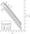
- the ⁇ s 2 values at different core height and width may be determined using a commercial waveguide simulation tool, which utilizes a beam propagation method to determine the waveguide mode field. It can be shown that the propagation loss increases monotonically with both the core height and width in the desired core dimension range. For instance, the loss increases from 0.031dB/cm to 0.524 dB/cm when the core height increases from 10nm to 60nm at fixed width of 3.7 ⁇ m (see FIG. 8A ).
- a important measure to have an accuracy and sensitivity FOG is to minimize the cross-polarization coupling in the Sagnac interferometer. This becomes more important in the PIC FOG since the integrated waveguide can be subject to more material stress and more optical scattering, and the distances between functional components are closer.
- Making waveguide of the FOG PIC "highly" polarization maintaining is crucial to mitigate the cross-polarization coupling.
- the waveguide In order to fabricate a waveguide highly polarization maintaining, the waveguide needs to be designed to be of ultra-high birefringent and ultra-low scattering.
- the noise floor between the front pigtailing point (504) and back pigtailing point (506) is mainly less than -63dB, and accumulated total P x / P o is less than -60 dB.
- the waveguide length between the two pigtailing points is 3.3 cm. Therefore, the H-parameter of the waveguide in the example embodiment is H ⁇ -45 dB/m.
- FIGs. 9A, 9B and 9C show the simulated mode field at a fixed waveguide width and with the waveguide height increasing from FIG. 9A to 9C .
- the mode field is drastically squeezed out into the SiO 2 cladding at 10nm core height in both horizontal and vertical directions. This makes normalized electric field strength at the core/cladding interface, ⁇ s 2 , a very small value, therefore the waveguide has a correspondingly low propagation loss.
- the mode field becomes more concentrated at the Si 3 N 4 core strip in both horizontal and vertical directions (see FIG. 9C ) and results in a larger ⁇ s 2 value and a higher loss waveguide.
- the mode-field change is much slower with waveguide width than that with the height as shown in FIGs. 9D, 9E and 9F .
- the mode field expends in the horizontal direction approximately linearly with the increase of the core width when core has a fixed height, while the mode height has almost no change. In this process, the ⁇ s 2 value increases and almost saturates for greater waveguide widths, so is the propagation as indicated in FIG. 8B .
- the loss at the two corresponding locations are 0.22 and 0.52 dB/cm.
- the loss is more than doubled (136%) from the 0.22dB/cm to 0.52 dB/cm loss.
Landscapes
- Physics & Mathematics (AREA)
- General Physics & Mathematics (AREA)
- Optics & Photonics (AREA)
- Engineering & Computer Science (AREA)
- Electromagnetism (AREA)
- Power Engineering (AREA)
- Radar, Positioning & Navigation (AREA)
- Remote Sensing (AREA)
- Optical Integrated Circuits (AREA)
- Gyroscopes (AREA)
- Optical Couplings Of Light Guides (AREA)
Claims (12)
- Photonische integrierte Schaltung (PIC), umfassend:einen Polarisierer (118), umfassend einen Polarisierer-Wellenleiter und aufweisend einen ersten Polarisiereranschluss und einen zweiten Polarisiereranschluss, wobei der Polarisierer konfiguriert ist, um innerhalb einer Bereichs von Betriebswellenlängen der PIC ein Propagation Extinction Ratio (PER) von mindestens75dB und eine Doppelbrechung von mindestens 0,012 aufzuweisen;eine Quell-Y-Gabelung (114) mit einem Quellbasis-Wellenleiter, der mit dem ersten Polarisiereranschluss gekoppelt ist, einen ersten Verzweigungswellenleiter, der mit einem Quellverbinder gekoppelt ist, der konfiguriert ist, um mit einer Lichtquelle verbunden zu sein, und einen zweiten Quellverzweigungswellenleiter, der mit einem Detektorverbinder gekoppelt ist, der konfiguriert ist, mit einem Photodetektor verbunden zu sein, wobei der Quellbasiswellenleiter und die Verzweigungswellenleiter (i) polarisationserhaltend (PM) und (ii) konfiguriert sind, um einen einzigen Querlichtmodus zu unterstützen; undeine interferometrische Y-Gabelung (116) mit einem interferommetrischen Basiswellenleiter, der mit dem zweiten Polarisiereranschluss gekoppelt ist, einen ersten interferometrischen Verzweigungswellenleiter, der mit einem ersten Faserspulenverbinder gekoppelt ist, der konfiguriert ist, um mit einem ersten Anschluss einer Faserspule verbunden zu sein, und einen zweiten interferometrischen Wellenleiter, der mit einem zweiten Faserspulenverbinder gekoppelt ist, der konfiguriert ist, um mit einem zweiten Anschluss der Faserspule verbunden zu sein,wobei der interferometrische Basiswellenleiter und Verzweigungswellenleiter (i) polarisationserhaltend (PM) sind, (ii) eine vorbestimmte Längendifferenz mit Bezug aufeinander aufweisen und (iii) konfiguriert sind, um einen einzigen Querlichtmodus zu unterstützen, wobei der Polarisierer (118) im Wesentlichen mit der interferometrischen Y-Gabelung (116) ausgefluchtet ist, mit einem einzelnen Moduswellenleiterfilter dazwischen; wobei der Polarisiererwellenleiter drei 180-Grad-Kurven umfasst, die aufeinanderfolgend miteinander gekoppelt sind, um eine m-Form zu bilden;wobei eine Wellenleiterlängendifferenz zwischen dem interferometrischen ersten Verzweigungswellenleiter und dem interferometrischen zweiten Verzweigungswellenleiter grösser als eine Entpolarisiererlänge und des interferometrischen zweiten Verzweigungswellenleiters ist.
- Photonische integrierte Schaltung nach Anspruch 1, wobei ein H-Parameter jedes des Polarisiererwellenleiters, des Basiswellenleiters, des ersten Verzweigungswellenleiters und des zweiten Verzweigungswellenleiters weniger als -40 dB/m ist.
- Photonische integrierte Schaltung nach Anspruch 1, wobei der Polarisiererwellenleiter, der erste Verzweigungswellenleiter und der zweite Verzweigungswellenleiter jeweils einen Si3N4-Kern umfassen, der von SiO2-Verkleidungsmaterial umgeben ist.
- Photonische integrierte Schaltung nach Anspruch 3, wobei der Kern ein Längenverhältnis Breite zu Höhe von mindestens 50 aufweist.
- Photonische integrierte Schaltung nach Anspruch 1, weiter umfassend einen oder mehrere Gräben, die entlang der Wellenleiter der Quell-Y-Gabelung (114), der interferometrischen Y-Gabelung (116) und des Polarisierers (118) geätzt sind, wobei der Graben konfiguriert ist, um Licht abzulenken, das vom Wellenleiter weg von der PIC gestrahlt wird, um zu verhindern, dass Streulicht in die PIC gekoppelt wird.
- Photonische integrierte Schaltung nach Anspruch 1, wobei die Basiswellenleiter und die Verzweigungswellenleiter eine Doppelbrechung von mindestens 0,012 aufweisen.
- Photonische integrierte Schaltung nach Anspruch 1, wobei die Basiswellenleiter und die Verzweigungswellenleiter einen Ausbreitungsverlust von weniger als 0,5 dB/cm aufweisen.
- Photonische integrierte Schaltung nach Anspruch 1, wobei die Basiswellenleiter und die Verzweigungswellenleiter einen dünnen Si3N4-Wellenleiter mit einer Kerndicke umfassen, die grösser als oder gleich wie 10 nm und kleiner als oder gleich wie 100 nm ist, und mit einer Kernbreite, die grösser als oder gleich wie 1 Mikrometer und kleiner als oder gleich wie 10 Mikrometer ist.
- Photonische integrierte Schaltung nach Anspruch 1, wobei der Basiswellenleiter der interferometrischen Y-Gabelung (116) länger als eine Entpolarisierungslänge ist, die mit dem Basiswellenleiter der interferometrischen Y-Gabelung (116) verbunden ist.
- Photonische integrierte Schaltung nach Anspruch 1, wobei die erste Verzweigung, der zweite Verzweigungswellenleiter und der Basiswellenleiter und die Quell-Y-Gabelung (114) jeweils ein Längenverhältnis Breite zu Höhe von mindestens 50 aufweisen.
- Photonische integrierte Schaltung nach Anspruch 1, wobei die erste Verzweigung, der zweite Verzweigungswellenleiter und der Basiswellenleiter der Quell-Y-Gabelung (114) jeweils einen Si3N4-Kern umfassen, der von SiO2-Verkleidungsmaterial umgeben ist.
- Faserkreisel (IFOG), umfassend:eine photonische integrierte Schaltung (PIC) nach einem der Ansprüche 1 bis 11;eine Faserspule (106) mit einem ersten Ende, das mit einem ersten Faserspulenverbinder gekoppelt ist, und einem zweiten Ende, das mit einem zweiten Faserspulenverbinder gekoppelt ist; undeinen Phasenmodulator (108), der in die Abtastfaserspule (106) eingeschlossen ist, die sich nahe an einem Ende der Abtastfaserspule befindet.
Applications Claiming Priority (2)
| Application Number | Priority Date | Filing Date | Title |
|---|---|---|---|
| US201862744505P | 2018-10-11 | 2018-10-11 | |
| PCT/US2019/055849 WO2020077216A1 (en) | 2018-10-11 | 2019-10-11 | Photonic integrated circuits, fiber optic gyroscopes and methods for making the same |
Publications (2)
| Publication Number | Publication Date |
|---|---|
| EP3864373A1 EP3864373A1 (de) | 2021-08-18 |
| EP3864373B1 true EP3864373B1 (de) | 2025-04-23 |
Family
ID=68387426
Family Applications (1)
| Application Number | Title | Priority Date | Filing Date |
|---|---|---|---|
| EP19795412.6A Active EP3864373B1 (de) | 2018-10-11 | 2019-10-11 | Photonische integrierte schaltungen, faseroptische gyroscope und verfahren zu deren herstellung |
Country Status (6)
| Country | Link |
|---|---|
| US (1) | US11415419B2 (de) |
| EP (1) | EP3864373B1 (de) |
| JP (2) | JP2022504470A (de) |
| KR (1) | KR20210084492A (de) |
| CA (1) | CA3115993A1 (de) |
| WO (1) | WO2020077216A1 (de) |
Families Citing this family (21)
| Publication number | Priority date | Publication date | Assignee | Title |
|---|---|---|---|---|
| US11320267B2 (en) | 2017-03-23 | 2022-05-03 | Kvh Industries, Inc. | Integrated optic wavemeter and method for fiber optic gyroscopes scale factor stabilization |
| KR20200060718A (ko) | 2017-09-15 | 2020-06-01 | 케이브이에이치 인더스트리즈, 인코포레이티드 | 광자 집적 회로의 도파관에 광섬유의 자기 정렬 연결을 위한 방법 및 장치 |
| EP3864373B1 (de) | 2018-10-11 | 2025-04-23 | EMCORE Corporation | Photonische integrierte schaltungen, faseroptische gyroscope und verfahren zu deren herstellung |
| FR3087255B1 (fr) * | 2018-10-11 | 2020-10-09 | Ixblue | Interferometre de sagnac a fibre optique compact |
| CA3115836A1 (en) | 2018-10-31 | 2020-05-07 | Kvh Industries, Inc. | Method and apparatus for control and suppression of stray light in a photonic integrated circuit |
| US11353655B2 (en) | 2019-05-22 | 2022-06-07 | Kvh Industries, Inc. | Integrated optical polarizer and method of making same |
| US10921682B1 (en) | 2019-08-16 | 2021-02-16 | Kvh Industries, Inc. | Integrated optical phase modulator and method of making same |
| US11175140B2 (en) * | 2019-09-10 | 2021-11-16 | Honeywell International Inc. | Resonator fiber optic gyroscope with integrated photonics interface |
| TWI719888B (zh) * | 2020-04-17 | 2021-02-21 | 極星光電股份有限公司 | 積體雙翼式光電感測核心晶片 |
| CN115298665A (zh) * | 2020-04-17 | 2022-11-04 | 美商新思科技有限公司 | 使用固定坐标网格的光子集成电路的布局 |
| US11204469B1 (en) | 2020-06-01 | 2021-12-21 | Honeywell International Inc. | Apparatus for high-efficiency fiber-to-chip coupling and mode-conversion to integrated photonics platform |
| US12493000B2 (en) * | 2020-10-29 | 2025-12-09 | University Of Rochester | Photonic integrated circuit and characterization method |
| GB2601117B (en) * | 2020-11-13 | 2023-09-13 | Siloton Ltd | Integrated optical system for spectral domain optical coherence tomography |
| US12352571B2 (en) | 2021-08-11 | 2025-07-08 | Emcore Corporation | In-situ residual intensity noise measurement method and system |
| WO2023211518A2 (en) * | 2021-11-30 | 2023-11-02 | Emcore Corporation | Multi-axis fiber optic gyroscope photonic integrated circuit for inertial measurement units and inertial navigation systems |
| CN114397729B (zh) * | 2021-12-06 | 2024-05-28 | 广东奥斯诺工业有限公司 | 基于连续曲率弯曲波导起偏器的SiN集成光学芯片 |
| US12442996B2 (en) * | 2022-07-12 | 2025-10-14 | Globalfoundries U.S. Inc. | Scattering light-based monitor for photonic integrated circuit, monitoring system and monitoring method |
| US11656080B1 (en) | 2022-08-23 | 2023-05-23 | Anello Photonics, Inc. | Silicon nitride waveguide based integrated photonics front-end chip for optical gyroscope |
| CN116558495A (zh) * | 2023-05-15 | 2023-08-08 | 赛丽科技(苏州)有限公司 | 集成干涉光学陀螺仪、组件、系统和计算旋速信息的方法 |
| CN117490676B (zh) * | 2023-12-28 | 2024-04-02 | 广东奥斯诺工业有限公司 | 单片集成薄膜铌酸锂光子驱动芯片及光纤陀螺 |
| US20260079042A1 (en) * | 2024-09-13 | 2026-03-19 | Torc Robotics, Inc. | System for fiber-optic gyroscope in an autonomous vehicle |
Family Cites Families (103)
| Publication number | Priority date | Publication date | Assignee | Title |
|---|---|---|---|---|
| US4678267A (en) | 1977-11-18 | 1987-07-07 | The United States Of America As Represented By The Secretary Of The Navy | Parabolic optical waveguide horns and design thereof |
| US4420259A (en) | 1981-10-23 | 1983-12-13 | The United States Of America As Represented By The Secretary Of The Navy | Double coupled dual input rate sensor |
| US4890922A (en) | 1987-02-20 | 1990-01-02 | Litton Systems, Inc. | Thermally compensated reference interferometer and method |
| GB2201256B (en) | 1987-02-20 | 1990-11-14 | Litton Systems Inc | Devices for controlling the frequency of an optical signal output from an optical signal source |
| US4842358A (en) | 1987-02-20 | 1989-06-27 | Litton Systems, Inc. | Apparatus and method for optical signal source stabilization |
| GB8719716D0 (en) | 1987-08-20 | 1987-09-30 | Whitford Plastics Ltd | Thermal spraying of stainless steel |
| US4915503A (en) | 1987-09-01 | 1990-04-10 | Litton Systems, Inc. | Fiber optic gyroscope with improved bias stability and repeatability and method |
| JPH0743264B2 (ja) * | 1988-04-19 | 1995-05-15 | リットン・システムズ・インコーポレーテッド | 統合されたオプチック干渉計的ファイバジャイロスコープモジュール |
| US4938594A (en) | 1988-10-14 | 1990-07-03 | Litton Systems, Inc. | Asymmetric |
| EP0389172B1 (de) * | 1989-03-23 | 1995-10-18 | AT&T Corp. | Bauelement für die adiabatische Veränderung der Polarisation |
| US5223911A (en) | 1989-03-27 | 1993-06-29 | United Technologies Corporation | Single-polarization, integrated optical components for optical gyroscopes |
| US5037205A (en) * | 1989-04-19 | 1991-08-06 | Litton Systems, Inc. | Integrated optic interferometric fiber gyroscope module and method |
| US4969742A (en) | 1989-06-27 | 1990-11-13 | The Boeing Company | Integrated optic wavemeter |
| US5393371A (en) | 1989-12-18 | 1995-02-28 | Litton Systems, Inc. | Integrated optics chips and laser ablation methods for attachment of optical fibers thereto for LiNbO3 substrates |
| US5321503A (en) | 1990-06-04 | 1994-06-14 | The United States Of America As Represented By The Secretary Of The Navy | Closed loop, depolarized interferometric fiber optic (IFOG) gyroscope with self adjusting serrodyne phase nulling |
| DE4027024A1 (de) | 1990-08-27 | 1992-03-05 | Standard Elektrik Lorenz Ag | Faserkreisel |
| US5365338A (en) | 1991-05-28 | 1994-11-15 | The United States Of America As Represented By The Secretary Of The Navy | Wavelength sensor for fiber optic gyroscope |
| JPH05224045A (ja) * | 1991-08-07 | 1993-09-03 | Litton Syst Inc | ニオブ酸リチウム基板用集積光学チップ及びそれへの光ファイバーの取付けのためのレーザー融除方法 |
| EP0631159A1 (de) | 1993-06-18 | 1994-12-28 | Siemens Aktiengesellschaft | Anordnung zur optischen Kopplung eines planaren optischen Wellenleiters und einer optischen Faser und Verfahren zur Herstellung eines für eine solche Anordnung geeigneten planaren Wellenleiters |
| US5436992A (en) | 1994-10-18 | 1995-07-25 | National Science Council | Lithium niobate optical TE-TM mode splitter |
| US5537671A (en) | 1995-02-10 | 1996-07-16 | The Board Of Trustees Of The Leland Stanford Junior University | Technique of reducing the Kerr effect and extending the dynamic range in a brillouin fiber optic gyroscope |
| JPH08226822A (ja) | 1995-02-22 | 1996-09-03 | Tokimec Inc | 光ファイバジャイロ及び光集積回路 |
| US5627644A (en) | 1995-06-07 | 1997-05-06 | Sanders; Glen A. | Kerr effect compensation by optical power balancing in interferometric fiber optic gyroscopes |
| JP3813220B2 (ja) | 1995-12-14 | 2006-08-23 | 株式会社フジクラ | 開放ピース付き光ファイバ接続器および作業治具 |
| WO1997011396A1 (en) | 1995-09-20 | 1997-03-27 | Philips Electronics N.V. | Integrated optical circuit comprising a polarization convertor |
| US5600745A (en) | 1996-02-08 | 1997-02-04 | Industrial Technology Research Institute | Method of automatically coupling between a fiber and an optical waveguide |
| US5729641A (en) | 1996-05-30 | 1998-03-17 | Sdl, Inc. | Optical device employing edge-coupled waveguide geometry |
| IN190212B (de) | 1996-07-23 | 2003-07-05 | Samsung Electronics Co Ltd | |
| US5982961A (en) | 1997-01-21 | 1999-11-09 | Molecular Optoelectronics Corporation | Organic crystal compound optical waveguide and methods for its fabrication |
| EP0883000A1 (de) | 1997-06-02 | 1998-12-09 | Akzo Nobel N.V. | Planare optische Wellenleiterstruktur mit einem Bereich zur Erfassung von Streustrahlung und Verfahren zur Herstellung dieser Struktur |
| US5949930A (en) | 1997-07-23 | 1999-09-07 | Litton Systems, Inc. | Apparatus and method for scale factor stabilization in interferometric fiber optic rotation sensors |
| GB2329482B (en) | 1997-09-23 | 1999-08-11 | Bookham Technology Ltd | An optical circuit |
| US6114088A (en) | 1999-01-15 | 2000-09-05 | 3M Innovative Properties Company | Thermal transfer element for forming multilayer devices |
| US6108086A (en) | 1999-03-04 | 2000-08-22 | Litton Systems, Inc. | System and method of stabilizing the scale factor shift in fiber optic gyroscopes using a spectral monitor array |
| US6360038B1 (en) | 1999-05-12 | 2002-03-19 | Sabeus Photonics, Inc. | Wavelength-selective optical fiber components using cladding-mode assisted coupling |
| US8121874B1 (en) | 1999-05-27 | 2012-02-21 | Accenture Global Services Limited | Phase delivery of components of a system required for implementation technology |
| NO324337B1 (no) | 1999-09-15 | 2007-09-24 | Optoplan As | Anordning for maling av optiske bolgelengder |
| US6996316B2 (en) | 1999-09-20 | 2006-02-07 | Cidra Corporation | Large diameter D-shaped optical waveguide and coupler |
| US6293688B1 (en) | 1999-11-12 | 2001-09-25 | Sparkolor Corporation | Tapered optical waveguide coupler |
| BR0109069A (pt) | 2000-03-08 | 2004-12-07 | Ntu Ventures Pte Ltd | Processo para fabricar um circuito integrado fotÈnico |
| US6760520B1 (en) | 2000-05-09 | 2004-07-06 | Teralux Corporation | System and method for passively aligning and coupling optical devices |
| US6445455B1 (en) | 2000-05-23 | 2002-09-03 | Northrop Grumman Corporation | Phase and intensity modulated IFOG |
| US6727745B2 (en) | 2000-08-23 | 2004-04-27 | Intersil Americas Inc. | Integrated circuit with current sense circuit and associated methods |
| US20030044118A1 (en) | 2000-10-20 | 2003-03-06 | Phosistor Technologies, Inc. | Integrated planar composite coupling structures for bi-directional light beam transformation between a small mode size waveguide and a large mode size waveguide |
| US6822743B2 (en) | 2001-03-07 | 2004-11-23 | Paul Trinh | Integrated-optic channel monitoring |
| KR100908623B1 (ko) | 2001-10-30 | 2009-07-21 | 호야 코포레이션 유에스에이 | 광출력의 횡단 전달을 이용하는 광학적 접합 장치 및 방법 |
| US6905904B2 (en) | 2002-06-24 | 2005-06-14 | Dow Corning Corporation | Planar optical waveguide assembly and method of preparing same |
| US20050021348A1 (en) | 2002-07-19 | 2005-01-27 | Claribel Chan | Business solution management (BSM) |
| EP1396741A1 (de) | 2002-09-04 | 2004-03-10 | Avanex Corporation | Streulichtunterdrückungsstrukturen mit einem Wellenleiter und tief unter einem Winkel geätzten und mit einem Absorbermaterial gefüllten Gräben |
| US7076135B2 (en) | 2002-09-20 | 2006-07-11 | Nippon Telegraph And Telephone Corporation | Optical module and manufacturing method therefor |
| US7061610B2 (en) | 2003-02-14 | 2006-06-13 | Technology Asset Trust | Photonic integrated circuit based planar wavelength meter |
| EP1447690A1 (de) | 2003-02-14 | 2004-08-18 | Avanex Corporation | Streulichtablenker |
| USPP15134P2 (en) | 2003-02-21 | 2004-09-07 | Bundesanstalt Fur Zuchtungsforschung An Kulturpflanzen | Apple tree named ‘Rebella’ |
| US6920257B1 (en) | 2003-03-24 | 2005-07-19 | Inplane Photonics, Inc. | Resonator cavity for optical isolation |
| US7171085B2 (en) | 2003-07-29 | 2007-01-30 | Jds Uniphase Corporation | Polarization compensated optical tap |
| US7224878B1 (en) | 2004-11-12 | 2007-05-29 | Northwestern University | BaTiO3 thin film waveguides and related modulator devices |
| US7085441B1 (en) | 2005-03-04 | 2006-08-01 | Northrop Grumman Corporation | Fiber-optic gyroscope with depolarizer using integrated optic waveguide |
| JP4658658B2 (ja) | 2005-03-29 | 2011-03-23 | 住友大阪セメント株式会社 | 光変調器 |
| US7943229B2 (en) | 2005-05-06 | 2011-05-17 | Hoya Corporation Usa | Suppression of stray light propagation in a substrate |
| JP2007272121A (ja) | 2006-03-31 | 2007-10-18 | Sumitomo Osaka Cement Co Ltd | 光素子 |
| US7515271B2 (en) | 2006-04-03 | 2009-04-07 | Honeywell International Inc. | Wavelength calibration in a fiber optic gyroscope |
| JP4785925B2 (ja) | 2006-08-16 | 2011-10-05 | 富士通オプティカルコンポーネンツ株式会社 | 導波路型偏光子および光導波路デバイス |
| US7853108B2 (en) * | 2006-12-29 | 2010-12-14 | Massachusetts Institute Of Technology | Fabrication-tolerant waveguides and resonators |
| DE102007019812B4 (de) | 2007-04-26 | 2021-08-26 | Carl Zeiss Meditec Ag | Laserchirurgische Vorrichtung zur Augenbehandlung |
| US20080291459A1 (en) | 2007-05-22 | 2008-11-27 | Litton Systems, Inc. | Fiber optic gyroscope with integrated light source |
| JP4886627B2 (ja) | 2007-07-31 | 2012-02-29 | 株式会社東芝 | 光結合デバイス |
| IL205351A (en) | 2009-04-28 | 2017-05-29 | Univ Leland Stanford Junior | Optical gyroscope driven by a laser having an indelible source coherence length |
| CN102858909A (zh) | 2009-11-06 | 2013-01-02 | 辐射测定和成像股份有限公司 | 用于辐射存储的核壳型纳米磷光体和方法 |
| CN103858035A (zh) | 2011-10-28 | 2014-06-11 | Hoya美国公司 | 波导衬底上用于衰减光源的光波导分路器 |
| FR2986622B1 (fr) | 2012-02-07 | 2014-03-07 | Ixblue | Circuit optique integre a rainure excentree |
| JP5949900B2 (ja) | 2012-03-19 | 2016-07-13 | 富士通株式会社 | 偏光度低減装置、光源装置、光増幅装置およびラマン増幅用励起光源装置 |
| JP2013255086A (ja) | 2012-06-07 | 2013-12-19 | Hitachi Ltd | マルチレートponシステム、その局側及び宅内光回線終端装置 |
| JP5288028B2 (ja) | 2012-07-02 | 2013-09-11 | 住友大阪セメント株式会社 | 光導波路素子 |
| US9383900B2 (en) | 2012-09-12 | 2016-07-05 | International Business Machines Corporation | Enabling real-time operational environment conformity to an enterprise model |
| US20150212271A1 (en) | 2012-12-11 | 2015-07-30 | Acacia Communications Inc. | Optical waveguide terminators with doped waveguides |
| US9383512B2 (en) | 2012-12-31 | 2016-07-05 | Infinera Corporation | Light absorption and scattering devices in a photonic integrated circuit that minimize optical feedback and noise |
| US9746612B2 (en) | 2013-04-22 | 2017-08-29 | Cornell University | Fiber-waveguide evanescent coupler |
| US9683928B2 (en) | 2013-06-23 | 2017-06-20 | Eric Swanson | Integrated optical system and components utilizing tunable optical sources and coherent detection and phased array for imaging, ranging, sensing, communications and other applications |
| US9134498B2 (en) | 2013-07-18 | 2015-09-15 | Cisco Technology, Inc. | Coupling system for optical fibers and optical waveguides |
| US9365462B2 (en) | 2013-07-23 | 2016-06-14 | Compass Minerals Manitoba, Inc. | Phosphate magnesium zinc fertilizer |
| TWI635330B (zh) | 2014-01-14 | 2018-09-11 | 美國麻省理工學院 | 用於形成積體電路之方法及相關積體電路 |
| US9690045B2 (en) | 2014-03-31 | 2017-06-27 | Huawei Technologies Co., Ltd. | Apparatus and method for a waveguide polarizer comprising a series of bends |
| JP6137023B2 (ja) | 2014-03-31 | 2017-05-31 | 住友大阪セメント株式会社 | 光導波路素子 |
| US9563758B2 (en) | 2014-05-12 | 2017-02-07 | International Business Machines Corporation | Increasing security of a device and/or system via questioning about a characteristic of the device and/or system |
| DK3167318T3 (da) | 2014-07-08 | 2022-06-13 | Univ Gent | Polarisationsuafhængig behandling ved integreret fotonik |
| WO2016010528A1 (en) | 2014-07-15 | 2016-01-21 | Nokia Technologies Oy | Ultra-compact wavelength meter |
| EP3180643A1 (de) | 2014-08-15 | 2017-06-21 | Corning Optical Communications LLC | Verfahren zur kopplung von wellenleitern mit verschiedenen modenfelddurchmessern und entsprechende vorrichtungen, komponenten und systeme |
| US9746609B2 (en) | 2015-06-30 | 2017-08-29 | Elenion Technologies, Llc | Integrated on-chip polarizer |
| US9739938B2 (en) | 2015-12-09 | 2017-08-22 | Elenion Technologies, Llc | Shielded photonic integrated circuit |
| US9810840B2 (en) | 2016-01-06 | 2017-11-07 | Elenion Technologies Llc | Integrated on-chip polarizer |
| US10545290B2 (en) | 2016-01-18 | 2020-01-28 | Corning Incorporated | Polymer clad fiber for evanescent coupling |
| JP6872329B2 (ja) | 2016-09-07 | 2021-05-19 | 富士通株式会社 | 光ファイバ搭載光集積回路装置 |
| US10126500B2 (en) | 2016-11-01 | 2018-11-13 | Purdue Research Foundation | Optical coupler having exposed subwavelength gratings for coupling electromagnetic field |
| EP3593087B1 (de) * | 2017-03-09 | 2020-12-02 | KVH Industries, Inc. | Photonische integrierte schaltung für einen faseroptischen interferenzkreisel (ifog) |
| US11320267B2 (en) | 2017-03-23 | 2022-05-03 | Kvh Industries, Inc. | Integrated optic wavemeter and method for fiber optic gyroscopes scale factor stabilization |
| GB2566314B (en) | 2017-09-08 | 2020-07-29 | Exalos Ag | Depolarisers |
| KR20200060718A (ko) | 2017-09-15 | 2020-06-01 | 케이브이에이치 인더스트리즈, 인코포레이티드 | 광자 집적 회로의 도파관에 광섬유의 자기 정렬 연결을 위한 방법 및 장치 |
| CN107843957A (zh) | 2017-11-13 | 2018-03-27 | 上海理工大学 | 氮化硅‑铌酸锂异质集成波导器件结构及制备方法 |
| EP3864373B1 (de) | 2018-10-11 | 2025-04-23 | EMCORE Corporation | Photonische integrierte schaltungen, faseroptische gyroscope und verfahren zu deren herstellung |
| CA3115836A1 (en) | 2018-10-31 | 2020-05-07 | Kvh Industries, Inc. | Method and apparatus for control and suppression of stray light in a photonic integrated circuit |
| US11353655B2 (en) | 2019-05-22 | 2022-06-07 | Kvh Industries, Inc. | Integrated optical polarizer and method of making same |
| US10921682B1 (en) | 2019-08-16 | 2021-02-16 | Kvh Industries, Inc. | Integrated optical phase modulator and method of making same |
| US20210240050A1 (en) | 2020-01-30 | 2021-08-05 | Kvh Industries, Inc. | Integrated Modulator Structure for In-situ Power Balancing in Photonic Fiber Optic Gyroscopes |
-
2019
- 2019-10-11 EP EP19795412.6A patent/EP3864373B1/de active Active
- 2019-10-11 JP JP2021519142A patent/JP2022504470A/ja active Pending
- 2019-10-11 CA CA3115993A patent/CA3115993A1/en active Pending
- 2019-10-11 KR KR1020217014099A patent/KR20210084492A/ko active Pending
- 2019-10-11 US US16/599,379 patent/US11415419B2/en active Active
- 2019-10-11 WO PCT/US2019/055849 patent/WO2020077216A1/en not_active Ceased
-
2024
- 2024-12-02 JP JP2024209470A patent/JP2025029068A/ja active Pending
Also Published As
| Publication number | Publication date |
|---|---|
| US20200116489A1 (en) | 2020-04-16 |
| EP3864373A1 (de) | 2021-08-18 |
| KR20210084492A (ko) | 2021-07-07 |
| WO2020077216A1 (en) | 2020-04-16 |
| JP2025029068A (ja) | 2025-03-05 |
| US11415419B2 (en) | 2022-08-16 |
| JP2022504470A (ja) | 2022-01-13 |
| CA3115993A1 (en) | 2020-04-16 |
Similar Documents
| Publication | Publication Date | Title |
|---|---|---|
| EP3864373B1 (de) | Photonische integrierte schaltungen, faseroptische gyroscope und verfahren zu deren herstellung | |
| US11947159B2 (en) | Interferometric fibre optic gyroscopes using hollow core optical fibre and methods thereof | |
| EP3593087B1 (de) | Photonische integrierte schaltung für einen faseroptischen interferenzkreisel (ifog) | |
| US11353655B2 (en) | Integrated optical polarizer and method of making same | |
| Wang et al. | Silicon photonics multi-function integrated optical circuit for miniaturized fiber optic gyroscope | |
| JP5474282B2 (ja) | 集積光学回転センサおよび回転レートを検出する方法 | |
| JPH04265816A (ja) | 集積光学ジャイロスコープセンサ | |
| CN114527538B (zh) | 一种具有模式选择结构的铌酸锂薄膜芯片 | |
| CN102128621A (zh) | 用于多维矢量测量的干涉式光纤陀螺仪 | |
| EP1111413B1 (de) | Multifunktioneller integriert-optischer Chip mit verbessertem Polarisationsauslöschungsverhältnis | |
| Guo et al. | Three-axis interferometric fiber optic gyroscope with silica integrated coupler chip | |
| JP2009288246A (ja) | 高信頼性低損失の中空コアファイバ共振器 | |
| JP3804451B2 (ja) | 一体化光学チップでのクロスカップリング抑制用のトレンチ構成体 | |
| US7003186B2 (en) | Waveguide-based optical interferometer | |
| CN109579814B (zh) | 一种光纤陀螺仪 | |
| CN117433500B (zh) | 基于光子芯片的偏振模式复用双倍光程的光纤陀螺 | |
| US7802928B2 (en) | System and method for fiber based resonator coupling | |
| EP0563279A1 (de) | Optischer faserkreisel. | |
| US11353656B1 (en) | On-chip polarization control | |
| JPH01299412A (ja) | 回転角速度センサ | |
| Schroder et al. | Progress in fiber gyro development for attitude and heading reference systems | |
| HK40017341B (en) | Photonic integrated circuit for an interference fiber optic gyroscope (ifog) |
Legal Events
| Date | Code | Title | Description |
|---|---|---|---|
| STAA | Information on the status of an ep patent application or granted ep patent |
Free format text: STATUS: UNKNOWN |
|
| STAA | Information on the status of an ep patent application or granted ep patent |
Free format text: STATUS: THE INTERNATIONAL PUBLICATION HAS BEEN MADE |
|
| PUAI | Public reference made under article 153(3) epc to a published international application that has entered the european phase |
Free format text: ORIGINAL CODE: 0009012 |
|
| STAA | Information on the status of an ep patent application or granted ep patent |
Free format text: STATUS: REQUEST FOR EXAMINATION WAS MADE |
|
| 17P | Request for examination filed |
Effective date: 20210511 |
|
| AK | Designated contracting states |
Kind code of ref document: A1 Designated state(s): AL AT BE BG CH CY CZ DE DK EE ES FI FR GB GR HR HU IE IS IT LI LT LU LV MC MK MT NL NO PL PT RO RS SE SI SK SM TR |
|
| DAV | Request for validation of the european patent (deleted) | ||
| DAX | Request for extension of the european patent (deleted) | ||
| REG | Reference to a national code |
Ref country code: HK Ref legal event code: DE Ref document number: 40053014 Country of ref document: HK |
|
| STAA | Information on the status of an ep patent application or granted ep patent |
Free format text: STATUS: EXAMINATION IS IN PROGRESS |
|
| 17Q | First examination report despatched |
Effective date: 20230227 |
|
| GRAP | Despatch of communication of intention to grant a patent |
Free format text: ORIGINAL CODE: EPIDOSNIGR1 |
|
| STAA | Information on the status of an ep patent application or granted ep patent |
Free format text: STATUS: GRANT OF PATENT IS INTENDED |
|
| INTG | Intention to grant announced |
Effective date: 20241114 |
|
| RAP1 | Party data changed (applicant data changed or rights of an application transferred) |
Owner name: EMCORE CORPORATION |
|
| GRAS | Grant fee paid |
Free format text: ORIGINAL CODE: EPIDOSNIGR3 |
|
| RAP3 | Party data changed (applicant data changed or rights of an application transferred) |
Owner name: EMCORE CORPORATION |
|
| GRAA | (expected) grant |
Free format text: ORIGINAL CODE: 0009210 |
|
| STAA | Information on the status of an ep patent application or granted ep patent |
Free format text: STATUS: THE PATENT HAS BEEN GRANTED |
|
| AK | Designated contracting states |
Kind code of ref document: B1 Designated state(s): AL AT BE BG CH CY CZ DE DK EE ES FI FR GB GR HR HU IE IS IT LI LT LU LV MC MK MT NL NO PL PT RO RS SE SI SK SM TR |
|
| REG | Reference to a national code |
Ref country code: GB Ref legal event code: FG4D |
|
| REG | Reference to a national code |
Ref country code: CH Ref legal event code: EP |
|
| REG | Reference to a national code |
Ref country code: DE Ref legal event code: R096 Ref document number: 602019069049 Country of ref document: DE |
|
| REG | Reference to a national code |
Ref country code: IE Ref legal event code: FG4D |
|
| REG | Reference to a national code |
Ref country code: NL Ref legal event code: MP Effective date: 20250423 |
|
| PG25 | Lapsed in a contracting state [announced via postgrant information from national office to epo] |
Ref country code: NL Free format text: LAPSE BECAUSE OF FAILURE TO SUBMIT A TRANSLATION OF THE DESCRIPTION OR TO PAY THE FEE WITHIN THE PRESCRIBED TIME-LIMIT Effective date: 20250423 |
|
| REG | Reference to a national code |
Ref country code: AT Ref legal event code: MK05 Ref document number: 1788126 Country of ref document: AT Kind code of ref document: T Effective date: 20250423 |
|
| PG25 | Lapsed in a contracting state [announced via postgrant information from national office to epo] |
Ref country code: PT Free format text: LAPSE BECAUSE OF FAILURE TO SUBMIT A TRANSLATION OF THE DESCRIPTION OR TO PAY THE FEE WITHIN THE PRESCRIBED TIME-LIMIT Effective date: 20250825 Ref country code: ES Free format text: LAPSE BECAUSE OF FAILURE TO SUBMIT A TRANSLATION OF THE DESCRIPTION OR TO PAY THE FEE WITHIN THE PRESCRIBED TIME-LIMIT Effective date: 20250423 Ref country code: FI Free format text: LAPSE BECAUSE OF FAILURE TO SUBMIT A TRANSLATION OF THE DESCRIPTION OR TO PAY THE FEE WITHIN THE PRESCRIBED TIME-LIMIT Effective date: 20250423 |
|
| REG | Reference to a national code |
Ref country code: LT Ref legal event code: MG9D |
|
| PG25 | Lapsed in a contracting state [announced via postgrant information from national office to epo] |
Ref country code: NO Free format text: LAPSE BECAUSE OF FAILURE TO SUBMIT A TRANSLATION OF THE DESCRIPTION OR TO PAY THE FEE WITHIN THE PRESCRIBED TIME-LIMIT Effective date: 20250723 Ref country code: GR Free format text: LAPSE BECAUSE OF FAILURE TO SUBMIT A TRANSLATION OF THE DESCRIPTION OR TO PAY THE FEE WITHIN THE PRESCRIBED TIME-LIMIT Effective date: 20250724 |
|
| PG25 | Lapsed in a contracting state [announced via postgrant information from national office to epo] |
Ref country code: PL Free format text: LAPSE BECAUSE OF FAILURE TO SUBMIT A TRANSLATION OF THE DESCRIPTION OR TO PAY THE FEE WITHIN THE PRESCRIBED TIME-LIMIT Effective date: 20250423 |
|
| PG25 | Lapsed in a contracting state [announced via postgrant information from national office to epo] |
Ref country code: BG Free format text: LAPSE BECAUSE OF FAILURE TO SUBMIT A TRANSLATION OF THE DESCRIPTION OR TO PAY THE FEE WITHIN THE PRESCRIBED TIME-LIMIT Effective date: 20250423 |
|
| PG25 | Lapsed in a contracting state [announced via postgrant information from national office to epo] |
Ref country code: HR Free format text: LAPSE BECAUSE OF FAILURE TO SUBMIT A TRANSLATION OF THE DESCRIPTION OR TO PAY THE FEE WITHIN THE PRESCRIBED TIME-LIMIT Effective date: 20250423 |
|
| PG25 | Lapsed in a contracting state [announced via postgrant information from national office to epo] |
Ref country code: AT Free format text: LAPSE BECAUSE OF FAILURE TO SUBMIT A TRANSLATION OF THE DESCRIPTION OR TO PAY THE FEE WITHIN THE PRESCRIBED TIME-LIMIT Effective date: 20250423 |
|
| PG25 | Lapsed in a contracting state [announced via postgrant information from national office to epo] |
Ref country code: RS Free format text: LAPSE BECAUSE OF FAILURE TO SUBMIT A TRANSLATION OF THE DESCRIPTION OR TO PAY THE FEE WITHIN THE PRESCRIBED TIME-LIMIT Effective date: 20250723 |
|
| PG25 | Lapsed in a contracting state [announced via postgrant information from national office to epo] |
Ref country code: IS Free format text: LAPSE BECAUSE OF FAILURE TO SUBMIT A TRANSLATION OF THE DESCRIPTION OR TO PAY THE FEE WITHIN THE PRESCRIBED TIME-LIMIT Effective date: 20250823 |
|
| PG25 | Lapsed in a contracting state [announced via postgrant information from national office to epo] |
Ref country code: LV Free format text: LAPSE BECAUSE OF FAILURE TO SUBMIT A TRANSLATION OF THE DESCRIPTION OR TO PAY THE FEE WITHIN THE PRESCRIBED TIME-LIMIT Effective date: 20250423 |
|
| PGFP | Annual fee paid to national office [announced via postgrant information from national office to epo] |
Ref country code: DE Payment date: 20250923 Year of fee payment: 7 |
|
| PGFP | Annual fee paid to national office [announced via postgrant information from national office to epo] |
Ref country code: GB Payment date: 20251022 Year of fee payment: 7 |
|
| PG25 | Lapsed in a contracting state [announced via postgrant information from national office to epo] |
Ref country code: DK Free format text: LAPSE BECAUSE OF FAILURE TO SUBMIT A TRANSLATION OF THE DESCRIPTION OR TO PAY THE FEE WITHIN THE PRESCRIBED TIME-LIMIT Effective date: 20250423 Ref country code: SM Free format text: LAPSE BECAUSE OF FAILURE TO SUBMIT A TRANSLATION OF THE DESCRIPTION OR TO PAY THE FEE WITHIN THE PRESCRIBED TIME-LIMIT Effective date: 20250423 |
|
| PGFP | Annual fee paid to national office [announced via postgrant information from national office to epo] |
Ref country code: FR Payment date: 20251030 Year of fee payment: 7 |
|
| PG25 | Lapsed in a contracting state [announced via postgrant information from national office to epo] |
Ref country code: CZ Free format text: LAPSE BECAUSE OF FAILURE TO SUBMIT A TRANSLATION OF THE DESCRIPTION OR TO PAY THE FEE WITHIN THE PRESCRIBED TIME-LIMIT Effective date: 20250423 |
|
| PG25 | Lapsed in a contracting state [announced via postgrant information from national office to epo] |
Ref country code: EE Free format text: LAPSE BECAUSE OF FAILURE TO SUBMIT A TRANSLATION OF THE DESCRIPTION OR TO PAY THE FEE WITHIN THE PRESCRIBED TIME-LIMIT Effective date: 20250423 |
|
| REG | Reference to a national code |
Ref country code: DE Ref legal event code: R097 Ref document number: 602019069049 Country of ref document: DE |
|
| PG25 | Lapsed in a contracting state [announced via postgrant information from national office to epo] |
Ref country code: RO Free format text: LAPSE BECAUSE OF FAILURE TO SUBMIT A TRANSLATION OF THE DESCRIPTION OR TO PAY THE FEE WITHIN THE PRESCRIBED TIME-LIMIT Effective date: 20250423 Ref country code: SK Free format text: LAPSE BECAUSE OF FAILURE TO SUBMIT A TRANSLATION OF THE DESCRIPTION OR TO PAY THE FEE WITHIN THE PRESCRIBED TIME-LIMIT Effective date: 20250423 |
|
| PG25 | Lapsed in a contracting state [announced via postgrant information from national office to epo] |
Ref country code: IT Free format text: LAPSE BECAUSE OF FAILURE TO SUBMIT A TRANSLATION OF THE DESCRIPTION OR TO PAY THE FEE WITHIN THE PRESCRIBED TIME-LIMIT Effective date: 20250423 |
|
| PLBE | No opposition filed within time limit |
Free format text: ORIGINAL CODE: 0009261 |
|
| STAA | Information on the status of an ep patent application or granted ep patent |
Free format text: STATUS: NO OPPOSITION FILED WITHIN TIME LIMIT |
|
| REG | Reference to a national code |
Ref country code: CH Ref legal event code: L10 Free format text: ST27 STATUS EVENT CODE: U-0-0-L10-L00 (AS PROVIDED BY THE NATIONAL OFFICE) Effective date: 20260304 |
|
| 26N | No opposition filed |
Effective date: 20260126 |