EP3864389B1 - Outil et procede de mesure d'une force sur l'outil - Google Patents
Outil et procede de mesure d'une force sur l'outil Download PDFInfo
- Publication number
- EP3864389B1 EP3864389B1 EP19779520.6A EP19779520A EP3864389B1 EP 3864389 B1 EP3864389 B1 EP 3864389B1 EP 19779520 A EP19779520 A EP 19779520A EP 3864389 B1 EP3864389 B1 EP 3864389B1
- Authority
- EP
- European Patent Office
- Prior art keywords
- tool
- force
- force sensor
- contact surface
- recess
- Prior art date
- Legal status (The legal status is an assumption and is not a legal conclusion. Google has not performed a legal analysis and makes no representation as to the accuracy of the status listed.)
- Active
Links
Images



Classifications
-
- G—PHYSICS
- G01—MEASURING; TESTING
- G01L—MEASURING FORCE, STRESS, TORQUE, WORK, MECHANICAL POWER, MECHANICAL EFFICIENCY, OR FLUID PRESSURE
- G01L5/00—Apparatus for, or methods of, measuring force, work, mechanical power, or torque, specially adapted for specific purposes
- G01L5/0061—Force sensors associated with industrial machines or actuators
- G01L5/0076—Force sensors associated with manufacturing machines
-
- B—PERFORMING OPERATIONS; TRANSPORTING
- B23—MACHINE TOOLS; METAL-WORKING NOT OTHERWISE PROVIDED FOR
- B23B—TURNING; BORING
- B23B25/00—Accessories or auxiliary equipment for turning-machines
- B23B25/06—Measuring, gauging, or adjusting equipment on turning-machines for setting-on, feeding, controlling, or monitoring the cutting tools or work
-
- B—PERFORMING OPERATIONS; TRANSPORTING
- B23—MACHINE TOOLS; METAL-WORKING NOT OTHERWISE PROVIDED FOR
- B23Q—DETAILS, COMPONENTS, OR ACCESSORIES FOR MACHINE TOOLS, e.g. ARRANGEMENTS FOR COPYING OR CONTROLLING; MACHINE TOOLS IN GENERAL CHARACTERISED BY THE CONSTRUCTION OF PARTICULAR DETAILS OR COMPONENTS; COMBINATIONS OR ASSOCIATIONS OF METAL-WORKING MACHINES, NOT DIRECTED TO A PARTICULAR RESULT
- B23Q17/00—Arrangements for observing, indicating or measuring on machine tools
- B23Q17/09—Arrangements for observing, indicating or measuring on machine tools for indicating or measuring cutting pressure or for determining cutting-tool condition, e.g. cutting ability, load on tool
- B23Q17/0952—Arrangements for observing, indicating or measuring on machine tools for indicating or measuring cutting pressure or for determining cutting-tool condition, e.g. cutting ability, load on tool during machining
- B23Q17/0966—Arrangements for observing, indicating or measuring on machine tools for indicating or measuring cutting pressure or for determining cutting-tool condition, e.g. cutting ability, load on tool during machining by measuring a force on parts of the machine other than a motor
-
- G—PHYSICS
- G01—MEASURING; TESTING
- G01L—MEASURING FORCE, STRESS, TORQUE, WORK, MECHANICAL POWER, MECHANICAL EFFICIENCY, OR FLUID PRESSURE
- G01L5/00—Apparatus for, or methods of, measuring force, work, mechanical power, or torque, specially adapted for specific purposes
- G01L5/16—Apparatus for, or methods of, measuring force, work, mechanical power, or torque, specially adapted for specific purposes for measuring several components of force
- G01L5/167—Apparatus for, or methods of, measuring force, work, mechanical power, or torque, specially adapted for specific purposes for measuring several components of force using piezoelectric means
-
- B—PERFORMING OPERATIONS; TRANSPORTING
- B23—MACHINE TOOLS; METAL-WORKING NOT OTHERWISE PROVIDED FOR
- B23Q—DETAILS, COMPONENTS, OR ACCESSORIES FOR MACHINE TOOLS, e.g. ARRANGEMENTS FOR COPYING OR CONTROLLING; MACHINE TOOLS IN GENERAL CHARACTERISED BY THE CONSTRUCTION OF PARTICULAR DETAILS OR COMPONENTS; COMBINATIONS OR ASSOCIATIONS OF METAL-WORKING MACHINES, NOT DIRECTED TO A PARTICULAR RESULT
- B23Q2717/00—Arrangements for indicating or measuring
- B23Q2717/003—Arrangements for indicating or measuring in lathes
Definitions
- the invention relates to a tool with a tool shaft that is accommodated in a tool receptacle of a tool holder. Furthermore, the invention relates to a force sensor that measures a tool force. In addition, the invention relates to a method for measuring a tool force with such a tool and such a force sensor.
- tool forces are usually multidimensional.
- the cutting tool is subjected to both the cutting force exerted by the workpiece on the cutting tool and a feed force.
- Dynamometers can be used to measure such tool forces. However, their large dimensions are a disadvantage, meaning that dynamometers often cause interference in the machine room and cannot be installed anywhere in a machine tool. In addition, the manufacturing and procurement costs of dynamometers are relatively high.
- Strain gauges can also be used to measure such tool forces. Due to their principle, Strain gauges cause a certain flexibility in the machine parts to be measured, especially the tools, which is undesirable in the precision machining of workpieces. The use of strain gauges therefore leads to a low dynamic resolution of the measurements.
- a torque wrench can also be used to determine the clamping force exerted by a tool holder's tool holder on a tool shank.
- the actual clamping forces depend on the friction coefficients of the surfaces moving against each other and can therefore deviate from the values indicated by the torque wrench, so that a precise determination of the clamping force is not possible.
- the DE102013005555B3 discloses a measuring plate with thrust and pressure sensors attached to it, for example to be able to measure the thrust and pressure forces on a bearing surface of a press. To do this, a thrust and a pressure sensor are arranged one above the other and clamped against the base of the measuring plate in a hollow cylindrical recess of the measuring plate using a pressure piece.
- the disadvantage is that the measuring plate introduces additional mass, i.e. inertia, into the measuring system and is therefore unsuitable for highly dynamic applications.
- the EP0433535A1 discloses a multi-component force measuring arrangement without a measuring plate for the automatic measurement of forces in machine tools, such as a feed force, passive force and main cutting force, in order to be able to detect tool wear or tool breakage.
- the multi-component force transducer is arranged in a pocket-shaped recess in the machine slide of an automatic lathe or in a groove between two machine parts.
- the force transducer can be wedge-shaped and pre-tensioned using a pressure wedge.
- the disadvantage here is that errors can occur in the force measurement due to the geometry of the machine slide, and that the mass of the machine slide also has a detrimental effect on the dynamic properties of the measuring arrangement.
- the DE3908175A1 shows a converter for determining the cutting force of a cutting tool on a machine tool.
- the cutting tool is a drill, which is attached to a tool holder on the machine tool via an adapter.
- the drill, adapter and tool holder rotate around an axis during operation.
- the converter is fixed between the adapter and the tool holder via thrust bearings.
- the US2018264614A1 refers to a linear guide device for a feed axis of a machine tool. Microsensors with strain gauges are arranged on or in a sensor surface.
- the US5824917A1 discloses a force measuring device with a force sensor for measuring forces between parallel machine parts in the force bypass.
- the US2017122823A1 shows a pre-tensioning device for pre-tensioning a force sensor.
- the pre-tensioning device is installed in a recess in one or between several machine parts
- the force sensor is located in a receiving pocket of the pre-tensioning device.
- the US51768758A1 discloses a force sensor with integrated preload devices and built-in structure-borne sound sensor for installation in a niche of a CNC controlled processing machine.
- the object of the present invention is to create a tool and a method belonging to the technical field mentioned at the beginning, which allows a more precise and dynamic measurement of the tool forces.
- an industrially suitable measurement of the cutting forces on lathes is to be provided.
- a tool comprises a tool shank received in a tool receptacle of a tool holder; the tool also comprises a force sensor arranged in a recess on the tool shank; and during operation of the tool, the force sensor measures a tool force acting from the tool shank on the tool holder.
- a force sensor arranged according to the invention allows the direct measurement of tool forces during operation of the tool. Because the force sensor is mounted on the tool shaft is arranged, the force measurement can be carried out directly. This improves both the precision and the dynamics of the force measurement. For example, vibrations can be measured much more accurately because the force sensor only records the small mass of the tool shaft and not the much larger mass of a tool holder. This also allows smaller forces to be measured.
- the force sensor is either arranged in a recess in the tool shaft or in a recess in the tool holder or in a recess in an intermediate piece.
- the intermediate piece is arranged between the tool shaft and the tool holder.
- a force sensor can be arranged on the tool shaft, the tool holder or also on the intermediate piece.
- the force sensor makes it possible to measure any tool force, such as a compressive force, a bending force, a torsional force, a cutting force or a feed force of the tool shaft.
- the force sensor has a contact surface and measures the tool force acting on the contact surface.
- the force sensor is in mechanical contact with the tool shaft via the contact surface.
- a force sensor with small dimensions is used.
- a diameter of the force sensor can be less than 15mm, preferably less than 10mm, and particularly preferably 7mm or smaller.
- a thickness of the force sensor can be less than 7mm, preferably less than 5mm, and particularly preferably 3mm or smaller.
- a volume of the force sensor can preferably be less than 500mm 3 , particularly preferably less than 300mm 3 , and particularly preferably 100mm 3 or smaller.
- a force sensor with small dimensions has the advantage that it can be easily attached to the tool shaft or tool holder or intermediate piece.
- such a force sensor can also be used with a tool with a small tool shaft or small tool holder or a small intermediate piece.
- the tool shank or the tool holder or the intermediate piece preferably has an angular cross-section, in particular a rectangular or square cross-section.
- the recess can be dimensioned such that the force sensor can be accommodated in the recess without stress and/or with a precise fit.
- the force sensor can protrude beyond the recess in some areas so that mechanical contact between the tool shaft and the tool holder or between the tool shaft and the intermediate piece only occurs via the contact surface of the force sensor and a force component of the measured tool force is 100%. This has the advantage of a force measurement with maximum sensitivity, since no force component acts in a force shunt outside the force sensor 30.
- the force sensor can also be arranged completely in the recess so that mechanical contact between the tool shaft and the tool holder or between the tool shaft and the intermediate piece occurs via a common contact surface of the force sensor with the tool shaft or via a common contact surface of the force sensor with the tool holder or via a common contact surface of the force sensor with the intermediate piece and a force component of the measured tool force is less than 100%.
- This has the advantage of a force measurement with high mechanical stability and high natural frequency, since no mechanical bending of the tool shaft is possible.
- the force sensor is of course no longer stress-free and consequently is no longer arranged stress-free in a recess of the tool shank or the intermediate piece.
- the tool is a cutting tool.
- cutting tools are usually arranged in a fixed and rotation-free manner, for example in a rotation-free tool holder, force measurement can be carried out particularly easily here.
- Cutting tools are metal cutting turning tools, such as those used in lathes and/or turning machines. The It is not the cutting tool itself that rotates, but the workpiece that is to be machined with the cutting tool.
- Such tools usually have a rotationally symmetrical tool shaft, because such tools usually rotate and are arranged in a tool holder that also rotates itself. Consequently, the force sensor not only measures the tool force, but also a centripetal force caused by the rotation of the force sensor.
- the tool holder can be, for example, the machine slide of a lathe and/or a turning machine, a drill chuck or a holder for a milling head.
- the tool holder's tool holder has a clamping device for clamping the tool shaft.
- the clamping device has a wedge. This makes it particularly easy to fasten a tool shaft of the tool in the tool holder's tool holder.
- a wedge has the advantage that it can be clamped in a vertical direction, for example, and can also exert a horizontal force on the tool shaft.
- the force sensor is a piezoelectric force sensor.
- Piezoelectric Force sensors are well known and commercially available. They are characterized by high dynamics and precision.
- a force sensor of type 9131B from Kistler can be used advantageously.
- strain gauges or dynamometers it would also be possible to use strain gauges or dynamometers if the installation space allows it.
- the force sensor is a multi-axis force sensor.
- the feed forces of the tool can also be measured. If the tool shaft is clamped in a tool holder, a clamping force can also be measured, for example.
- the force sensor is designed in such a way that measured signals can be transmitted to an evaluation unit.
- the force sensor can have a cable or a radio link with from which the measured signals can be transmitted to an evaluation unit.
- an evaluation unit to detect, for example, whether permissible force values are being exceeded and thus there is a risk of damage to the tool and/or the tool holder. If, for example, cutting forces suddenly decrease, the evaluation unit can conclude that the tool has broken. In all cases, the evaluation unit can use this information to appropriately influence the control of a machine tool.
- the evaluation unit calculates a centripetal force from the measured signal for a rotating tool in order to determine the remaining tool forces more precisely.
- the force sensor is designed in such a way that the signals measured by the force sensor can be monitored in real time.
- the force sensor can have a cable or a radio link with which the measured signals can be transmitted to an evaluation unit, the bandwidth of the cable or radio link being greater than the dynamics of the measured signals, so that the measured signals can be monitored without delay.
- monitoring means that the measured signals are compared with one or more specified threshold values, or with predefined patterns in order to generate one or more output and/or decision signals in real time. This can be done by an evaluation unit, for example.
- the tool also includes an evaluation unit.
- the signals are then transmitted from the force sensor to the evaluation unit, for example via a cable or a radio link.
- a charge amplifier and/or a digitization device can also be located between the force sensor and the evaluation unit.
- the evaluation unit can allow monitoring of the tool clamping process. Furthermore, machining processes can be analyzed and optimized. Different tools can be evaluated and compared. Monitoring machining processes can also serve for quality assurance.
- the force sensor is preloaded with a preload force.
- This preload force enables the force sensor to also measure "negative" forces, i.e. i.e. forces that counteract the preload force and could not be measured without the preload force.
- the preload can be adjusted so that the force sensor is in a range of high linearity over the entire desired measuring range, ie in a linear measuring range.
- the force sensor can measure the preload force when the tool is at rest, i.e. not in operation. If this preload force is known, the tool forces mentioned above, such as a compressive force, a bending force, a torsional force, a centripetal force caused by tool rotation, a cutting force, a feed force, or combinations thereof, can be measured during operation.
- the preload force is adjustable.
- the preload force corresponds to a clamping force that acts on the force sensor from a clamping device of the tool holder.
- a clamping force can be exerted very easily from the tool holder to the tool shaft. Since the force sensor is always, and not only in this embodiment, arranged between the tool holder and the tool shaft is, the clamping force also acts on the force sensor. If the force sensor was arranged stress-free between the tool holder and the tool shaft before clamping, the clamping force now corresponds to the pre-clamping force of the force sensor. This makes it possible for the force sensor to measure the clamping force of the clamping device.
- the force sensor has a positive and/or force connection with the tool shaft and/or the tool holder.
- Such a form and/or force connection can be produced particularly easily, for example, using a clamping device.
- a form and/or force connection makes it possible to measure tool forces in different directions.
- the form and/or force closure is reversible.
- a reversible form-fitting and/or force-fitting connection is to be understood in particular as a form-fitting and/or force-fitting connection that can be irreversibly released.
- Such a reversible form and/or force connection can be produced particularly easily using a clamping device, for example. It enables, for example, a quick change of the tool by opened, ie relaxed, the tool is changed, and then the clamping device is closed again, ie clamped.
- the form and/or force closure is reproducible.
- Such a reproducible form and/or force connection can be produced particularly easily, for example, using a clamping device.
- a reproducible positive and/or non-positive connection should be understood in particular as a positive and/or non-positive connection with a reproducible clamping force.
- the invention also relates to a method for measuring a tool force, with a tool that comprises a tool shank that is accommodated in a tool holder's tool holder; the tool also comprises a force sensor; the method comprises the steps of: arranging a force sensor between the tool shank of the tool and the tool holder's tool holder; and clamping the force sensor using a clamping device of the tool holder; when the tool is in operation, the force sensor measures the tool force acting from the tool shank on the tool holder.
- the method additionally comprises the step of calibration.
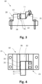
- the Fig. 1 to 10 show several embodiments of a tool 10 with a force sensor 30.
- the force sensor 30 is preferably a piezoelectric force sensor.
- a piezoelectric force sensor has a piezoelectric element, an electrode, an electrical conductor and a contact surface.
- the force sensor 30 measures a tool force acting on the contact surface.
- the contact surface is made of mechanically resistant material and is cylindrical or hollow cylindrical.
- the piezoelectric element is cylindrical or hollow cylindrical and consists of piezoelectric material such as quartz (SiO 2 single crystal), calcium gallo germanate (Ca 3 Ga 2 Ge 4 O 14 or CGG), langasite (La 3 Ga 5 SiO 14 or LGS), tourmaline, gallium orthophosphate, piezoceramic, etc.
- the piezoelectric element is oriented such that it has a high sensitivity for the tool force to be absorbed.
- the piezoelectric element is preferably oriented such that electrical polarization charges are also generated on the same surfaces on which the tool force acts.
- the electrode is also cylindrical or hollow cylindrical and is preferably arranged directly on the surface of the piezoelectric element, which is also affected by the tool force.
- the electrode receives the electrical polarization charges as signals.
- the signals are proportional to the size of the tool force.
- the electrode is preferably electrically insulated from the tool or the tool holder or the contact surface.
- the electrode is preferably an electrically insulating film that is coated on one or both sides with electrically conductive material.
- the An electrical conductor is connected to the electrode and conducts the signals from the electrode to a plug connection for a signal cable, which in turn conducts the signals to an evaluation unit. Alternatively, the electrical conductor connected to the electrode conducts the signals to a radio device, which in turn conducts the signals via a radio link to an evaluation unit.
- the tool 10 comprises a tool holder 20 and a tool shaft 11.
- the tool holder 20 comprises a tool holder 21.
- the tool holder 21 is designed to receive the tool shaft 11.
- the tool holder 21 has a recess 22 and a wedge 23 which can be adjusted by means of a clamping screw 24 so that it can exert a clamping force on the tool shaft 11 when the latter is arranged in the recess 22.
- the tool holder 20 can be fastened to a tool carriage (not shown) by means of fastening screws 25.
- the force sensor 30 is arranged in a recess 12 on the tool shaft 11.
- the recess 12 is arranged in a mechanically resistant material.
- the material is either the tool shaft 11 ( Fig. 1, 2 , 7 ) or a tool holder 20 ( Fig. 5, 6 , 9, 10 ) or an intermediate piece 26 ( Fig. 3, 4 , 8th ).
- the recess 12 is cylindrical or hollow cylindrical.
- the force sensor 30 can have a cylindrical or hollow cylindrical housing made of mechanically resistant material, which housing accommodates the piezoelectric element, the electrode and the electrical conductor. the contact surface, the housing is preferably sealed in a material-to-material manner.
- the force sensor 30 is arranged in the recess 12 with the housing.
- the plug connection is arranged on the housing so that the signal cable in the recess 12 is connected to the electrical conductor via the plug connection.
- the radio device is arranged in the housing so that the electrical conductor in the housing is connected to the radio device.
- the force sensor 30 can also be without a housing, in which case the recess 12 accommodates the piezoelectric element, the electrode and the electrical conductor.
- the plug connection is then arranged in the material around the recess 12 so that the signal cable is connected to the electrical conductor via the plug connection in the material around the recess 12.
- the radio device is arranged in the material around the recess 12 so that the electrical conductor is connected to the radio device.
- the recess 12 is then preferably sealed in a material-to-material manner with the contact surface.
- the force sensor 30 is not completely arranged in the recess 12 in the tool shaft 11. Not completely arranged in the recess 12 in the tool shaft 11 means in the sense of the invention that the force sensor 30 with its contact surface protrudes in some areas over the tool shaft 11. A contact surface of the tool holder 20 and the contact surface of the force sensor 30 lie against each other in a contact plane 31. In the contact plane 31, mechanical contact between the tool shaft 11 and the contact surface of the tool holder 20 occurs solely via the contact surface of the force sensor 30. In this first embodiment of the tool 10, the force sensor 30 measures 100% of the tool force, which acts from the contact surface of the tool holder 11 to the contact surface of the force sensor 30.
- a force component of the measured tool force is 100%. This has the advantage of a force measurement with maximum sensitivity, since no force component acts in a force shunt outside the force sensor 30.
- the tool shaft 11 has a square cross-section. In the top view according to Fig.2 It can be seen that the tool 10 can also have two force sensors 30.
- the force sensor 30 is not completely arranged in the recess 12 in the intermediate piece 26.
- the second embodiment of the tool 10 has a tool holder 21 with a wider recess 22.
- This wider recess 22 not only has space for the tool shaft 11, but also for the intermediate piece 26.
- the force sensor 30 is not completely arranged in the recess 12 in the intermediate piece 26. Not completely arranged in the recess 12 in the intermediate piece 26 means, in the sense of the invention, that the force sensor 30 protrudes in some areas beyond the intermediate piece 26.
- a contact surface of the intermediate piece 26 and the contact surface of the force sensor 30 lie against one another in a contact plane 31. In the contact plane 31, mechanical contact between the intermediate piece 26 and a contact surface of the tool shaft 11 is made solely via the contact surface of the force sensor 30.
- the force sensor 30 measures 100% of the tool force that is transmitted from the contact surface of the tool shaft 11 to the contact surface of the force sensor 30.
- a force component of the measured tool force is 100%.
- the wider recess 22 is partially covered by the intermediate piece 26.
- two force sensors 30, which are arranged in the intermediate piece 26, are in operative connection with the tool shaft 11.
- the force sensor 30 is not completely arranged in the recess 12 in the tool holder 20. Not completely arranged in the recess 12 in the tool holder 20 means, in the sense of the invention, that the force sensor 30 protrudes in some areas beyond the tool holder 20.
- a contact surface of the tool shaft 11 and the contact surface of the force sensor 30 lie against one another in a contact plane 31. In the contact plane 31, mechanical contact between the tool holder 20 and the contact surface of the tool shaft 11 occurs solely via the contact surface of the force sensor 30.
- the force sensor 30 measures 100% of the tool force that acts from the contact surface of the tool shaft 11 onto the contact surface of the force sensor 30.
- a force component of the measured tool force is 100%. This has the advantage of a force measurement with maximum sensitivity, since no force component acts in a force shunt outside the force sensor 30.
- the force sensor 30 is not completely in the Recess 12 in the tool holder 20. Not completely arranged in the recess 12 in the tool holder 20 means, in the sense of the invention, that the force sensor 30 protrudes partially beyond the tool holder 20. A contact surface of an intermediate piece 26 and the contact surface of the force sensor 30 lie against one another in a contact plane 31. In the contact plane 31, mechanical contact between the tool holder 20 and the contact surface of the intermediate piece 26 occurs solely via the contact surface of the force sensor 30.
- the force sensor 30 measures 100% of the tool force that acts from the contact surface of the intermediate piece 26 to the contact surface of the force sensor 30. A force component of the measured tool force is 100%. This has the advantage of a force measurement with maximum sensitivity, since no force component acts in a force shunt outside the force sensor 30.
- the force sensor 30 is arranged completely in the recess 12 in the tool shaft 11.
- arranged completely in the recess 12 in the tool shaft 11 means that the force sensor does not protrude beyond the tool shaft 11.
- the tool shaft 11 and the force sensor 30 arranged completely therein form a common contact surface.
- a first part of the common contact surface is a contact surface of the tool shaft 11, and a second part of the common contact surface is the contact surface of the force sensor 30.
- the common contact surface is, for example, ground flat.
- the common contact surface of the tool shaft 11 and the force sensor 30 and a contact surface of the tool holder 20 lie next to one another in a contact plane 31.
- the force sensor 30 measures less than 100% of the tool force acting on the common contact surface, because a force shunt acts outside the force sensor 30 from the contact surface of the tool shaft 11 to the contact surface of the tool holder 20.
- a force component of the measured tool force is less than 100%.
- the force sensor 30 is arranged completely in the recess 12 in the intermediate piece 26.
- Arranged completely in the recess 12 in the intermediate piece 26 means in the sense of the invention that the force sensor 30 does not protrude beyond the intermediate piece 26.
- the intermediate piece 26 and the force sensor 30 arranged therein form a common contact surface.
- a first part of the common contact surface is a contact surface of the intermediate piece 26, and a second part of the common contact surface is the contact surface of the force sensor 30.
- the contact surface is, for example, ground flat.
- the common contact surface of the intermediate piece 26 and the force sensor 30 and the contact surface of the tool shaft 11 lie against one another in a contact plane 31.
- the force sensor 30 measures less than 100% of the tool force that acts from the contact surface of the tool shaft 11 to the common contact surface, because a force shunt acts outside the force sensor 30 from the contact surface of the tool shaft 11 to the contact surface of the intermediate piece 26.
- a force component of the measured tool force is less than 100%.
- the force sensor 30 is arranged completely in the recess 12 in the tool holder 20. Arranged completely in the recess 12 in the tool holder 20 means in the sense of the invention that the force sensor does not protrude beyond the tool holder 20.
- the tool holder 20 and the force sensor 30 arranged completely therein form a common contact surface.
- a first part of the common contact surface is a contact surface of the tool holder 20, and a second part of the common contact surface is the contact surface of the force sensor 30.
- the common contact surface is, for example, ground flat.
- the common contact surface of the tool holder 20 and the force sensor 30 and a contact surface of the tool shaft 11 lie against one another in a contact plane 31.
- the force sensor 30 measures less than 100% of the tool force acting on the common contact surface, because a force shunt acts outside the force sensor 30 from the contact surface of the tool shaft 11 to the contact surface of the tool holder 20.
- a force component of the measured tool force is less than 100%. This has the advantage of a force measurement with high mechanical stability and high natural frequency, since no mechanical bending of the tool shaft 11 is possible, because the common contact surface of the tool holder 20 and the force sensor 30 is advantageously largely the same size as the contact surface of the tool shaft 11.
- the force sensor 30 is arranged completely in the recess 12 in the tool holder 20. Arranged completely in the recess 12 in the tool holder 20 means in the sense of the invention that the force sensor does not protrude beyond the tool holder 20.
- the tool holder 20 and the force sensor 30 arranged completely therein form a common contact surface.
- a first part of the common contact surface is a contact surface of the tool holder 20, and a second part of the common contact surface is the contact surface of the force sensor 30.
- the common contact surface is, for example, ground flat.
- the common contact surface of the tool holder 20 and the force sensor 30 and a contact surface of an intermediate piece 26 lie against one another in a contact plane 31.
- the force sensor 30 measures less than 100% of the tool force acting on the common contact surface, because a force shunt acts outside the force sensor 30 from the contact surface of the intermediate piece 26 to the contact surface of the tool holder 20.
- a force component of the measured tool force is less than 100%.
Landscapes
- Engineering & Computer Science (AREA)
- Mechanical Engineering (AREA)
- Chemical & Material Sciences (AREA)
- Analytical Chemistry (AREA)
- Physics & Mathematics (AREA)
- General Physics & Mathematics (AREA)
- Force Measurement Appropriate To Specific Purposes (AREA)
- Machine Tool Sensing Apparatuses (AREA)
Claims (10)
- Outil (10) comprenant une tige d'outil (11) reçue dans un logement d'outil (21) d'un porte-outil (20) ; lequel outil (10) comprend en outre exactement un capteur de force (30), lequel capteur de force (30) est disposé dans un évidement (12) au niveau de la tige d'outil (11) ; lequel capteur de force (30) mesure une force de l'outil exercée par la tige d'outil (11) sur le porte-outil (20) pendant le fonctionnement de l'outil (10) ; lequel outil est un outil de coupe, lequel outil de coupe est disposé de manière fixe et sans rotation, dans lequel le porte-outil (20) est sans rotation ;dans lequel l'évidement (12) est fabriqué soit dans la tige d'outil (11) soit dans le porte-outil (20) ;dans lequel le logement d'outil (21) comporte un dispositif de serrage pour serrer la tige d'outil (11) ;caractérisé en ce que le dispositif de serrage comprend une cale (23) ;en ce que le capteur de force (30) est précontraint par une force de précontrainte ; eten ce que ladite force de précontrainte est égale à une force de serrage exercée sur le capteur de force (30) par un dispositif de serrage du logement d'outil (21).
- Outil (10) comprenant une tige d'outil (11) reçue dans un logement d'outil (21) d'un porte-outil (20) ; ledit outil en outre comprenant exactement un capteur de force (30), lequel capteur de force (30) est disposé dans un évidement (12) au niveau de la tige d'outil (11) ; lequel capteur de force (30) mesure une force de l'outil exercée par la tige d'outil (11) sur le porte-outil (20) pendant le fonctionnement de l'outil (10) ; lequel outil (10) est un outil de coupe, ledit outil de coupe étant disposé de manière fixe et sans rotation, dans lequel le porte-outil (20) est sans rotation ;dans lequel le logement d'outil (21) comporte un dispositif de serrage pour serrer la tige d'outil (11) ;caractérisé en ce que le dispositif de serrage comprend une cale (23) ;en ce que le capteur de force (30) est précontraint par une force de précontrainte ; eten ce que ladite force de précontrainte est égale à une force de serrage exercée sur le capteur de force (30) par un dispositif de serrage du logement d'outil (21) ;en ce que l'outil (10) comprend une pièce intermédiaire (26) reçue dans le logement d'outil (21) ; en ce que l'évidement (12) est réalisé dans ladite pièce intermédiaire (26) ; eten ce que le capteur de force (30) mesure une force de l'outil exercée par la tige d'outil (11) sur ladite pièce intermédiaire (26) pendant le fonctionnement de l'outil (10).
- Outil (10) selon l'une quelconque des revendications 1 ou 2, caractérisé en ce que le capteur de force (30) n'est pas entièrement inséré dans l'évidement (12) ou en ce que le capteur de force (30) est entièrement inséré dans l'évidement (12).
- Outil (10) selon l'une quelconque des revendications 1 à 3, caractérisé en ce que le capteur de force (30) est un capteur de force piézoélectrique ; ou en ce que le capteur de force (30) est un capteur de force multi-axes.
- Outil (10) selon l'une quelconque des revendications 1 à 4, caractérisé en ce que le capteur de force (30) est précontraint par une force de précontrainte réglable.
- Outil (10) selon l'une quelconque des revendications 1 à 5, caractérisé en ce qu'il existe une liaison de complémentarité de forme et/ou une liaison de force entre le capteur de force (30) et la tige d'outil (11) et/ou le logement d'outil (21).
- Outil (10) selon la revendication 6, caractérisé en ce que ladite liaison de complémentarité de forme et/ou de force est réversible ou en ce que ladite liaison de complémentarité de forme et/ou de force est reproductible.
- Outil (10) selon l'une quelconque des revendications 1 à 7, caractérisé en ce que le capteur de force (30) est configuré pour transmettre des signaux mesurés par le capteur de force (30) à un dispositif d'évaluation.
- Outil (10) selon l'une quelconque des revendications 1 à 8, caractérisé en ce que le capteur de force (30) est configuré pour permettre la surveillance des signaux mesurés par le capteur de force (30) en temps réel.
- Procédé pour mesurer une force de l'outil en utilisant un outil (10) selon l'une quelconque des revendications 1 à 9, ledit procédé comprenant les étapes consistant à : disposer le capteur de force (30) entre la tige d'outil (11) de l'outil (10) et le logement d'outil (21) du porte-outil (20) ; et serrer le capteur de force (30) au moyen du dispositif de serrage du logement d'outil (21).
Applications Claiming Priority (2)
| Application Number | Priority Date | Filing Date | Title |
|---|---|---|---|
| EP18199541 | 2018-10-10 | ||
| PCT/EP2019/077063 WO2020074434A1 (fr) | 2018-10-10 | 2019-10-07 | Outil et procédé pour mesurer une force d'outil |
Publications (3)
| Publication Number | Publication Date |
|---|---|
| EP3864389A1 EP3864389A1 (fr) | 2021-08-18 |
| EP3864389B1 true EP3864389B1 (fr) | 2024-06-19 |
| EP3864389C0 EP3864389C0 (fr) | 2024-06-19 |
Family
ID=63832295
Family Applications (1)
| Application Number | Title | Priority Date | Filing Date |
|---|---|---|---|
| EP19779520.6A Active EP3864389B1 (fr) | 2018-10-10 | 2019-10-07 | Outil et procede de mesure d'une force sur l'outil |
Country Status (5)
| Country | Link |
|---|---|
| US (1) | US12128516B2 (fr) |
| EP (1) | EP3864389B1 (fr) |
| JP (1) | JP7097510B2 (fr) |
| CN (1) | CN112888926A (fr) |
| WO (1) | WO2020074434A1 (fr) |
Families Citing this family (5)
| Publication number | Priority date | Publication date | Assignee | Title |
|---|---|---|---|---|
| DE102020106038B3 (de) * | 2020-03-05 | 2021-03-11 | Hartmetall-Werkzeugfabrik Paul Horn Gmbh | Spanabhebendes Werkzeug und Werkzeugmaschine mit einem solchen Werkzeug |
| EP3881969A1 (fr) * | 2020-03-19 | 2021-09-22 | Kistler Holding AG | Machine d'usinage par enlèvement de matière dotée d'un capteur de force, utilisation d'une telle machine d'usinage par enlèvement de matière ainsi que procédé d'étalonnage du capteur de force d'une telle machine d'usinage par enlèvement de matière |
| EP3967449A1 (fr) | 2020-09-09 | 2022-03-16 | Hartmetall-Werkzeugfabrik Paul Horn GmbH | Porte-outils et système d'outils doté d'un tel porte-outils |
| TWI799044B (zh) * | 2021-12-29 | 2023-04-11 | 財團法人工業技術研究院 | 具力感測器的刀把 |
| KR102597638B1 (ko) * | 2022-12-26 | 2023-11-02 | 한전케이피에스 주식회사 | 클램핑 포스 측정장치 |
Citations (3)
| Publication number | Priority date | Publication date | Assignee | Title |
|---|---|---|---|---|
| US20160045994A1 (en) * | 2013-03-25 | 2016-02-18 | Centre Technique De L'industrie Du Decolletage | Insert Holder For A Machine Tool |
| CN106363461A (zh) * | 2016-11-11 | 2017-02-01 | 沈阳建筑大学 | 一种车削力测量装置及方法 |
| CN207888246U (zh) * | 2018-01-24 | 2018-09-21 | 安徽省恒泰动力科技有限公司 | 一种可在线采集刀具切削力信号的夹具 |
Family Cites Families (40)
| Publication number | Priority date | Publication date | Assignee | Title |
|---|---|---|---|---|
| US2054787A (en) * | 1930-12-10 | 1936-09-22 | Western Electric Co | Measuring device |
| US3497935A (en) * | 1967-02-15 | 1970-03-03 | C & L Machine Shop Inc | Cut-off tool assembly |
| JPS4712583U (fr) | 1971-03-11 | 1972-10-14 | ||
| FR2155400A5 (fr) * | 1971-09-30 | 1973-05-18 | Licentia Gmbh | |
| JPS5638894B2 (fr) * | 1972-12-11 | 1981-09-09 | ||
| US3872285A (en) * | 1974-05-31 | 1975-03-18 | Westinghouse Electric Corp | Control system for sensing the vibration and lateral force on a cutting tool |
| US4080854A (en) * | 1976-08-27 | 1978-03-28 | Hardinge Brothers, Inc. | Adjustable tool holder |
| US4555955A (en) * | 1984-01-27 | 1985-12-03 | Eaton Corporation | Combination loading transducer |
| US4671147A (en) * | 1985-05-30 | 1987-06-09 | General Electric Company | Instrumented tool holder |
| EP0321599B1 (fr) * | 1987-12-22 | 1992-10-28 | Kistler Instrumente AG | Dispositif pour mesurer les forces d'usinage dans les machines-outils |
| DE3908175C2 (de) * | 1988-03-14 | 1994-04-14 | Elco Co | Belastungs-Detektorvorrichtung |
| DE3831331C2 (de) * | 1988-09-15 | 1997-07-03 | Betr Forsch Inst Angew Forsch | Umlenkmeßrolle aus gegeneinander unverdrehbaren Ringen mit Kraftmeßgebern für die Ermittlung der Spannungsverteilung von ungelenkten, biegsamen Bändern |
| CH680421A5 (fr) | 1989-12-22 | 1992-08-31 | Kistler Instrumente Ag | |
| CH682182A5 (fr) | 1990-05-31 | 1993-07-30 | Kk Holding Ag | |
| US5251522A (en) * | 1992-11-02 | 1993-10-12 | Chin Long Wu | Protective apparatus preventing lathe tool from breaking |
| JP3688707B2 (ja) * | 1993-09-14 | 2005-08-31 | ヴェルナー クルフト | 力測定装置 |
| GB9417556D0 (en) * | 1994-09-01 | 1994-10-19 | Rigibore Ltd | Cutting tool holder |
| JP4113986B2 (ja) * | 1998-08-12 | 2008-07-09 | エヌティーエンジニアリング株式会社 | 作業機械の作動状態検出装置 |
| SE514525E (sv) * | 1998-10-22 | 2010-02-16 | Staffansboda Cie Ab | Anordning och metod för styrning av vibrationer samt verktygshållare |
| SE519487C2 (sv) * | 1998-10-22 | 2003-03-04 | Rolf Zimmergren | Metod och anordning för vibrationsstyrning vid borrande svarvning samt verktygshållare för borrande svarvning |
| SE517790C2 (sv) * | 1999-02-10 | 2002-07-16 | Sandvik Ab | Verktyg för spånavskiljande bearbetning |
| EP1583941B1 (fr) * | 2003-01-17 | 2011-12-28 | Kistler Holding AG | Element de precontrainte pour des capteurs |
| US7234379B2 (en) * | 2005-06-28 | 2007-06-26 | Ingvar Claesson | Device and a method for preventing or reducing vibrations in a cutting tool |
| JP2007054924A (ja) * | 2005-08-26 | 2007-03-08 | Toyota Motor Corp | 工具把持力測定システムおよび工具把持力測定方法 |
| DE102007005222A1 (de) * | 2006-02-03 | 2007-08-09 | Ceramtec Ag Innovative Ceramic Engineering | Einsatz von piezokeramischen Wandlern zur Regelung der spanabhebenden Werkstückbearbeitung |
| DE102007001620B4 (de) * | 2007-01-04 | 2009-08-20 | Fraunhofer-Gesellschaft zur Förderung der angewandten Forschung e.V. | Verfahren zum Betrieb einer Bearbeitungsmaschine sowie Werkzeughalterung |
| JP2011518048A (ja) * | 2008-03-17 | 2011-06-23 | エイ. サプロック,クリストファー | スマートマシニングシステム及びそれに用いられるスマートツールホルダー |
| TWI457196B (zh) * | 2008-12-05 | 2014-10-21 | Ind Tech Res Inst | 可即時監測工作狀態之工具機主軸結構 |
| JP5638894B2 (ja) | 2010-09-17 | 2014-12-10 | 株式会社Nttファシリティーズ | 電力変換装置及び直流給電システム |
| CN102179705B (zh) * | 2011-04-21 | 2013-04-17 | 株洲钻石切削刀具股份有限公司 | 用于高速切削的切削刀具 |
| CN102873353B (zh) * | 2012-10-15 | 2015-02-18 | 哈尔滨工业大学 | 具有微小三向切削力测量系统的智能刀具 |
| US8726740B1 (en) * | 2012-12-13 | 2014-05-20 | King Fahd University Of Petroleum And Minerals | Multi-axis dynamometer |
| CN103111643A (zh) * | 2013-03-12 | 2013-05-22 | 哈尔滨工业大学 | 一种无线感知切削状态的智能金刚石刀具 |
| DE102013005555A1 (de) | 2013-03-28 | 2014-10-30 | Klaus Reins | Motorkolben - Hochleistungskolben |
| CH708837A1 (de) | 2013-11-14 | 2015-05-15 | Kistler Holding Ag | Piezoelektrischer Kraftsensor mit lösbarer elektrischer Verbindung zwischen Elektrode und Kontaktpin. |
| CH709459A1 (de) * | 2014-04-02 | 2015-10-15 | Kistler Holding Ag | Vorspannvorrichtung einer Kraftmessvorrichtung, Kraftmessvorrichtung und Verfahren zu deren Einführung in Aussparungen von Maschinenteilen. |
| DE102015100655A1 (de) | 2015-01-19 | 2016-07-21 | Cord Winkelmann | Linearführungseinrichtung für eine Vorschubachse einer Werkzeugmaschine |
| DE102015016221A1 (de) * | 2015-12-04 | 2017-06-08 | Michael Weinig Ag | Andruckvorrichtung für eine Werkzeugmaschine zur Bearbeitung von Werkstücken aus Holz, Kunststoff und dergleichen sowie eine Werkzeugmaschine mit wenigstens einer Andruckvorrichtung |
| CN106584210B (zh) * | 2017-02-06 | 2018-08-24 | 广东工业大学 | 一种用于精密切削的智能刀具系统 |
| CN107322368B (zh) * | 2017-06-15 | 2019-04-16 | 西安交通大学 | 一种基于锰铜合金微纳敏感单元的切削力测量装置 |
-
2019
- 2019-10-07 CN CN201980067173.6A patent/CN112888926A/zh active Pending
- 2019-10-07 US US17/278,752 patent/US12128516B2/en active Active
- 2019-10-07 EP EP19779520.6A patent/EP3864389B1/fr active Active
- 2019-10-07 WO PCT/EP2019/077063 patent/WO2020074434A1/fr not_active Ceased
- 2019-10-07 JP JP2021519814A patent/JP7097510B2/ja active Active
Patent Citations (3)
| Publication number | Priority date | Publication date | Assignee | Title |
|---|---|---|---|---|
| US20160045994A1 (en) * | 2013-03-25 | 2016-02-18 | Centre Technique De L'industrie Du Decolletage | Insert Holder For A Machine Tool |
| CN106363461A (zh) * | 2016-11-11 | 2017-02-01 | 沈阳建筑大学 | 一种车削力测量装置及方法 |
| CN207888246U (zh) * | 2018-01-24 | 2018-09-21 | 安徽省恒泰动力科技有限公司 | 一种可在线采集刀具切削力信号的夹具 |
Also Published As
| Publication number | Publication date |
|---|---|
| JP7097510B2 (ja) | 2022-07-07 |
| CN112888926A (zh) | 2021-06-01 |
| JP2022502666A (ja) | 2022-01-11 |
| US20220032416A1 (en) | 2022-02-03 |
| US12128516B2 (en) | 2024-10-29 |
| EP3864389C0 (fr) | 2024-06-19 |
| WO2020074434A1 (fr) | 2020-04-16 |
| EP3864389A1 (fr) | 2021-08-18 |
Similar Documents
| Publication | Publication Date | Title |
|---|---|---|
| EP3864389A1 (fr) | Outil et procédé pour mesurer une force d'outil | |
| DE2016118C3 (de) | Verfahren zur Messung von Eigenspannungen in Bauteilen des Maschinen- oder Apparatebaues und Vorrichtung zur Durchführung dieses Verfahrens | |
| EP2103379B1 (fr) | Système de mesure de force intégré au mandrin | |
| DE6940548U (de) | Mehrkomponenten- kraft- und momentenmessanordnung | |
| EP3161445B1 (fr) | Dispositif de test pour tester des systèmes à vis et procédé de test pour celui-ci | |
| EP3344965B1 (fr) | Dispositif de detection de force et de couple | |
| EP0321599B1 (fr) | Dispositif pour mesurer les forces d'usinage dans les machines-outils | |
| DE102007001620B4 (de) | Verfahren zum Betrieb einer Bearbeitungsmaschine sowie Werkzeughalterung | |
| DE102018219093A1 (de) | Verfahren zur Prüfung eines Reibwerts einer Schraube sowie Reibwertprüfstand für Schrauben | |
| EP2829859A2 (fr) | Procédé et système de mesure destinés à déterminer des déformations d'un corps géométrique au moyen de capteurs de mesure de déformation ou de dynamomètre | |
| DE102020114431A1 (de) | Werkzeughalter und Verfahren zur Drehbearbeitung eines Werkstücks | |
| EP3967450A1 (fr) | Porte-outil et système d'outil doté d'un tel porte-outil | |
| EP0682235B1 (fr) | Appareil et procédé pour calibrer une jauge d'un dispositif de mesure | |
| EP2312261A1 (fr) | Dispositif de vérification de l'exactitude de machines-outils et dispositifs de mesure | |
| DE102017116448B4 (de) | Kraftmesseinrichtung mit Störgrößenkompensation | |
| DE102004033925B4 (de) | Drehmoment-Messaufnehmer | |
| EP1466157B1 (fr) | Dispositif de mesure de force a faible taux de vibrations dans des essais de traction dynamiques rapides sur des echantillons de materiaux | |
| EP4058236B1 (fr) | Machine d'enlèvement de copeaux pourvu d'un capteur de force, procédé de fonctionnement d'une telle machine d'enlèvement de copeaux ainsi que procédé d'étalonnage du capteur de force d'une telle machine d'enlèvement de copeaux | |
| CH705388B1 (de) | Werkzeug. | |
| DE102023204633A1 (de) | Sensorsystem und Bearbeitungsmaschine | |
| DE102006036746B4 (de) | Positionsmesseinrichtung | |
| DE68915549T2 (de) | Verfahren und vorrichtung zum messen der schneidkräfte einer werkzeugmaschine. | |
| DE4432582C2 (de) | Vorrichtung zur Radialkraftmessung an Zentrierspitzen von Werkzeugmaschinen | |
| EP3881969A1 (fr) | Machine d'usinage par enlèvement de matière dotée d'un capteur de force, utilisation d'une telle machine d'usinage par enlèvement de matière ainsi que procédé d'étalonnage du capteur de force d'une telle machine d'usinage par enlèvement de matière | |
| DE10233539A1 (de) | Verfahren und Vorrichtung zur Messung von Werkstückbohrungen |
Legal Events
| Date | Code | Title | Description |
|---|---|---|---|
| STAA | Information on the status of an ep patent application or granted ep patent |
Free format text: STATUS: UNKNOWN |
|
| STAA | Information on the status of an ep patent application or granted ep patent |
Free format text: STATUS: THE INTERNATIONAL PUBLICATION HAS BEEN MADE |
|
| PUAI | Public reference made under article 153(3) epc to a published international application that has entered the european phase |
Free format text: ORIGINAL CODE: 0009012 |
|
| STAA | Information on the status of an ep patent application or granted ep patent |
Free format text: STATUS: REQUEST FOR EXAMINATION WAS MADE |
|
| 17P | Request for examination filed |
Effective date: 20210407 |
|
| AK | Designated contracting states |
Kind code of ref document: A1 Designated state(s): AL AT BE BG CH CY CZ DE DK EE ES FI FR GB GR HR HU IE IS IT LI LT LU LV MC MK MT NL NO PL PT RO RS SE SI SK SM TR |
|
| DAV | Request for validation of the european patent (deleted) | ||
| DAX | Request for extension of the european patent (deleted) | ||
| STAA | Information on the status of an ep patent application or granted ep patent |
Free format text: STATUS: EXAMINATION IS IN PROGRESS |
|
| 17Q | First examination report despatched |
Effective date: 20220506 |
|
| GRAP | Despatch of communication of intention to grant a patent |
Free format text: ORIGINAL CODE: EPIDOSNIGR1 |
|
| STAA | Information on the status of an ep patent application or granted ep patent |
Free format text: STATUS: GRANT OF PATENT IS INTENDED |
|
| INTG | Intention to grant announced |
Effective date: 20240314 |
|
| GRAS | Grant fee paid |
Free format text: ORIGINAL CODE: EPIDOSNIGR3 |
|
| GRAA | (expected) grant |
Free format text: ORIGINAL CODE: 0009210 |
|
| STAA | Information on the status of an ep patent application or granted ep patent |
Free format text: STATUS: THE PATENT HAS BEEN GRANTED |
|
| AK | Designated contracting states |
Kind code of ref document: B1 Designated state(s): AL AT BE BG CH CY CZ DE DK EE ES FI FR GB GR HR HU IE IS IT LI LT LU LV MC MK MT NL NO PL PT RO RS SE SI SK SM TR |
|
| REG | Reference to a national code |
Ref country code: GB Ref legal event code: FG4D Free format text: NOT ENGLISH |
|
| REG | Reference to a national code |
Ref country code: CH Ref legal event code: EP |
|
| REG | Reference to a national code |
Ref country code: DE Ref legal event code: R096 Ref document number: 502019011490 Country of ref document: DE |
|
| U01 | Request for unitary effect filed |
Effective date: 20240619 |
|
| U07 | Unitary effect registered |
Designated state(s): AT BE BG DE DK EE FI FR IT LT LU LV MT NL PT SE SI Effective date: 20240627 |
|
| PG25 | Lapsed in a contracting state [announced via postgrant information from national office to epo] |
Ref country code: HR Free format text: LAPSE BECAUSE OF FAILURE TO SUBMIT A TRANSLATION OF THE DESCRIPTION OR TO PAY THE FEE WITHIN THE PRESCRIBED TIME-LIMIT Effective date: 20240619 |
|
| PG25 | Lapsed in a contracting state [announced via postgrant information from national office to epo] |
Ref country code: GR Free format text: LAPSE BECAUSE OF FAILURE TO SUBMIT A TRANSLATION OF THE DESCRIPTION OR TO PAY THE FEE WITHIN THE PRESCRIBED TIME-LIMIT Effective date: 20240920 |
|
| PG25 | Lapsed in a contracting state [announced via postgrant information from national office to epo] |
Ref country code: NO Free format text: LAPSE BECAUSE OF FAILURE TO SUBMIT A TRANSLATION OF THE DESCRIPTION OR TO PAY THE FEE WITHIN THE PRESCRIBED TIME-LIMIT Effective date: 20240919 Ref country code: HR Free format text: LAPSE BECAUSE OF FAILURE TO SUBMIT A TRANSLATION OF THE DESCRIPTION OR TO PAY THE FEE WITHIN THE PRESCRIBED TIME-LIMIT Effective date: 20240619 Ref country code: GR Free format text: LAPSE BECAUSE OF FAILURE TO SUBMIT A TRANSLATION OF THE DESCRIPTION OR TO PAY THE FEE WITHIN THE PRESCRIBED TIME-LIMIT Effective date: 20240920 Ref country code: RS Free format text: LAPSE BECAUSE OF FAILURE TO SUBMIT A TRANSLATION OF THE DESCRIPTION OR TO PAY THE FEE WITHIN THE PRESCRIBED TIME-LIMIT Effective date: 20240919 |
|
| U20 | Renewal fee for the european patent with unitary effect paid |
Year of fee payment: 6 Effective date: 20241025 |
|
| PG25 | Lapsed in a contracting state [announced via postgrant information from national office to epo] |
Ref country code: PL Free format text: LAPSE BECAUSE OF FAILURE TO SUBMIT A TRANSLATION OF THE DESCRIPTION OR TO PAY THE FEE WITHIN THE PRESCRIBED TIME-LIMIT Effective date: 20240619 |
|
| PG25 | Lapsed in a contracting state [announced via postgrant information from national office to epo] |
Ref country code: IS Free format text: LAPSE BECAUSE OF FAILURE TO SUBMIT A TRANSLATION OF THE DESCRIPTION OR TO PAY THE FEE WITHIN THE PRESCRIBED TIME-LIMIT Effective date: 20241019 |
|
| PG25 | Lapsed in a contracting state [announced via postgrant information from national office to epo] |
Ref country code: RO Free format text: LAPSE BECAUSE OF FAILURE TO SUBMIT A TRANSLATION OF THE DESCRIPTION OR TO PAY THE FEE WITHIN THE PRESCRIBED TIME-LIMIT Effective date: 20240619 Ref country code: SK Free format text: LAPSE BECAUSE OF FAILURE TO SUBMIT A TRANSLATION OF THE DESCRIPTION OR TO PAY THE FEE WITHIN THE PRESCRIBED TIME-LIMIT Effective date: 20240619 |
|
| PG25 | Lapsed in a contracting state [announced via postgrant information from national office to epo] |
Ref country code: ES Free format text: LAPSE BECAUSE OF FAILURE TO SUBMIT A TRANSLATION OF THE DESCRIPTION OR TO PAY THE FEE WITHIN THE PRESCRIBED TIME-LIMIT Effective date: 20240619 Ref country code: SM Free format text: LAPSE BECAUSE OF FAILURE TO SUBMIT A TRANSLATION OF THE DESCRIPTION OR TO PAY THE FEE WITHIN THE PRESCRIBED TIME-LIMIT Effective date: 20240619 |
|
| PG25 | Lapsed in a contracting state [announced via postgrant information from national office to epo] |
Ref country code: SM Free format text: LAPSE BECAUSE OF FAILURE TO SUBMIT A TRANSLATION OF THE DESCRIPTION OR TO PAY THE FEE WITHIN THE PRESCRIBED TIME-LIMIT Effective date: 20240619 Ref country code: SK Free format text: LAPSE BECAUSE OF FAILURE TO SUBMIT A TRANSLATION OF THE DESCRIPTION OR TO PAY THE FEE WITHIN THE PRESCRIBED TIME-LIMIT Effective date: 20240619 Ref country code: RO Free format text: LAPSE BECAUSE OF FAILURE TO SUBMIT A TRANSLATION OF THE DESCRIPTION OR TO PAY THE FEE WITHIN THE PRESCRIBED TIME-LIMIT Effective date: 20240619 Ref country code: PL Free format text: LAPSE BECAUSE OF FAILURE TO SUBMIT A TRANSLATION OF THE DESCRIPTION OR TO PAY THE FEE WITHIN THE PRESCRIBED TIME-LIMIT Effective date: 20240619 Ref country code: IS Free format text: LAPSE BECAUSE OF FAILURE TO SUBMIT A TRANSLATION OF THE DESCRIPTION OR TO PAY THE FEE WITHIN THE PRESCRIBED TIME-LIMIT Effective date: 20241019 Ref country code: ES Free format text: LAPSE BECAUSE OF FAILURE TO SUBMIT A TRANSLATION OF THE DESCRIPTION OR TO PAY THE FEE WITHIN THE PRESCRIBED TIME-LIMIT Effective date: 20240619 |
|
| PLBE | No opposition filed within time limit |
Free format text: ORIGINAL CODE: 0009261 |
|
| STAA | Information on the status of an ep patent application or granted ep patent |
Free format text: STATUS: NO OPPOSITION FILED WITHIN TIME LIMIT |
|
| 26N | No opposition filed |
Effective date: 20250320 |
|
| PG25 | Lapsed in a contracting state [announced via postgrant information from national office to epo] |
Ref country code: MC Free format text: LAPSE BECAUSE OF FAILURE TO SUBMIT A TRANSLATION OF THE DESCRIPTION OR TO PAY THE FEE WITHIN THE PRESCRIBED TIME-LIMIT Effective date: 20240619 |
|
| PG25 | Lapsed in a contracting state [announced via postgrant information from national office to epo] |
Ref country code: IE Free format text: LAPSE BECAUSE OF NON-PAYMENT OF DUE FEES Effective date: 20241007 |
|
| U20 | Renewal fee for the european patent with unitary effect paid |
Year of fee payment: 7 Effective date: 20251028 |
|
| REG | Reference to a national code |
Ref country code: CH Ref legal event code: U11 Free format text: ST27 STATUS EVENT CODE: U-0-0-U10-U11 (AS PROVIDED BY THE NATIONAL OFFICE) Effective date: 20251208 |
|
| PGFP | Annual fee paid to national office [announced via postgrant information from national office to epo] |
Ref country code: GB Payment date: 20251022 Year of fee payment: 7 |
|
| PGFP | Annual fee paid to national office [announced via postgrant information from national office to epo] |
Ref country code: CH Payment date: 20251208 Year of fee payment: 7 |
|
| PGFP | Annual fee paid to national office [announced via postgrant information from national office to epo] |
Ref country code: CZ Payment date: 20250930 Year of fee payment: 7 |
|
| PG25 | Lapsed in a contracting state [announced via postgrant information from national office to epo] |
Ref country code: CY Free format text: LAPSE BECAUSE OF FAILURE TO SUBMIT A TRANSLATION OF THE DESCRIPTION OR TO PAY THE FEE WITHIN THE PRESCRIBED TIME-LIMIT; INVALID AB INITIO Effective date: 20191007 |
|
| PG25 | Lapsed in a contracting state [announced via postgrant information from national office to epo] |
Ref country code: HU Free format text: LAPSE BECAUSE OF FAILURE TO SUBMIT A TRANSLATION OF THE DESCRIPTION OR TO PAY THE FEE WITHIN THE PRESCRIBED TIME-LIMIT; INVALID AB INITIO Effective date: 20191007 |