EP3864468B1 - Procédé de détermination du statut de connexion d'un dispositif de recharge de toner - Google Patents
Procédé de détermination du statut de connexion d'un dispositif de recharge de toner Download PDFInfo
- Publication number
- EP3864468B1 EP3864468B1 EP19910525.5A EP19910525A EP3864468B1 EP 3864468 B1 EP3864468 B1 EP 3864468B1 EP 19910525 A EP19910525 A EP 19910525A EP 3864468 B1 EP3864468 B1 EP 3864468B1
- Authority
- EP
- European Patent Office
- Prior art keywords
- toner
- state
- refill apparatus
- toner refill
- resistance
- Prior art date
- Legal status (The legal status is an assumption and is not a legal conclusion. Google has not performed a legal analysis and makes no representation as to the accuracy of the status listed.)
- Active
Links
Images






Classifications
-
- G—PHYSICS
- G03—PHOTOGRAPHY; CINEMATOGRAPHY; ANALOGOUS TECHNIQUES USING WAVES OTHER THAN OPTICAL WAVES; ELECTROGRAPHY; HOLOGRAPHY
- G03G—ELECTROGRAPHY; ELECTROPHOTOGRAPHY; MAGNETOGRAPHY
- G03G15/00—Apparatus for electrographic processes using a charge pattern
- G03G15/06—Apparatus for electrographic processes using a charge pattern for developing
- G03G15/08—Apparatus for electrographic processes using a charge pattern for developing using a solid developer, e.g. powder developer
- G03G15/0822—Arrangements for preparing, mixing, supplying or dispensing developer
- G03G15/0863—Arrangements for preparing, mixing, supplying or dispensing developer provided with identifying means or means for storing process- or use parameters, e.g. an electronic memory
-
- G—PHYSICS
- G03—PHOTOGRAPHY; CINEMATOGRAPHY; ANALOGOUS TECHNIQUES USING WAVES OTHER THAN OPTICAL WAVES; ELECTROGRAPHY; HOLOGRAPHY
- G03G—ELECTROGRAPHY; ELECTROPHOTOGRAPHY; MAGNETOGRAPHY
- G03G15/00—Apparatus for electrographic processes using a charge pattern
- G03G15/55—Self-diagnostics; Malfunction or lifetime display
- G03G15/553—Monitoring or warning means for exhaustion or lifetime end of consumables, e.g. indication of insufficient copy sheet quantity for a job
- G03G15/556—Monitoring or warning means for exhaustion or lifetime end of consumables, e.g. indication of insufficient copy sheet quantity for a job for toner consumption, e.g. pixel counting, toner coverage detection or toner density measurement
-
- G—PHYSICS
- G03—PHOTOGRAPHY; CINEMATOGRAPHY; ANALOGOUS TECHNIQUES USING WAVES OTHER THAN OPTICAL WAVES; ELECTROGRAPHY; HOLOGRAPHY
- G03G—ELECTROGRAPHY; ELECTROPHOTOGRAPHY; MAGNETOGRAPHY
- G03G15/00—Apparatus for electrographic processes using a charge pattern
- G03G15/06—Apparatus for electrographic processes using a charge pattern for developing
- G03G15/08—Apparatus for electrographic processes using a charge pattern for developing using a solid developer, e.g. powder developer
- G03G15/0822—Arrangements for preparing, mixing, supplying or dispensing developer
- G03G15/0865—Arrangements for supplying new developer
-
- G—PHYSICS
- G03—PHOTOGRAPHY; CINEMATOGRAPHY; ANALOGOUS TECHNIQUES USING WAVES OTHER THAN OPTICAL WAVES; ELECTROGRAPHY; HOLOGRAPHY
- G03G—ELECTROGRAPHY; ELECTROPHOTOGRAPHY; MAGNETOGRAPHY
- G03G15/00—Apparatus for electrographic processes using a charge pattern
- G03G15/06—Apparatus for electrographic processes using a charge pattern for developing
- G03G15/08—Apparatus for electrographic processes using a charge pattern for developing using a solid developer, e.g. powder developer
- G03G15/0822—Arrangements for preparing, mixing, supplying or dispensing developer
- G03G15/0865—Arrangements for supplying new developer
- G03G15/0867—Arrangements for supplying new developer cylindrical developer cartridges, e.g. toner bottles for the developer replenishing opening
-
- G—PHYSICS
- G03—PHOTOGRAPHY; CINEMATOGRAPHY; ANALOGOUS TECHNIQUES USING WAVES OTHER THAN OPTICAL WAVES; ELECTROGRAPHY; HOLOGRAPHY
- G03G—ELECTROGRAPHY; ELECTROPHOTOGRAPHY; MAGNETOGRAPHY
- G03G15/00—Apparatus for electrographic processes using a charge pattern
- G03G15/06—Apparatus for electrographic processes using a charge pattern for developing
- G03G15/08—Apparatus for electrographic processes using a charge pattern for developing using a solid developer, e.g. powder developer
- G03G15/0822—Arrangements for preparing, mixing, supplying or dispensing developer
- G03G15/0877—Arrangements for metering and dispensing developer from a developer cartridge into the development unit
-
- G—PHYSICS
- G03—PHOTOGRAPHY; CINEMATOGRAPHY; ANALOGOUS TECHNIQUES USING WAVES OTHER THAN OPTICAL WAVES; ELECTROGRAPHY; HOLOGRAPHY
- G03G—ELECTROGRAPHY; ELECTROPHOTOGRAPHY; MAGNETOGRAPHY
- G03G21/00—Arrangements not provided for by groups G03G13/00 - G03G19/00, e.g. cleaning, elimination of residual charge
- G03G21/14—Electronic sequencing control
-
- G—PHYSICS
- G03—PHOTOGRAPHY; CINEMATOGRAPHY; ANALOGOUS TECHNIQUES USING WAVES OTHER THAN OPTICAL WAVES; ELECTROGRAPHY; HOLOGRAPHY
- G03G—ELECTROGRAPHY; ELECTROPHOTOGRAPHY; MAGNETOGRAPHY
- G03G21/00—Arrangements not provided for by groups G03G13/00 - G03G19/00, e.g. cleaning, elimination of residual charge
- G03G21/16—Mechanical means for facilitating the maintenance of the apparatus, e.g. modular arrangements
- G03G21/1661—Mechanical means for facilitating the maintenance of the apparatus, e.g. modular arrangements means for handling parts of the apparatus in the apparatus
- G03G21/1676—Mechanical means for facilitating the maintenance of the apparatus, e.g. modular arrangements means for handling parts of the apparatus in the apparatus for the developer unit
-
- G—PHYSICS
- G03—PHOTOGRAPHY; CINEMATOGRAPHY; ANALOGOUS TECHNIQUES USING WAVES OTHER THAN OPTICAL WAVES; ELECTROGRAPHY; HOLOGRAPHY
- G03G—ELECTROGRAPHY; ELECTROPHOTOGRAPHY; MAGNETOGRAPHY
- G03G21/00—Arrangements not provided for by groups G03G13/00 - G03G19/00, e.g. cleaning, elimination of residual charge
- G03G21/16—Mechanical means for facilitating the maintenance of the apparatus, e.g. modular arrangements
- G03G21/18—Mechanical means for facilitating the maintenance of the apparatus, e.g. modular arrangements using a processing cartridge, whereby the process cartridge comprises at least two image processing means in a single unit
- G03G21/1875—Mechanical means for facilitating the maintenance of the apparatus, e.g. modular arrangements using a processing cartridge, whereby the process cartridge comprises at least two image processing means in a single unit provided with identifying means or means for storing process- or use parameters, e.g. lifetime of the cartridge
- G03G21/1878—Electronically readable memory
-
- G—PHYSICS
- G03—PHOTOGRAPHY; CINEMATOGRAPHY; ANALOGOUS TECHNIQUES USING WAVES OTHER THAN OPTICAL WAVES; ELECTROGRAPHY; HOLOGRAPHY
- G03G—ELECTROGRAPHY; ELECTROPHOTOGRAPHY; MAGNETOGRAPHY
- G03G15/00—Apparatus for electrographic processes using a charge pattern
- G03G15/06—Apparatus for electrographic processes using a charge pattern for developing
- G03G15/08—Apparatus for electrographic processes using a charge pattern for developing using a solid developer, e.g. powder developer
- G03G15/0822—Arrangements for preparing, mixing, supplying or dispensing developer
- G03G15/0848—Arrangements for testing or measuring developer properties or quality, e.g. charge, size, flowability
- G03G15/0856—Detection or control means for the developer level
- G03G15/086—Detection or control means for the developer level the level being measured by electro-magnetic means
-
- G—PHYSICS
- G03—PHOTOGRAPHY; CINEMATOGRAPHY; ANALOGOUS TECHNIQUES USING WAVES OTHER THAN OPTICAL WAVES; ELECTROGRAPHY; HOLOGRAPHY
- G03G—ELECTROGRAPHY; ELECTROPHOTOGRAPHY; MAGNETOGRAPHY
- G03G15/00—Apparatus for electrographic processes using a charge pattern
- G03G15/06—Apparatus for electrographic processes using a charge pattern for developing
- G03G15/08—Apparatus for electrographic processes using a charge pattern for developing using a solid developer, e.g. powder developer
- G03G15/0894—Reconditioning of the developer unit, i.e. reusing or recycling parts of the unit, e.g. resealing of the unit before refilling with toner
-
- G—PHYSICS
- G03—PHOTOGRAPHY; CINEMATOGRAPHY; ANALOGOUS TECHNIQUES USING WAVES OTHER THAN OPTICAL WAVES; ELECTROGRAPHY; HOLOGRAPHY
- G03G—ELECTROGRAPHY; ELECTROPHOTOGRAPHY; MAGNETOGRAPHY
- G03G21/00—Arrangements not provided for by groups G03G13/00 - G03G19/00, e.g. cleaning, elimination of residual charge
- G03G21/16—Mechanical means for facilitating the maintenance of the apparatus, e.g. modular arrangements
- G03G21/18—Mechanical means for facilitating the maintenance of the apparatus, e.g. modular arrangements using a processing cartridge, whereby the process cartridge comprises at least two image processing means in a single unit
- G03G21/1875—Mechanical means for facilitating the maintenance of the apparatus, e.g. modular arrangements using a processing cartridge, whereby the process cartridge comprises at least two image processing means in a single unit provided with identifying means or means for storing process- or use parameters, e.g. lifetime of the cartridge
- G03G21/1878—Electronically readable memory
- G03G21/1892—Electronically readable memory for presence detection, authentication
-
- G—PHYSICS
- G03—PHOTOGRAPHY; CINEMATOGRAPHY; ANALOGOUS TECHNIQUES USING WAVES OTHER THAN OPTICAL WAVES; ELECTROGRAPHY; HOLOGRAPHY
- G03G—ELECTROGRAPHY; ELECTROPHOTOGRAPHY; MAGNETOGRAPHY
- G03G2215/00—Apparatus for electrophotographic processes
- G03G2215/06—Developing structures, details
- G03G2215/066—Toner cartridge or other attachable and detachable container for supplying developer material to replace the used material
- G03G2215/0685—Toner cartridge or other attachable and detachable container for supplying developer material to replace the used material fulfilling a continuous function within the electrographic apparatus during the use of the supplied developer material, e.g. toner discharge on demand, storing residual toner, not acting as a passive closure for the developer replenishing opening
-
- G—PHYSICS
- G03—PHOTOGRAPHY; CINEMATOGRAPHY; ANALOGOUS TECHNIQUES USING WAVES OTHER THAN OPTICAL WAVES; ELECTROGRAPHY; HOLOGRAPHY
- G03G—ELECTROGRAPHY; ELECTROPHOTOGRAPHY; MAGNETOGRAPHY
- G03G2215/00—Apparatus for electrophotographic processes
- G03G2215/06—Developing structures, details
- G03G2215/066—Toner cartridge or other attachable and detachable container for supplying developer material to replace the used material
- G03G2215/0695—Toner cartridge or other attachable and detachable container for supplying developer material to replace the used material using identification means or means for storing process or use parameters
- G03G2215/0697—Toner cartridge or other attachable and detachable container for supplying developer material to replace the used material using identification means or means for storing process or use parameters being an electronically readable memory
Definitions
- An image forming apparatus refers to an apparatus that prints printing data generated at a terminal apparatus like a computer on printing paper.
- An image forming apparatus may include a copier, a printer, a scanner, a facsimile, a multi-function printer (MFP) that integrally implements the functions of the aforementioned apparatuses through one apparatus, etc.
- MFP multi-function printer
- An image forming apparatus adopting a laser printing method uses toner to print an image Toner is used every time an image forming job proceeds, and thus it becomes depleted when used for more than a certain amount of time
- US2009/175632 , US5075724 , US2006/279127 , EP0952496 , WO2011/155642 , JP2010217729 and US2013/343019 each relate to an image forming apparatus and/or a toner cartridge.
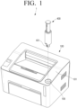
- a pass-through groove 105 through which the toner refill apparatus 400 can be connected to a toner cartridge (not shown) that is mounted within the main body 101, may be formed.
- the pass-through groove 105 may be formed such that the toner refill apparatus 400 can be connected to the toner cartridge from the outside of the main body 101.
- An image forming system 1 is capable of refilling toner to the image forming apparatus 100 by using the toner refill apparatus 400.
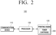
- FIG. 2 is a block diagram illustrating a schematic configuration of the image forming apparatus in FIG. 1 according to an example.
- the processor 130 may identify that it is a first state wherein the toner refill apparatus 400 is not connected. In a case in which the identified voltage value is changed from a first voltage value to a second voltage value, the processor 130 may identify that it is a second state wherein the toner refill apparatus 400 is connected.
- information on availability of the toner refill apparatus 400 may include information on whether the toner refill apparatus 400 is an apparatus that matches authentication information of the image forming apparatus 100 and information on whether the toner refill apparatus 400 is a used toner refill apparatus 400.
- the processor 130 may identify that the toner refill apparatus 400 is an available apparatus. Also, the processor 130 may identify whether the toner refill apparatus 400 is an available apparatus at the same time as whether the toner refill apparatus 400 is connected. If the toner refill apparatus 400 is identified as an available apparatus, the processor 130 may control the toner cartridge 200 such that the toner of the toner refill apparatus 400 is infiltrated into the toner cartridge 200. As an example, the processor 130 may control such that the toner cartridge 200 is rotatively driven by rotating a component of the toner refill apparatus 400, for opening an outlet 401 (refer to FIG. 5 ) of the toner refill apparatus 400 that will be described later.
- the processor 130 may identify that it is a third state wherein the outlet 401 (refer to FIG. 5 ) of the toner refill apparatus 400 is opened.
- the processor 130 may identify that the connected toner refill apparatus 400 is an apparatus that is not available. For example, in order to prevent reuse of the toner refill apparatus 400, in a case in which the toner refill apparatus 400 has already been used, a fifth voltage value may be measured when the toner refill apparatus 400 is connected to the image forming apparatus 100.
- the processor 130 may notify information in this regard to a management server (not shown) or a manager (e.g., a terminal apparatus of a manager).
- the processor 130 may identify the state of the toner refill apparatus 400 as one of the first state, the second state, the third state, the fourth state, and the fifth state based on the identified voltage value.
- the voltage value is not limited to the aforementioned voltage values, and different values may be used depending on manners of implementation.
- a first voltage value, a second voltage value, a third voltage value, a fourth voltage value, and a fifth voltage value may be set such that they are different values from one another, and each of the voltage values has a range that is distanced from one another.
- the processor 130 may identify a state of the toner refill apparatus 400 as one of the first to the fifth state, the disclosure is not limited thereto in that the processor 130 may identify various states of the toner refill apparatus 400. As an example, the processor 130 may identify a state as one of the first to fourth states.
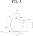
- FIG. 3 is a diagram illustrating a configuration of the printing engine in FIG. 2 according to an example.
- the photosensitive drum 121 On the photosensitive drum 121, an electrostatic latent image is formed.
- the photosensitive drum 121 may be referred to as a photosensitive drum, a photosensitive belt, etc., according to its shape.
- the charging device 122 charges the surface of the photosensitive drum 121 with a homogenous potential.
- the charging device 122 may be implemented as a corona charging device, a charging roller, a charging brush, etc.
- the exposure device 123 changes the surface potential of the photosensitive drum 121 according to information on the image to be printed, and thereby forms an electrostatic latent image on the surface of the photosensitive drum 121.
- the toner cartridge 200 accommodates toner and develops an electrostatic latent image into a visible image by providing toner to the electrostatic latent image formed on the photosensitive drum 121.
- the toner cartridge 200 may include a developing roller 127 that provides toner to the electrostatic latent image.
- An example of a shape and components of the toner cartridge 200 will be described later with reference to FIG. 4 .
- the fusing device 128 fuses the visible image on the recording medium P by applying heat or pressure to the visual image on the recording medium P. By a series of processes as described above, a printing job is completed.
- FIG. 4 is a perspective view of a toner cartridge according to an example.
- the second terminals 251a, 251b, 251c may be electrically connected to the first terminals 151a, 151b, 151c (refer to FIG. 7 ) inside the image forming apparatus 100, when the toner cartridge 200 is mounted on the image forming apparatus 100.
- the second terminals 251a, 251b, 251c may transmit and receive not only signals for communication between the image forming apparatus 100 and the toner cartridge 200, but also signals for communication with a customer replaceable unit monitor (CRUM) apparatus attached to the toner cartridge 200 or the toner refill apparatus 400.
- CRUM customer replaceable unit monitor
- the toner outlet 401 may be provided on the front end of the body 410.
- a discharge shutter 430 may selectively open and close the toner outlet 401.
- the body 410 may include an inner body 411 to accommodate toner, and an outer body 412 disposed on the outside of the inner body 411.
- the plunger 420 may be inserted into the inner body 411 and move in the longitudinal direction A.
- the toner outlet 401 may be connected to the inner body 411.
- the discharge shutter 430 may be installed such that it can independently rotate with respect to the front end of the body 410.
- the discharge shutter 430 may be disposed in a closed position blocking the toner outlet 401.
- the discharge shutter 430 may be disposed in a discharge position wherein the discharge shutter 430 rotates with respect to the body 410 and opens the toner outlet 401.
- the discharge shutter 430 may rotate with respect to the center axis of the toner refill apparatus 400 by rotation of the toner cartridge 200. In an example, the discharge shutter 430 rotates by 180 degrees.
- the toner refill apparatus 400 includes the circuit board 453 for managing information of the toner refill apparatus 400, and fourth terminals 451 (i.e., 451a, 451b, and 451c) for connection with the main body 101.
- the circuit board 453 and the fourth terminals 451 may be provided on the front end of the body 410.
- the fourth terminals 451a, 451b, 451c may be electrically connected to the third terminals 261a, 261b, 261c of the toner cartridge 200, and transmit the information and state of the toner refill apparatus 400 to the main body 101 of the image forming apparatus 100 through the toner cartridge 200.
- the circuit board 453 may be a CRUM part that includes a processor performing at least one of authentication or encrypted data communication with the main body 101.
- the circuit board 453 may include function blocks that are capable of performing various functions for communication, authentication, encryption, etc. with the main body 101.
- the circuit board 453 may be implemented in the form of a chip including a processor or memory, or in the form of a printed circuit board assembly (PBA) on which a chip and circuit elements for implementing various function blocks are mounted.
- PBA printed circuit board assembly
- the fourth terminals 451a, 451b, 451c may have various forms which enable electrical connection with the main body 101, such as a form of a conductive pattern, a form of a modular jack, a form of an elastic terminal, etc.
- the fourth terminals 451 in this example illustrated in FIG. 5 are conductive patterns.
- the fourth terminals 451 may be formed to be exposed to the outside of the body 410.
- the fourth terminals 451 may comprise terminals that become three electrical contacts.
- the fourth terminals 451a, 451b, 451c may comprise a fourth data terminal 451a, a fourth ground terminal 451b, and a fourth state terminal 451c.
- the fourth data terminal 451a may be for transmitting information stored in the memory of the circuit board 453 to the main body 101 of the image forming apparatus 100.
- the fourth state terminal 451c may be for transmitting signals regarding whether the toner refill apparatus 400 is mounted on the toner cartridge 200, and whether the refill operation of the toner refill apparatus 400 has been completed to the main body 101 of the image forming apparatus 100.
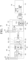
- a closed circuit may be formed by a first resistance R1 (refer to FIG. 7 ) disposed between the fourth ground terminal 451b and the fourth state terminal 451c, and thus it can be identified whether the toner refill apparatus 400 is mounted on the toner cartridge 200.
- the processor 130 may identify whether the toner refill apparatus 400 is connected.
- the toner refill apparatus 400 may include a second resistance R2 (refer to FIG. 7 ) and a fuse 440 for identifying whether the toner refill apparatus 400 has completed a refill operation.
- the toner refill apparatus 400 includes the second resistance R2 of which one end is commonly connected to one end of the first resistance R1 and the fourth ground terminal 451b, and the fuse 440 of which one end is connected to the other end of the second resistance R2, and of which the other end is connected to the fourth state terminal 451c.
- the fuse 440 may be formed to be opened when a refill operation of the toner refill apparatus 400 is completed. As the second resistance R2 disposed in parallel with the first resistance R1 is removed by opening of the fuse 440, it can be identified whether the toner refill apparatus 400 has completed the refill operation.
- the second resistance R2 may be removed by opening of the fuse 440, and accordingly, a voltage value between the first state terminal 151c and the first ground terminal 151b of the main body 101 is changed. Thus, it can be identified whether the toner refill apparatus 400 has completed the refill operation.
- the fuse 440 may include a pair of electrodes 441, 442 that are provided on the outer body 412 and the inner body 411.
- the pair of electrodes 441, 442 may be respectively connected to the fourth state terminal 451c.
- the state of electrical contact of the pair of electrodes 441, 442 may vary according to the position of the plunger 420.
- the state of electrical contact of the pair of electrodes 441, 442 may become an open state when the plunger 420 reaches a position wherein refill of toner is completed.
- the open state of the pair of electrodes 441, 442 will stop a current from flowing.
- an operation lever 443 that is movable in the longitudinal direction A between the outer body 412 and the inner body 411 may be provided.
- a pressing projection 445 that makes the pair of electrodes 441, 442 distanced from each other by pushing the operation lever 443 when a refill operation has been completed may be provided.
- the pressing projection 445 may release the connection between the pair of electrodes 441, 442 by pushing the operation lever 443 according to use of the plunger 420 in the longitudinal direction A.
- the fuse 440 includes the pair of electrodes 441, 442.
- the fuse 440 may be formed in various shapes such that the shape of the fuse 440 is damaged as it melts or is broken when infiltration of toner by the toner refill apparatus 400 is completed, and is not restored again.
- the toner refill apparatus 400 may prevent illegal reuse of the toner refill apparatus 400 by the fuse 440 that is damaged when infiltration of toner is completed.
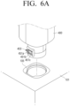
- FIGS. 6A and 6B are diagrams for illustrating a toner refill apparatus that is connected to a toner cartridge through a pass-through part from an exterior of a main body of an image forming apparatus according to an example.
- the toner refill apparatus 400 may be mounted on the toner cartridge 200 through the pass-through groove 105 from the exterior of the main body 101 of the image forming apparatus 100.
- FIG. 6A illustrates a view of the toner refill apparatus 400 from a front side when the toner refill apparatus 400 is coupled to the pass-through groove 105.
- FIG. 6B illustrates a view of the toner refill apparatus 400 from a rear side when the toner refill apparatus 400 is coupled to the pass-through groove 105.
- the toner refill apparatus 400 When the toner refill apparatus 400 is inserted into the pass-through groove 105 from the upper direction of the main body 101, the toner refill apparatus 400 may be mounted on the toner cartridge 200.
- the fourth terminals 451a, 451b, 451c of the toner refill apparatus 400 may be electrically connected to the third terminals 261a, 261b, 261c disposed in the toner cartridge 200.
- the fourth terminals 451a, 451b, 451c of the toner refill apparatus 400 may be electrically connected to the first terminals 151 of the main body 101 through the third terminals 261a, 261b, 261c and the second terminals 251a, 251b, 251c provided on the toner cartridge 200. Accordingly, the toner refill apparatus 400 may be electrically connected to the main body 101 through the toner cartridge 200.
- the toner cartridge 200 and the toner refill apparatus 400 are consumable components that can be attached to or detached from the image forming apparatus 100, and the toner charging device 210 formed on the toner cartridge 200 may connect the toner cartridge 200 and the toner refill apparatus 400 to the main body of the image forming apparatus 100.
- the communication device 110 may further include a fourth resistance R4 formed on the first state terminal 151c to which a reference voltage (VDD) is applied.
- VDD reference voltage
- the processor 130 may control operations of the image forming apparatus 100 based on connection with the toner cartridge 200 mounted on the main body 101, and the toner refill apparatus 400 mounted on the toner cartridge 200.
- the toner cartridge 200 may connect the toner refill apparatus 400 mounted on the toner cartridge 200 to the main body 101 through an identical interface to the toner cartridge 200 mounted on the main body 101.
- the toner cartridge 200 may include the second terminals 251 that are electrically connected to the communication device 110 provided on the main body 101, and the third terminals 261 that are electrically connected to the toner refill apparatus 400 mounted on the toner cartridge 200.
- the toner cartridge 200 may include a circuit board 253 that manages information on the toner cartridge 200, and may transmit information on the state of the toner refill apparatus 400 acquired through the third terminals 261a, 261b, 261c, and information on the toner refill apparatus 400 acquired from the circuit board 453 to the communication device 110.
- the third terminals 261a, 261b, 261c may comprise a plurality of terminals which are three electrical contacts. Each of the three electrical contacts of the second terminals 251a, 251b, 251c may be electrically connected to each of the three electrical contacts of the third terminals 261a, 261b, 261c, respectively, by a flexible cable.
- the circuit board 253 may be disposed on a surface that is opposite to a contact surface on which the second terminals 251a, 251b, 251c that are electrically connected to the main body 101 are formed.
- Each of a plurality of electrical contacts provided on the second terminals 251a, 251b, 251c may respectively be connected to each of a plurality of electrical contacts provided on the third terminals 261a, 261b, 261c in a corresponding manner.
- the state of electrical contact of the pair of electrodes 441, 442 is such that, when the plunger 420 of the toner refill apparatus 400 reaches a specific position which corresponds to a state of completion of toner refill, the fuse 440 may electrically short connection of the fourth state terminal 451c connected with the second resistance R2.
- the toner cartridge 200 may be electrically connected to the toner refill apparatus 400 mounted on the toner cartridge 200 and the main body 101, and may transmit information on the toner refill apparatus 400 and information on the toner cartridge 200 to the communication device 110 through the same interface.
- the image forming apparatus 100 may identify the connection state of the toner refill apparatus 400 and the state of completion of toner refill of the toner refill apparatus 400, etc. by using the state terminals 151c, 251c, 261c, and 451c.
- the communication device 110 of the image forming apparatus 100 may include the first terminals 151a, 151b, 151c that are electrically connected to the second terminals 251a, 251b, 251c of the toner cartridge 200 when the toner cartridge 200 is mounted on the main body 101, and the first state terminal 151c may be electrically connected to the second state terminal 251c.
- the toner cartridge 200 may include the third terminals 261a, 261b, 261c that are electrically connected to the fourth terminals 451a, 451b, 451c of the toner refill apparatus 400 when the toner refill apparatus 400 is connected to the toner cartridge 200.
- the third terminals 261a, 261b, 261c may be connected with the communication device 110 having the first terminals 151a, 151b, 151c through the second terminals 251a, 251b, 251c.
- the communication device 110 may detect whether the toner refill apparatus 400 is connected to the toner cartridge 200 by detecting whether the fourth state terminal 451c, the third state terminal 261c, and the second state terminal 251c are electrically connected.
- the third state terminal 261c and the fourth state terminal 451c are in an open state wherein they are not connected. Accordingly, a current does not flow in a circuit passing through the second state terminal 251c, and thus a first voltage value which is a reference voltage (VDD) is measured at the input port of the communication device 110 including a first state terminal 151c connected with the second state terminal 251c.
- VDD reference voltage
- 3.3V which is a reference voltage (VDD) itself is applied.
- a closed circuit may be formed.
- the closed circuit may include a circuit wherein the first and second resistances R1, R2 connected in parallel, the third resistance R3, and the fourth resistance R4 are connected in series.
- a second voltage value may be measured at the input port of the communication device 110.
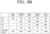
- the resistance value of the first resistance R1 is 5K ⁇
- the resistance value of the second resistance R2 is 1K ⁇
- the resistance value of the third resistance R3 is 20K ⁇
- the resistance value of the fourth resistance R4 is 10K ⁇ , 2.23V, which is a second voltage value, may be applied to the input port of the communication device 110.
- the fourth data terminal 451a of the toner refill apparatus 400 may be connected to the first data terminal 151a through the third data terminal 261a and the second data terminal 251a.
- the communication device 110 may read information on the toner refill apparatus 400 through the circuit board 453 provided on the toner refill apparatus 400.
- Information on the toner refill apparatus 400 may include information for authentication of the toner refill apparatus 400.
- the toner cartridge 200 may include the switch 270 that detects that the toner refill apparatus 400 reached a specific position according to rotation of the toner refill apparatus 400 mounted on the toner cartridge 200.
- the toner cartridge 200 may transmit information on whether the mounted toner refill apparatus 400 reached a specific position according to rotation to the communication device 110 through the first state terminal 151c, based on an operation of the switch 270.
- the contact state of the switch 270 may be changed when the toner refill apparatus 400 reaches a specific position as one component provided on the toner cartridge 200 rotates in association with rotation of the toner refill apparatus 400.
- the switch 270 may be in an electrical open state.
- a voltage of 2.23V which is a second voltage value may be applied to the input port of the communication device 110.
- the switch 270 may be in an electrical short state.
- a determination of whether a state is the third state may be made based on a reference voltage (VDD) and a circuit including the first resistance R1, the second resistance R2, and the fourth resistance R4.
- VDD reference voltage
- a circuit passing through the first state terminal 151c may be a circuit wherein the first and second resistances R1, R2 connected in parallel, and the fourth resistance R4 are connected in series.
- the state of electrical contact of the switch 270 provided on the toner cartridge 200 may be changed from an open state to an electrical short state, and accordingly, a third voltage may be measured at the input port of the communication device 110.
- a voltage of 0.25V may be applied to the input port of the communication device 110.
- the communication device 110 may detect whether the toner refill apparatus 400 rotates based on the change of a voltage at the first state terminal 151c, and may control the image forming apparatus according to the detection result.
- the user may press the plunger 420, and thereby fill the toner accommodating part with toner through the toner cartridge 200.
- Whether infiltration of toner has been completed may be detected by the toner infiltration completion fuse 440.
- a pressing projection 445 may push the operation lever 443, and thereby cause the pair of electrodes 441, 442 to be distanced from each other.
- One of the pair of electrodes 441, 442 may be a fixed electrode, and the other electrode may be an elastic electrode that may elastically be distanced from the fixed electrode.
- whether the state is the fourth state may be identified by a reference voltage (VDD) and a circuit including the first resistance R1 and the fourth resistance R4.
- VDD reference voltage
- a circuit passing through the first state terminal 151c may be a circuit wherein the first resistance R1 and the fourth resistance R4 are connected in series.
- a voltage of 1.1V may be applied to the input port of the communication device 110.
- the communication device 110 may detect whether the toner refill apparatus 400 was used based on the change of a voltage flowing through the first state terminal 151c according to whether refill of toner from the toner refill apparatus 400 is completed, and may control the image forming apparatus according to the detection result.
- the toner refill apparatus 400 may be rotated in an opposite direction to the direction of rotation of the toner refill apparatus 400 after it was mounted on the toner cartridge 200. Accordingly, an inflow shutter (not shown) that rotated in association with rotation of the toner refill apparatus 400 may be restored to its original position.
- a lock of the toner refill apparatus 400 is released as the toner refill apparatus 400 is rotated in an opposite direction to the direction of rotation of the toner refill apparatus 400 after it was mounted on the toner cartridge 200, the user may separate the toner refill apparatus 400 from the toner cartridge 200. Accordingly, a signal of 3.3V may be input again to the input port of the communication device 110.
- the image forming apparatus 100 may identify a state wherein the toner refill apparatus 400 that was used at least once is connected to the image forming apparatus 100 as the fifth state, in order to prevent reuse of the toner refill apparatus 400.
- the fuse 440 of the toner refill apparatus 400 is opened based on use of the toner refill apparatus 400. Accordingly, in the case of the fifth state wherein the toner refill apparatus 400 used once is connected to the image forming apparatus 100, a fifth voltage value may be applied to the input port of the communication device 110.
- the second resistance R2 does not influence the measured voltage value, due to opening of the fuse 440.
- Whether the toner refill apparatus 400 is in the fifth state may be identified by a reference voltage VDD and a circuit including the first resistance R1, the third resistance R3, and the fourth resistance R4.
- a circuit passing through the first state terminal 151c may be a circuit wherein the first resistance R1, the third resistance R3, and the fourth resistance R4 are connected in series.
- a voltage of 2.36V which is a fifth voltage value may be applied to the input port of the communication device 110.
- FIG. 9 is a diagram for illustrating a schematic connection structure among a toner refill apparatus, a toner cartridge, and a main body according to an example.
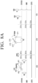
- FIG. 10A is a diagram for illustrating a circuit structure of a toner refill apparatus, a toner cartridge, and a main body according to an example.
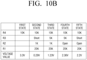
- FIG. 10B is a table illustrating voltage values according to the states of a toner refill apparatus according to an example.
- FIGS. 9 , 10A , and 10B an image forming apparatus 2 is illustrated.
- most of the components of the image forming apparatus 2 are substantially identical to the components of the image forming apparatus 100 illustrated in FIGS. 7 and 8 .
- the toner cartridge 200 may include a third state terminal 261c, a third resistance R3 disposed between the third state terminal 261c, and the switch 280 that is disposed in parallel with the third resistance R3 and selectively connects the second state terminal 251c and the third state terminal 261c.
- One of the pair of electrodes 281, 282 may be a fixed electrode, and the other electrode may be an elastic electrode that may elastically contact or be distanced from the fixed electrode.
- the state of electrical contact of the pair of electrodes 281, 282 may change from an electrical short state to an electrical open state by an operation of the switch 280, when a component that rotates in association with rotation of the toner refill apparatus 400 mounted on the toner cartridge 200 reaches a specific position.
- the third state terminal 261c and the fourth state terminal 451c are in an open state wherein they are not connected. Accordingly, a current does not flow in a circuit passing through the second state terminal 251c, and thus a first voltage value which is a reference voltage (VDD) may be specified at the input port of the communication device 110 having a first state terminal 151c connected with the second state terminal 251c. For example, 3.3V is applied to the input port of the communication device 110.
- VDD reference voltage
- the switch 280 is in an electrical short state.
- whether the state is the second state may be identified by a reference voltage (VDD) and a circuit including the first resistance R1, the second resistance R2, and the fourth resistance R4.
- a circuit passing through the first state terminal 151c may be a circuit wherein the first and second resistances R1, R2 connected in parallel, and the fourth resistance R4 are connected in series.
- a voltage of 0.29V for example, which is a second voltage value may be applied to the input port of the communication device 110.
- a circuit passing through the first state terminal 151c may be a circuit wherein the first and second resistances R1, R2 connected in parallel, the third resistance R3, and the fourth resistance R4 are connected in series.
- a voltage of 1.23V for example, which is a third voltage value may be applied to the input port of the communication device 110.
- the fuse 440 provided on the toner refill apparatus 400 is opened, and the state of electrical contact is changed. Accordingly, a voltage of 2.36V, for example, which is a fourth voltage value may be applied to the input port of the communication device 110.
- the image forming apparatus 2 may determine a state wherein the toner refill apparatus 400 that was used at least once is connected to the image forming apparatus 2 as the fifth state, in order to prevent reuse of the toner refill apparatus 400.
- the fuse 440 of the toner refill apparatus 400 is opened by use. Accordingly, in the case of the fifth state wherein the toner refill apparatus 400 used once is connected to the image forming apparatus 2, a fifth voltage value may be applied to the input port of the communication device 110.
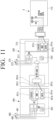
- FIG. 11 is a diagram for illustrating a schematic connection structure among a toner refill apparatus, a toner cartridge, and a main body according to an example.
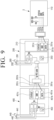
- FIG. 12A is a diagram for illustrating a circuit structure of a toner refill apparatus, a toner cartridge, and a main body according to an example.
- FIG. 12B is a table illustrating voltage values according to the states of a toner refill apparatus according to an example.
Landscapes
- Physics & Mathematics (AREA)
- General Physics & Mathematics (AREA)
- Life Sciences & Earth Sciences (AREA)
- Sustainable Development (AREA)
- Engineering & Computer Science (AREA)
- Computer Vision & Pattern Recognition (AREA)
- Electrophotography Configuration And Component (AREA)
- Control Or Security For Electrophotography (AREA)
Claims (2)
- Appareil de recharge d'encre en poudre (400), comprenant :une bouteille pour conserver une encre en poudre ;une carte de circuit imprimé (453) qui est disposée sur la bouteille, et pour stocker des informations relatives à l'appareil et l'historique d'utilisation de l'appareil de recharge d'encre en poudre (400) ;une pluralité de bornes pour communiquer avec un dispositif de communication d'un appareil de formation d'images (100) ; etun élément de circuit pour faire varier, en fonction de l'infiltration de l'encre en poudre conservée dans la bouteille en cours d'achèvement, une valeur de résistance entre une première borne (151) et une seconde borne (251) parmi la pluralité de bornes,dans lequel l'élément de circuit comprend :une première résistance (R1) qui est disposée entre une borne de terre (451b) et une borne d'état (451c) ;caractérisé en ce que l'élément de circuit comprend une seconde résistance (R2) dont une extrémité est communément connectée à une extrémité de la première résistance (R1) et à la borne de terre (452b) ; etun fusible (440) dont une extrémité est connectée à l'autre extrémité de la seconde résistance (R2) et dont l'autre extrémité est connectée à la borne d'état (451c).
- Appareil de recharge d'encre en poudre (400) selon la revendication 1, dans lequel le fusible (440) s'ouvre lorsque l'infiltration de l'encre en poudre est achevée.
Applications Claiming Priority (2)
| Application Number | Priority Date | Filing Date | Title |
|---|---|---|---|
| KR1020190005937A KR102673428B1 (ko) | 2019-01-16 | 2019-01-16 | 토너 리필 장치의 연결 상태를 판단하기 위한 방법 |
| PCT/US2019/067896 WO2020149984A1 (fr) | 2019-01-16 | 2019-12-20 | Procédé de détermination du statut de connexion d'un dispositif de recharge de toner |
Publications (3)
| Publication Number | Publication Date |
|---|---|
| EP3864468A1 EP3864468A1 (fr) | 2021-08-18 |
| EP3864468A4 EP3864468A4 (fr) | 2022-11-23 |
| EP3864468B1 true EP3864468B1 (fr) | 2024-07-03 |
Family
ID=71614464
Family Applications (1)
| Application Number | Title | Priority Date | Filing Date |
|---|---|---|---|
| EP19910525.5A Active EP3864468B1 (fr) | 2019-01-16 | 2019-12-20 | Procédé de détermination du statut de connexion d'un dispositif de recharge de toner |
Country Status (6)
| Country | Link |
|---|---|
| US (1) | US11537063B2 (fr) |
| EP (1) | EP3864468B1 (fr) |
| KR (1) | KR102673428B1 (fr) |
| CN (1) | CN113168126B (fr) |
| BR (1) | BR112021013027A2 (fr) |
| WO (1) | WO2020149984A1 (fr) |
Families Citing this family (1)
| Publication number | Priority date | Publication date | Assignee | Title |
|---|---|---|---|---|
| KR20200135026A (ko) * | 2019-05-24 | 2020-12-02 | 휴렛-팩커드 디벨롭먼트 컴퍼니, 엘.피. | 토너 리필 중 비정상 동작의 처리 |
Family Cites Families (22)
| Publication number | Priority date | Publication date | Assignee | Title |
|---|---|---|---|---|
| US5075724A (en) * | 1988-08-26 | 1991-12-24 | Minolta Camera Kabushiki Kaisha | System for recognizing interchangeable articles |
| JPH06149047A (ja) | 1992-11-10 | 1994-05-27 | Fuji Xerox Co Ltd | トナーカートリッジ用トナー供給装置 |
| US6065824A (en) * | 1994-12-22 | 2000-05-23 | Hewlett-Packard Company | Method and apparatus for storing information on a replaceable ink container |
| KR100366646B1 (ko) * | 1998-04-25 | 2003-01-06 | 삼성전자 주식회사 | 메모리를 장착한 현상제 유니트 및 그것을 이용한 화상형성장치의 작동방법 |
| JP3447595B2 (ja) | 1998-12-22 | 2003-09-16 | シャープ株式会社 | 画像形成装置 |
| SG117422A1 (en) | 2002-09-11 | 2005-12-29 | Inke Pte Ltd | Refill station |
| JP4205531B2 (ja) | 2003-08-25 | 2009-01-07 | 株式会社リコー | 搬送装置及び画像形成装置 |
| KR100553897B1 (ko) | 2003-10-31 | 2006-02-24 | 삼성전자주식회사 | 메모리를 이용한 화상형성장치의 소모품 관리 장치 |
| JP4343074B2 (ja) | 2004-03-19 | 2009-10-14 | 株式会社リコー | 容器収納装置、該容器収納装置を備えた搬送装置及び画像形成装置 |
| US20060279127A1 (en) | 2005-06-09 | 2006-12-14 | Cronin John E | Apparatus including a selective interface system between two sub-components |
| KR101198771B1 (ko) * | 2008-01-09 | 2012-11-12 | 삼성전자주식회사 | 화상형성장치 및 그 제어방법 |
| JP5434173B2 (ja) | 2009-03-18 | 2014-03-05 | 株式会社リコー | 画像形成装置、及び画像形成方法 |
| US8762716B2 (en) | 2009-10-15 | 2014-06-24 | Samsung Electronics Co., Ltd. | Image forming apparatus |
| ES2711352T3 (es) * | 2010-06-11 | 2019-05-03 | Ricoh Co Ltd | Dispositivo de almacenamiento de información, dispositivo extraíble, contenedor de revelador y aparato de formación de imágenes |
| JP4843112B1 (ja) | 2010-06-11 | 2011-12-21 | 株式会社リコー | 着脱可能装置、現像剤容器、及び、画像形成装置 |
| JP5429638B2 (ja) * | 2010-06-28 | 2014-02-26 | 株式会社リコー | 画像形成装置及び画像形成装置の電源制御方法 |
| US8879953B2 (en) * | 2012-06-25 | 2014-11-04 | Lexmark International, Inc. | Retainer assembly having positioning features for processing circuitry used within an image forming device supply item |
| JP6074987B2 (ja) | 2012-09-28 | 2017-02-08 | ブラザー工業株式会社 | リフィル検知機能を有する画像形成装置、及びリフィル検知方法 |
| US9227417B2 (en) * | 2013-03-15 | 2016-01-05 | Ologn Technologies Ag | Systems, methods and apparatuses for authorized use and refill of a printer cartridge |
| CA2928848C (fr) * | 2013-03-15 | 2021-12-14 | Ologn Technologies Ag | Systemes, methodes et appareils pour utilisation autorisee et recharge d'une cartouche d'imprimante |
| JP6488733B2 (ja) * | 2015-02-02 | 2019-03-27 | 株式会社ソシオネクスト | 電源回路、充電回路、充電システム、給電方法及び充電方法 |
| JP6398916B2 (ja) * | 2015-08-31 | 2018-10-03 | 京セラドキュメントソリューションズ株式会社 | 電子機器及び画像形成装置 |
-
2019
- 2019-01-16 KR KR1020190005937A patent/KR102673428B1/ko active Active
- 2019-12-20 WO PCT/US2019/067896 patent/WO2020149984A1/fr not_active Ceased
- 2019-12-20 EP EP19910525.5A patent/EP3864468B1/fr active Active
- 2019-12-20 BR BR112021013027-6A patent/BR112021013027A2/pt not_active IP Right Cessation
- 2019-12-20 CN CN201980079509.0A patent/CN113168126B/zh active Active
- 2019-12-20 US US17/312,513 patent/US11537063B2/en active Active
Also Published As
| Publication number | Publication date |
|---|---|
| EP3864468A1 (fr) | 2021-08-18 |
| WO2020149984A1 (fr) | 2020-07-23 |
| CN113168126B (zh) | 2024-03-01 |
| US20220057728A1 (en) | 2022-02-24 |
| KR20200089181A (ko) | 2020-07-24 |
| EP3864468A4 (fr) | 2022-11-23 |
| US11537063B2 (en) | 2022-12-27 |
| KR102673428B1 (ko) | 2024-06-07 |
| CN113168126A (zh) | 2021-07-23 |
| BR112021013027A2 (pt) | 2021-09-21 |
Similar Documents
| Publication | Publication Date | Title |
|---|---|---|
| EP3977209B1 (fr) | Cartouche de développement | |
| JP2016197162A (ja) | カートリッジ及び画像形成装置 | |
| JP7413798B2 (ja) | 画像形成装置、画像形成システム、画像形成装置の制御方法及びプログラム | |
| US11892781B2 (en) | Method for error handling in the toner refill process | |
| US12174556B2 (en) | Toner refill control of image forming apparatus | |
| JP7413799B2 (ja) | 画像形成装置、画像形成システム、画像形成装置の制御方法及びプログラム | |
| EP3762785B1 (fr) | Structure de verrouillage sélectif d'un obturateur d'entrée de toner | |
| EP3077901B1 (fr) | Système d'imprimante réseau | |
| EP2914437B1 (fr) | Système d'imprimante réseau | |
| EP3864468B1 (fr) | Procédé de détermination du statut de connexion d'un dispositif de recharge de toner | |
| EP2600203A2 (fr) | Appareil électronique et appareil de formation d'image | |
| EP3765917B1 (fr) | Cartouche de recharge de toner reliée à un corps principal par l'intermédiaire d'une interface entre une cartouche de développement et un corps principal | |
| JP2001083859A (ja) | 画像形成装置及びそのカートリッジ | |
| KR20200143115A (ko) | 토너 리필 카트리지에서의 토너 주입량 검출 | |
| EP3077900B1 (fr) | Système d'imprimante réseau | |
| JP7447511B2 (ja) | 画像形成装置および画像形成システム | |
| JP2006053581A (ja) | 画像形成装置及びそのカートリッジ |
Legal Events
| Date | Code | Title | Description |
|---|---|---|---|
| STAA | Information on the status of an ep patent application or granted ep patent |
Free format text: STATUS: THE INTERNATIONAL PUBLICATION HAS BEEN MADE |
|
| PUAI | Public reference made under article 153(3) epc to a published international application that has entered the european phase |
Free format text: ORIGINAL CODE: 0009012 |
|
| STAA | Information on the status of an ep patent application or granted ep patent |
Free format text: STATUS: REQUEST FOR EXAMINATION WAS MADE |
|
| 17P | Request for examination filed |
Effective date: 20210512 |
|
| AK | Designated contracting states |
Kind code of ref document: A1 Designated state(s): AL AT BE BG CH CY CZ DE DK EE ES FI FR GB GR HR HU IE IS IT LI LT LU LV MC MK MT NL NO PL PT RO RS SE SI SK SM TR |
|
| DAV | Request for validation of the european patent (deleted) | ||
| DAX | Request for extension of the european patent (deleted) | ||
| RIC1 | Information provided on ipc code assigned before grant |
Ipc: G03G 21/16 20060101ALI20220615BHEP Ipc: G03G 15/00 20060101AFI20220615BHEP |
|
| A4 | Supplementary search report drawn up and despatched |
Effective date: 20221026 |
|
| RIC1 | Information provided on ipc code assigned before grant |
Ipc: G03G 21/16 20060101ALI20221020BHEP Ipc: G03G 15/00 20060101AFI20221020BHEP |
|
| GRAP | Despatch of communication of intention to grant a patent |
Free format text: ORIGINAL CODE: EPIDOSNIGR1 |
|
| STAA | Information on the status of an ep patent application or granted ep patent |
Free format text: STATUS: GRANT OF PATENT IS INTENDED |
|
| INTG | Intention to grant announced |
Effective date: 20240419 |
|
| GRAS | Grant fee paid |
Free format text: ORIGINAL CODE: EPIDOSNIGR3 |
|
| GRAA | (expected) grant |
Free format text: ORIGINAL CODE: 0009210 |
|
| STAA | Information on the status of an ep patent application or granted ep patent |
Free format text: STATUS: THE PATENT HAS BEEN GRANTED |
|
| AK | Designated contracting states |
Kind code of ref document: B1 Designated state(s): AL AT BE BG CH CY CZ DE DK EE ES FI FR GB GR HR HU IE IS IT LI LT LU LV MC MK MT NL NO PL PT RO RS SE SI SK SM TR |
|
| REG | Reference to a national code |
Ref country code: CH Ref legal event code: EP |
|
| REG | Reference to a national code |
Ref country code: DE Ref legal event code: R096 Ref document number: 602019054810 Country of ref document: DE |
|
| REG | Reference to a national code |
Ref country code: LT Ref legal event code: MG9D |
|
| REG | Reference to a national code |
Ref country code: NL Ref legal event code: MP Effective date: 20240703 |
|
| PG25 | Lapsed in a contracting state [announced via postgrant information from national office to epo] |
Ref country code: PT Free format text: LAPSE BECAUSE OF FAILURE TO SUBMIT A TRANSLATION OF THE DESCRIPTION OR TO PAY THE FEE WITHIN THE PRESCRIBED TIME-LIMIT Effective date: 20241104 |
|
| REG | Reference to a national code |
Ref country code: AT Ref legal event code: MK05 Ref document number: 1700443 Country of ref document: AT Kind code of ref document: T Effective date: 20240703 |
|
| PG25 | Lapsed in a contracting state [announced via postgrant information from national office to epo] |
Ref country code: NL Free format text: LAPSE BECAUSE OF FAILURE TO SUBMIT A TRANSLATION OF THE DESCRIPTION OR TO PAY THE FEE WITHIN THE PRESCRIBED TIME-LIMIT Effective date: 20240703 |
|
| PG25 | Lapsed in a contracting state [announced via postgrant information from national office to epo] |
Ref country code: PT Free format text: LAPSE BECAUSE OF FAILURE TO SUBMIT A TRANSLATION OF THE DESCRIPTION OR TO PAY THE FEE WITHIN THE PRESCRIBED TIME-LIMIT Effective date: 20241104 Ref country code: NL Free format text: LAPSE BECAUSE OF FAILURE TO SUBMIT A TRANSLATION OF THE DESCRIPTION OR TO PAY THE FEE WITHIN THE PRESCRIBED TIME-LIMIT Effective date: 20240703 |
|
| PG25 | Lapsed in a contracting state [announced via postgrant information from national office to epo] |
Ref country code: NO Free format text: LAPSE BECAUSE OF FAILURE TO SUBMIT A TRANSLATION OF THE DESCRIPTION OR TO PAY THE FEE WITHIN THE PRESCRIBED TIME-LIMIT Effective date: 20241003 |
|
| PG25 | Lapsed in a contracting state [announced via postgrant information from national office to epo] |
Ref country code: FI Free format text: LAPSE BECAUSE OF FAILURE TO SUBMIT A TRANSLATION OF THE DESCRIPTION OR TO PAY THE FEE WITHIN THE PRESCRIBED TIME-LIMIT Effective date: 20240703 Ref country code: GR Free format text: LAPSE BECAUSE OF FAILURE TO SUBMIT A TRANSLATION OF THE DESCRIPTION OR TO PAY THE FEE WITHIN THE PRESCRIBED TIME-LIMIT Effective date: 20241004 Ref country code: PL Free format text: LAPSE BECAUSE OF FAILURE TO SUBMIT A TRANSLATION OF THE DESCRIPTION OR TO PAY THE FEE WITHIN THE PRESCRIBED TIME-LIMIT Effective date: 20240703 |
|
| PG25 | Lapsed in a contracting state [announced via postgrant information from national office to epo] |
Ref country code: BG Free format text: LAPSE BECAUSE OF FAILURE TO SUBMIT A TRANSLATION OF THE DESCRIPTION OR TO PAY THE FEE WITHIN THE PRESCRIBED TIME-LIMIT Effective date: 20240703 |
|
| PG25 | Lapsed in a contracting state [announced via postgrant information from national office to epo] |
Ref country code: LV Free format text: LAPSE BECAUSE OF FAILURE TO SUBMIT A TRANSLATION OF THE DESCRIPTION OR TO PAY THE FEE WITHIN THE PRESCRIBED TIME-LIMIT Effective date: 20240703 |
|
| PG25 | Lapsed in a contracting state [announced via postgrant information from national office to epo] |
Ref country code: IS Free format text: LAPSE BECAUSE OF FAILURE TO SUBMIT A TRANSLATION OF THE DESCRIPTION OR TO PAY THE FEE WITHIN THE PRESCRIBED TIME-LIMIT Effective date: 20241103 Ref country code: AT Free format text: LAPSE BECAUSE OF FAILURE TO SUBMIT A TRANSLATION OF THE DESCRIPTION OR TO PAY THE FEE WITHIN THE PRESCRIBED TIME-LIMIT Effective date: 20240703 |
|
| PG25 | Lapsed in a contracting state [announced via postgrant information from national office to epo] |
Ref country code: CZ Free format text: LAPSE BECAUSE OF FAILURE TO SUBMIT A TRANSLATION OF THE DESCRIPTION OR TO PAY THE FEE WITHIN THE PRESCRIBED TIME-LIMIT Effective date: 20240703 Ref country code: HR Free format text: LAPSE BECAUSE OF FAILURE TO SUBMIT A TRANSLATION OF THE DESCRIPTION OR TO PAY THE FEE WITHIN THE PRESCRIBED TIME-LIMIT Effective date: 20240703 |
|
| PG25 | Lapsed in a contracting state [announced via postgrant information from national office to epo] |
Ref country code: ES Free format text: LAPSE BECAUSE OF FAILURE TO SUBMIT A TRANSLATION OF THE DESCRIPTION OR TO PAY THE FEE WITHIN THE PRESCRIBED TIME-LIMIT Effective date: 20240703 Ref country code: RS Free format text: LAPSE BECAUSE OF FAILURE TO SUBMIT A TRANSLATION OF THE DESCRIPTION OR TO PAY THE FEE WITHIN THE PRESCRIBED TIME-LIMIT Effective date: 20241003 |
|
| PG25 | Lapsed in a contracting state [announced via postgrant information from national office to epo] |
Ref country code: RS Free format text: LAPSE BECAUSE OF FAILURE TO SUBMIT A TRANSLATION OF THE DESCRIPTION OR TO PAY THE FEE WITHIN THE PRESCRIBED TIME-LIMIT Effective date: 20241003 Ref country code: PL Free format text: LAPSE BECAUSE OF FAILURE TO SUBMIT A TRANSLATION OF THE DESCRIPTION OR TO PAY THE FEE WITHIN THE PRESCRIBED TIME-LIMIT Effective date: 20240703 Ref country code: NO Free format text: LAPSE BECAUSE OF FAILURE TO SUBMIT A TRANSLATION OF THE DESCRIPTION OR TO PAY THE FEE WITHIN THE PRESCRIBED TIME-LIMIT Effective date: 20241003 Ref country code: LV Free format text: LAPSE BECAUSE OF FAILURE TO SUBMIT A TRANSLATION OF THE DESCRIPTION OR TO PAY THE FEE WITHIN THE PRESCRIBED TIME-LIMIT Effective date: 20240703 Ref country code: IS Free format text: LAPSE BECAUSE OF FAILURE TO SUBMIT A TRANSLATION OF THE DESCRIPTION OR TO PAY THE FEE WITHIN THE PRESCRIBED TIME-LIMIT Effective date: 20241103 Ref country code: HR Free format text: LAPSE BECAUSE OF FAILURE TO SUBMIT A TRANSLATION OF THE DESCRIPTION OR TO PAY THE FEE WITHIN THE PRESCRIBED TIME-LIMIT Effective date: 20240703 Ref country code: GR Free format text: LAPSE BECAUSE OF FAILURE TO SUBMIT A TRANSLATION OF THE DESCRIPTION OR TO PAY THE FEE WITHIN THE PRESCRIBED TIME-LIMIT Effective date: 20241004 Ref country code: FI Free format text: LAPSE BECAUSE OF FAILURE TO SUBMIT A TRANSLATION OF THE DESCRIPTION OR TO PAY THE FEE WITHIN THE PRESCRIBED TIME-LIMIT Effective date: 20240703 Ref country code: ES Free format text: LAPSE BECAUSE OF FAILURE TO SUBMIT A TRANSLATION OF THE DESCRIPTION OR TO PAY THE FEE WITHIN THE PRESCRIBED TIME-LIMIT Effective date: 20240703 Ref country code: CZ Free format text: LAPSE BECAUSE OF FAILURE TO SUBMIT A TRANSLATION OF THE DESCRIPTION OR TO PAY THE FEE WITHIN THE PRESCRIBED TIME-LIMIT Effective date: 20240703 Ref country code: BG Free format text: LAPSE BECAUSE OF FAILURE TO SUBMIT A TRANSLATION OF THE DESCRIPTION OR TO PAY THE FEE WITHIN THE PRESCRIBED TIME-LIMIT Effective date: 20240703 Ref country code: AT Free format text: LAPSE BECAUSE OF FAILURE TO SUBMIT A TRANSLATION OF THE DESCRIPTION OR TO PAY THE FEE WITHIN THE PRESCRIBED TIME-LIMIT Effective date: 20240703 |
|
| REG | Reference to a national code |
Ref country code: DE Ref legal event code: R097 Ref document number: 602019054810 Country of ref document: DE |
|
| PG25 | Lapsed in a contracting state [announced via postgrant information from national office to epo] |
Ref country code: DK Free format text: LAPSE BECAUSE OF FAILURE TO SUBMIT A TRANSLATION OF THE DESCRIPTION OR TO PAY THE FEE WITHIN THE PRESCRIBED TIME-LIMIT Effective date: 20240703 Ref country code: RO Free format text: LAPSE BECAUSE OF FAILURE TO SUBMIT A TRANSLATION OF THE DESCRIPTION OR TO PAY THE FEE WITHIN THE PRESCRIBED TIME-LIMIT Effective date: 20240703 Ref country code: SM Free format text: LAPSE BECAUSE OF FAILURE TO SUBMIT A TRANSLATION OF THE DESCRIPTION OR TO PAY THE FEE WITHIN THE PRESCRIBED TIME-LIMIT Effective date: 20240703 |
|
| PG25 | Lapsed in a contracting state [announced via postgrant information from national office to epo] |
Ref country code: EE Free format text: LAPSE BECAUSE OF FAILURE TO SUBMIT A TRANSLATION OF THE DESCRIPTION OR TO PAY THE FEE WITHIN THE PRESCRIBED TIME-LIMIT Effective date: 20240703 |
|
| PG25 | Lapsed in a contracting state [announced via postgrant information from national office to epo] |
Ref country code: SK Free format text: LAPSE BECAUSE OF FAILURE TO SUBMIT A TRANSLATION OF THE DESCRIPTION OR TO PAY THE FEE WITHIN THE PRESCRIBED TIME-LIMIT Effective date: 20240703 Ref country code: IT Free format text: LAPSE BECAUSE OF FAILURE TO SUBMIT A TRANSLATION OF THE DESCRIPTION OR TO PAY THE FEE WITHIN THE PRESCRIBED TIME-LIMIT Effective date: 20240703 |
|
| PLBE | No opposition filed within time limit |
Free format text: ORIGINAL CODE: 0009261 |
|
| STAA | Information on the status of an ep patent application or granted ep patent |
Free format text: STATUS: NO OPPOSITION FILED WITHIN TIME LIMIT |
|
| 26N | No opposition filed |
Effective date: 20250404 |
|
| PG25 | Lapsed in a contracting state [announced via postgrant information from national office to epo] |
Ref country code: MC Free format text: LAPSE BECAUSE OF FAILURE TO SUBMIT A TRANSLATION OF THE DESCRIPTION OR TO PAY THE FEE WITHIN THE PRESCRIBED TIME-LIMIT Effective date: 20240703 |
|
| REG | Reference to a national code |
Ref country code: CH Ref legal event code: PL |
|
| PG25 | Lapsed in a contracting state [announced via postgrant information from national office to epo] |
Ref country code: LU Free format text: LAPSE BECAUSE OF NON-PAYMENT OF DUE FEES Effective date: 20241220 |
|
| GBPC | Gb: european patent ceased through non-payment of renewal fee |
Effective date: 20241220 |
|
| PG25 | Lapsed in a contracting state [announced via postgrant information from national office to epo] |
Ref country code: SE Free format text: LAPSE BECAUSE OF FAILURE TO SUBMIT A TRANSLATION OF THE DESCRIPTION OR TO PAY THE FEE WITHIN THE PRESCRIBED TIME-LIMIT Effective date: 20240703 |
|
| REG | Reference to a national code |
Ref country code: BE Ref legal event code: MM Effective date: 20241231 |
|
| PG25 | Lapsed in a contracting state [announced via postgrant information from national office to epo] |
Ref country code: BE Free format text: LAPSE BECAUSE OF NON-PAYMENT OF DUE FEES Effective date: 20241231 Ref country code: GB Free format text: LAPSE BECAUSE OF NON-PAYMENT OF DUE FEES Effective date: 20241220 |
|
| PG25 | Lapsed in a contracting state [announced via postgrant information from national office to epo] |
Ref country code: FR Free format text: LAPSE BECAUSE OF NON-PAYMENT OF DUE FEES Effective date: 20241231 |
|
| PG25 | Lapsed in a contracting state [announced via postgrant information from national office to epo] |
Ref country code: CH Free format text: LAPSE BECAUSE OF NON-PAYMENT OF DUE FEES Effective date: 20241231 |
|
| PG25 | Lapsed in a contracting state [announced via postgrant information from national office to epo] |
Ref country code: IE Free format text: LAPSE BECAUSE OF NON-PAYMENT OF DUE FEES Effective date: 20241220 |
|
| PGFP | Annual fee paid to national office [announced via postgrant information from national office to epo] |
Ref country code: DE Payment date: 20251126 Year of fee payment: 7 |