EP3864904B1 - Verfahren und vorrichtung zur bestimmung physikalischer uplink-kanalleistungssteuerparameterwerte zur verwendung nach einer strahlausfallwiederherstellung - Google Patents
Verfahren und vorrichtung zur bestimmung physikalischer uplink-kanalleistungssteuerparameterwerte zur verwendung nach einer strahlausfallwiederherstellung Download PDFInfo
- Publication number
- EP3864904B1 EP3864904B1 EP19790824.7A EP19790824A EP3864904B1 EP 3864904 B1 EP3864904 B1 EP 3864904B1 EP 19790824 A EP19790824 A EP 19790824A EP 3864904 B1 EP3864904 B1 EP 3864904B1
- Authority
- EP
- European Patent Office
- Prior art keywords
- spatial relation
- power control
- reference signal
- physical uplink
- uplink
- Prior art date
- Legal status (The legal status is an assumption and is not a legal conclusion. Google has not performed a legal analysis and makes no representation as to the accuracy of the status listed.)
- Active
Links
Images


Classifications
-
- H—ELECTRICITY
- H04—ELECTRIC COMMUNICATION TECHNIQUE
- H04B—TRANSMISSION
- H04B7/00—Radio transmission systems, i.e. using radiation field
- H04B7/02—Diversity systems; Multi-antenna system, i.e. transmission or reception using multiple antennas
- H04B7/04—Diversity systems; Multi-antenna system, i.e. transmission or reception using multiple antennas using two or more spaced independent antennas
- H04B7/06—Diversity systems; Multi-antenna system, i.e. transmission or reception using multiple antennas using two or more spaced independent antennas at the transmitting station
- H04B7/0686—Hybrid systems, i.e. switching and simultaneous transmission
- H04B7/0695—Hybrid systems, i.e. switching and simultaneous transmission using beam selection
- H04B7/06952—Selecting one or more beams from a plurality of beams, e.g. beam training, management or sweeping
- H04B7/06964—Re-selection of one or more beams after beam failure
-
- H—ELECTRICITY
- H04—ELECTRIC COMMUNICATION TECHNIQUE
- H04B—TRANSMISSION
- H04B7/00—Radio transmission systems, i.e. using radiation field
- H04B7/02—Diversity systems; Multi-antenna system, i.e. transmission or reception using multiple antennas
- H04B7/04—Diversity systems; Multi-antenna system, i.e. transmission or reception using multiple antennas using two or more spaced independent antennas
- H04B7/08—Diversity systems; Multi-antenna system, i.e. transmission or reception using multiple antennas using two or more spaced independent antennas at the receiving station
- H04B7/0868—Hybrid systems, i.e. switching and combining
- H04B7/088—Hybrid systems, i.e. switching and combining using beam selection
-
- H—ELECTRICITY
- H04—ELECTRIC COMMUNICATION TECHNIQUE
- H04L—TRANSMISSION OF DIGITAL INFORMATION, e.g. TELEGRAPHIC COMMUNICATION
- H04L5/00—Arrangements affording multiple use of the transmission path
- H04L5/003—Arrangements for allocating sub-channels of the transmission path
- H04L5/0048—Allocation of pilot signals, i.e. of signals known to the receiver
- H04L5/0051—Allocation of pilot signals, i.e. of signals known to the receiver of dedicated pilots, i.e. pilots destined for a single user or terminal
-
- H—ELECTRICITY
- H04—ELECTRIC COMMUNICATION TECHNIQUE
- H04W—WIRELESS COMMUNICATION NETWORKS
- H04W52/00—Power management, e.g. Transmission Power Control [TPC] or power classes
- H04W52/04—Transmission power control [TPC]
- H04W52/06—TPC algorithms
- H04W52/08—Closed loop power control
-
- H—ELECTRICITY
- H04—ELECTRIC COMMUNICATION TECHNIQUE
- H04W—WIRELESS COMMUNICATION NETWORKS
- H04W52/00—Power management, e.g. Transmission Power Control [TPC] or power classes
- H04W52/04—Transmission power control [TPC]
- H04W52/06—TPC algorithms
- H04W52/10—Open loop power control
-
- H—ELECTRICITY
- H04—ELECTRIC COMMUNICATION TECHNIQUE
- H04W—WIRELESS COMMUNICATION NETWORKS
- H04W52/00—Power management, e.g. Transmission Power Control [TPC] or power classes
- H04W52/04—Transmission power control [TPC]
- H04W52/06—TPC algorithms
- H04W52/14—Separate analysis of uplink or downlink
- H04W52/146—Uplink power control
-
- H—ELECTRICITY
- H04—ELECTRIC COMMUNICATION TECHNIQUE
- H04W—WIRELESS COMMUNICATION NETWORKS
- H04W52/00—Power management, e.g. Transmission Power Control [TPC] or power classes
- H04W52/04—Transmission power control [TPC]
- H04W52/18—TPC being performed according to specific parameters
- H04W52/22—TPC being performed according to specific parameters taking into account previous information or commands
- H04W52/228—TPC being performed according to specific parameters taking into account previous information or commands using past power values or information
-
- H—ELECTRICITY
- H04—ELECTRIC COMMUNICATION TECHNIQUE
- H04W—WIRELESS COMMUNICATION NETWORKS
- H04W52/00—Power management, e.g. Transmission Power Control [TPC] or power classes
- H04W52/04—Transmission power control [TPC]
- H04W52/30—Transmission power control [TPC] using constraints in the total amount of available transmission power
- H04W52/32—TPC of broadcast or control channels
- H04W52/325—Power control of control or pilot channels
-
- H—ELECTRICITY
- H04—ELECTRIC COMMUNICATION TECHNIQUE
- H04W—WIRELESS COMMUNICATION NETWORKS
- H04W52/00—Power management, e.g. Transmission Power Control [TPC] or power classes
- H04W52/04—Transmission power control [TPC]
- H04W52/30—Transmission power control [TPC] using constraints in the total amount of available transmission power
- H04W52/36—Transmission power control [TPC] using constraints in the total amount of available transmission power with a discrete range or set of values, e.g. step size, ramping or offsets
-
- H—ELECTRICITY
- H04—ELECTRIC COMMUNICATION TECHNIQUE
- H04W—WIRELESS COMMUNICATION NETWORKS
- H04W52/00—Power management, e.g. Transmission Power Control [TPC] or power classes
- H04W52/04—Transmission power control [TPC]
- H04W52/38—TPC being performed in particular situations
- H04W52/48—TPC being performed in particular situations during retransmission after error or non-acknowledgment
-
- H—ELECTRICITY
- H04—ELECTRIC COMMUNICATION TECHNIQUE
- H04W—WIRELESS COMMUNICATION NETWORKS
- H04W52/00—Power management, e.g. Transmission Power Control [TPC] or power classes
- H04W52/04—Transmission power control [TPC]
- H04W52/38—TPC being performed in particular situations
- H04W52/50—TPC being performed in particular situations at the moment of starting communication in a multiple access environment
-
- H—ELECTRICITY
- H04—ELECTRIC COMMUNICATION TECHNIQUE
- H04W—WIRELESS COMMUNICATION NETWORKS
- H04W72/00—Local resource management
- H04W72/04—Wireless resource allocation
- H04W72/044—Wireless resource allocation based on the type of the allocated resource
- H04W72/046—Wireless resource allocation based on the type of the allocated resource the resource being in the space domain, e.g. beams
-
- H—ELECTRICITY
- H04—ELECTRIC COMMUNICATION TECHNIQUE
- H04W—WIRELESS COMMUNICATION NETWORKS
- H04W72/00—Local resource management
- H04W72/20—Control channels or signalling for resource management
- H04W72/23—Control channels or signalling for resource management in the downlink direction of a wireless link, i.e. towards a terminal
-
- H—ELECTRICITY
- H04—ELECTRIC COMMUNICATION TECHNIQUE
- H04W—WIRELESS COMMUNICATION NETWORKS
- H04W74/00—Wireless channel access
- H04W74/08—Non-scheduled access, e.g. ALOHA
- H04W74/0866—Non-scheduled access, e.g. ALOHA using a dedicated channel for access
-
- H—ELECTRICITY
- H04—ELECTRIC COMMUNICATION TECHNIQUE
- H04W—WIRELESS COMMUNICATION NETWORKS
- H04W74/00—Wireless channel access
- H04W74/08—Non-scheduled access, e.g. ALOHA
- H04W74/0833—Random access procedures, e.g. with 4-step access
-
- H—ELECTRICITY
- H04—ELECTRIC COMMUNICATION TECHNIQUE
- H04W—WIRELESS COMMUNICATION NETWORKS
- H04W74/00—Wireless channel access
- H04W74/08—Non-scheduled access, e.g. ALOHA
- H04W74/0833—Random access procedures, e.g. with 4-step access
- H04W74/0838—Random access procedures, e.g. with 4-step access using contention-free random access [CFRA]
-
- H—ELECTRICITY
- H04—ELECTRIC COMMUNICATION TECHNIQUE
- H04W—WIRELESS COMMUNICATION NETWORKS
- H04W76/00—Connection management
- H04W76/10—Connection setup
- H04W76/19—Connection re-establishment
Definitions
- the present disclosure is directed to a method and apparatus for determining physical uplink channel power control parameter values for use after a beam failure recovery, including whether to use a default power control parameter value or a power control parameter value associated with one of a set of previously known uplink spatial relation configurations.
- NR new radio access technology
- LTE Long Term Evolution
- UMTS Universal Mobile Telecommunications Service
- GSM Global System for Mobile Communication
- EDGE Enhanced Data GSM Environment
- the distance between the user equipment and the access point can vary.
- the varying distance can affect the amount of attenuation that a signal may experience between the time that the signal is transmitted to the time that the signal is ultimately received. While at least one factor that can contribute to an amount of signal attenuation can be related to distance, it is possible that other factors, including environmental factors, may also impact the power level of a signal when the signal is received at its intended destination.
- the relative power levels being used by the user equipment in communicating with the network via the access point using a wireless signal can be adjusted, as needed.
- the desired power control adjustment state value there can be a delay in determining the desired power control adjustment state value, where often in a closed loop environment, through an iterative process, where the amount for the power to be adjusted at the signal's source can be updated until the desired power level is received at the signal's destination. As conditions between the transmitter and the receiver change, the amount of adjustment can be further updated to match the more recent operating conditions.
- Claim 1 defines a method for determining physical uplink channel power control parameter values for use after a beam failure recovery in a user equipment
- claim 15 defines a user equipment in a communication network.
- Embodiments provide a method and apparatus for determining physical uplink channel power control parameter values for use after a beam failure recovery.
- FIG. 1 is an example block diagram of a system 100 according to a possible embodiment.
- the system 100 can include a wireless communication device 110, such as user equipment (UE), a base station 120, such as an enhanced NodeB (eNB) or next generation NodeB (gNB), and a network 130.
- the wireless communication device 110 can be a wireless terminal, a portable wireless communication device, a smartphone, a cellular telephone, a flip phone, a personal digital assistant, a personal computer, a selective call receiver, a tablet computer, a laptop computer, or any other device that is capable of sending and receiving communication signals on a wireless network.
- the network 130 can include any type of network that is capable of sending and receiving wireless communication signals.
- the network 130 can include a wireless communication network, a cellular telephone network, a Time Division Multiple Access (TDMA)-based network, a Code Division Multiple Access (CDMA)-based network, an Orthogonal Frequency Division Multiple Access (OFDMA)-based network, a Long Term Evolution (LTE) network, a 5th generation (5G) network, a 3rd Generation Partnership Project (3GPP)-based network, a satellite communications network, a high altitude platform network, the Internet, and/or other communications networks.
- TDMA Time Division Multiple Access
- CDMA Code Division Multiple Access
- OFDMA Orthogonal Frequency Division Multiple Access
- LTE Long Term Evolution
- 5G 5th generation
- 3GPP 3rd Generation Partnership Project
- a working assumption had been accepted, regarding a physical uplink control channel (PUCCH) spatial filter setting after a user equipment's (UE's) successful reception of a beam failure recovery (BFR) response from a network entity (e.g. gNodeB). Since the UE performs beam recovery procedure in the radio resource control (RRC) CONNECTED mode, UE-specifically configured higher layer (e.g. RRC) parameters including PUCCH and physical uplink shared channel (PUSCH) configurations are often still available. However, due to a serving beam change resulting from successful BFR, previously configured physical uplink control channel (PUCCH) and physical uplink shared channel (PUSCH) power control parameters (e.g.
- a pathloss reference signal(s), closed-loop power control adjustment state(s)) associated with a previous serving beam(s), i.e. the previously activated 'PUCCH-SpatialRelationInfo' parameter and/or the previously configured parameter 'SRS-ResourceSet' (which is set to 'codebook' or 'nonCodebook') and corresponding power control parameter(s) 'SRI-PUSCH-PowerControl', may not be suitable for PUSCH/PUCCH transmissions after completion of BFR.
- the PUCCH transmissions shall use the same spatial filter as the physical random access channel (PRACH) transmission until the UE receives an activation or reconfiguration of spatial relation of corresponding PUCCH resource(s).
- PRACH physical random access channel
- CE control element
- the following solutions have been proposed, where for example, until the UE receives an activation or reconfiguration of spatial relation of PUCCH resource(s), and when a corresponding PUCCH transmission uses a same spatial filter as a PRACH transmission for BFR, the corresponding PUCCH transmission can use one or more of uplink (UL) power control parameters, as follows.
- UL uplink
- a UE-specific open-loop power control parameter P O_UE_PUCCH ( q u ) for PUCCH transmission is determined as follows:
- P O _PUCCH, b,f,c ( q u ) is a parameter composed of the sum of a component P O _NOMINAL_PUCCH , provided by higher layer parameter p0-nominal for carrier f of primary cell c and, if provided, a component P O_UE_PUCCH ( q u ) provided by higher layer parameter p0-PUCCH-Value in P0-PUCCH for active uplink (UL) BWP b of carrier f of primary cell c , where 0 ⁇ q u ⁇ Q u .
- Q u is a size for a set of P O_UE_PUCCH values provided by higher layer parameter maxNrofPUCCH-P0-PerSet.
- a closed-loop power control adjustment state for PUCCH is determined as follows: For the PUCCH power control adjustment state g b,f,c ( i,l ) for active UL BWP b of carrier f of primary cell c and PUCCH transmission occasion i
- a UE is not provided with the UE-specific open-loop PUCCH power control parameter 'p0-Set' and accordingly, the UE-specific open-loop PUCCH power control parameter P O_UE_PUCCH ( q u ) is set to be zero for PUCCH transmission. Furthermore, the UE maintains only one closed-loop PUCCH power control adjustment state.
- the UE after a UE initiates a beam failure recovery procedure by selecting a physical random access channel (PRACH) resource, transmitting a corresponding PRACH on the selected PRACH resource, and receiving a random access response message (for contention-based random access) or a BFR response message (for contention-free random access), the UE resets all configured PUCCH closed-loop power control adjustment states except a PUCCH closed-loop power control adjustment state of the 'closedLoopIndex' which is indicated by (or included in) a parameter 'PUCCH-SpatialRelationInfo', wherein the parameter 'PUCCH-SpatialRelationInfo' indicates and/or includes a downlink reference signal such as a synchronization signal/physical broadcast channel (SS/PBCH) block or a channel state information-reference signal (CSI-RS) resource that the UE selected for PRACH resource selection as a value for the parameter 'referenceSignal'.
- PRACH physical random access channel
- CSI-RS channel state information-reference
- the UE resets the closed-loop power control adjustment states which are not associated with a newly selected serving beam(s) corresponding to the selected downlink (DL) reference signal (RS) for PRACH resource selection. If the downlink reference signal selected for PRACH resource selection is included in one of the configured 'PUCCH-SpatialRelationInfo' parameters, the UE continues using the closed-loop power control adjustment state corresponding to the 'closedLoopIndex' in the corresponding 'PUCCH-SpatialRelationInfo' parameter.
- the UE if the downlink reference signal selected for PRACH resource selection is included in one of the configured 'PUCCH-SpatialRelationInfo' parameters, the UE continues to use the closed-loop power control adjustment state corresponding to the 'closedLoopIndex' in the corresponding 'PUCCH-SpatialRelationInfo' parameter if the value of the closed-loop power control adjustment state is greater than a given value (e.g., zero, the given value may be higher layer configured), otherwise the UE resets the closed-loop power control adjustment state corresponding to the 'closedLoopIndex'.
- a given value e.g., zero, the given value may be higher layer configured
- a UE can determine PUCCH power control parameters for message 4 (Msg4) hybrid automatic re-transmission request (HARQ)-acknowledgement (ACK) feedback as follows:
- a UE can determine PUCCH power control parameters as follows:
- the UE uses the power control parameters included in the 'PUCCH-SpatialRelationInfo' parameter with the lowest index 'pucch-SpatialRelationInfoId' among the 'PUCCH-SpatialRelationInfo' parameters that include the DL RS selected for PRACH resource selection.
- This scenario can occur if a network entity configures multiple sets of power control parameters for a given DL RS resource (i.e. a given DL beam) to support different service/traffic types, e.g.
- eMBB enhanced mobile broadband
- URLLC ultra-reliable ultra-low latency communication
- the power control parameters do not have to optimized for a specific service (e.g. URLLC).
- the UE can use the default power control parameter set which is included in the 'PUCCH-SpatialRelationInfo' parameter with the lowest index 'pucch-SpatialRelationInfoId'.
- the UE determines that the DL RS selected for PRACH resource selection is included in a 'PUCCH-SpatialRelationInfo' parameter, when both the value of the 'ServCellIndex' parameter and the value of 'referenceSignal' match for the selected DL RS.
- the UE can use open-loop power control parameters associated with the lowest index p0-PUCCH-Id'.
- the UE shall transmit PUSCH according to the spatial relation, if applicable, corresponding to the PUCCH resource with the lowest identity (ID) within the active uplink (UL) bandwidth part (BWP) of the cell, and the PUSCH transmission is based on a single antenna port.
- ID identity
- BWP bandwidth part
- a spatial setting for a PUCCH transmission is provided by higher layer parameter PUCCH-SpatialRelationInfo if the UE is configured with a single value for higher layer parameter pucch-SpatialRelationInfoId; otherwise, if the UE is provided multiple values for higher layer parameter PUCCH-SpatialRelationInfo, the UE determines a spatial setting for the PUCCH transmission based on a received PUCCH spatial relation activation/deactivation Medium Access Control (MAC) Control Element (CE) as described in 3GPP TS 38.321.
- MAC Medium Access Control
- CE Medium Access Control Element
- the UE determines its PUSCH transmission precoder at least based on SRI (sounding reference signal resource indicator) given by the downlink control information (DCI) field of SRS resource indicator in Subclause 7.3.1.1.2 of 3GPP TS 38.212.
- SRI sounding reference signal resource indicator
- a UE after successful completion of beam failure recovery procedure, resets all configured PUSCH closed-loop power control adjustment states except a PUSCH closed-loop power control adjustment state of the 'closedLoopIndex' which is indicated by (or included in) a parameter 'SRI-PUSCHPowerControl', wherein the parameter 'SRI-PUSCHPowerControl' is associated with an SRS resource, where the SRS resource is associated with a DL RS selected for PRACH resource selection.
- a UE can determine PUSCH power control parameters, as follows:
- a UE after successful completion of a BFR procedure but before being re-configured with a new SRS resource set for PUSCH transmission, a UE shall use the same spatial filter as the PRACH transmission for PUSCH transmission until the UE receives an activation or reconfiguration of SRS resource set for PUSCH transmission, or reconfiguration of spatial relation of SRS resource set for PUSCH transmission.
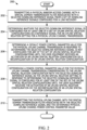
- FIG. 2 illustrates a flow diagram 200 in a user equipment for determining physical uplink channel power control parameter values for use after a beam failure recovery.
- the method includes transmitting 202 a physical random access channel with a spatial domain transmission filter associated with a selected downlink reference signal from a set of downlink reference signals configured for a link recovery.
- a determination 204 is made as to whether the selected downlink reference signal is configured for at least one of a set of uplink spatial relation configurations as a reference signal for an uplink spatial relation setting for a physical uplink channel transmission.
- a default power control parameter value for the physical uplink channel transmission is determined 206 in response to determining the selected downlink reference signal is not configured for any of the set of uplink spatial relation configurations until the user equipment receives an activation of an uplink spatial relation configuration or a reconfiguration of an uplink spatial relation configuration.
- a power control parameter value is determined 208 for the physical uplink channel transmission corresponding to the uplink spatial relation configuration with the selected downlink reference signal as the uplink spatial relation setting in response to determining the selected downlink reference signal is configured for at least one of the set of the uplink spatial relation configurations until the user equipment receives the activation of an uplink spatial relation configuration or the reconfiguration of an uplink spatial relation configuration.
- the physical uplink channel with the spatial domain transmission filter associated with the selected downlink reference signal and the determined physical uplink channel power control parameter value is then transmitted 210.
- transmitting the physical uplink channel comprises transmitting the physical uplink channel with the same spatial domain transmission filter as that used for reception of the selected downlink reference signal.
- determining the default power control parameter value for the physical uplink channel transmission in response to determining the selected downlink reference signal is not configured for any of the set of uplink spatial relation configurations includes determining a value for a user equipment specific open loop physical uplink channel power control parameter.
- as part of determining the default power control parameter value for the user equipment specific open loop physical uplink channel power control parameter includes setting the value of the user equipment specific open loop physical uplink channel power control parameter to zero and using a physical uplink channel closed loop power control adjustment state with a lowest index value.
- receiving the activation of the uplink spatial relation configuration includes receipt of the activation by higher layers, where the higher layers include a medium access control layer and the activation received in a medium access control - control element layer.
- receiving the reconfiguration of the uplink spatial relation configuration includes receiving the reconfiguration of a spatialRelationInfoToAddModList parameter configured by higher layers.
- the higher layer includes at least one of a medium access control layer and a radio resource control layer.
- the physical uplink channel is a physical uplink shared channel
- each of a set of sounding reference signal resources is associated with one of the set of uplink spatial relation configurations and maps to an SRI-PUSCHPowerControl configuration.
- the physical uplink channel is a physical uplink control channel
- the set of uplink spatial relation configurations is a set of physical uplink control channel spatial relation info configurations.
- determining the power control parameter value for the physical uplink channel transmission in response to determining the selected downlink reference signal is configured for at least one of the set of uplink spatial relation configurations includes determining a value for a user equipment specific open loop physical uplink channel power control parameter corresponding to an uplink spatial relation configuration of the at least one of the set of uplink spatial relation configurations.
- as part of determining the power control parameter value for the user equipment specific open loop physical uplink channel power control parameter includes determining a physical uplink channel closed loop power control adjustment state and a pathloss reference signal corresponding to the uplink spatial relation configuration of the at least one of the set of uplink spatial relation configurations.
- the selected downlink reference signal includes a synchronization signal/physical broadcast channel block as a reference signal for the uplink spatial relation setting, and the selected downlink reference signal used by the user equipment for physical random access channel resource selection.
- the selected downlink reference signal includes a channel state information-reference signal as a reference signal for the uplink spatial relation setting, and the selected downlink reference signal used by the user equipment for physical random access channel resource selection.
- the user equipment in response to determining the selected downlink reference signal is configured for more than one of the set of the uplink spatial relation configurations, uses the values for the power control parameters included in the uplink spatial relation configuration with the lowest uplink spatial relation index. In some of these instances, the more than one of the set of uplink spatial relation configurations are respectively associated with different service/traffic types.
- the selected downlink reference signal is a reference signal of another serving cell different than a current serving cell used for physical random access channel resource selection, and determining whether the selected downlink reference signal is configured for at least one of a set of the uplink spatial relation configurations comprises determining whether both the value of a serving cell index and the selected downlink reference signal is configured for at least one of a set of uplink spatial relation configurations.
- the user equipment determines the default power control parameter value for a user equipment specific open loop physical uplink channel power control parameter as the parameter value associated with a lowest index of a set of user equipment specific open loop physical uplink channel power control parameter values.
- FIG. 3 illustrates a flow diagram 300 in a network entity associated with the determination of a physical uplink channel power control parameter values for use in the user equipment.
- the method includes receiving 302 from a user equipment a physical random access channel transmitted with a spatial domain transmission filter associated with a selected downlink reference signal from a set of downlink reference signals configured for a link recovery.
- a physical uplink channel transmitted with the spatial domain transmission filter associated with the selected downlink reference signal and a determined physical uplink channel power control parameter value is received 304 from the user equipment.
- Whether the selected downlink reference signal is configured for at least one of a set of uplink spatial relation configurations as a reference signal for an uplink spatial relation setting for the physical uplink channel transmission is determined 306 by the user equipment.
- a default power control parameter value for the physical uplink channel transmission is determined 308 by the user equipment, in response to determining the selected downlink reference signal is not configured for any of the set of uplink spatial relation configurations, until the user equipment receives an activation of an uplink spatial relation configuration or a reconfiguration of an uplink spatial relation configuration.
- a power control parameter value for the physical uplink channel transmission corresponding to the uplink spatial relation configuration with the selected downlink reference signal as the uplink spatial relation setting is determined 310 by the user equipment, in response to determining the selected downlink reference signal is configured for at least one of the set of the uplink spatial relation configurations, until the user equipment receives the activation of an uplink spatial relation configuration or the reconfiguration of an uplink spatial relation configuration.
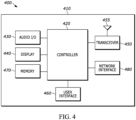
- FIG. 4 is an example block diagram of an apparatus 400, such as the wireless communication device 110, according to a possible embodiment.
- the apparatus 400 can include a housing 410, a controller 420 within the housing 410, audio input and output circuitry 430 coupled to the controller 420, a display 440 coupled to the controller 420, a transceiver 450 coupled to the controller 420, an antenna 455 coupled to the transceiver 450, a user interface 460 coupled to the controller 420, a memory 470 coupled to the controller 420, and a network interface 480 coupled to the controller 420.
- the apparatus 400 can perform the methods described in all the embodiments
- the display 440 can be a viewfinder, a liquid crystal display (LCD), a light emitting diode (LED) display, a plasma display, a projection display, a touch screen, or any other device that displays information.
- the transceiver 450 can include a transmitter and/or a receiver.
- the audio input and output circuitry 430 can include a microphone, a speaker, a transducer, or any other audio input and output circuitry.
- the user interface 460 can include a keypad, a keyboard, buttons, a touch pad, a joystick, a touch screen display, another additional display, or any other device useful for providing an interface between a user and an electronic device.
- the network interface 480 can be a Universal Serial Bus (USB) port, an Ethernet port, an infrared transmitter/receiver, an IEEE 1394 port, a WLAN transceiver, or any other interface that can connect an apparatus to a network, device, or computer and that can transmit and receive data communication signals.
- the memory 470 can include a random access memory, a read only memory, an optical memory, a solid state memory, a flash memory, a removable memory, a hard drive, a cache, or any other memory that can be coupled to an apparatus.
- the apparatus 400 or the controller 420 may implement any operating system, such as Microsoft Windows ® , UNIX ® , or LINUX ® , Android TM , or any other operating system.
- Apparatus operation software may be written in any programming language, such as C, C++, Java or Visual Basic, for example.
- Apparatus software may also run on an application framework, such as, for example, a Java ® framework, a .NET ® framework, or any other application framework.
- the software and/or the operating system may be stored in the memory 470 or elsewhere on the apparatus 400.
- the apparatus 400 or the controller 420 may also use hardware to implement disclosed operations.
- the controller 420 may be any programmable processor.
- Disclosed embodiments may also be implemented on a general-purpose or a special purpose computer, a programmed microprocessor or microprocessor, peripheral integrated circuit elements, an application-specific integrated circuit or other integrated circuits, hardware/electronic logic circuits, such as a discrete element circuit, a programmable logic device, such as a programmable logic array, field programmable gate-array, or the like.
- the controller 420 may be any controller or processor device or devices capable of operating an apparatus and implementing the disclosed embodiments. Some or all of the additional elements of the apparatus 400 can also perform some or all of the operations of the disclosed embodiments.
- the method of this disclosure can be implemented on a programmed processor.
- the controllers, flowcharts, and modules may also be implemented on a general purpose or special purpose computer, a programmed microprocessor or microcontroller and peripheral integrated circuit elements, an integrated circuit, a hardware electronic or logic circuit such as a discrete element circuit, a programmable logic device, or the like.
- any device on which resides a finite state machine capable of implementing the flowcharts shown in the figures may be used to implement the processor functions of this disclosure.
Landscapes
- Engineering & Computer Science (AREA)
- Signal Processing (AREA)
- Computer Networks & Wireless Communication (AREA)
- Mobile Radio Communication Systems (AREA)
Claims (15)
- Verfahren (200) zum Bestimmen von Leistungssteuerungsparameterwerten eines physikalischen Uplink-Kanals zur Verwendung nach einer Strahlausfallwiederherstellung in einer Benutzereinrichtung, das Verfahren umfassend:Senden (202) eines physikalischen Direktzugriffskanals mit einem Raumbereichsübertragungsfilter, der mit einem ausgewählten Downlink-Referenzsignal aus einem Satz von Downlink-Referenzsignalen verknüpft ist, die für eine Verbindungswiederherstellung konfiguriert sind;Bestimmen (204), ob das ausgewählte Downlink-Referenzsignal für mindestens eine von einem Satz von Uplink-Raumbeziehungskonfigurationen als ein Referenzsignal für eine Uplink-Raumbeziehungseinstellung für eine Übertragung des physikalischen Uplink-Kanals konfiguriert ist;Bestimmen (206) eines Standardleistungssteuerungsparameterwerts für die Übertragung des physikalischen Uplink-Kanals als Reaktion auf das Bestimmen, dass das ausgewählte Downlink-Referenzsignal für keine des Satzes von Uplink-Raumbeziehungskonfigurationen konfiguriert ist, bis die Benutzereinrichtung eine Aktivierung einer Uplink-Raumbeziehungskonfiguration oder eine Neukonfiguration einer Uplink-Raumbeziehungskonfiguration empfängt;Bestimmen (208) eines Leistungssteuerungsparameterwerts für die Übertragung des physikalischen Uplink-Kanals, die der Uplink-Raumbeziehungskonfiguration mit dem ausgewählten Downlink-Referenzsignal als der Uplink-Raumbeziehungseinstellung entspricht, als Reaktion auf das Bestimmen, dass das ausgewählte Downlink-Referenzsignal für mindestens eine von dem Satz der Uplink-Raumbeziehungskonfigurationen konfiguriert ist, bis die Benutzereinrichtung die Aktivierung einer Uplink-Raumbeziehungskonfiguration oder die Neukonfiguration einer Uplink-Raumbeziehungskonfiguration empfängt; undSenden (210) des physikalischen Uplink-Kanals mit dem Raumbereichsübertragungsfilter, der mit dem ausgewählten Downlink-Referenzsignal und dem bestimmten Leistungssteuerungsparameterwert des physikalischen Uplink-Kanals verknüpft ist.
- Verfahren (200) nach Anspruch 1, wobei ein Übertragen (210) des physischen Uplink-Kanals das Übertragen des physikalischen Uplink-Kanals mit dem gleichen Raumdomänenübertragungsfilter wie der umfasst, der für einen Empfang des ausgewählten Downlink-Referenzsignals verwendet wird.
- Verfahren (200) nach Anspruch 1, wobei das Bestimmen (206) des Standardleistungssteuerungsparameterwerts für die Übertragung des physikalischen Uplink-Kanals als Reaktion auf das Bestimmen, dass das ausgewählte Downlink-Referenzsignal für keine des Satzes von Uplink-Raumbeziehungskonfigurationen konfiguriert ist, das Bestimmen eines Werts für einen benutzereinrichtungsspezifischen Leistungssteuerungsparameter für den physischen Uplink-Kanal mit offenem Regelkreis einschließt, und optional
wobei als Teil des Bestimmens (206) des
Standardleistungssteuerungsparameterwerts für den benutzereinrichtungsspezifischen Leistungssteuerungsparameter des physikalischen Uplink-Kanals mit offenem Regelkreis ein Setzen des Werts des benutzereinrichtungsspezifischen Leistungssteuerungsparameters des physikalischen Uplink-Kanals mit offenem Regelkreis auf Null und das Verwenden eines Anpassungszustands der Leistungssteuerung des physikalischen Uplink-Kanals mit geschlossenem Regelkreis mit einem niedrigsten Indexwert einschließt. - Verfahren (200) nach Anspruch 1, wobei das Empfangen der Aktivierung der Uplink-Raumbeziehungskonfiguration den Empfang der Aktivierung durch höhere Schichten einschließt, wobei die höheren Schichten eine Medienzugriffssteuerungsschicht einschließen und die Aktivierung in einer Medienzugriffssteuerungs-Steuerelementschicht empfangen wird.
- Verfahren (200) nach Anspruch 1, wobei das Empfangen der Neukonfiguration der Uplink-Raumbeziehungskonfiguration das Empfangen der Neukonfiguration eines spatialRelationInfoToAddModList-Parameters einschließt, der durch höhere Schichten konfiguriert ist, und optional
wobei die höhere Schicht mindestens eine von einer Medienzugriffssteuerungsschicht und einer Funkressourcensteuerungsschicht einschließt. - Verfahren (200) nach Anspruch 1, wobei der physikalische Uplink-Kanal ein gemeinsam genutzter physikalischer Uplink-Kanal ist und jede eines Satzes von Sondierungsreferenzsignalressourcen mit einer von dem Satz von Uplink-Raumbeziehungskonfigurationen verknüpft ist und einer SRI-PUSCHPowerControl-Konfiguration zugeordnet ist.
- Verfahren (200) nach Anspruch 1, wobei der physikalische Uplink-Kanal ein physikalischer Uplink-Steuerkanal ist und der Satz von Uplink-Raumbeziehungskonfigurationen ein Satz von physikalischen Uplink-Steuerkanal-Raumbeziehungsinformationskonfigurationen ist.
- Verfahren (200) nach Anspruch 1, wobei das Bestimmen (208) des Leistungssteuerungsparameterwerts für die Übertragung des physikalischen Uplink-Kanals als Reaktion auf das Bestimmen, dass das ausgewählte Downlink-Referenzsignal für mindestens eine von dem Satz von Uplink-Raumbeziehungskonfigurationen konfiguriert ist, das Bestimmen eines Werts für einen benutzereinrichtungsspezifischen Leistungssteuerungsparameter des physikalischen Uplink-Kanals mit offenem Regelkreis einschließt, der einer Uplink-Raumbeziehungskonfiguration der mindestens einen von dem Satz von Uplink-Raumbeziehungskonfigurationen entspricht.
- Verfahren (200) nach Anspruch 8, wobei als Teil des Bestimmens (208) des Leistungssteuerungsparameterwerts für den benutzereinrichtungsspezifischen Leistungssteuerungsparameter des physikalischen Uplink-Kanals mit offenem Regelkreis das Bestimmen eines Anpassungszustands der Leistungssteuerung des physikalischen Uplink-Kanals mit offenem Regelkreis und eines Pfadverlustreferenzsignals entsprechend der Uplink-Raumbeziehungskonfiguration der mindestens einen von dem Satz von Uplink-Raumbeziehungskonfigurationen einschließt, und optionalwobei, nach dem Übertragen (202) des physikalischen Direktzugriffskanals und nach dem Empfangen einer Antwortnachricht, die Benutzereinrichtung alle konfigurierten Anpassungszustände der Leistungssteuerung des physikalischen Uplink-Kanals mit geschlossenem Regelkreis mit Ausnahme des bestimmten Anpassungszustands der Leistungssteuerung des physikalischen Uplink-Kanals mit geschlossenem Regelkreis zurücksetzt.
- Verfahren (200) nach Anspruch 1, wobei das ausgewählte Downlink-Referenzsignal ein Synchronisierungssignal/einen Block eines physikalischen Broadcast-Kanals als ein Referenzsignal für die Uplink-Raumbeziehungseinstellung einschließt und das ausgewählte Downlink-Referenzsignal durch die Benutzereinrichtung für eine Ressourcenauswahl des physikalischen Direktzugriffskanals verwendet wird.
- Verfahren (200) nach Anspruch 1, wobei das ausgewählte Downlink-Referenzsignal ein Kanalzustandsinformationsreferenzsignal als ein Referenzsignal für die Uplink-Raumbeziehungseinstellung einschließt und das ausgewählte Downlink-Referenzsignal durch die Benutzereinrichtung für die Ressourcenauswahl des physikalischen Direktzugriffskanals verwendet wird.
- Verfahren (200) nach Anspruch 1, wobei als Reaktion auf das Bestimmen (204), dass das ausgewählte Downlink-Referenzsignal für mehr als eine von dem Satz der Uplink-Raumbeziehungskonfigurationen konfiguriert ist, die Benutzereinrichtung die Werte für die Leistungssteuerungsparameter verwendet, die in der Uplink-Raumbeziehungskonfiguration mit dem niedrigsten Uplink-Raumbeziehungsindex eingeschlossen sind, und optional
wobei die mehr als eine von dem Satz von Uplink-
Raumbeziehungsgruppenkonfigurationen jeweils mit unterschiedlichen Dienst-/Verkehrsarten verknüpft sind. - Verfahren (200) nach Anspruch 1, wobei das ausgewählte Downlink-Referenzsignal ein Referenzsignal einer anderen aktiven Funkzelle ist, die sich von einer aktuellen aktiven Funkzelle unterscheidet, die für die Ressourcenauswahl des physikalischen Direktzugriffskanals verwendet wird, und wobei das Bestimmen (204), ob das ausgewählte Downlink-Referenzsignal für mindestens eine von einem Satz von Uplink-Raumbeziehungskonfigurationen konfiguriert ist, das Bestimmen umfasst, ob sowohl der Wert eines Index der aktiven Funkzelle als auch das ausgewählte Downlink-Referenzsignal für mindestens eine von einem Satz von Uplink-Raumbeziehungskonfigurationen konfiguriert sind.
- Verfahren (200) nach Anspruch 1, wobei während der Verbindungswiederherstellung, während in einem verbundenen Modus, falls die Benutzereinrichtung mit keiner der mindestens einen von einem Satz von Uplink-Raumbeziehungskonfigurationen konfiguriert ist, die Benutzereinrichtung dann den Standardleistungssteuerungsparameterwert für einen benutzereinrichtungsspezifischen Leistungssteuerungsparameter für einen physikalischen Uplink-Kanal mit offenem Regelkreis als den Parameterwert bestimmt, der mit einem niedrigsten Index eines Satzes von benutzereinrichtungsspezifischen Leistungssteuerungsparameterwerten für einen physikalischen Uplink-Kanal mit offenem Regelkreis verknüpft ist.
- Benutzereinrichtung (400) in einem Kommunikationsnetzwerk, die Benutzereinrichtung umfassend:einen Transceiver (450), der eingerichtet ist, um einen physikalischen Direktzugriffskanal mit einem Raumbereichsübertragungsfilter zu übertragen, der mit einem ausgewählten Downlink-Referenzsignal aus einem Satz von Downlink-Referenzsignalen verknüpft ist, die für eine Verbindungswiederherstellung konfiguriert sind; undeine Steuervorrichtung (420), die eingerichtet ist, um zu bestimmen, ob das ausgewählte Downlink-Referenzsignal für mindestens eine von einem Satz von Uplink-Raumbeziehungskonfigurationen als ein Referenzsignal für eine Uplink-Raumbeziehungseinstellung für eine Übertragung des physikalischen Uplink-Kanals konfiguriert ist;wobei die Steuervorrichtung (420) ferner eingerichtet ist, um einen Standardleistungssteuerungsparameterwert für die Übertragung des physikalischen Uplink-Kanals als Reaktion auf das Bestimmen zu bestimmen, dass das ausgewählte Downlink-Referenzsignal für keine des Satzes von Uplink-Raumbeziehungskonfigurationen konfiguriert ist, bis die Benutzereinrichtung eine Aktivierung einer Uplink-Raumbeziehungskonfiguration oder eine Neukonfiguration einer Uplink-Raumbeziehungskonfiguration empfängt;wobei die Steuervorrichtung (420) ferner eingerichtet ist, um einen Leistungssteuerungsparameterwert für die Übertragung des physikalischen Uplink-Kanals entsprechend der Uplink-Raumbeziehungskonfiguration mit dem ausgewählten Downlink-Referenzsignal als das Uplink-Raumbeziehungseinstellung als Reaktion auf das Bestimmen zu bestimmen, dass das ausgewählte Downlink-Referenzsignal für mindestens eine von dem Satz der Uplink-Raumbeziehungskonfigurationen konfiguriert ist, bis die Benutzereinrichtung die Aktivierung einer Uplink-Raumbeziehungskonfiguration oder die Neukonfiguration einer Uplink-Raumbeziehungskonfiguration empfängt; undwobei der Transceiver (450) ferner eingerichtet ist, um den physikalischen Uplink-Kanal mit dem Raumbereichsübertragungsfilter zu übertragen, der mit dem ausgewählten Downlink-Referenzsignal und dem bestimmten Leistungssteuerungsparameterwert des physikalischen Uplink-Kanals verknüpft ist.
Applications Claiming Priority (2)
| Application Number | Priority Date | Filing Date | Title |
|---|---|---|---|
| US201862744602P | 2018-10-11 | 2018-10-11 | |
| PCT/IB2019/058704 WO2020075138A1 (en) | 2018-10-11 | 2019-10-11 | Method and apparatus for determining physical uplink channel power control parameter values for use after a beam failure recovery |
Publications (3)
| Publication Number | Publication Date |
|---|---|
| EP3864904A1 EP3864904A1 (de) | 2021-08-18 |
| EP3864904B1 true EP3864904B1 (de) | 2025-03-12 |
| EP3864904C0 EP3864904C0 (de) | 2025-03-12 |
Family
ID=68296572
Family Applications (1)
| Application Number | Title | Priority Date | Filing Date |
|---|---|---|---|
| EP19790824.7A Active EP3864904B1 (de) | 2018-10-11 | 2019-10-11 | Verfahren und vorrichtung zur bestimmung physikalischer uplink-kanalleistungssteuerparameterwerte zur verwendung nach einer strahlausfallwiederherstellung |
Country Status (4)
| Country | Link |
|---|---|
| US (2) | US10992366B2 (de) |
| EP (1) | EP3864904B1 (de) |
| CN (1) | CN112673681B (de) |
| WO (1) | WO2020075138A1 (de) |
Families Citing this family (35)
| Publication number | Priority date | Publication date | Assignee | Title |
|---|---|---|---|---|
| US11153137B2 (en) * | 2017-09-29 | 2021-10-19 | Lenovo (Beijing) Limited | Feedback message having a sequence indicating feedback information corresponding to data blocks |
| EP4366400A3 (de) * | 2017-11-23 | 2024-07-24 | Toyota Jidosha Kabushiki Kaisha | Signalübertragungsverfahren, endgerätevorrichtung und netzwerkvorrichtung |
| WO2020061844A1 (zh) | 2018-09-26 | 2020-04-02 | 富士通株式会社 | 信号发送方法、信号接收方法及装置 |
| US11785511B2 (en) * | 2018-10-09 | 2023-10-10 | Telefonaktiebolaget Lm Ericsson (Publ) | Inter-RAT (radio access technology) re-establishment enhancements in multi-RAT dual connectivity (MR-DC) |
| CN113273094B (zh) * | 2018-10-31 | 2024-05-14 | 株式会社Ntt都科摩 | 终端、基站、系统以及无线通信方法 |
| CN114389664B (zh) * | 2018-11-02 | 2024-01-19 | 中兴通讯股份有限公司 | 无线通信方法、无线通信装置、存储介质 |
| US11445446B2 (en) * | 2018-11-09 | 2022-09-13 | Lenovo (Beijing) Limited | Methods and apparatuses for power control |
| US12501377B2 (en) * | 2019-01-04 | 2025-12-16 | Huawei Technologies Co., Ltd. | Sounding reference signal for uplink-based multi-cell measurement |
| US11632756B2 (en) * | 2019-02-13 | 2023-04-18 | Ofinno, Llc | Beam management and beam indication in a radio system |
| KR102671061B1 (ko) * | 2019-02-15 | 2024-05-31 | 에프쥐 이노베이션 컴퍼니 리미티드 | 빔 장애 복구를 위한 방법들 및 장치들 |
| CN115038177B (zh) * | 2019-03-29 | 2025-10-24 | 中兴通讯股份有限公司 | 传输指示方法和装置 |
| US11303345B2 (en) | 2019-05-02 | 2022-04-12 | Ofinno, Llc | Beam failure recovery procedure in carrier aggregation |
| US20220210745A1 (en) * | 2019-05-15 | 2022-06-30 | Ntt Docomo, Inc. | User terminal and radio communication method |
| US11251919B2 (en) * | 2019-05-17 | 2022-02-15 | Qualcomm Incorporated | Panel selection for user equipment with multiple panels |
| EP3962183B1 (de) * | 2019-11-06 | 2024-10-09 | Guangdong Oppo Mobile Telecommunications Corp., Ltd. | Verfahren zur aktivierung oder aktualisierung von pusch-pfadverlust-rs und vorrichtung |
| US11729723B2 (en) * | 2019-11-21 | 2023-08-15 | Qualcomm Incorporated | Power control indication for multiple services |
| WO2021120173A1 (en) * | 2019-12-20 | 2021-06-24 | Qualcomm Incorporated | Medium access control layer mapping for pathloss reference signal |
| WO2021142432A1 (en) * | 2020-01-09 | 2021-07-15 | Ofinno, Llc | Power headroom report based on dynamic pathloss estimation |
| US11589394B2 (en) * | 2020-02-13 | 2023-02-21 | Qualcomm Incorporated | Managing beam failure recovery random access |
| US12610367B2 (en) * | 2020-02-24 | 2026-04-21 | Nokia Technologies Oy | Transmission of UCI via re-configurable PUCCH |
| US11785594B2 (en) * | 2020-03-16 | 2023-10-10 | Qualcomm Incorporated | Multi-downlink control information message related to physical uplink shared channels |
| WO2021210182A1 (ja) * | 2020-04-17 | 2021-10-21 | 株式会社Nttドコモ | 端末、無線通信方法及び基地局 |
| JP7602534B2 (ja) * | 2020-04-28 | 2024-12-18 | 株式会社Nttドコモ | 端末、無線通信方法及びシステム |
| WO2021229819A1 (ja) * | 2020-05-15 | 2021-11-18 | 株式会社Nttドコモ | 端末、無線通信方法及び基地局 |
| CN115668799B (zh) * | 2020-05-28 | 2025-09-09 | 高通股份有限公司 | 管理波束故障恢复更新 |
| WO2022030849A1 (ko) * | 2020-08-07 | 2022-02-10 | 엘지전자 주식회사 | 무선 통신 시스템에서 상향링크 송수신 방법 및 장치 |
| EP4154644B1 (de) * | 2020-09-15 | 2024-11-27 | Guangdong Oppo Mobile Telecommunications Corp., Ltd. | Verfahren und vorrichtung zur strahlausfallwiederherstellung |
| WO2022056702A1 (en) * | 2020-09-16 | 2022-03-24 | Apple Inc. | Using aperiodic reference signals for a spatial relationship update |
| EP4252366A4 (de) * | 2020-11-30 | 2024-08-14 | Lenovo (Beijing) Limited | Verfahren und vorrichtungen zur übertragung eines gemeinsam genutzten physikalischen uplink-kanals |
| CN117615441A (zh) * | 2020-12-29 | 2024-02-27 | Oppo广东移动通信有限公司 | 上行功率控制方法及终端设备 |
| US11540236B2 (en) * | 2021-03-08 | 2022-12-27 | Qualcomm Incorporated | Cell-group transmission power control commands |
| US20220353131A1 (en) * | 2021-04-29 | 2022-11-03 | Qualcomm Incorporated | Uplink beam continuation for downlink beam failure recovery |
| US11665737B2 (en) * | 2021-04-30 | 2023-05-30 | Qualcomm Incorporated | Spatial relation information based on random access messages |
| WO2023130297A1 (en) * | 2022-01-06 | 2023-07-13 | Lenovo (Beijing) Limited | Power control parameters corresponding to beam failure recovery |
| US20250183984A1 (en) * | 2022-04-22 | 2025-06-05 | Qualcomm Incorporated | Power control parameter reset associated with beam failure recovery |
Family Cites Families (6)
| Publication number | Priority date | Publication date | Assignee | Title |
|---|---|---|---|---|
| US8514826B2 (en) * | 2010-11-02 | 2013-08-20 | Lg Electronics Inc. | Method and apparatus for transmitting control information in radio communication system |
| MX2014000918A (es) * | 2011-08-09 | 2014-05-12 | Ericsson Telefon Ab L M | Metodo y disposicion para el control de potencia de enlace ascendente. |
| WO2017061909A1 (en) * | 2015-10-05 | 2017-04-13 | Telefonaktiebolaget Lm Ericsson (Publ) | Method and apparatus to account for effective downlink channels arising from beamforming uplink reference signals |
| CN108633043B (zh) * | 2017-03-24 | 2021-06-29 | 中兴通讯股份有限公司 | 波束恢复的处理方法及装置 |
| US10750453B2 (en) * | 2017-09-07 | 2020-08-18 | Ofinno, Llc | Sounding reference signal transmission for uplink beam management |
| US10660077B2 (en) * | 2018-08-09 | 2020-05-19 | Lenovo (Singapore) Pte Ltd | Uplink transmission power allocation |
-
2019
- 2019-10-11 EP EP19790824.7A patent/EP3864904B1/de active Active
- 2019-10-11 WO PCT/IB2019/058704 patent/WO2020075138A1/en not_active Ceased
- 2019-10-11 CN CN201980060037.4A patent/CN112673681B/zh active Active
- 2019-10-11 US US16/599,269 patent/US10992366B2/en active Active
-
2021
- 2021-03-22 US US17/208,171 patent/US11463147B2/en active Active
Non-Patent Citations (1)
| Title |
|---|
| ZTE: "Maintenance for UL power control", vol. RAN WG1, no. Chengdu, China; 20181008 - 20181012, 29 September 2018 (2018-09-29), XP051517633, Retrieved from the Internet <URL:http://www.3gpp.org/ftp/tsg%5Fran/WG1%5FRL1/TSGR1%5F94b/Docs/R1%2D1810217%2Ezip> [retrieved on 20180929] * |
Also Published As
| Publication number | Publication date |
|---|---|
| CN112673681A (zh) | 2021-04-16 |
| US11463147B2 (en) | 2022-10-04 |
| US20210211180A1 (en) | 2021-07-08 |
| US20200119799A1 (en) | 2020-04-16 |
| CN112673681B (zh) | 2024-07-30 |
| EP3864904C0 (de) | 2025-03-12 |
| EP3864904A1 (de) | 2021-08-18 |
| US10992366B2 (en) | 2021-04-27 |
| WO2020075138A1 (en) | 2020-04-16 |
Similar Documents
| Publication | Publication Date | Title |
|---|---|---|
| US11463147B2 (en) | Method and apparatus for determining physical uplink channel power control parameter values for use after a beam failure recovery | |
| US11979268B2 (en) | Method and apparatus for selecting an antenna port using received antenna port specific adjustments | |
| US12160831B2 (en) | Reference signal determination method and device, and UE | |
| US12349144B2 (en) | Method and device for transmitting MSG3 | |
| JP7468678B2 (ja) | ネットワーク装置、端末装置、及び方法 | |
| US12407485B2 (en) | Implicit update of activated TCI states | |
| KR20220062451A (ko) | 빔 관리 방법 및 장치, 사용자 기기 | |
| JP4705040B2 (ja) | 不連続送信の状態値に基づいてダウンリンクおよびアップリンクの符号化複合トランスポートチャネルにおける送信電力を制御するための無線通信方法および装置 | |
| CN115299121B (zh) | 对pucch重复进行功率控制的方法及设备 | |
| TWI829364B (zh) | 無線通信方法及用戶設備 | |
| EP4266769A1 (de) | Direktzugriffsverfahren sowie elektronische vorrichtung und speichermedium | |
| CN117981406A (zh) | 用于处理上行链路传输定时差的方法及设备 | |
| WO2022141438A1 (en) | Method and apparatus for performing random access | |
| EP3588820B1 (de) | Datenübertragungsverfahren und -vorrichtung | |
| US10091735B2 (en) | Systems and methods for power control in wireless networks | |
| EP3113552A1 (de) | Verfahren zur steuerung der uplink-leistung, benutzervorrichtung und basisstationen | |
| CN113543042A (zh) | 功率上报方法和设备 | |
| US20250227621A1 (en) | Power control method and apparatus, device, and storage medium | |
| US20240349199A1 (en) | Channel estimation accuracy improvement for srs antenna switching | |
| WO2022261930A1 (en) | Method and apparatus for beam determination | |
| US20240314774A1 (en) | Method and apparatus for uplink transmission | |
| WO2021147087A1 (en) | Method and apparatus for deactivating user equipment panels | |
| JPWO2023162724A5 (ja) | 端末、無線通信方法、基地局及びシステム |
Legal Events
| Date | Code | Title | Description |
|---|---|---|---|
| STAA | Information on the status of an ep patent application or granted ep patent |
Free format text: STATUS: UNKNOWN |
|
| STAA | Information on the status of an ep patent application or granted ep patent |
Free format text: STATUS: THE INTERNATIONAL PUBLICATION HAS BEEN MADE |
|
| PUAI | Public reference made under article 153(3) epc to a published international application that has entered the european phase |
Free format text: ORIGINAL CODE: 0009012 |
|
| STAA | Information on the status of an ep patent application or granted ep patent |
Free format text: STATUS: REQUEST FOR EXAMINATION WAS MADE |
|
| 17P | Request for examination filed |
Effective date: 20210308 |
|
| AK | Designated contracting states |
Kind code of ref document: A1 Designated state(s): AL AT BE BG CH CY CZ DE DK EE ES FI FR GB GR HR HU IE IS IT LI LT LU LV MC MK MT NL NO PL PT RO RS SE SI SK SM TR |
|
| DAV | Request for validation of the european patent (deleted) | ||
| DAX | Request for extension of the european patent (deleted) | ||
| STAA | Information on the status of an ep patent application or granted ep patent |
Free format text: STATUS: EXAMINATION IS IN PROGRESS |
|
| 17Q | First examination report despatched |
Effective date: 20221013 |
|
| REG | Reference to a national code |
Ref country code: DE Ref legal event code: R079 Free format text: PREVIOUS MAIN CLASS: H04W0052140000 Ipc: H04W0074083300 Ref country code: DE Ref legal event code: R079 Ref document number: 602019067215 Country of ref document: DE Free format text: PREVIOUS MAIN CLASS: H04W0052140000 Ipc: H04W0074083300 |
|
| GRAP | Despatch of communication of intention to grant a patent |
Free format text: ORIGINAL CODE: EPIDOSNIGR1 |
|
| STAA | Information on the status of an ep patent application or granted ep patent |
Free format text: STATUS: GRANT OF PATENT IS INTENDED |
|
| RIC1 | Information provided on ipc code assigned before grant |
Ipc: H04B 7/08 20060101ALI20240917BHEP Ipc: H04B 7/06 20060101ALI20240917BHEP Ipc: H04W 52/22 20090101ALI20240917BHEP Ipc: H04W 52/50 20090101ALI20240917BHEP Ipc: H04W 52/48 20090101ALI20240917BHEP Ipc: H04W 52/32 20090101ALI20240917BHEP Ipc: H04W 52/08 20090101ALI20240917BHEP Ipc: H04W 52/14 20090101ALI20240917BHEP Ipc: H04W 52/10 20090101ALI20240917BHEP Ipc: H04W 74/0833 20240101AFI20240917BHEP |
|
| INTG | Intention to grant announced |
Effective date: 20241008 |
|
| GRAS | Grant fee paid |
Free format text: ORIGINAL CODE: EPIDOSNIGR3 |
|
| GRAA | (expected) grant |
Free format text: ORIGINAL CODE: 0009210 |
|
| STAA | Information on the status of an ep patent application or granted ep patent |
Free format text: STATUS: THE PATENT HAS BEEN GRANTED |
|
| AK | Designated contracting states |
Kind code of ref document: B1 Designated state(s): AL AT BE BG CH CY CZ DE DK EE ES FI FR GB GR HR HU IE IS IT LI LT LU LV MC MK MT NL NO PL PT RO RS SE SI SK SM TR |
|
| REG | Reference to a national code |
Ref country code: GB Ref legal event code: FG4D |
|
| REG | Reference to a national code |
Ref country code: CH Ref legal event code: EP |
|
| REG | Reference to a national code |
Ref country code: DE Ref legal event code: R096 Ref document number: 602019067215 Country of ref document: DE |
|
| REG | Reference to a national code |
Ref country code: IE Ref legal event code: FG4D |
|
| U01 | Request for unitary effect filed |
Effective date: 20250401 |
|
| U07 | Unitary effect registered |
Designated state(s): AT BE BG DE DK EE FI FR IT LT LU LV MT NL PT RO SE SI Effective date: 20250407 |
|
| PG25 | Lapsed in a contracting state [announced via postgrant information from national office to epo] |
Ref country code: RS Free format text: LAPSE BECAUSE OF FAILURE TO SUBMIT A TRANSLATION OF THE DESCRIPTION OR TO PAY THE FEE WITHIN THE PRESCRIBED TIME-LIMIT Effective date: 20250612 |
|
| PG25 | Lapsed in a contracting state [announced via postgrant information from national office to epo] |
Ref country code: ES Free format text: LAPSE BECAUSE OF FAILURE TO SUBMIT A TRANSLATION OF THE DESCRIPTION OR TO PAY THE FEE WITHIN THE PRESCRIBED TIME-LIMIT Effective date: 20250312 |
|
| PG25 | Lapsed in a contracting state [announced via postgrant information from national office to epo] |
Ref country code: NO Free format text: LAPSE BECAUSE OF FAILURE TO SUBMIT A TRANSLATION OF THE DESCRIPTION OR TO PAY THE FEE WITHIN THE PRESCRIBED TIME-LIMIT Effective date: 20250612 |
|
| PG25 | Lapsed in a contracting state [announced via postgrant information from national office to epo] |
Ref country code: HR Free format text: LAPSE BECAUSE OF FAILURE TO SUBMIT A TRANSLATION OF THE DESCRIPTION OR TO PAY THE FEE WITHIN THE PRESCRIBED TIME-LIMIT Effective date: 20250312 |
|
| PG25 | Lapsed in a contracting state [announced via postgrant information from national office to epo] |
Ref country code: GR Free format text: LAPSE BECAUSE OF FAILURE TO SUBMIT A TRANSLATION OF THE DESCRIPTION OR TO PAY THE FEE WITHIN THE PRESCRIBED TIME-LIMIT Effective date: 20250613 |
|
| PG25 | Lapsed in a contracting state [announced via postgrant information from national office to epo] |
Ref country code: SM Free format text: LAPSE BECAUSE OF FAILURE TO SUBMIT A TRANSLATION OF THE DESCRIPTION OR TO PAY THE FEE WITHIN THE PRESCRIBED TIME-LIMIT Effective date: 20250312 |
|
| PG25 | Lapsed in a contracting state [announced via postgrant information from national office to epo] |
Ref country code: PL Free format text: LAPSE BECAUSE OF FAILURE TO SUBMIT A TRANSLATION OF THE DESCRIPTION OR TO PAY THE FEE WITHIN THE PRESCRIBED TIME-LIMIT Effective date: 20250312 |
|
| PG25 | Lapsed in a contracting state [announced via postgrant information from national office to epo] |
Ref country code: CZ Free format text: LAPSE BECAUSE OF FAILURE TO SUBMIT A TRANSLATION OF THE DESCRIPTION OR TO PAY THE FEE WITHIN THE PRESCRIBED TIME-LIMIT Effective date: 20250312 |
|
| PG25 | Lapsed in a contracting state [announced via postgrant information from national office to epo] |
Ref country code: SK Free format text: LAPSE BECAUSE OF FAILURE TO SUBMIT A TRANSLATION OF THE DESCRIPTION OR TO PAY THE FEE WITHIN THE PRESCRIBED TIME-LIMIT Effective date: 20250312 |
|
| PG25 | Lapsed in a contracting state [announced via postgrant information from national office to epo] |
Ref country code: IS Free format text: LAPSE BECAUSE OF FAILURE TO SUBMIT A TRANSLATION OF THE DESCRIPTION OR TO PAY THE FEE WITHIN THE PRESCRIBED TIME-LIMIT Effective date: 20250712 |
|
| U20 | Renewal fee for the european patent with unitary effect paid |
Year of fee payment: 7 Effective date: 20251027 |
|
| PGFP | Annual fee paid to national office [announced via postgrant information from national office to epo] |
Ref country code: GB Payment date: 20251023 Year of fee payment: 7 |
|
| PLBE | No opposition filed within time limit |
Free format text: ORIGINAL CODE: 0009261 |
|
| STAA | Information on the status of an ep patent application or granted ep patent |
Free format text: STATUS: NO OPPOSITION FILED WITHIN TIME LIMIT |
|
| REG | Reference to a national code |
Ref country code: CH Ref legal event code: L10 Free format text: ST27 STATUS EVENT CODE: U-0-0-L10-L00 (AS PROVIDED BY THE NATIONAL OFFICE) Effective date: 20260121 |
|
| 26N | No opposition filed |
Effective date: 20251215 |