EP3864930B1 - Noeud de réseau et procédé dans un réseau de communications sans fil - Google Patents
Noeud de réseau et procédé dans un réseau de communications sans fil Download PDFInfo
- Publication number
- EP3864930B1 EP3864930B1 EP19871680.5A EP19871680A EP3864930B1 EP 3864930 B1 EP3864930 B1 EP 3864930B1 EP 19871680 A EP19871680 A EP 19871680A EP 3864930 B1 EP3864930 B1 EP 3864930B1
- Authority
- EP
- European Patent Office
- Prior art keywords
- pdcp
- pdus
- network node
- pdcp pdus
- pdu
- Prior art date
- Legal status (The legal status is an assumption and is not a legal conclusion. Google has not performed a legal analysis and makes no representation as to the accuracy of the status listed.)
- Not-in-force
Links
Images




Classifications
-
- H—ELECTRICITY
- H04—ELECTRIC COMMUNICATION TECHNIQUE
- H04L—TRANSMISSION OF DIGITAL INFORMATION, e.g. TELEGRAPHIC COMMUNICATION
- H04L1/00—Arrangements for detecting or preventing errors in the information received
- H04L1/12—Arrangements for detecting or preventing errors in the information received by using return channel
- H04L1/16—Arrangements for detecting or preventing errors in the information received by using return channel in which the return channel carries supervisory signals, e.g. repetition request signals
- H04L1/18—Automatic repetition systems, e.g. Van Duuren systems
- H04L1/1829—Arrangements specially adapted for the receiver end
- H04L1/1835—Buffer management
- H04L1/1841—Resequencing
-
- H—ELECTRICITY
- H04—ELECTRIC COMMUNICATION TECHNIQUE
- H04L—TRANSMISSION OF DIGITAL INFORMATION, e.g. TELEGRAPHIC COMMUNICATION
- H04L1/00—Arrangements for detecting or preventing errors in the information received
- H04L1/12—Arrangements for detecting or preventing errors in the information received by using return channel
- H04L1/16—Arrangements for detecting or preventing errors in the information received by using return channel in which the return channel carries supervisory signals, e.g. repetition request signals
- H04L1/18—Automatic repetition systems, e.g. Van Duuren systems
- H04L1/1867—Arrangements specially adapted for the transmitter end
- H04L1/1874—Buffer management
-
- H—ELECTRICITY
- H04—ELECTRIC COMMUNICATION TECHNIQUE
- H04L—TRANSMISSION OF DIGITAL INFORMATION, e.g. TELEGRAPHIC COMMUNICATION
- H04L1/00—Arrangements for detecting or preventing errors in the information received
- H04L1/12—Arrangements for detecting or preventing errors in the information received by using return channel
- H04L1/16—Arrangements for detecting or preventing errors in the information received by using return channel in which the return channel carries supervisory signals, e.g. repetition request signals
- H04L1/18—Automatic repetition systems, e.g. Van Duuren systems
- H04L1/1867—Arrangements specially adapted for the transmitter end
- H04L1/1887—Scheduling and prioritising arrangements
-
- H—ELECTRICITY
- H04—ELECTRIC COMMUNICATION TECHNIQUE
- H04L—TRANSMISSION OF DIGITAL INFORMATION, e.g. TELEGRAPHIC COMMUNICATION
- H04L47/00—Traffic control in data switching networks
- H04L47/10—Flow control; Congestion control
- H04L47/34—Flow control; Congestion control ensuring sequence integrity, e.g. using sequence numbers
-
- H—ELECTRICITY
- H04—ELECTRIC COMMUNICATION TECHNIQUE
- H04L—TRANSMISSION OF DIGITAL INFORMATION, e.g. TELEGRAPHIC COMMUNICATION
- H04L69/00—Network arrangements, protocols or services independent of the application payload and not provided for in the other groups of this subclass
- H04L69/03—Protocol definition or specification
-
- H—ELECTRICITY
- H04—ELECTRIC COMMUNICATION TECHNIQUE
- H04W—WIRELESS COMMUNICATION NETWORKS
- H04W80/00—Wireless network protocols or protocol adaptations to wireless operation
- H04W80/02—Data link layer protocols
-
- H—ELECTRICITY
- H04—ELECTRIC COMMUNICATION TECHNIQUE
- H04W—WIRELESS COMMUNICATION NETWORKS
- H04W28/00—Network traffic management; Network resource management
- H04W28/02—Traffic management, e.g. flow control or congestion control
- H04W28/0205—Traffic management, e.g. flow control or congestion control at the air interface
-
- H—ELECTRICITY
- H04—ELECTRIC COMMUNICATION TECHNIQUE
- H04W—WIRELESS COMMUNICATION NETWORKS
- H04W88/00—Devices specially adapted for wireless communication networks, e.g. terminals, base stations or access point devices
- H04W88/08—Access point devices
- H04W88/085—Access point devices with remote components
Definitions
- Embodiments herein relate to a network node, and a method therein. In particular, they relate to transmitting a Packet Data Convergence Protocol (PDCP) Protocol Data Unit (PDU) to a wireless communications device.
- PDCP Packet Data Convergence Protocol
- PDU Protocol Data Unit
- wireless devices also known as wireless communication devices, mobile stations, stations (STA) and/or User Equipments (UE), communicate via a Local Area Network such as a Wi-Fi network or a Radio Access Network (RAN) to one or more core networks (CN).
- the RAN covers a geographical area which is divided into service areas or cell areas, which may also be referred to as a beam or a beam group, with each service area or cell area being served by a radio network node such as a radio access node e.g., a Wi-Fi access point or a radio base station (RBS), which in some networks may also be denoted, for example, a NodeB, eNodeB (eNB), or gNB as denoted in 5G.
- a service area or cell area is a geographical area where radio coverage is provided by the radio network node.
- the radio network node communicates over an air interface operating on radio frequencies with the wireless device within range of the radio network node.
- the Evolved Packet System also called a Fourth Generation (4G) network
- EPS also called a Fourth Generation (4G) network
- 3GPP 3rd Generation Partnership Project
- 5G Fifth Generation
- NR 5G New Radio
- NG Next Generation
- the EPS comprises the Evolved Universal Terrestrial Radio Access Network (E-UTRAN), also known as the Long Term Evolution (LTE) radio access network, and the Evolved Packet Core (EPC), also known as System Architecture Evolution (SAE) core network.
- E-UTRAN also known as the Long Term Evolution (LTE) radio access network
- EPC Evolved Packet Core
- SAE System Architecture Evolution
- E-UTRAN/LTE is a variant of a 3GPP radio access network wherein the radio network nodes are directly connected to the EPC core network rather than to RNCs used in 3G networks.
- the functions of a 3G RNC are distributed between the radio network nodes, e.g. eNodeBs in LTE, and the core network.
- the RAN of an EPS has an essentially "flat" architecture comprising radio network nodes connected directly to one or more core networks, i.e. they are not connected to RNCs.
- the E-UTRAN specification defines a direct interface between the radio network nodes, this interface being denoted the X2 interface.
- Multi-antenna techniques may significantly increase the data rates and reliability of a wireless communication system. The performance is in particular improved if both the transmitter and the receiver are equipped with multiple antennas, which results in a Multiple-Input Multiple-Output (MIMO) communication channel.
- MIMO Multiple-Input Multiple-Output
- Such systems and/or related techniques are commonly referred to as MIMO.
- DC NG-RAN dual connectivity
- One DC configuration is when an eNB and a gNB are connected with the same UE (called Enhanced DC (EN-DC), and another configuration is when two gNBs are connected with the same UE.
- EN-DC Enhanced DC
- a DC connection may be setup and released dynamically based on various characteristics, such as whether a good enough radio connection can be setup or not with the UE from a specific node (gNB or eNB).
- FIG. 1 shows an overview of the architecture in NG-RAN where gNBs may be interconnected through an Xn interface.
- a gNB may comprise a gNB- Central Unit (CU) and gNB- Distributed Unit (DU)s.
- CU Central Unit
- DU Distributed Unit
- a gNB-CU and a gNB-DU may be connected via F1 logical interface.
- One gNB-DU is connected to only one gNB-CU.
- Data transmission for dual connectivity is controlled by a controlling node called a Central Unit (CU), and the network nodes (eNB or gNB) for which the CU controls the data traffic are referred to as distributed units, called DUs.
- the CU may be collocated within the same node, e.g. a network node such as eNB or gNB, as one of the DUs or it may be located in its own node, see Figure 2 depicting two examples of DC deployments.
- xNB is either a gNB or an eNB.
- the UE When a UE has a Data Radio Bearer (DRB) connection with only one DU, and hence is not using dual connectivity, the UE has a single DC leg, and when a UE has a DRB connection with two DUs the UE has two DC legs and is in dual connectivity.
- the network may actively use either one or both of the legs for the ongoing traffic.
- non-aggregated data transmission and when both legs are used for traffic it is in this document referred to as “aggregated” data transmission.
- a UE that has an ongoing data traffic for a DRB connection and which is capable of dual connectivity may occasionally be reconfigured by the network from having a single leg connection to dual connectivity and vice versa, and furthermore, when the DRB is configured for dual connectivity, the network may dynamically change between using aggregated and non-aggregated data transmission for the DRB.
- 3GPP has agreed that CU-UP may retransmit Packet Data Convergence Protocol (PDCP) Protocol Data Unit (PDU)s. Such retransmitted PDUs shall be marked with a Retransmission flag in the frame when transmitted from the CU-UP to the DU. See 3GPP TS 38.425 ref. It is also agreed to allow sending feedback DL Data Delivery Status messages (DDDS) from DU to CU-UP including.
- PDCP Packet Data Convergence Protocol
- PDU Protocol Data Unit
- the DDDS may include information elements as "Highest successfully delivered NR PDCP Sequence Number”, “Highest transmitted NR PDCP Sequence Number”, “Highest successfully delivered retransmitted NR PDCP Sequence Number” and “Highest retransmitted NR PDCP Sequence Number” information elements (IE), see 3GPP TS 38.425. This means that all PDUs marked as retransmitted when transmitted from CU-User Plane (U) to DU also shall be separated as retransmitted when reported in the DDDS and acknowledged to the CU-UP.
- IE Highest retransmitted NR PDCP Sequence Number
- An object of embodiments herein is to improve the performance of the network such as a wireless communications network.
- the invention is defined by a method (as in claim 1), a computer program (as in claim 10), a carrier (as in claim 11) and a network node (as in claim 12).
- the object is achieved by a method performed by a network node for transmission of a Packet Data Convergence Protocol, PDCP, Protocol Data Unit, PDU, to a wireless communications device.
- the network node and the wireless communications device operate in a wireless communications network.
- the network node arranges a number of PDCP PDUs in a numerical order based on their respective PDCP Sequence Number, SN.
- the number of PDCP PDUs is taken from a first set of PDCP PDUs comprising one or more first time transmitted PDCP PDUs and from a second set of PDCP PDUs comprising one or more retransmitted PDCP PDUs.
- the one or more first time transmitted PDCP PDUs and the one or more retransmitted PDCP PDUs are received from a controlling node.
- the network node transmits the number of the PDCP PDUs in the numerical order to the wireless communications device.
- the object is achieved by a network node, for transmission of a Packet Data Convergence Protocol, PDCP, Protocol Data Unit, PDU, to a wireless communications device.
- the network node and the wireless communications device are configured to operate in a wireless communications network.
- the network node is further configured to:
- Embodiments herein provide an improved retransmission handling.
- the PDUs can be transmitted to the UE in correct PDCP SN order with improved end user performance as a result.
- PDUs received out of ordered will be queued up waiting for missing PDCP SN why the end user will experience shorter latency if no reordering occur.
- a large reordering will additionally (when reordering timer expiries in UE) cause packet discard, and this is reducing end user performance even further.
- An object of embodiments herein may therefore be to improve end user performance in a wireless communications network.
- Embodiments herein relate to improved retransmission handling.
- reordering of first time transmission PDCU PDUs and retransmitted PDCP PDUs in the network node such as its DU is performed.
- the PDUs can then be transmitted to the UE in correct PDCP SN order with improved end user performance as a result.
- Embodiments herein relate to wireless communication networks in general.
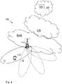
- Figure 4 is a schematic overview depicting a wireless communications network 100.
- the wireless communications network 100 comprises one or more RANs and one or more CNs.
- the wireless communications network 100 may use a number of different technologies, such as Wi-Fi, Long Term Evolution (LTE), LTE-Advanced, 5G, New Radio (NR), Wideband Code Division Multiple Access (WCDMA), Global System for Mobile communications/enhanced Data rate for GSM Evolution (GSM/EDGE), Worldwide Interoperability for Microwave Access (WiMax), or Ultra Mobile Broadband (UMB), just to mention a few possible implementations.
- LTE Long Term Evolution
- NR New Radio
- WCDMA Wideband Code Division Multiple Access
- GSM/EDGE Global System for Mobile communications/enhanced Data rate for GSM Evolution
- WiMax Worldwide Interoperability for Microwave Access
- UMB Ultra Mobile Broadband
- Embodiments herein relate to recent technology trends that are of particular interest in
- UEs such as a wireless communications device 120 operate.
- the UE 120 may be a mobile station, a non-access point (non-AP) STA, a STA, a wireless terminals, and is capable to communicate via one or more Access Networks (AN), e.g. RAN, to one or more core networks (CN).
- AN Access Networks
- CN core networks
- wireless communications device is a non-limiting term which means any terminal, wireless communication terminal, user equipment, Machine Type Communication (MTC) device, Device to Device (D2D) terminal, or node e.g. smart phone, laptop, mobile phone, sensor, relay, mobile tablets or even a small base station communicating within a cell.
- MTC Machine Type Communication
- D2D Device to Device
- the wireless communications network 100 comprises one or more radio network nodes such as a network node 110 e.g. comprising one or more DUs and one or more CUs a.
- the radio network node 110 e.g. provides multiple Public Land Mobile Networks (PLMNs) and where each radio network node also provide radio coverage over a respective geographical area referred to as one or more cells 11, 12, which may also be referred to as a beam or a beam group of a first radio access technology (RAT), such as 5G, LTE, Wi-Fi or similar.
- PLMNs Public Land Mobile Networks
- RAT radio access technology
- the network node 110 may be a NG-RAN node, a transmission and reception point e.g.
- a base station a radio access network node such as a Wireless Local Area Network (WLAN) access point or an Access Point Station (AP STA), an access controller, a base station, e.g. a radio base station such as a NodeB, an evolved Node B (eNB, eNode B), a gNB, a base transceiver station, a radio remote unit, an Access Point Base Station, a base station router, a transmission arrangement of a radio base station, a stand-alone access point or any other network unit capable of communicating with the wireless communications device 120 within the service area served by the network node 110 depending e.g. on the first radio access technology and terminology used.
- a radio base station e.g. a radio base station such as a NodeB, an evolved Node B (eNB, eNode B), a gNB, a base transceiver station, a radio remote unit, an Access Point Base Station, a base station router, a transmission arrangement of a radio base station,
- Methods herein may be performed by the network node 110 such as e.g. its DU.
- any Distributed Node (DN) and functionality e.g. comprised in a cloud 140 as shown in Figure 4 , may be used for performing or partly performing the methods.
- the network aspects of embodiments herein may be deployed in a cloud environment.
- Figure 5 shows an example method performed by a network node 110 e.g. a DU, or comprising a DU, for e.g. transmission of a PDCP PDU, to the wireless communications device 120.
- the network node 110 and the wireless communications device 120 operate in the wireless communications network 100, e.g. a communications network providing dual connectivity or a communications network wherein PDCP and lower layers are in different nodes or possibly in different software functions.
- the method may comprise any of the actions below.
- the network node 110 may receive a PDCP PDU from the CU and in Action502 determine whether the received PDCP PDU is a first time transmitted PDCP PDU or a retransmitted PDCP PDU.
- the network node 110 may then arrange a determined received first time transmitted PDCP PDU last in the first set of PDCP PDUs wherein the first set of PDCP PDUs is a first time transmission queue and in Action 504, arrange a determined received retransmitted PDCP PDU last in the second set of PDCP PDUs, wherein the second set of PDCP PDUs is a retransmission queue
- the network node 110 orders (also referred to as arranges or puts) a number of PDCP PDUs in a numerical order based on their respective PDCP Sequence Number (SN).
- the number of PDCP PDUs are taken from a first set of PDCP PDUs comprising one or more first time transmitted PDCP PDUs, and from a second set of PDCP PDUs comprising one or more retransmitted PDCP PDUs.
- the one or more first time transmitted PDCP PDUs and the one or more retransmitted PDCP PDUs are received from a controlling node, e.g. a Central Unit (CU)
- the CU may e.g. be comprised in the network node 110 or be connected to the network node 110.
- the CU operate in the wireless communications network 100.
- the network node 110 transmits the number of the PDCP PDUs in the numerical order to the wireless communications device (120).
- the PDCP PDU may comprise an indication, e.g. a flag, indicating whether the PDCP PDU is first time transmitted or retransmitted.
- the method is performed by the network node 110 for transmission of a PDCP PDU to the wireless communications device 120.
- the network node 110 and the wireless communications device 120 operate in a wireless communications network 100.
- the network node 110 may be represented by a DU or may comprise a DU.
- the wireless communications network 100 may relates to any one out of: A communications network providing dual connectivity, or a communications network wherein PDCP and lower layers are in different nodes or in different software functions.
- the network node 110 will arrange a reordering of first time transmission PDCU PDUs and retransmitted PDCP PDUs so that the PDUs can be transmitted to the UE in correct PDCP SN order with improved end user performance as a result.
- the network node 110 receives e.g. from a CU, PDCP PDUs that is to be transmitted to the wireless communications device 120.
- the received PDCP PDUs are a mix of first time transmitted PDCP PDUs and a retransmitted PDCP PDUs.
- the method comprises the following actions which may be taken in any suitable order.
- Optional actions are marked as dashed boxes in Figure 5 .
- optional actions 501-504 are taken for each of a number of PDCP PDUs:
- the network node 110 receives a PDCP PDU, e.g. comprising one or more PDCP PDUs, from the CU.
- a PDCP PDU e.g. comprising one or more PDCP PDUs
- the received PDCP PDUs are a mix of first time transmitted PDCP PDUs and retransmitted PDCP PDUs, so e.g. for each received PDCP PDU, the network node 110 determines whether the received PDCP PDU is a first time transmitted PDCP PDU or a retransmitted PDCP PDU.
- Every PDCP PDU may besides a PDCP SN also include a so called a NR- User plane (U) SN.
- NR-U SN may only be used to identify the order of the packets sent over the Transport Network (TN) between CU and DU or between eNB and gNB.
- the received PDCP PDUs may in some embodiments first be reordered according to NR-U SN order before determining whether the received PDCP PDU is a first time transmitted PDCP PDU or a retransmitted PDCP PDU.
- the network node 110 arranges a determined received first time transmitted PDCP PDU last in the first set of PDCP PDUs, wherein the first set of PDCP PDUs is a first time transmission queue. Thus network node 110 arranges each of the determined received first time transmitted PDCP PDU out of the received PDCP PDUs, last in the first set of PDCP PDUs, i.e. in the first time transmission queue.
- the network node 110 arranges a determined received retransmitted PDCP PDU last in the second set of PDCP PDUs, wherein the second set of PDCP PDUs is a retransmission queue.
- network node 110 arranges each of the determined received retransmitted PDCP PDU out of the received PDCP PDUs, last in the second set of PDCP PDUs, i.e. in the retransmission queue.
- the network node 110 analyses the PDCP SN of the received PDCP PDUs in both the first time transmission queue, and the retransmission queue.
- the network node 110 then arranges a number of PDCP PDUs in a numerical order based on their respective PDCP SN. This is also referred to as reordering of first time transmission PDCU PDUs and retransmitted PDCP PDUs into a new queue.
- the number of PDCP PDUs referred to here relates to the received PDCP PDUs which are divided into the first time transmission and retransmission queues.
- the number of PDCP PDUs is taken from the first set of PDCP PDUs comprising one or more first time transmitted PDCP PDUs and from the second set of PDCP PDUs comprising one or more retransmitted PDCP PDUs.
- the one or more first time transmitted PDCP PDUs and the one or more retransmitted PDCP PDUs are received from the controlling node.
- the controlling node may be represented by a CU, which CU may be comprised in the network node 110 or may be connected to the network node 110 and is operating in the wireless communications network 100.
- a PDCP PDU received from the CU may comprise an indication, e.g. a flag, indicating whether the PDCP PDU is first time transmitted or retransmitted.
- the arranging of the number of PDCP PDUs in a numerical order based on their respective PDCP SN is triggered at a selected event.
- the selected event may e.g. comprise anyone or more out of: A retransmitted PDCP PDU arrives to an empty retransmission queue, a preconfigured time at which time a predefined number of PDUs have arrived in the Retransmission queue, when a predefined number of PDCP PDUs have arrived in the Retransmission queue, and when there are PDCP PDU(s) in the Retransmission queue.
- the network node 110 may arrange the number of PDCP PDUs in a numerical order based on their respective PDCP SN by reallocating the analysed PDUs in a new queue, based on PDCP SN of each PDU.
- the network node 110 then transmits the number of the PDCP PDUs in the numerical order to the wireless communications device 120.
- the PDUs can be transmitted to the UE in correct PDCP SN order with improved end user performance as a result.
- PDUs in the example below are referred to as PDUs for simplicity.
- PDUs arriving to the network node 110 will be assigned to one queue each:
- the PDU reordering in the DU is triggered.
- the network node 110 such as its DU reordering the PDUs, may analyse the PDCP SN of the PDUs in both first time transmission and the Retransmission queues and reallocates the PDUs in a new queue, this time based on PDCP SN of each PDU.
- the Radio Link Control (RLC), Medium Access Control (MAC), scheduling or similar entity will at scheduling take PDUs from the new queue with reordered PDUs, why all PDUs on the leg are sent in order towards the UE 120.
- RLC Radio Link Control
- MAC Medium Access Control
- the network node 110 arranging the number of PDCP PDUs in a numerical order based on their respective PDCP SN comprises that an RLC, MAC, scheduling or similar entity in the network node 110 may schedule PDUs immediately from the initial 2 queues in the same fashion and not create a new queue.
- Hybrid Automatic Repeat Request (HARQ) and RLC retransmissions may impact that not every PDU arrives in that order to the UE 120.
- Embodiments herein may apply both to DC and not DC but using a split node. I.e. any scenario when PDCP and lower layers are in different nodes or possibly software (SW) function.
- SW software
- Examples herein have focus on DC because this is the most likely scenario: e.g. when there is ongoing transmission on 2 legs and one leg suddenly performs badly, Leading to retransmissions of PDUS to the other leg. However, possibly this may happen at single leg transmission, but once again, this is much more unlikely.
- Figure 7 a and b shows an example of arrangements in the network node 110.
- the network node 110 may comprise an input and output interface 700 configured to communicate with each other.
- the input and output interface may comprise a wireless receiver (not shown) and a wireless transmitter (not shown).
- the network node 110 may comprise a receiving unit 710, an arranging unit 720, a determining unit 730 and a transmitting unit 740 to perform the method actions as described herein.
- the embodiments herein may be implemented through a respective processor or one or more processors, such as the processor 750 of a processing circuitry in the network node 110 depicted in Figure 7a , together with respective computer program code for performing the functions and actions of the embodiments herein.
- the program code mentioned above may also be provided as a computer program product, for instance in the form of a data carrier carrying computer program code for performing the embodiments herein when being loaded into the network node 110.
- One such carrier may be in the form of a CD ROM disc. It is however feasible with other data carriers such as a memory stick.
- the computer program code may furthermore be provided as pure program code on a server and downloaded to the network node 110.
- the network node 110 may further comprise respective a memory 760 comprising one or more memory units.
- the memory comprises instructions executable by the processor in network node 110.
- the memory is arranged to be used to store instructions, PDUs, data, parameters, configurations, and applications to perform the methods herein when being executed in the network node 110.
- are computer program 770 comprises instructions, which when executed by the at least one processor 750, cause the at least one processor 750 of the network node 110 to perform the actions above.
- a respective carrier 780 comprises the computer program 770, wherein the carrier 780 is one of an electronic signal, an optical signal, an electromagnetic signal, a magnetic signal, an electric signal, a radio signal, a microwave signal, or a computer-readable storage medium.
- the functional units in the network node 110 may refer to a combination of analog and digital circuits, and/or one or more processors configured with software and/or firmware, e.g. stored in the UE 120, that when executed by the respective one or more processors such as the processors described above cause the respective at least one processor to perform actions according to any of the actions above.
- processors as well as the other digital hardware, may be included in a single Application-Specific Integrated Circuitry (ASIC), or several processors and various digital hardware may be distributed among several separate components, whether individually packaged or assembled into a system-on-a-chip (SoC).
- ASIC Application-Specific Integrated Circuitry
- SoC system-on-a-chip
- a communication system includes a telecommunication network 3210 such as the wireless communications network 100, e.g. an loT network, or a WLAN, such as a 3GPP-type cellular network, which comprises an access network 3211, such as a radio access network, and a core network 3214.
- the access network 3211 comprises a plurality of base stations 3212a, 3212b, 3212c, such as the network node 110, 130, access nodes, AP STAs NBs, eNBs, gNBs or other types of wireless access points, each defining a corresponding coverage area 3213a, 3213b, 3213c.
- Each base station 3212a, 3212b, 3212c is connectable to the core network 3214 over a wired or wireless connection 3215.
- a first user equipment (UE) e.g. the UE 120 such as a Non-AP STA 3291 located in coverage area 3213c is configured to wirelessly connect to, or be paged by, the corresponding base station 3212c.
- a second UE 3292 e.g. the wireless device 122 such as a Non-AP STA in coverage area 3213a is wirelessly connectable to the corresponding base station 3212a. While a plurality of UEs 3291, 3292 are illustrated in this example, the disclosed embodiments are equally applicable to a situation where a sole UE is in the coverage area or where a sole UE is connecting to the corresponding base station 3212.
- the telecommunication network 3210 is itself connected to a host computer 3230, which may be embodied in the hardware and/or software of a standalone server, a cloud-implemented server, a distributed server or as processing resources in a server farm.
- the host computer 3230 may be under the ownership or control of a service provider, or may be operated by the service provider or on behalf of the service provider.
- the connections 3221, 3222 between the telecommunication network 3210 and the host computer 3230 may extend directly from the core network 3214 to the host computer 3230 or may go via an optional intermediate network 3220.
- the intermediate network 3220 may be one of, or a combination of more than one of, a public, private or hosted network; the intermediate network 3220, if any, may be a backbone network or the Internet; in particular, the intermediate network 3220 may comprise two or more sub-networks (not shown).
- the communication system of Figure 8 as a whole enables connectivity between one of the connected UEs 3291, 3292 and the host computer 3230.
- the connectivity may be described as an over-the-top (OTT) connection 3250.
- the host computer 3230 and the connected UEs 3291, 3292 are configured to communicate data and/or signaling via the OTT connection 3250, using the access network 3211, the core network 3214, any intermediate network 3220 and possible further infrastructure (not shown) as intermediaries.
- the OTT connection 3250 may be transparent in the sense that the participating communication devices through which the OTT connection 3250 passes are unaware of routing of uplink and downlink communications.
- a base station 3212 may not or need not be informed about the past routing of an incoming downlink communication with data originating from a host computer 3230 to be forwarded (e.g., handed over) to a connected UE 3291. Similarly, the base station 3212 need not be aware of the future routing of an outgoing uplink communication originating from the UE 3291 towards the host computer 3230.
- a host computer 3310 comprises hardware 3315 including a communication interface 3316 configured to set up and maintain a wired or wireless connection with an interface of a different communication device of the communication system 3300.
- the host computer 3310 further comprises processing circuitry 3318, which may have storage and/or processing capabilities.
- the processing circuitry 3318 may comprise one or more programmable processors, application-specific integrated circuits, field programmable gate arrays or combinations of these (not shown) adapted to execute instructions.
- the host computer 3310 further comprises software 3311, which is stored in or accessible by the host computer 3310 and executable by the processing circuitry 3318.
- the software 3311 includes a host application 3312.
- the host application 3312 may be operable to provide a service to a remote user, such as a UE 3330 connecting via an OTT connection 3350 terminating at the UE 3330 and the host computer 3310. In providing the service to the remote user, the host application 3312 may provide user data which is transmitted using the OTT connection 3350.
- the communication system 3300 further includes a base station 3320 provided in a telecommunication system and comprising hardware 3325 enabling it to communicate with the host computer 3310 and with the UE 3330.
- the hardware 3325 may include a communication interface 3326 for setting up and maintaining a wired or wireless connection with an interface of a different communication device of the communication system 3300, as well as a radio interface 3327 for setting up and maintaining at least a wireless connection 3370 with a UE 3330 located in a coverage area (not shown) served by the base station 3320.
- the communication interface 3326 may be configured to facilitate a connection 3360 to the host computer 3310.
- connection 3360 may be direct or it may pass through a core network (not shown in Figure 9 ) of the telecommunication system and/or through one or more intermediate networks outside the telecommunication system.
- the hardware 3325 of the base station 3320 further includes processing circuitry 3328, which may comprise one or more programmable processors, application-specific integrated circuits, field programmable gate arrays or combinations of these (not shown) adapted to execute instructions.
- the base station 3320 further has software 3321 stored internally or accessible via an external connection.
- the communication system 3300 further includes the UE 3330 already referred to.
- Its hardware 3335 may include a radio interface 3337 configured to set up and maintain a wireless connection 3370 with a base station serving a coverage area in which the UE 3330 is currently located.
- the hardware 3335 of the UE 3330 further includes processing circuitry 3338, which may comprise one or more programmable processors, application-specific integrated circuits, field programmable gate arrays or combinations of these (not shown) adapted to execute instructions.
- the UE 3330 further comprises software 3331, which is stored in or accessible by the UE 3330 and executable by the processing circuitry 3338.
- the software 3331 includes a client application 3332.
- the client application 3332 may be operable to provide a service to a human or non-human user via the UE 3330, with the support of the host computer 3310.
- an executing host application 3312 may communicate with the executing client application 3332 via the OTT connection 3350 terminating at the UE 3330 and the host computer 3310.
- the client application 3332 may receive request data from the host application 3312 and provide user data in response to the request data.
- the OTT connection 3350 may transfer both the request data and the user data.
- the client application 3332 may interact with the user to generate the user data that it provides.
- the host computer 3310, base station 3320 and UE 3330 illustrated in Figure 9 may be identical to the host computer 3230, one of the base stations 3212a, 3212b, 3212c and one of the UEs 3291, 3292 of Figure 10 , respectively.
- the inner workings of these entities may be as shown in Figure 9 and independently, the surrounding network topology may be that of Figure 8 .
- the OTT connection 3350 has been drawn abstractly to illustrate the communication between the host computer 3310 and the use equipment 3330 via the base station 3320, without explicit reference to any intermediary devices and the precise routing of messages via these devices.
- Network infrastructure may determine the routing, which it may be configured to hide from the UE 3330 or from the service provider operating the host computer 3310, or both. While the OTT connection 3350 is active, the network infrastructure may further take decisions by which it dynamically changes the routing (e.g., on the basis of load balancing consideration or reconfiguration of the network).
- the wireless connection 3370 between the UE 3330 and the base station 3320 is in accordance with the teachings of the embodiments described throughout this disclosure.
- One or more of the various embodiments improve the performance of OTT services provided to the UE 3330 using the OTT connection 3350, in which the wireless connection 3370 forms the last segment. More precisely, the teachings of these embodiments may improve the applicable RAN effect: data rate, latency, power consumption, and thereby provide benefits such as corresponding effect on the OTT service: e.g. reduced user waiting time, relaxed restriction on file size, better responsiveness, extended battery lifetime.
- a measurement procedure may be provided for the purpose of monitoring data rate, latency and other factors on which the one or more embodiments improve.
- the measurement procedure and/or the network functionality for reconfiguring the OTT connection 3350 may be implemented in the software 3311 of the host computer 3310 or in the software 3331 of the UE 3330, or both.
- sensors (not shown) may be deployed in or in association with communication devices through which the OTT connection 3350 passes; the sensors may participate in the measurement procedure by supplying values of the monitored quantities exemplified above, or supplying values of other physical quantities from which software 3311, 3331 may compute or estimate the monitored quantities.
- the reconfiguring of the OTT connection 3350 may include message format, retransmission settings, preferred routing etc.; the reconfiguring need not affect the base station 3320, and it may be unknown or imperceptible to the base station 3320. Such procedures and functionalities may be known and practiced in the art.
- measurements may involve proprietary UE signaling facilitating the host computer's 3310 measurements of throughput, propagation times, latency and the like.
- the measurements may be implemented in that the software 3311, 3331 causes messages to be transmitted, in particular empty or 'dummy' messages, using the OTT connection 3350 while it monitors propagation times, errors etc.
- FIG 10 is a flowchart illustrating a method implemented in a communication system, in accordance with one embodiment.
- the communication system includes a host computer, a base station such as the network node 110, and a UE such as the UE 120, which may be those described with reference to Figure 8 and Figure 9 .
- a first action 3410 of the method the host computer provides user data.
- the host computer provides the user data by executing a host application.
- the host computer initiates a transmission carrying the user data to the UE.
- the base station transmits to the UE the user data which was carried in the transmission that the host computer initiated, in accordance with the teachings of the embodiments described throughout this disclosure.
- the UE executes a client application associated with the host application executed by the host computer.
- FIG 11 is a flowchart illustrating a method implemented in a communication system, in accordance with one embodiment.
- the communication system includes a host computer, a base station such as a AP STA, and a UE such as a Non-AP STA which may be those described with reference to Figure 8 and Figure 9 .
- a first action 3510 of the method the host computer provides user data.
- the host computer provides the user data by executing a host application.
- the host computer initiates a transmission carrying the user data to the UE. The transmission may pass via the base station, in accordance with the teachings of the embodiments described throughout this disclosure.
- the UE receives the user data carried in the transmission.
- FIG 12 is a flowchart illustrating a method implemented in a communication system, in accordance with one embodiment.
- the communication system includes a host computer, a base station such as a AP STA, and a UE such as a Non-AP STA which may be those described with reference to Figure 8 and Figure 9 .
- a first action 3610 of the method the UE receives input data provided by the host computer.
- the UE provides user data.
- the UE provides the user data by executing a client application.
- the UE executes a client application which provides the user data in reaction to the received input data provided by the host computer.
- the executed client application may further consider user input received from the user.
- the UE initiates, in an optional third subaction 3630, transmission of the user data to the host computer.
- the host computer receives the user data transmitted from the UE, in accordance with the teachings of the embodiments described throughout this disclosure.
- FIG. 13 is a flowchart illustrating a method implemented in a communication system, in accordance with one embodiment.
- the communication system includes a host computer, a base station such as a AP STA, and a UE such as a Non-AP STA which may be those described with reference to Figure 8 and Figure 9 .
- a first action 3710 of the method in accordance with the teachings of the embodiments described throughout this disclosure, the base station receives user data from the UE.
- the base station initiates transmission of the received user data to the host computer.
- the host computer receives the user data carried in the transmission initiated by the base station.
Landscapes
- Engineering & Computer Science (AREA)
- Computer Networks & Wireless Communication (AREA)
- Signal Processing (AREA)
- Computer Security & Cryptography (AREA)
- Mobile Radio Communication Systems (AREA)
Claims (20)
- Procédé réalisé par un nœud de réseau (110) pour une transmission d'une unité de données de protocole, PDU, de protocole de convergence de données en paquets, PDCP, à un dispositif de communication sans fil (120), dans lequel le nœud de réseau (110) et le dispositif de communication sans fil (120) fonctionnent dans un réseau de communication sans fil (100), le procédé comprenant :l'agencement (505b) d'un nombre de PDU PDCP dans un ordre numérique sur la base de leur numéro de séquence, SN, PDCP respectif, dans lequel le nombre de PDU PDCP sont prises dans un premier ensemble de PDU PDCP comprenant une ou plusieurs PDU PDCP transmises pour la première fois, et dans un deuxième ensemble de PDU PDCP comprenant une ou plusieurs PDU PDCP retransmises, et dans lequel les une ou plusieurs PDU PDCP transmises pour la première fois et les une ou plusieurs PDU PDCP retransmises sont reçues depuis un nœud de commande ;la transmission (506) du nombre de PDU PDCP dans l'ordre numérique au dispositif de communication sans fil (120) .
- Procédé selon la revendication 1, dans lequel le nœud de commande est représenté par une unité centrale, CU, ladite CU étant comprise dans le nœud de réseau (110) ou étant reliée au nœud de réseau (110) et fonctionnant dans le réseau de communication sans fil (100).
- Procédé selon la revendication 1 ou 2, dans lequel l'agencement (505b) du nombre de PDU PDCP dans un ordre numérique sur la base de leur SN PDCP respectif est déclenché à un événement sélectionné comprenant l'un quelconque ou plusieurs parmi :une PDU PDCP retransmise arrive à une file d'attente de retransmissions vide,un temps préconfiguré auquel un nombre prédéfini de PDU sont arrivées dans la file d'attente de retransmission,lorsqu'un nombre prédéfini de PDU PDCP sont arrivées dans la file d'attente de retransmission, etlorsqu'il y a une ou plusieurs PDU PDCP dans la file d'attente de retransmission.
- Procédé selon l'une quelconque des revendications 1 à 3, comprenant en outre :la réception (501) d'une PDU PDCP depuis la CU,la détermination (502) si la PDU PDCP reçue est une PDU PDCP transmise pour la première fois ou une PDU PDCP retransmise,l'agencement (503) d'une PDU PDCP transmise pour la première fois reçue déterminée en dernier dans le premier ensemble de PDU PDCP, dans lequel le premier ensemble de PDU PDCP est une file d'attente de transmission pour la première fois, etl'agencement (504) d'une PDU PDCP retransmise reçue déterminée en dernier dans le deuxième ensemble de PDU PDCP, dans lequel le deuxième ensemble de PDU PDCP est une file d'attente de retransmission
- Procédé selon l'une quelconque des revendications 1 à 4, comprenant en outre :l'analyse (505a) du SN PDCP de PDU PDCP dans à la fois une file d'attente de transmission pour la première fois et une file d'attente de retransmission.
- Procédé selon la revendication 5, dans lequel l'agencement (505b) du nombre de PDU PDCP dans un ordre numérique sur la base de leur SN PDCP respectif comprend la réallocation des PDU analysées dans une nouvelle file d'attente, sur la base du SN PDCP de chaque PDU.
- Procédé selon l'une quelconque des revendications 1 à 6, dans lequel une PDU PDCP reçue depuis la CU comprend une indication indiquant si la PDU PDCP est transmise pour la première fois ou retransmise.
- Procédé selon l'une quelconque des revendications 1 à 7, dans lequel le nœud de réseau (110) est représenté par une unité distribuée, DU, ou comprend une DU.
- Procédé selon l'une quelconque des revendications 1 à 8, dans lequel le réseau de communication sans fil (100) concerne l'un quelconque parmi :- un réseau de communication fournissant une connectivité double, ou- un réseau de communication dans lequel PDCP et des couches inférieures sont dans des nœuds différents ou dans des fonctions logicielles différentes.
- Programme informatique (770) comprenant des instructions qui, lorsqu'elles sont exécutées par un processeur (750), amènent le processeur (750) à réaliser des actions selon l'une quelconque des revendications 1 à 9.
- Porteuse (780) comprenant le programme informatique (770) selon la revendication 10, dans lequel la porteuse (780) est l'un parmi un signal électronique, un signal optique, un signal électromagnétique, un signal magnétique, un signal électrique, un signal radio, un signal micro-ondes ou un support de stockage lisible par ordinateur.
- Nœud de réseau (110) pour une transmission d'une unité de données de protocole, PDU, de protocole de convergence de données en paquets, PDCP, à un dispositif de communication sans fil (120), dans lequel le nœud de réseau (110) et le dispositif de communication sans fil (120) sont configurés pour fonctionner dans un réseau de communication sans fil (100), dans lequel le nœud de réseau (110) est en outre configuré pour :- agencer un nombre de PDU PDCP dans un ordre numérique sur la base de leur numéro de séquence, SN, PDCP respectif, dans lequel le nombre de PDU PDCP sont prises dans un premier ensemble de PDU PDCP comprenant une ou plusieurs PDU PDCP transmises pour la première fois, et dans un deuxième ensemble de PDU PDCP comprenant une ou plusieurs PDU PDCP retransmises, et dans lequel les une ou plusieurs PDU PDCP transmises pour la première fois et les une ou plusieurs PDU PDCP retransmises sont reçues depuis un nœud de commande, et- transmettre le nombre de PDU PDCP dans l'ordre numérique au dispositif de communication sans fil (120) .
- Nœud de réseau (110) selon la revendication 12, dans lequel le nœud de commande est représenté par une unité centrale, CU, ladite CU étant apte à être comprise dans le nœud de réseau (110) ou étant apte à être reliée au nœud de réseau (110) et à fonctionner dans le réseau de communication sans fil (100).
- Nœud de réseau (110) selon la revendication 12 ou 13, étant en outre configuré pour agencer le nombre de PDU PDCP dans un ordre numérique sur la base de leur SN PDCP respectif lorsqu'il est déclenché à un événement sélectionné comprenant l'un quelconque ou plusieurs parmi :une PDU PDCP retransmise arrive à une file d'attente de retransmissions vide,un temps préconfiguré auquel un nombre prédéfini de PDU sont arrivées dans la file d'attente de retransmission,lorsqu'un nombre prédéfini de PDU PDCP sont arrivées dans la file d'attente de retransmission, etlorsqu'il y a une ou plusieurs PDU PDCP dans la file d'attente de retransmission.
- Nœud de réseau (110) selon l'une quelconque des revendications 12 à 14, étant en outre configuré pour :- recevoir, depuis la CU, une PDU PDCP ;- déterminer si la PDU PDCP reçue est une PDU PDCP transmise pour la première fois ou une PDU PDCP retransmise ;- agencer une PDU PDCP transmise pour la première fois reçue déterminée en dernier dans le premier ensemble de PDU PDCP, dans lequel le premier ensemble de PDU PDCP est une file d'attente de transmission pour la première fois, et- agencer une PDU PDCP retransmise reçue déterminée en dernier dans le deuxième ensemble de PDU PDCP, dans lequel le deuxième ensemble de PDU PDCP est une file d'attente de retransmission
- Nœud de réseau (110) selon l'une quelconque des revendications 12 à 15, étant en outre configuré pour :
analyser le SN PDCP de PDU PDCP dans à la fois une file d'attente de transmission pour la première fois et une file d'attente de retransmission. - Nœud de réseau (110) selon la revendication 16, étant en outre configuré pour agencer le nombre de PDU PDCP dans un ordre numérique sur la base de leur SN PDCP respectif par la réallocation des PDU analysées dans une nouvelle file d'attente, sur la base du SN PDCP de chaque PDU.
- Nœud de réseau (110) selon l'une quelconque des revendications 12 à 17, dans lequel la PDU PDCP est configurée pour comprendre une indication indiquant si la PDU PDCP est transmise pour la première fois ou retransmise.
- Nœud de réseau (110) selon l'une quelconque des revendications 12 à 18, dans lequel le nœud de réseau (110) est apte à être représenté par une unité distribuée, DU, ou comprend une DU.
- Nœud de réseau (110) selon l'une quelconque des revendications 12 à 19, dans lequel le réseau de communication sans fil (100) est apte à concerner l'un quelconque parmi :- un réseau de communication fournissant une connectivité double, ou- un réseau de communication dans lequel PDCP et des couches inférieures sont aptes à être dans des nœuds différents ou dans des fonctions logicielles différentes.
Applications Claiming Priority (2)
| Application Number | Priority Date | Filing Date | Title |
|---|---|---|---|
| US201862742494P | 2018-10-08 | 2018-10-08 | |
| PCT/SE2019/050892 WO2020076208A1 (fr) | 2018-10-08 | 2019-09-19 | Nœud de réseau et procédé dans un réseau de communications sans fil |
Publications (3)
| Publication Number | Publication Date |
|---|---|
| EP3864930A1 EP3864930A1 (fr) | 2021-08-18 |
| EP3864930A4 EP3864930A4 (fr) | 2021-12-22 |
| EP3864930B1 true EP3864930B1 (fr) | 2022-05-25 |
Family
ID=70164730
Family Applications (1)
| Application Number | Title | Priority Date | Filing Date |
|---|---|---|---|
| EP19871680.5A Not-in-force EP3864930B1 (fr) | 2018-10-08 | 2019-09-19 | Noeud de réseau et procédé dans un réseau de communications sans fil |
Country Status (4)
| Country | Link |
|---|---|
| US (1) | US11646835B2 (fr) |
| EP (1) | EP3864930B1 (fr) |
| CN (1) | CN112771992A (fr) |
| WO (1) | WO2020076208A1 (fr) |
Families Citing this family (2)
| Publication number | Priority date | Publication date | Assignee | Title |
|---|---|---|---|---|
| WO2020092357A1 (fr) * | 2018-11-01 | 2020-05-07 | Apple Inc. | Amélioration de commande de flux de plan d'utilisateur pour des paquets retransmis |
| KR102750786B1 (ko) * | 2018-11-02 | 2025-01-06 | 지티이 코포레이션 | 데이터 송신 및 측정 기술들 |
Family Cites Families (16)
| Publication number | Priority date | Publication date | Assignee | Title |
|---|---|---|---|---|
| US5222061A (en) * | 1991-10-31 | 1993-06-22 | At&T Bell Laboratories | Data services retransmission procedure |
| WO2001099355A1 (fr) * | 2000-06-23 | 2001-12-27 | Mitsubishi Denki Kabushiki Kaisha | Procede et systeme de retransmission de paquets |
| SE0100739D0 (sv) * | 2001-02-28 | 2001-02-28 | Ericsson Telefon Ab L M | Method and system of retransmission |
| KR100765121B1 (ko) * | 2001-11-24 | 2007-10-11 | 엘지전자 주식회사 | 송신버퍼의 프로토콜 데이터 유닛 폴링 방법 |
| US9144038B2 (en) * | 2010-11-05 | 2015-09-22 | Samsung Electronics Co., Ltd. | Method and apparatus for calculating power headroom in carrier aggregation mobile communication system |
| JP5532152B2 (ja) * | 2013-01-04 | 2014-06-25 | 富士通株式会社 | 無線通信システム、移動局及び基地局 |
| CN104935413B (zh) | 2014-03-19 | 2019-12-27 | 夏普株式会社 | 分组数据汇聚协议pdcp实体及其执行的方法 |
| US10028311B2 (en) * | 2014-04-22 | 2018-07-17 | Lg Electronics Inc. | Method for processing received PDCP PDUs for D2D communication system and device therefor |
| US9838282B2 (en) * | 2014-05-09 | 2017-12-05 | Telefonaktiebolaget Lm Ericsson (Publ) | PDCP and flow control for split bearer |
| US10397754B2 (en) * | 2015-08-06 | 2019-08-27 | Qualcomm Incorporation | Packet data convergence protocol reordering with enhanced component carriers |
| US9999049B2 (en) * | 2015-08-31 | 2018-06-12 | Qualcomm Incorporated | Avoiding unnecessary protocol data unit (PDU) transmissions |
| CN108353307B (zh) * | 2015-11-04 | 2021-07-09 | 瑞典爱立信有限公司 | 在分割承载环境下提供流控制的方法、系统和设备 |
| US11129233B2 (en) * | 2016-04-01 | 2021-09-21 | Intel Corporation | User equipment (UE), evolved node-b (ENB) and methods for a packet convergence and link control (PCLC) layer |
| EP4429296A3 (fr) | 2016-08-09 | 2024-12-11 | Samsung Electronics Co., Ltd | Procédé et appareil de gestion de fonctionnement de plan utilisateur dans un système de communication sans fil |
| US10812230B2 (en) * | 2018-01-19 | 2020-10-20 | Kt Corporation | Method and apparatus for controlling data transmission using interworking interface between NR and LTE base station |
| US10819473B2 (en) * | 2018-08-01 | 2020-10-27 | Charter Communications Operating, Llc | Disabling, using a designated process, hybrid automatic repeat request (HARQ) acknowledgments for packets for which acknowledgements are supported at network or higher layer |
-
2019
- 2019-09-19 WO PCT/SE2019/050892 patent/WO2020076208A1/fr not_active Ceased
- 2019-09-19 CN CN201980066317.6A patent/CN112771992A/zh active Pending
- 2019-09-19 EP EP19871680.5A patent/EP3864930B1/fr not_active Not-in-force
- 2019-09-19 US US17/283,579 patent/US11646835B2/en active Active
Also Published As
| Publication number | Publication date |
|---|---|
| EP3864930A1 (fr) | 2021-08-18 |
| EP3864930A4 (fr) | 2021-12-22 |
| US20210385027A1 (en) | 2021-12-09 |
| US11646835B2 (en) | 2023-05-09 |
| WO2020076208A1 (fr) | 2020-04-16 |
| CN112771992A (zh) | 2021-05-07 |
Similar Documents
| Publication | Publication Date | Title |
|---|---|---|
| US12089276B2 (en) | Alternate path information exchange for better scheduling and backhaul failure recovery in integrated access backhaul networks | |
| EP3925173A1 (fr) | Unité centrale (cu), unité distribuée (du) et procédés associés pour l'acheminement de données dans un réseau de raccordement d'accès intégré (iab) | |
| US11864022B2 (en) | Buffer status reporting in wireless communication systems | |
| US11483890B2 (en) | First unit, second unit and methods in a wireless communications network | |
| US20190312693A1 (en) | A Wireless Device, a Network Node and Methods Therein for Transmission of Synchronization Signals | |
| US20220159506A1 (en) | Communication Node and Method Performed Therein for Handling Communication Using Different BSR Formats | |
| WO2022005346A1 (fr) | Procédé de planification multiples flux de données répliquées sur un certain nombre de voies de transmission sans fil | |
| JP7074852B2 (ja) | 通信を取り扱うためのtr送信デバイスおよびその中で実行される方法 | |
| US11924683B2 (en) | Network node and method in a wireless communications network | |
| EP3864930B1 (fr) | Noeud de réseau et procédé dans un réseau de communications sans fil | |
| US20200092045A1 (en) | Radio Node and Methods in a Wireless Communications Network | |
| WO2019182500A1 (fr) | Première unité, unité distribuée et procédés d'adaptation de débit de transmission dans un réseau de communication sans fil | |
| US20250234218A1 (en) | Network Nodes and Methods in a Wireless Communications Network Technical Field | |
| EP4233422B1 (fr) | Priorisation de canal logique | |
| US12414011B2 (en) | Subscriber's data node, serving node, exposure function node and methods in a communications network | |
| US20240292287A1 (en) | Steering data traffic in communication with user equipment in a wireless communications network | |
| US11601858B2 (en) | Relocation of a user equipment connection from a source radio network controller RNC to a target RNC initiated via a core network | |
| WO2023003498A1 (fr) | Nœud de réseau et procédé mis en œuvre dans celui-ci pour gérer la configuration d'une connexion de données pour un équipement utilisateur | |
| US11902964B2 (en) | Network node and method performed therein for scheduling user equipment in uplink | |
| US20250119898A1 (en) | Network node and method therein | |
| WO2023063855A1 (fr) | Dispositif sans fil et procédé dans un réseau de communication sans fil | |
| CN118303070A (zh) | 无线通信网络中的ue、无线电网络节点和所执行的方法 |
Legal Events
| Date | Code | Title | Description |
|---|---|---|---|
| STAA | Information on the status of an ep patent application or granted ep patent |
Free format text: STATUS: THE INTERNATIONAL PUBLICATION HAS BEEN MADE |
|
| PUAI | Public reference made under article 153(3) epc to a published international application that has entered the european phase |
Free format text: ORIGINAL CODE: 0009012 |
|
| STAA | Information on the status of an ep patent application or granted ep patent |
Free format text: STATUS: REQUEST FOR EXAMINATION WAS MADE |
|
| 17P | Request for examination filed |
Effective date: 20210407 |
|
| AK | Designated contracting states |
Kind code of ref document: A1 Designated state(s): AL AT BE BG CH CY CZ DE DK EE ES FI FR GB GR HR HU IE IS IT LI LT LU LV MC MK MT NL NO PL PT RO RS SE SI SK SM TR |
|
| A4 | Supplementary search report drawn up and despatched |
Effective date: 20211119 |
|
| RIC1 | Information provided on ipc code assigned before grant |
Ipc: H04L 1/18 20060101ALI20211115BHEP Ipc: H04W 36/02 20090101ALI20211115BHEP Ipc: H04W 28/02 20090101ALI20211115BHEP Ipc: H04L 29/06 20060101ALI20211115BHEP Ipc: H04W 80/00 20090101AFI20211115BHEP |
|
| DAV | Request for validation of the european patent (deleted) | ||
| DAX | Request for extension of the european patent (deleted) | ||
| GRAP | Despatch of communication of intention to grant a patent |
Free format text: ORIGINAL CODE: EPIDOSNIGR1 |
|
| STAA | Information on the status of an ep patent application or granted ep patent |
Free format text: STATUS: GRANT OF PATENT IS INTENDED |
|
| RIC1 | Information provided on ipc code assigned before grant |
Ipc: H04L 1/18 20060101ALI20220131BHEP Ipc: H04W 36/02 20090101ALI20220131BHEP Ipc: H04W 28/02 20090101ALI20220131BHEP Ipc: H04W 80/00 20090101AFI20220131BHEP |
|
| INTG | Intention to grant announced |
Effective date: 20220301 |
|
| GRAS | Grant fee paid |
Free format text: ORIGINAL CODE: EPIDOSNIGR3 |
|
| GRAA | (expected) grant |
Free format text: ORIGINAL CODE: 0009210 |
|
| STAA | Information on the status of an ep patent application or granted ep patent |
Free format text: STATUS: THE PATENT HAS BEEN GRANTED |
|
| AK | Designated contracting states |
Kind code of ref document: B1 Designated state(s): AL AT BE BG CH CY CZ DE DK EE ES FI FR GB GR HR HU IE IS IT LI LT LU LV MC MK MT NL NO PL PT RO RS SE SI SK SM TR |
|
| REG | Reference to a national code |
Ref country code: GB Ref legal event code: FG4D |
|
| REG | Reference to a national code |
Ref country code: CH Ref legal event code: EP |
|
| REG | Reference to a national code |
Ref country code: DE Ref legal event code: R096 Ref document number: 602019015284 Country of ref document: DE |
|
| REG | Reference to a national code |
Ref country code: AT Ref legal event code: REF Ref document number: 1494769 Country of ref document: AT Kind code of ref document: T Effective date: 20220615 |
|
| REG | Reference to a national code |
Ref country code: IE Ref legal event code: FG4D |
|
| REG | Reference to a national code |
Ref country code: NL Ref legal event code: FP |
|
| REG | Reference to a national code |
Ref country code: LT Ref legal event code: MG9D |
|
| REG | Reference to a national code |
Ref country code: AT Ref legal event code: MK05 Ref document number: 1494769 Country of ref document: AT Kind code of ref document: T Effective date: 20220525 |
|
| PG25 | Lapsed in a contracting state [announced via postgrant information from national office to epo] |
Ref country code: SE Free format text: LAPSE BECAUSE OF FAILURE TO SUBMIT A TRANSLATION OF THE DESCRIPTION OR TO PAY THE FEE WITHIN THE PRESCRIBED TIME-LIMIT Effective date: 20220525 Ref country code: PT Free format text: LAPSE BECAUSE OF FAILURE TO SUBMIT A TRANSLATION OF THE DESCRIPTION OR TO PAY THE FEE WITHIN THE PRESCRIBED TIME-LIMIT Effective date: 20220926 Ref country code: NO Free format text: LAPSE BECAUSE OF FAILURE TO SUBMIT A TRANSLATION OF THE DESCRIPTION OR TO PAY THE FEE WITHIN THE PRESCRIBED TIME-LIMIT Effective date: 20220825 Ref country code: LT Free format text: LAPSE BECAUSE OF FAILURE TO SUBMIT A TRANSLATION OF THE DESCRIPTION OR TO PAY THE FEE WITHIN THE PRESCRIBED TIME-LIMIT Effective date: 20220525 Ref country code: HR Free format text: LAPSE BECAUSE OF FAILURE TO SUBMIT A TRANSLATION OF THE DESCRIPTION OR TO PAY THE FEE WITHIN THE PRESCRIBED TIME-LIMIT Effective date: 20220525 Ref country code: GR Free format text: LAPSE BECAUSE OF FAILURE TO SUBMIT A TRANSLATION OF THE DESCRIPTION OR TO PAY THE FEE WITHIN THE PRESCRIBED TIME-LIMIT Effective date: 20220826 Ref country code: FI Free format text: LAPSE BECAUSE OF FAILURE TO SUBMIT A TRANSLATION OF THE DESCRIPTION OR TO PAY THE FEE WITHIN THE PRESCRIBED TIME-LIMIT Effective date: 20220525 Ref country code: BG Free format text: LAPSE BECAUSE OF FAILURE TO SUBMIT A TRANSLATION OF THE DESCRIPTION OR TO PAY THE FEE WITHIN THE PRESCRIBED TIME-LIMIT Effective date: 20220825 Ref country code: AT Free format text: LAPSE BECAUSE OF FAILURE TO SUBMIT A TRANSLATION OF THE DESCRIPTION OR TO PAY THE FEE WITHIN THE PRESCRIBED TIME-LIMIT Effective date: 20220525 |
|
| PG25 | Lapsed in a contracting state [announced via postgrant information from national office to epo] |
Ref country code: RS Free format text: LAPSE BECAUSE OF FAILURE TO SUBMIT A TRANSLATION OF THE DESCRIPTION OR TO PAY THE FEE WITHIN THE PRESCRIBED TIME-LIMIT Effective date: 20220525 Ref country code: PL Free format text: LAPSE BECAUSE OF FAILURE TO SUBMIT A TRANSLATION OF THE DESCRIPTION OR TO PAY THE FEE WITHIN THE PRESCRIBED TIME-LIMIT Effective date: 20220525 Ref country code: LV Free format text: LAPSE BECAUSE OF FAILURE TO SUBMIT A TRANSLATION OF THE DESCRIPTION OR TO PAY THE FEE WITHIN THE PRESCRIBED TIME-LIMIT Effective date: 20220525 Ref country code: IS Free format text: LAPSE BECAUSE OF FAILURE TO SUBMIT A TRANSLATION OF THE DESCRIPTION OR TO PAY THE FEE WITHIN THE PRESCRIBED TIME-LIMIT Effective date: 20220925 |
|
| PG25 | Lapsed in a contracting state [announced via postgrant information from national office to epo] |
Ref country code: SM Free format text: LAPSE BECAUSE OF FAILURE TO SUBMIT A TRANSLATION OF THE DESCRIPTION OR TO PAY THE FEE WITHIN THE PRESCRIBED TIME-LIMIT Effective date: 20220525 Ref country code: SK Free format text: LAPSE BECAUSE OF FAILURE TO SUBMIT A TRANSLATION OF THE DESCRIPTION OR TO PAY THE FEE WITHIN THE PRESCRIBED TIME-LIMIT Effective date: 20220525 Ref country code: RO Free format text: LAPSE BECAUSE OF FAILURE TO SUBMIT A TRANSLATION OF THE DESCRIPTION OR TO PAY THE FEE WITHIN THE PRESCRIBED TIME-LIMIT Effective date: 20220525 Ref country code: ES Free format text: LAPSE BECAUSE OF FAILURE TO SUBMIT A TRANSLATION OF THE DESCRIPTION OR TO PAY THE FEE WITHIN THE PRESCRIBED TIME-LIMIT Effective date: 20220525 Ref country code: EE Free format text: LAPSE BECAUSE OF FAILURE TO SUBMIT A TRANSLATION OF THE DESCRIPTION OR TO PAY THE FEE WITHIN THE PRESCRIBED TIME-LIMIT Effective date: 20220525 Ref country code: DK Free format text: LAPSE BECAUSE OF FAILURE TO SUBMIT A TRANSLATION OF THE DESCRIPTION OR TO PAY THE FEE WITHIN THE PRESCRIBED TIME-LIMIT Effective date: 20220525 Ref country code: CZ Free format text: LAPSE BECAUSE OF FAILURE TO SUBMIT A TRANSLATION OF THE DESCRIPTION OR TO PAY THE FEE WITHIN THE PRESCRIBED TIME-LIMIT Effective date: 20220525 |
|
| REG | Reference to a national code |
Ref country code: DE Ref legal event code: R097 Ref document number: 602019015284 Country of ref document: DE |
|
| PG25 | Lapsed in a contracting state [announced via postgrant information from national office to epo] |
Ref country code: AL Free format text: LAPSE BECAUSE OF FAILURE TO SUBMIT A TRANSLATION OF THE DESCRIPTION OR TO PAY THE FEE WITHIN THE PRESCRIBED TIME-LIMIT Effective date: 20220525 |
|
| PLBE | No opposition filed within time limit |
Free format text: ORIGINAL CODE: 0009261 |
|
| STAA | Information on the status of an ep patent application or granted ep patent |
Free format text: STATUS: NO OPPOSITION FILED WITHIN TIME LIMIT |
|
| REG | Reference to a national code |
Ref country code: DE Ref legal event code: R119 Ref document number: 602019015284 Country of ref document: DE |
|
| PG25 | Lapsed in a contracting state [announced via postgrant information from national office to epo] |
Ref country code: MC Free format text: LAPSE BECAUSE OF FAILURE TO SUBMIT A TRANSLATION OF THE DESCRIPTION OR TO PAY THE FEE WITHIN THE PRESCRIBED TIME-LIMIT Effective date: 20220525 |
|
| REG | Reference to a national code |
Ref country code: CH Ref legal event code: PL |
|
| 26N | No opposition filed |
Effective date: 20230228 |
|
| REG | Reference to a national code |
Ref country code: NL Ref legal event code: MM Effective date: 20221001 |
|
| REG | Reference to a national code |
Ref country code: BE Ref legal event code: MM Effective date: 20220930 |
|
| PG25 | Lapsed in a contracting state [announced via postgrant information from national office to epo] |
Ref country code: NL Free format text: LAPSE BECAUSE OF NON-PAYMENT OF DUE FEES Effective date: 20221001 Ref country code: LU Free format text: LAPSE BECAUSE OF NON-PAYMENT OF DUE FEES Effective date: 20220919 |
|
| PG25 | Lapsed in a contracting state [announced via postgrant information from national office to epo] |
Ref country code: LI Free format text: LAPSE BECAUSE OF NON-PAYMENT OF DUE FEES Effective date: 20220930 Ref country code: IE Free format text: LAPSE BECAUSE OF NON-PAYMENT OF DUE FEES Effective date: 20220919 Ref country code: FR Free format text: LAPSE BECAUSE OF NON-PAYMENT OF DUE FEES Effective date: 20220930 Ref country code: DE Free format text: LAPSE BECAUSE OF NON-PAYMENT OF DUE FEES Effective date: 20230401 Ref country code: CH Free format text: LAPSE BECAUSE OF NON-PAYMENT OF DUE FEES Effective date: 20220930 |
|
| PG25 | Lapsed in a contracting state [announced via postgrant information from national office to epo] |
Ref country code: BE Free format text: LAPSE BECAUSE OF NON-PAYMENT OF DUE FEES Effective date: 20220930 |
|
| PG25 | Lapsed in a contracting state [announced via postgrant information from national office to epo] |
Ref country code: IT Free format text: LAPSE BECAUSE OF FAILURE TO SUBMIT A TRANSLATION OF THE DESCRIPTION OR TO PAY THE FEE WITHIN THE PRESCRIBED TIME-LIMIT Effective date: 20220525 |
|
| PG25 | Lapsed in a contracting state [announced via postgrant information from national office to epo] |
Ref country code: CY Free format text: LAPSE BECAUSE OF FAILURE TO SUBMIT A TRANSLATION OF THE DESCRIPTION OR TO PAY THE FEE WITHIN THE PRESCRIBED TIME-LIMIT Effective date: 20220525 |
|
| GBPC | Gb: european patent ceased through non-payment of renewal fee |
Effective date: 20230919 |
|
| PG25 | Lapsed in a contracting state [announced via postgrant information from national office to epo] |
Ref country code: MK Free format text: LAPSE BECAUSE OF FAILURE TO SUBMIT A TRANSLATION OF THE DESCRIPTION OR TO PAY THE FEE WITHIN THE PRESCRIBED TIME-LIMIT Effective date: 20220525 Ref country code: HU Free format text: LAPSE BECAUSE OF FAILURE TO SUBMIT A TRANSLATION OF THE DESCRIPTION OR TO PAY THE FEE WITHIN THE PRESCRIBED TIME-LIMIT; INVALID AB INITIO Effective date: 20190919 |
|
| PG25 | Lapsed in a contracting state [announced via postgrant information from national office to epo] |
Ref country code: GB Free format text: LAPSE BECAUSE OF NON-PAYMENT OF DUE FEES Effective date: 20230919 |
|
| PG25 | Lapsed in a contracting state [announced via postgrant information from national office to epo] |
Ref country code: GB Free format text: LAPSE BECAUSE OF NON-PAYMENT OF DUE FEES Effective date: 20230919 |
|
| PG25 | Lapsed in a contracting state [announced via postgrant information from national office to epo] |
Ref country code: MT Free format text: LAPSE BECAUSE OF FAILURE TO SUBMIT A TRANSLATION OF THE DESCRIPTION OR TO PAY THE FEE WITHIN THE PRESCRIBED TIME-LIMIT Effective date: 20220525 |
|
| PG25 | Lapsed in a contracting state [announced via postgrant information from national office to epo] |
Ref country code: BG Free format text: LAPSE BECAUSE OF FAILURE TO SUBMIT A TRANSLATION OF THE DESCRIPTION OR TO PAY THE FEE WITHIN THE PRESCRIBED TIME-LIMIT Effective date: 20220525 |
|
| PG25 | Lapsed in a contracting state [announced via postgrant information from national office to epo] |
Ref country code: BG Free format text: LAPSE BECAUSE OF FAILURE TO SUBMIT A TRANSLATION OF THE DESCRIPTION OR TO PAY THE FEE WITHIN THE PRESCRIBED TIME-LIMIT Effective date: 20220525 |
|
| PG25 | Lapsed in a contracting state [announced via postgrant information from national office to epo] |
Ref country code: TR Free format text: LAPSE BECAUSE OF FAILURE TO SUBMIT A TRANSLATION OF THE DESCRIPTION OR TO PAY THE FEE WITHIN THE PRESCRIBED TIME-LIMIT Effective date: 20220525 |
|
| PG25 | Lapsed in a contracting state [announced via postgrant information from national office to epo] |
Ref country code: SI Free format text: LAPSE BECAUSE OF FAILURE TO SUBMIT A TRANSLATION OF THE DESCRIPTION OR TO PAY THE FEE WITHIN THE PRESCRIBED TIME-LIMIT Effective date: 20220525 |