EP3865004A1 - Armoire refrigeree et sa poignee - Google Patents
Armoire refrigeree et sa poignee Download PDFInfo
- Publication number
- EP3865004A1 EP3865004A1 EP21156919.9A EP21156919A EP3865004A1 EP 3865004 A1 EP3865004 A1 EP 3865004A1 EP 21156919 A EP21156919 A EP 21156919A EP 3865004 A1 EP3865004 A1 EP 3865004A1
- Authority
- EP
- European Patent Office
- Prior art keywords
- plate body
- cooling cabinet
- base member
- snap
- handle device
- Prior art date
- Legal status (The legal status is an assumption and is not a legal conclusion. Google has not performed a legal analysis and makes no representation as to the accuracy of the status listed.)
- Granted
Links
Images

Classifications
-
- A—HUMAN NECESSITIES
- A47—FURNITURE; DOMESTIC ARTICLES OR APPLIANCES; COFFEE MILLS; SPICE MILLS; SUCTION CLEANERS IN GENERAL
- A47F—SPECIAL FURNITURE, FITTINGS, OR ACCESSORIES FOR SHOPS, STOREHOUSES, BARS, RESTAURANTS OR THE LIKE; PAYING COUNTERS
- A47F3/00—Show cases or show cabinets
- A47F3/04—Show cases or show cabinets air-conditioned, refrigerated
- A47F3/0404—Cases or cabinets of the closed type
- A47F3/0426—Details
- A47F3/0434—Glass or transparent panels
-
- A—HUMAN NECESSITIES
- A47—FURNITURE; DOMESTIC ARTICLES OR APPLIANCES; COFFEE MILLS; SPICE MILLS; SUCTION CLEANERS IN GENERAL
- A47B—TABLES; DESKS; OFFICE FURNITURE; CABINETS; DRAWERS; GENERAL DETAILS OF FURNITURE
- A47B95/00—Fittings for furniture
- A47B95/02—Handles
-
- E—FIXED CONSTRUCTIONS
- E05—LOCKS; KEYS; WINDOW OR DOOR FITTINGS; SAFES
- E05B—LOCKS; ACCESSORIES THEREFOR; HANDCUFFS
- E05B1/00—Knobs or handles for wings; Knobs, handles, or press buttons for locks or latches on wings
- E05B1/0015—Knobs or handles which do not operate the bolt or lock, e.g. non-movable; Mounting thereof
-
- E—FIXED CONSTRUCTIONS
- E06—DOORS, WINDOWS, SHUTTERS, OR ROLLER BLINDS IN GENERAL; LADDERS
- E06B—FIXED OR MOVABLE CLOSURES FOR OPENINGS IN BUILDINGS, VEHICLES, FENCES OR LIKE ENCLOSURES IN GENERAL, e.g. DOORS, WINDOWS, BLINDS, GATES
- E06B5/00—Doors, windows, or like closures for special purposes; Border constructions therefor
- E06B5/006—Doors, windows, or like closures for special purposes; Border constructions therefor for furniture
Definitions
- the present invention relates to a cooling cabinet comprising a conditioned space with an access door, which access door comprises a first, substantially flat plate body and a substantially plane-parallel second plate body, which second plate body comprises a central part which lies offset over a step relative to a peripheral edge part and encloses with the first plate body a cavity, wherein the access door is provided with a handle device whereby the access door can be manually manipulated between a closed position and an opened position.
- Such a cooling cabinet generally comprises a climate-controlled, cooled interior space which can be closed by means of one or more access doors in order to thus erect a thermodynamic barrier between the cool internal climate in the space and the external climate of the surrounding area.
- An important application here is that of a cooled display case in a shop and other locations where food products and beverages to be cooled are distributed.
- Transparent access doors are preferably used here so that the wares to be displayed will be clearly visible from the outside.
- Known from a previous patent application by applicant is an at least almost wholly transparent access door for such a cooled display case.
- This known access door comprises essentially a set of plane-parallel plate bodies of a transparent plastic which are glued to each other at their periphery, thus enclosing a thermally insulating cavity.
- An outer of the two plate bodies is completely flat, while the other plate body comprises a central part which lies offset over a height relative to a peripheral edge part and which transposes via a transition part into the edge part.
- the thus obtained door panel for an access door is essentially frameless and transparent over a whole surface.
- the present invention therefore has for its object, among others, to provide an access door for a cooling cabinet which can be equipped with an effective handle device while maintaining packing density.
- a cooling cabinet of the type described in the preamble has the feature according to the invention that the handle device comprises a base member which is connected permanently to a free surface of the first plate body at the position of the edge part of the second plate body via a first connection, that the handle device comprises a grip member which can be connected to the base member without tools via a second connection, and that the base member extends no further than a height above the surface of the first plate part, which height is smaller than the step of the central part of the second plate body relative to the peripheral edge part thereof.
- the base member of the handle device is here connected permanently to the door panel and thus provides a reliable mounting base for the grip member to be mounted thereon. Because the base member takes a relatively flat form, meaning that a height thereof is smaller than the step of the central part relative to the edge part, the base member is able to nestle between successive panels in a stack of panels. The base member can thus already be arranged beforehand without having an adverse effect on a packing density of such a stack. By finally coupling the grip member to the base member a complete handle device is assembled.
- the grip members intended therefor can be supplied separately and, if desired, be adapted here to a field of application of the access door and/or the desired corporate identity.
- the cooling cabinet according to the invention is characterized in that the first plate body and the second plate body are formed wholly from a transparent plastic, particularly from polymethyl methacrylate, and are glued to each other at the edge part.
- This material for both plate bodies is not only a highly suitable candidate for the cooling cabinet from a viewpoint of raw material cost price and processability, it furthermore produces door panels which will take a largely frameless form and are relatively light-weight. This makes the product highly suitable for a door closure of a cooled display case.
- a mechanical connection between the base member and the grip member of the handle device can thus for instance be screwed onto each other.
- a preferred embodiment of the cooling cabinet however has the feature that both members of the handle device can be permanently coupled to each other manually, without tools.
- a particular embodiment of the cooling cabinet according to the invention is characterized in that the base member and the grip member are mutually connected via at least one dovetail connection, comprising a dovetail cavity and a dovetail member receivable therein, which can be slid into each other substantially parallel to the surface and fix the base member and grip member to each other transversely of the surface.
- the two members can be slid into each other in simple manner and thereby enter into the second mutual connection which already combines the two members in each other transversely of the surface.
- This connection resists a mutual separation under a load directed transversely of the surface, as is mainly to be expected during use of a handle device.
- a preferred embodiment of the cooling cabinet according to the invention is characterized in that the at least one dovetail connection comprises a number of dovetail connections which are distributed over the base member and grip member in a longitudinal direction. Said load is thereby distributed more uniformly over the two members, which enhances the lifespan and strength of the mutual (second) connection.
- a further embodiment of the cooling cabinet is characterized here in that provided between the base member and the grip member are snap means which are able and configured to mutually connect the two members and combine them into the handle device in substantially clearance-free manner.
- Such a mutual snap connection provides not only for a clearance-free locking of the two members in or on each other, but moreover provides a locking which prevents the two members from then being unintentionally separated from each other.
- the cooling cabinet has the feature here that the snap means comprise at least a snap member and a complementary snap cavity, wherein the snap member engages behind a wall of the snap cavity in a mutually connected position, and that a space is provided along which the snap member can be accessed so as to be forced out of the snap cavity.
- the snap connection which prevents a separation of the two members of the handle device, can thus if desired be released by forcing the snap member out of the snap cavity so that the two members can then be taken apart.
- the cooling cabinet has the feature according to the invention that the access door comprises a sliding panel which is received for sliding in a guide of the cooling cabinet, and that the grip member comprises a shoulder which extends transversely of the first plate body.
- the shoulder placed transversely of the surface thus provides an engaging surface whereby a force on the panel can be exerted laterally, parallel to the surface, in order to displace the panel in the guide.
- the cooling cabinet according to the invention is characterized in that the access door comprises a swing panel which is mounted in the cooling cabinet for pivoting about a pivot axis, and that the grip member comprises a handle which maintains a finger space to the first plate body.
- the handle can thus be gripped in ergonomic manner so as to exert transversely of the surface a force whereby a rotation about the pivot axis can be imparted to the panel.
- the invention also relates to a handle device for a door panel in the above described cooling cabinet, comprising a base member intended and configured to be connected permanently to a surface of a door panel, and a grip member which can be mechanically connected thereto without tools.
- FIG. 1 shows schematically a perspective view of a cooling cabinet according to the present invention.
- the cooling cabinet comprises a door system of four successive door panels 30, although in practice the cooling cabinet can be embodied having from a single door panel to even more than the four door panels 30 shown here.
- Owing to hinges 40, 50 provided for this purpose on opposite sides the door panels 30 are suspended pitovally about a vertical pivot axis.
- these hinge devices 40, 50 are each mounted in a mounting profile 20, which is in turn mounted permanently on the frame 10 of the cooling cabinet.
- Mounting profile 20 moreover provides space for a doorstop device which a free side 70 of door panel 30 comes up against resiliently when it is closed in order to thus impose a defined, mutually identical, closed position on door panels 30.
- Such a cooling cabinet can be utilized mainly as vertical cooled display case, as used in many supermarkets and other shops. Owing to the closure by the door system, energy is saved in that the cooled interior space of the climate-controlled cooling cabinet is then no longer in open communication with the surrounding area.
- the cooling cabinet comprises an interior space over which is usually distributed a number of shelves placed adjacently of and one above the other, wherein the whole space is accessible owing to the outward-swinging doors 30.
- the example is based on double-walled door panels 30, see figure 2 , each formed from a first plate body 31 and a second plate body 32, enclosing a thermally insulating cavity 33.
- the two plate bodies 31, 32 are formed from a transparent plastic, for which use is made in this example of polymethyl methacrylate (PMMA) or polycarbonate.
- a first of the two plate bodies 31 is completely flat, while the other of the two plate bodies 32 is thermally deformed so that it comprises substantially a central part 35 which transposes all around into a deeper-lying edge part 34.
- the central part 35 thus lies offset over a step s relative to the edge part 34, wherein the two part 35, 34 transpose gradually into each other via an intermediate area 36.
- Edge part 34 is adhered over a whole periphery of the door panel 30 to a corresponding edge part of the first plate body 31 by gluing it thereto while exerting an appropriate pressure force. This results in a completely transparent, frameless door panel which counteracts condensation owing to the insulating action of the cavity and provides an unobstructed view of the wares displayed in the cooling cabinet.
- Edge part 34 of door panel 30 moreover provides a stable mounting base for mounting a handle device 60, which enables a user to open and close the relevant door panel.
- the handle device comprises a base member 61 which is connected permanently to door panel 30 via a first connection.
- This base member 61 can for instance already be pre-mounted on the first plate body 31 of door panel 30 during manufacture of the door panel, and is therein arranged at the position of the offset in the second plate body 32, i.e. at the position of the peripheral edge part 34.
- the handle device further comprises a grip member 62 which can be connected to base member 61 without tools by means of a second connection.
- FIG. 2 shows an embodiment hereof in detail, wherein a stack of two door panels 30 is shown.
- An as yet uncovered base member 61 is nestled in an intermediate space between the two panels 30.
- the other base member 61 is equipped with a grip member 62 in the drawing.
- This grip member 62 provides together with a shoulder a handle 65 whereby the door panel can be manipulated between a closed position and an opened position.
- this grip member 65 is in practice first arranged during final assembly of the door panel in the cooling cabinet so that it is not detrimental to a packing density of successive door panels during storage and transport.
- a height h of base member 61 is smaller than the step s between the central part 35 of the formed second plate body 32 and the edge part 34. This step s creates in the stack, see figure 2 , an intermediate space which in this case provides space for this base member without having an adverse effect on the packing density of the panels 30 relative to each other. Grip members 62 can be supplied separately and are eventually only mounted on a base member on site.
- the two members 61, 62 provide a mutual dovetail connection which can be realized in simple manner by hand and without additional tools.
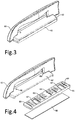
- FIG 3 shows here the handle device in assembled form, wherein grip member 62 with shoulder 65 has been slid onto base member 61.
- Grip member 62 and base member 61 are shown separately in figure 4 , wherein the base member is directed with a set of dovetail fingers 63 toward grip member 62.
- Grip member 62 in turn comprises on its side directed toward base member 61 complementary dovetail cavities 64 in which the dovetail fingers 63 of base member 61 are axially receivable and engage therein when the two members 61, 62 are slid into each other.
- the dovetail connections are uniformly distributed in a longitudinal direction over both member 61, 62 of the handle device in order to thus optimally distribute a force transmission therebetween.
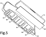
- the two members 61, 62 of the handle device are also both provided with snap means in the form of a set of resilient snap fingers 67 on the base member and a set of snap cavities 68 in grip member 62. If the two members 61, 62 are slid wholly into each other, the fingers 67 snap with their outer end behind an edge of the corresponding snap cavity 68 and thus lock the above described dovetail connection. The fingers 67 remain accessible via a set of openings 66 in the cover of the grip member so that, if desired, this snap connection can be released by freeing the outer end of the relevant finger 67 from the cavity 68 using a tool provided for this purpose, such as a pin. The two members 61, 62 of the device can thus optionally be taken apart if desired.
- Base member 61 can be connected to the flat wall 31 of the door panel in diverse ways. Base member 61 can thus be mounted by means of screws or be glued to the surface of panel 31. Application of a double-sided adhesive tape 80, of which use is made in this example, is particularly practical in this respect.
Landscapes
- Engineering & Computer Science (AREA)
- Civil Engineering (AREA)
- Structural Engineering (AREA)
- Physics & Mathematics (AREA)
- Thermal Sciences (AREA)
- Refrigerator Housings (AREA)
Applications Claiming Priority (1)
| Application Number | Priority Date | Filing Date | Title |
|---|---|---|---|
| NL2024899A NL2024899B1 (nl) | 2020-02-13 | 2020-02-13 | Koelmeubel en bedieningsinrichting daarvoor |
Publications (3)
| Publication Number | Publication Date |
|---|---|
| EP3865004A1 true EP3865004A1 (fr) | 2021-08-18 |
| EP3865004C0 EP3865004C0 (fr) | 2025-08-20 |
| EP3865004B1 EP3865004B1 (fr) | 2025-08-20 |
Family
ID=69804968
Family Applications (1)
| Application Number | Title | Priority Date | Filing Date |
|---|---|---|---|
| EP21156919.9A Active EP3865004B1 (fr) | 2020-02-13 | 2021-02-12 | Armoire refrigeree |
Country Status (2)
| Country | Link |
|---|---|
| EP (1) | EP3865004B1 (fr) |
| NL (1) | NL2024899B1 (fr) |
Citations (3)
| Publication number | Priority date | Publication date | Assignee | Title |
|---|---|---|---|---|
| US20050161461A1 (en) * | 2004-01-28 | 2005-07-28 | Samsung Electronics Co., Ltd. | Refrigerator |
| EP2345859A2 (fr) * | 2008-11-14 | 2011-07-20 | LG Electronics Inc. | Porte pour un appareil electrique et refrigerateur ayant une porte |
| US20190261785A1 (en) * | 2018-02-26 | 2019-08-29 | Anthony, Inc. | Plastic panel door |
-
2020
- 2020-02-13 NL NL2024899A patent/NL2024899B1/nl active
-
2021
- 2021-02-12 EP EP21156919.9A patent/EP3865004B1/fr active Active
Patent Citations (3)
| Publication number | Priority date | Publication date | Assignee | Title |
|---|---|---|---|---|
| US20050161461A1 (en) * | 2004-01-28 | 2005-07-28 | Samsung Electronics Co., Ltd. | Refrigerator |
| EP2345859A2 (fr) * | 2008-11-14 | 2011-07-20 | LG Electronics Inc. | Porte pour un appareil electrique et refrigerateur ayant une porte |
| US20190261785A1 (en) * | 2018-02-26 | 2019-08-29 | Anthony, Inc. | Plastic panel door |
Also Published As
| Publication number | Publication date |
|---|---|
| EP3865004C0 (fr) | 2025-08-20 |
| NL2024899B1 (nl) | 2021-09-15 |
| EP3865004B1 (fr) | 2025-08-20 |
Similar Documents
| Publication | Publication Date | Title |
|---|---|---|
| EP2613114B1 (fr) | Réfrigérateur doté d'un récipient de stockage | |
| USD367383S (en) | Storage and display cabinet | |
| JP4222733B2 (ja) | 冷却貯蔵庫 | |
| AU2223888A (en) | Switch cabinet | |
| NZ250629A (en) | Plastics kit set cabinet comprises top and bottom t-shaped panels, side panels and a pivotally mounted door | |
| US9833072B1 (en) | Rack and drawer systems and devices | |
| MXPA03008380A (es) | Estante para soportar articulos, particularmente en instalaciones refrigeradas. | |
| EP1060318A2 (fr) | Porte de vitrine | |
| KR19990072995A (ko) | 사슬형도어및부착기구를갖는캐비넷 | |
| EP3865004B1 (fr) | Armoire refrigeree | |
| USD474625S1 (en) | Storage cabinet with door | |
| US20080276423A1 (en) | Dual swing hinge structure | |
| US20180180351A1 (en) | A home appliance having drawer-type movable container with a handle | |
| WO2024192887A1 (fr) | Élément d'empilement et système d'empilement | |
| US5348383A (en) | Two way opening display case | |
| US12171334B2 (en) | Refrigerator | |
| CN216256083U (zh) | 一种收纳柜 | |
| USD534737S1 (en) | Cabinet with two doors movable in front of one another | |
| CN211795150U (zh) | 一种基于连杆原理的方便组装文件柜 | |
| CN208259397U (zh) | 一种组合式柜子 | |
| US5361927A (en) | Damped hinge mounting mechanism | |
| US10550616B2 (en) | Hinge for doors | |
| EP0392700A3 (fr) | Porte de sécurité | |
| CN215532827U (zh) | 一种设有可视窗口的储物柜 | |
| CN110450561A (zh) | 一种方便存取的学生档案盒 |
Legal Events
| Date | Code | Title | Description |
|---|---|---|---|
| PUAI | Public reference made under article 153(3) epc to a published international application that has entered the european phase |
Free format text: ORIGINAL CODE: 0009012 |
|
| STAA | Information on the status of an ep patent application or granted ep patent |
Free format text: STATUS: THE APPLICATION HAS BEEN PUBLISHED |
|
| AK | Designated contracting states |
Kind code of ref document: A1 Designated state(s): AL AT BE BG CH CY CZ DE DK EE ES FI FR GB GR HR HU IE IS IT LI LT LU LV MC MK MT NL NO PL PT RO RS SE SI SK SM TR |
|
| STAA | Information on the status of an ep patent application or granted ep patent |
Free format text: STATUS: REQUEST FOR EXAMINATION WAS MADE |
|
| 17P | Request for examination filed |
Effective date: 20220218 |
|
| RBV | Designated contracting states (corrected) |
Designated state(s): AL AT BE BG CH CY CZ DE DK EE ES FI FR GB GR HR HU IE IS IT LI LT LU LV MC MK MT NL NO PL PT RO RS SE SI SK SM TR |
|
| P01 | Opt-out of the competence of the unified patent court (upc) registered |
Effective date: 20230602 |
|
| STAA | Information on the status of an ep patent application or granted ep patent |
Free format text: STATUS: EXAMINATION IS IN PROGRESS |
|
| 17Q | First examination report despatched |
Effective date: 20230712 |
|
| GRAP | Despatch of communication of intention to grant a patent |
Free format text: ORIGINAL CODE: EPIDOSNIGR1 |
|
| STAA | Information on the status of an ep patent application or granted ep patent |
Free format text: STATUS: GRANT OF PATENT IS INTENDED |
|
| INTG | Intention to grant announced |
Effective date: 20250508 |
|
| GRAS | Grant fee paid |
Free format text: ORIGINAL CODE: EPIDOSNIGR3 |
|
| GRAA | (expected) grant |
Free format text: ORIGINAL CODE: 0009210 |
|
| STAA | Information on the status of an ep patent application or granted ep patent |
Free format text: STATUS: THE PATENT HAS BEEN GRANTED |
|
| RAP1 | Party data changed (applicant data changed or rights of an application transferred) |
Owner name: POLYPLASTIC B.V. |
|
| AK | Designated contracting states |
Kind code of ref document: B1 Designated state(s): AL AT BE BG CH CY CZ DE DK EE ES FI FR GB GR HR HU IE IS IT LI LT LU LV MC MK MT NL NO PL PT RO RS SE SI SK SM TR |
|
| REG | Reference to a national code |
Ref country code: GB Ref legal event code: FG4D |
|
| REG | Reference to a national code |
Ref country code: CH Ref legal event code: EP |
|
| REG | Reference to a national code |
Ref country code: IE Ref legal event code: FG4D |
|
| REG | Reference to a national code |
Ref country code: DE Ref legal event code: R096 Ref document number: 602021036440 Country of ref document: DE |
|
| U01 | Request for unitary effect filed |
Effective date: 20250821 |
|
| U07 | Unitary effect registered |
Designated state(s): AT BE BG DE DK EE FI FR IT LT LU LV MT NL PT RO SE SI Effective date: 20250829 |
|
| P04 | Withdrawal of opt-out of the competence of the unified patent court (upc) registered |
Free format text: CASE NUMBER: APP_472912_1/2023 Effective date: 20250829 |
|
| PG25 | Lapsed in a contracting state [announced via postgrant information from national office to epo] |
Ref country code: IS Free format text: LAPSE BECAUSE OF FAILURE TO SUBMIT A TRANSLATION OF THE DESCRIPTION OR TO PAY THE FEE WITHIN THE PRESCRIBED TIME-LIMIT Effective date: 20251220 |
|
| PG25 | Lapsed in a contracting state [announced via postgrant information from national office to epo] |
Ref country code: NO Free format text: LAPSE BECAUSE OF FAILURE TO SUBMIT A TRANSLATION OF THE DESCRIPTION OR TO PAY THE FEE WITHIN THE PRESCRIBED TIME-LIMIT Effective date: 20251120 |
|
| PG25 | Lapsed in a contracting state [announced via postgrant information from national office to epo] |
Ref country code: HR Free format text: LAPSE BECAUSE OF FAILURE TO SUBMIT A TRANSLATION OF THE DESCRIPTION OR TO PAY THE FEE WITHIN THE PRESCRIBED TIME-LIMIT Effective date: 20250820 |
|
| PG25 | Lapsed in a contracting state [announced via postgrant information from national office to epo] |
Ref country code: GR Free format text: LAPSE BECAUSE OF FAILURE TO SUBMIT A TRANSLATION OF THE DESCRIPTION OR TO PAY THE FEE WITHIN THE PRESCRIBED TIME-LIMIT Effective date: 20251121 |
|
| PG25 | Lapsed in a contracting state [announced via postgrant information from national office to epo] |
Ref country code: PL Free format text: LAPSE BECAUSE OF FAILURE TO SUBMIT A TRANSLATION OF THE DESCRIPTION OR TO PAY THE FEE WITHIN THE PRESCRIBED TIME-LIMIT Effective date: 20250820 |
|
| PG25 | Lapsed in a contracting state [announced via postgrant information from national office to epo] |
Ref country code: RS Free format text: LAPSE BECAUSE OF FAILURE TO SUBMIT A TRANSLATION OF THE DESCRIPTION OR TO PAY THE FEE WITHIN THE PRESCRIBED TIME-LIMIT Effective date: 20251120 |
|
| PG25 | Lapsed in a contracting state [announced via postgrant information from national office to epo] |
Ref country code: ES Free format text: LAPSE BECAUSE OF FAILURE TO SUBMIT A TRANSLATION OF THE DESCRIPTION OR TO PAY THE FEE WITHIN THE PRESCRIBED TIME-LIMIT Effective date: 20250820 |
|
| U20 | Renewal fee for the european patent with unitary effect paid |
Year of fee payment: 6 Effective date: 20260226 |
|
| PG25 | Lapsed in a contracting state [announced via postgrant information from national office to epo] |
Ref country code: SM Free format text: LAPSE BECAUSE OF FAILURE TO SUBMIT A TRANSLATION OF THE DESCRIPTION OR TO PAY THE FEE WITHIN THE PRESCRIBED TIME-LIMIT Effective date: 20250820 |
|
| PGFP | Annual fee paid to national office [announced via postgrant information from national office to epo] |
Ref country code: GB Payment date: 20260213 Year of fee payment: 6 |
|
| PG25 | Lapsed in a contracting state [announced via postgrant information from national office to epo] |
Ref country code: CZ Free format text: LAPSE BECAUSE OF FAILURE TO SUBMIT A TRANSLATION OF THE DESCRIPTION OR TO PAY THE FEE WITHIN THE PRESCRIBED TIME-LIMIT Effective date: 20250820 |
|
| PG25 | Lapsed in a contracting state [announced via postgrant information from national office to epo] |
Ref country code: SK Free format text: LAPSE BECAUSE OF FAILURE TO SUBMIT A TRANSLATION OF THE DESCRIPTION OR TO PAY THE FEE WITHIN THE PRESCRIBED TIME-LIMIT Effective date: 20250820 |