EP3865343A1 - Fahrzeug zur personenbeförderung, mit wenigstens einer haltestange - Google Patents
Fahrzeug zur personenbeförderung, mit wenigstens einer haltestange Download PDFInfo
- Publication number
- EP3865343A1 EP3865343A1 EP21152213.1A EP21152213A EP3865343A1 EP 3865343 A1 EP3865343 A1 EP 3865343A1 EP 21152213 A EP21152213 A EP 21152213A EP 3865343 A1 EP3865343 A1 EP 3865343A1
- Authority
- EP
- European Patent Office
- Prior art keywords
- vehicle
- holding rod
- bearing
- rod
- floating bearing
- Prior art date
- Legal status (The legal status is an assumption and is not a legal conclusion. Google has not performed a legal analysis and makes no representation as to the accuracy of the status listed.)
- Granted
Links
Images


Classifications
-
- B—PERFORMING OPERATIONS; TRANSPORTING
- B60—VEHICLES IN GENERAL
- B60N—SEATS SPECIALLY ADAPTED FOR VEHICLES; VEHICLE PASSENGER ACCOMMODATION NOT OTHERWISE PROVIDED FOR
- B60N3/00—Arrangements or adaptations of other passenger fittings, not otherwise provided for
- B60N3/02—Arrangements or adaptations of other passenger fittings, not otherwise provided for of hand grips or straps
- B60N3/026—Arrangements or adaptations of other passenger fittings, not otherwise provided for of hand grips or straps characterised by the fixing means
-
- B—PERFORMING OPERATIONS; TRANSPORTING
- B61—RAILWAYS
- B61D—BODY DETAILS OR KINDS OF RAILWAY VEHICLES
- B61D37/00—Other furniture or furnishings
Definitions
- the invention relates to a vehicle for passenger transportation according to the preamble of claim 1.
- a vehicle is provided with at least one holding rod which is connected at one end to a roof area and at its other end to a floor area of the vehicle, one of the two Ends of the support rod is connected via a floating bearing.
- the invention is based on the object of further developing a vehicle of the type mentioned in such a way that the holding rod, even if it has an inclination, is mounted in such a way that tension z. B. a vehicle shell are effectively reduced.
- the vehicle described above is characterized in that the floating bearing allows a translation of the support rod in its longitudinal direction and a rotation of the support rod about a longitudinal axis and a transverse axis of the vehicle, and the other end of the support rod is connected non-rotatably via an elastic bearing that Tilting movements of the handrail permitted.
- the floating bearing thus allows both a translation of the support rods in their longitudinal direction and a rotation of the support rods about a longitudinal axis and a transverse axis of the vehicle, while forces acting typically in the longitudinal or transverse direction of a car body of a (rail) vehicle are transmitted.
- the other end of the holding rod is connected essentially non-rotatably via an elastic bearing. This allows tilting movements and enables suitable tolerance compensation for the connection of the support rod to the vehicle shell.
- the connection of the holding rod to the vehicle shell can in particular also take place indirectly, for example via passenger seats, which in turn are connected to a base plate of the vehicle.
- the floating bearing preferably has a bolt which is axially guided in a pivot bearing. In this way, the desired degrees of freedom described above for the holding rod in the area of the floating bearing can be implemented particularly favorably.
- the elastic bearing can have a bolt which is inserted non-rotatably into a hollow-cylindrical elastomer intermediate piece.
- the relevant bolt can then tilt about a longitudinal and a transverse axis of the vehicle, so that in particular tolerances can also be compensated for.
- the floating bearing on the end of the holding rod facing the roof area of the vehicle and the elastic bearing are preferred provided at the end of the holding rod facing the floor area.
- the elastic bearing is advantageously inserted non-rotatably in a rigid receptacle, which in turn can be formed by a floor or a seat of the vehicle.
- a rigid receptacle which in turn can be formed by a floor or a seat of the vehicle.
- the end of the holding rod that interacts with the elastic bearing is thus mounted in a rotationally fixed manner, specifically preferably via the hollow-cylindrical elastomer intermediate piece and the receptacle.
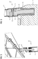
- the end Figure 1 shows the arrangement and attachment of a support rod 1 in a rail vehicle.
- the holding rod 1 is in a basic position with respect to the vehicle shell in which no forces are exerted on the holding rod 1 become.
- the upper end of the holding rod 1 is connected to a roof section 2 of a vehicle shell via a pivot bearing 3 that is rigidly connected to the holding rod 1 and a bolt 4, the upper threaded end of which is screwed into the roof section 2.
- the lower end of the bolt 4 is mounted in the pivot bearing 3 (cf. Fig. 2 ).
- the joint bearing 3 allows translational movements of the holding rod 1 in its longitudinal direction and rotational movements of the holding rod 1 about a longitudinal axis x (perpendicular to the plane of the drawing) and a transverse axis y of the vehicle. Rotations of the holding rod about the vertical axis z are only possible to a very small extent.
- the combination of the bolt 4 and the pivot bearing 3 is suitable for transmitting forces between the vehicle shell and the holding rod 1 in the transverse and longitudinal directions of the vehicle.
- the bolt 4 and the pivot bearing 3 realize a floating bearing for the upper end of the holding rod 1.
- Figure 2 also shows a cover 5 for this floating bearing with associated holders 6 for the cover 5.
- Figure 3 illustrates a lower connection area for the holding rod 1. It can be seen that a lower end of the holding rod 1 is firmly connected to a lower bearing 8 via an intermediate piece 7, specifically in the present exemplary embodiment with the aid of a connecting screw 13.
- the lower bearing 8 is designed to be elastic, ie it allows tilting movements of the holding rod 1 both about the transverse as well as about the longitudinal axis of the vehicle.
- the lower bearing 8 comprises a bolt 9 which is inserted in a rotationally fixed manner in a hollow-cylindrical elastomer intermediate piece 10.
- the elastomer intermediate piece 10 is in turn inserted non-rotatably into a rigid lower receptacle 11, which in the illustrated embodiment is a passenger seat.
- a receptacle can also be attached to a floor of the vehicle or otherwise Components connected to the floor of the vehicle may be formed.
- a cover 12 is also provided, which extends from the lower receptacle 11 to the lower end of the holding rod 1.
- FIG. 2 Also shows a transition from Fig. 2 to Fig. 5 that the holding rod has performed a translational movement essentially in the z-direction.
Landscapes
- Engineering & Computer Science (AREA)
- Mechanical Engineering (AREA)
- Transportation (AREA)
- Fittings On The Vehicle Exterior For Carrying Loads, And Devices For Holding Or Mounting Articles (AREA)
Abstract
Description
- Die Erfindung bezieht sich auf ein Fahrzeug zur Personenbeförderung nach dem Oberbegriff von Anspruch 1. Danach ist ein Fahrzeug mit wenigstens einer Haltestange vorgesehen, die mit ihrem einen Ende an einen Dachbereich und ihrem anderen Ende an einen Bodenbereich des Fahrzeugs angebunden ist, wobei eines der beiden Enden der Haltestange über ein Loslager angebunden ist.
- Insbesondere bei Schienenfahrzeugen zu Personenbeförderungszwecken ist bei der Integration von Haltestangen darauf zu achten, dass diese einen Fahrzeugrohbau, an den typischerweise die beiden Enden der jeweiligen Haltestangen angebunden sind, aber auch andere beteiligte Innenausbau-Komponenten nicht unnötig verspannen. Damit sollen negative Einflüsse auf das strukturelle und dynamische Verhalten des Fahrzeugrohbaus vermieden werden. Zu diesem Zweck ist es bekannt, ein Ende einer Haltstange mittels eines Loslagers anzubinden.
- Die Entkopplung von Haltestangen von dem Fahrzeugrohbau hinsichtlich der Übertragung von Kräften stellt explizit dann eine große Herausforderung dar, wenn die Haltestangen vertikal, d.h. zwischen einem Dach- und einem Bodenbereich des Fahrzeugs, angeordnet sind und eine Neigung aufweisen. Aus Bewegungen des Wagenkastens des Fahrzeugs können somit Verschiebungen in alle Raumrichtungen resultieren, wodurch Verformungen und/oder Verspannungen der beteiligten Komponenten auftreten können.
- Ausgehend hiervon liegt der Erfindung die Aufgabe zugrunde, ein Fahrzeug der eingangs genannten Art derart weiterzuentwickeln, dass die Haltestange, auch wenn sie eine Neigung aufweist, derart gelagert ist, dass Verspannungen z. B. eines Fahrzeugrohbaus wirksam vermindert sind.
- Diese Aufgabe wird durch ein Fahrzeug mit den Merkmalen des Anspruchs 1 gelöst. Danach zeichnet sich das eingangs beschriebene Fahrzeug dadurch aus, dass das Loslager eine Translation der Haltestange in ihrer Längsrichtung sowie eine Rotation der Haltestange um eine Längsachse und eine Querachse des Fahrzeugs gestattet, und das andere Ende der Haltestange drehfest über ein elastisches Lager angebunden ist, das Kippbewegungen der Haltestange gestattet.
- Das Loslager gestattet somit sowohl eine Translation der Haltestangen in ihrer Längsrichtung als auch an eine Rotation der Haltestangen um eine Längsachse und eine Querachse des Fahrzeugs, während typischerweise in Längs- oder Querrichtung eines Wagenkastens eines (Schienen-)Fahrzeugs wirkende Kräfte übertragen werden. Demgegenüber ist das andere Ende der Haltestange im Wesentlichen drehfest über ein elastisches Lager angebunden. Dieses gestattet Kippbewegungen und ermöglicht einen geeigneten Toleranzausgleich für die Anbindung der Haltestange am Fahrzeugrohbau. Dabei kann die Anbindung der Haltestange am Fahrzeugrohbau insbesondere auch indirekt, beispielsweise über Fahrgastsitze erfolgen, welche wiederum an eine Bodenplatte des Fahrzeugs angebunden sind.
- Das Loslager weist bevorzugt einen Bolzen auf, der in einem Gelenklager axial geführt ist. In dieser Weise lassen sich die oben beschriebenen gewünschten Freiheitsgrade für die Haltestange im Bereich des Loslagers besonders günstig realisieren.
- Das elastische Lager kann einen Bolzen aufweisen, der drehfest in eine hohlzylinderförmiges Elastomer-Zwischenstück eingesteckt ist. Der betreffende Bolzen kann sich dann um eine Längs- und eine Querachse des Fahrzeugs verkippen, so dass insbesondere auch Toleranzen ausgeglichen werden können.
- Bevorzugt ist das Loslager an dem dem Dachbereich des Fahrzeugs zugewandten Ende der Haltestange und das elastische Lager an dem dem Bodenbereich zugewandten Ende der Haltestange vorgesehen.
- Das elastische Lager ist vorteilhafterweise drehfest in eine starre Aufnahme eingesetzt, welche wiederum von einem Fußboden oder einem Sitz des Fahrzeugs gebildet sein kann. Insgesamt ist somit das mit dem elastischen Lager zusammenwirkende Ende der Haltestange drehfest gelagert, und zwar bevorzugt über das hohlzylinderförmige Elastomer-Zwischenstück und die Aufnahme.
- Ein Ausführungsbeispiel der Erfindung wird nachfolgend unter Bezugnahme auf die Zeichnung noch näher erläutert. Es zeigen:
- Figur 1
- eine Schnittansicht eines Schienenfahrzeugabschnitts, mit darin angeordneter Haltestange in ihrer Grundposition,
- Figur 2
- eine Schnittansicht eines oberen Anbindungsbereichs der Haltestange von
Fig. 1 , - Figur 3
- eine Schnittansicht eines unteren Anbindungsbereichs der Haltestange von
Figur 1 , - Figur 4
- eine Schnittansicht des Schienenfahrzeugabschnitts von Fig.l, mit darin angeordneter Haltestange in einer gegenüber der Grundposition gekippten Position,
- Figur 5
- eine Schnittansicht eines oberen Anbindungsbereichs der Haltestange von
Fig. 1 , - Figur 6
- eine Schnittansicht eines unteren Anbindungsbereichs der Haltestange von
Figur 1 . - Aus
Figur 1 geht die Anordnung und Befestigung einer Haltestange 1 in einem Schienenfahrzeug hervor. Die Haltestange 1 befindet sich in einer Grundposition gegenüber dem Fahrzeugrohbau, bei der keine Kräfte auf die Haltestange 1 ausgeübt werden. Die Haltestange 1 ist mit ihrem oberen Ende an einen Dachabschnitt 2 eines Fahrzeug-Rohbaus angebunden, und zwar über ein Gelenklager 3, das starr mit der Haltestange 1 verbunden ist, und einen Bolzen 4, dessen oberes Gewindeende in den Dachabschnitt 2 eingeschraubt ist. Das untere Ende des Bolzens 4 ist in dem Gelenklager 3 gelagert (vgl.Fig. 2 ). Das Gelenklager 3 gestattet Translationsbewegungen der Haltestange 1 in ihrer Längsrichtung sowie Drehbewegungen der Haltestange 1 um eine Längsachse x (senkrecht zur Zeichenebene der Figuren) und eine Querachse y des Fahrzeugs. Nur in sehr geringfügigem Umfang sind Rotationen der Haltestange um die Hochachse z möglich. Demgegenüber ist die Kombination aus dem Bolzen 4 und dem Gelenklager 3 dazu geeignet, in Quer- und in Längsrichtung des Fahrzeugs Kräfte zwischen dem Fahrzeug-Rohbau und der Haltestange 1 zu übertragen. - Im Ergebnis realisieren der Bolzen 4 und das Gelenklager 3 ein Loslager für das obere Ende der Haltestange 1.
-
Figur 2 zeigt zudem eine Abdeckung 5 für dieses Loslager mit zugehörigen Haltern 6 für die Abdeckung 5. -
Figur 3 veranschaulicht einen unteren Anbindungsbereich für die Haltestange 1. Es ist ersichtlich, dass ein unteres Ende der Haltestange 1 über ein Zwischenstück 7 mit einem unteren Lager 8 fest verbunden ist, und zwar im vorliegenden Ausführungsbeispiel mit Hilfe einer Verbindungsschraube 13. - Das untere Lager 8 ist elastisch ausgeführt, d.h. es erlaubt Kippbewegungen der Haltestange 1 sowohl um die Quer- als auch um die Längsachse des Fahrzeugs. Zu diesem Zweck umfasst das untere Lager 8 einen Bolzen 9, der drehfest in ein hohlzylinderförmiges Elastomer-Zwischenstück 10 eingesetzt ist. Das Elastomer-Zwischenstück 10 ist wiederum drehfest in eine starre untere Aufnahme 11 eingesetzt, bei der es sich im dargestellten Ausführungsbeispiel um einen Fahrgastsitz handelt. In anderen Ausführungen kann eine Aufnahme jedoch auch von einem Fußboden des Fahrzeugs oder auch anderweitigen, an einen Boden des Fahrzeugs angebundenen Komponenten gebildet sein.
- Zur Verkleidung des Übergangsbereich zwischen dem unteren Lager 8 und der Haltestange 1 ist zudem eine Abdeckung 12 vorgesehen, welche von der unteren Aufnahme 11 bis hin zum unteren Ende der Haltestange 1 reicht.
- Die Darstellungen der
Fig. 4 bis 6 entsprechen denjenigen derFiguren 1 bis 3 , allerdings mit dem Unterschied, dass die Haltestange 1 aufgrund von Verformungen des Fahrzeugrohbaus, die im Betrieb des Fahrzeugs durch äußere Krafteinwirkung auftreten können, um die Längsachse x des Fahrzeugs gedreht ist. Dies ist insbesondere inFig. 5 durch die deutliche Winkelstellung des Bolzens 4 zur Haltestange 1 und inFig. 6 durch eine entsprechende Winkelstellung des Bolzens 9 des unteren Lagers 8 gegenüber dem Elastomer-Zwischenstück 10 und der unteren Aufnahme 11 erkennbar. - Zudem zeigt ein Übergang von
Fig. 2 zuFig. 5 , dass die Haltestange eine Translationsbewegung im Wesentlichen in z-Richtung vollführt hat.
Claims (6)
- Fahrzeug zur Personenbeförderung, mit wenigstens einer Haltestange (1), die mit ihrem einen Ende an einen Dachabschnitt (2) und mit ihrem anderen Ende an einen Bodenbereich des Fahrzeugs angebunden ist, wobei eines der beiden Enden der Haltestange (1) über ein Loslager angebunden ist,
dadurch gekennzeichnet, dass
das Loslager eine Translation der Haltestange (1) in ihrer Längsrichtung sowie eine Rotation der Haltestange (1) um eine Längsachse (x) und eine Querachse (y) des Fahrzeugs gestattet, und das andere Ende der Haltestange (1) drehfest über ein elastisches Lager angebunden ist, das Kippbewegungen der Haltestange (1) gestattet. - Fahrzeug nach Anspruch 1,
dadurch gekennzeichnet, dass
das Loslager einen Bolzen (4) aufweist, der in einem Gelenklager (3) axial geführt ist. - Fahrzeug nach einem der Ansprüche 1oder 2,
dadurch gekennzeichnet, dass
das elastische Lager einen Bolzen (4) aufweist, der drehfest in ein hohlzylinderförmiges Elastomer-Zwischenstück (10) eingesteckt ist. - Fahrzeug nach einem der Ansprüche 1 bis 3,
dadurch gekennzeichnet, dass
das Loslager an dem dem Dachabschnitt (2) des Fahrzeugs zugewandten Ende der Haltestange (1) und das elastische Lager an dem dem Bodenbereich zugewandten Ende der Haltestange (1) vorgesehen ist. - Fahrzeug nach einem der Ansprüche 1 bis 4,
dadurch gekennzeichnet, dass
das elastische Lager drehfest in eine starre Aufnahme (11) eingesetzt ist. - Fahrzeug nach Anspruch 5,
dadurch gekennzeichnet, dass
die Aufnahme (11) von einem Fußboden oder einem Sitz des Fahrzeugs gebildet ist.
Applications Claiming Priority (1)
| Application Number | Priority Date | Filing Date | Title |
|---|---|---|---|
| DE102020201881.2A DE102020201881A1 (de) | 2020-02-14 | 2020-02-14 | Fahrzeug zur Personenbeförderung, mit wenigstens einer Haltestange |
Publications (3)
| Publication Number | Publication Date |
|---|---|
| EP3865343A1 true EP3865343A1 (de) | 2021-08-18 |
| EP3865343B1 EP3865343B1 (de) | 2025-02-26 |
| EP3865343C0 EP3865343C0 (de) | 2025-02-26 |
Family
ID=74191546
Family Applications (1)
| Application Number | Title | Priority Date | Filing Date |
|---|---|---|---|
| EP21152213.1A Active EP3865343B1 (de) | 2020-02-14 | 2021-01-19 | Fahrzeug zur personenbeförderung, mit wenigstens einer haltestange |
Country Status (3)
| Country | Link |
|---|---|
| EP (1) | EP3865343B1 (de) |
| DE (1) | DE102020201881A1 (de) |
| ES (1) | ES3029754T3 (de) |
Cited By (2)
| Publication number | Priority date | Publication date | Assignee | Title |
|---|---|---|---|---|
| WO2025223739A1 (de) * | 2024-04-26 | 2025-10-30 | Siemens Mobility GmbH | Haltestangenanordnung |
| WO2026000763A1 (zh) * | 2024-06-29 | 2026-01-02 | 比亚迪股份有限公司 | 一种扶手结构、扶手管总成以及车辆 |
Citations (3)
| Publication number | Priority date | Publication date | Assignee | Title |
|---|---|---|---|---|
| GB886568A (en) * | 1959-11-27 | 1962-01-10 | Metalastik Ltd | Improvements in or relating to stanchions for passenger transport vehicles |
| GB937692A (en) * | 1961-09-22 | 1963-09-25 | Beaton & Son Ltd G | Improved flexible coupling means for stanchions |
| DE2015107A1 (de) * | 1970-03-28 | 1971-10-28 | Daimler-Benz AO, 7000 Stuttgart-Untertürkheim | Verbindung einer Haltestange in einem Fahrzeug mit einem Beschlag |
-
2020
- 2020-02-14 DE DE102020201881.2A patent/DE102020201881A1/de not_active Ceased
-
2021
- 2021-01-19 ES ES21152213T patent/ES3029754T3/es active Active
- 2021-01-19 EP EP21152213.1A patent/EP3865343B1/de active Active
Patent Citations (3)
| Publication number | Priority date | Publication date | Assignee | Title |
|---|---|---|---|---|
| GB886568A (en) * | 1959-11-27 | 1962-01-10 | Metalastik Ltd | Improvements in or relating to stanchions for passenger transport vehicles |
| GB937692A (en) * | 1961-09-22 | 1963-09-25 | Beaton & Son Ltd G | Improved flexible coupling means for stanchions |
| DE2015107A1 (de) * | 1970-03-28 | 1971-10-28 | Daimler-Benz AO, 7000 Stuttgart-Untertürkheim | Verbindung einer Haltestange in einem Fahrzeug mit einem Beschlag |
Cited By (2)
| Publication number | Priority date | Publication date | Assignee | Title |
|---|---|---|---|---|
| WO2025223739A1 (de) * | 2024-04-26 | 2025-10-30 | Siemens Mobility GmbH | Haltestangenanordnung |
| WO2026000763A1 (zh) * | 2024-06-29 | 2026-01-02 | 比亚迪股份有限公司 | 一种扶手结构、扶手管总成以及车辆 |
Also Published As
| Publication number | Publication date |
|---|---|
| DE102020201881A1 (de) | 2021-08-19 |
| ES3029754T3 (en) | 2025-06-25 |
| EP3865343B1 (de) | 2025-02-26 |
| EP3865343C0 (de) | 2025-02-26 |
Similar Documents
| Publication | Publication Date | Title |
|---|---|---|
| DE60304643T2 (de) | Vorrichtung und System zum Filtrieren der Schwingungen einer Passagierhalterung, und mit solchem System ausgestatteter Passagierhalterung. | |
| EP2555971A1 (de) | Luftfahrzeug und befestigungsanordnung für eine fussbodenstruktur in einem luftfahrzeug | |
| EP3865343B1 (de) | Fahrzeug zur personenbeförderung, mit wenigstens einer haltestange | |
| DE102012016918A1 (de) | Fahrzeugsitz mit Bodenstellung | |
| DE102020111489A1 (de) | Fahrzeugsitz mit einer antriebsvorrichtung | |
| EP3274213A1 (de) | Adapteranordung für einen fahrzeugsitz und fahrzeugsitz | |
| DE102004055643B4 (de) | Verfahren zur Sitzverstellung und Sitz | |
| DE202008014250U1 (de) | Fahrzeugsitz | |
| DE102018210515A1 (de) | Tragstruktur für einen Fahrzeugsitz, Fahrzeugsitz und Fahrzeug | |
| EP2167362B1 (de) | Fahrzeug mit gelenkig verbundenen wagenkästen | |
| DE102020117429A1 (de) | Fahrzeugsitz und Fahrzeug mit Fahrzeugsitz | |
| DE102012214986B4 (de) | Vorrichtung zur freitragenden Befestigung eines Fahrgastsitzes und Verfahren zur Herstellung einer solchen Vorrichtung sowie Wagenkasten | |
| DE102008025230B4 (de) | Befestigungsvorrichtung für ein Flugzeuginnenausstattungsbauteil | |
| DE102023125397A1 (de) | Fahrzeugsitz für ein Fahrzeug | |
| DE69604620T2 (de) | Gelenkverbindung zwischen der Rückenlehne und dem Sitzteil eines Fahrzeugsitzes | |
| DE112023004390T5 (de) | Verstelleinrichtung, Sitz und Fahrzeug | |
| DE102022208888A1 (de) | Längsverstelleinrichtung und Fahrzeugsitz | |
| DE102019212624B3 (de) | Zusätzlich absenkbare Fahrwerksfederung | |
| CH672100A5 (de) | ||
| DE8429553U1 (de) | Kraftfahrzeug mit einem rahmen und einem aufbau | |
| DE102016005790B4 (de) | Fahrzeugsitz für ein Kraftfahrzeug | |
| DE2807007C2 (de) | Querkupplungsanordnung für ein Schienenfahrzeug mit mindestens zwei Fahrgestellen | |
| DE102022117466B4 (de) | Fahrzeugsitz, Nutzfahrzeug mit einem Fahrzeugsitz | |
| DE102019111595B4 (de) | Doppelbeschlag für einen fahrzeugsitz und fahrzeugsitz | |
| DE102018101836A1 (de) | Befestigungssystem zum Befestigen von Einbauten in einem Fahrzeug |
Legal Events
| Date | Code | Title | Description |
|---|---|---|---|
| PUAI | Public reference made under article 153(3) epc to a published international application that has entered the european phase |
Free format text: ORIGINAL CODE: 0009012 |
|
| STAA | Information on the status of an ep patent application or granted ep patent |
Free format text: STATUS: THE APPLICATION HAS BEEN PUBLISHED |
|
| AK | Designated contracting states |
Kind code of ref document: A1 Designated state(s): AL AT BE BG CH CY CZ DE DK EE ES FI FR GB GR HR HU IE IS IT LI LT LU LV MC MK MT NL NO PL PT RO RS SE SI SK SM TR |
|
| STAA | Information on the status of an ep patent application or granted ep patent |
Free format text: STATUS: REQUEST FOR EXAMINATION WAS MADE |
|
| 17P | Request for examination filed |
Effective date: 20220204 |
|
| RBV | Designated contracting states (corrected) |
Designated state(s): AL AT BE BG CH CY CZ DE DK EE ES FI FR GB GR HR HU IE IS IT LI LT LU LV MC MK MT NL NO PL PT RO RS SE SI SK SM TR |
|
| STAA | Information on the status of an ep patent application or granted ep patent |
Free format text: STATUS: EXAMINATION IS IN PROGRESS |
|
| 17Q | First examination report despatched |
Effective date: 20230803 |
|
| GRAP | Despatch of communication of intention to grant a patent |
Free format text: ORIGINAL CODE: EPIDOSNIGR1 |
|
| STAA | Information on the status of an ep patent application or granted ep patent |
Free format text: STATUS: GRANT OF PATENT IS INTENDED |
|
| INTG | Intention to grant announced |
Effective date: 20240930 |
|
| GRAS | Grant fee paid |
Free format text: ORIGINAL CODE: EPIDOSNIGR3 |
|
| GRAA | (expected) grant |
Free format text: ORIGINAL CODE: 0009210 |
|
| STAA | Information on the status of an ep patent application or granted ep patent |
Free format text: STATUS: THE PATENT HAS BEEN GRANTED |
|
| AK | Designated contracting states |
Kind code of ref document: B1 Designated state(s): AL AT BE BG CH CY CZ DE DK EE ES FI FR GB GR HR HU IE IS IT LI LT LU LV MC MK MT NL NO PL PT RO RS SE SI SK SM TR |
|
| REG | Reference to a national code |
Ref country code: GB Ref legal event code: FG4D Free format text: NOT ENGLISH |
|
| REG | Reference to a national code |
Ref country code: CH Ref legal event code: EP |
|
| REG | Reference to a national code |
Ref country code: DE Ref legal event code: R096 Ref document number: 502021006736 Country of ref document: DE |
|
| REG | Reference to a national code |
Ref country code: IE Ref legal event code: FG4D Free format text: LANGUAGE OF EP DOCUMENT: GERMAN |
|
| U01 | Request for unitary effect filed |
Effective date: 20250226 |
|
| U07 | Unitary effect registered |
Designated state(s): AT BE BG DE DK EE FI FR IT LT LU LV MT NL PT RO SE SI Effective date: 20250304 |
|
| REG | Reference to a national code |
Ref country code: ES Ref legal event code: FG2A Ref document number: 3029754 Country of ref document: ES Kind code of ref document: T3 Effective date: 20250625 |
|
| PG25 | Lapsed in a contracting state [announced via postgrant information from national office to epo] |
Ref country code: RS Free format text: LAPSE BECAUSE OF FAILURE TO SUBMIT A TRANSLATION OF THE DESCRIPTION OR TO PAY THE FEE WITHIN THE PRESCRIBED TIME-LIMIT Effective date: 20250526 |
|
| PG25 | Lapsed in a contracting state [announced via postgrant information from national office to epo] |
Ref country code: PL Free format text: LAPSE BECAUSE OF FAILURE TO SUBMIT A TRANSLATION OF THE DESCRIPTION OR TO PAY THE FEE WITHIN THE PRESCRIBED TIME-LIMIT Effective date: 20250226 |
|
| PG25 | Lapsed in a contracting state [announced via postgrant information from national office to epo] |
Ref country code: NO Free format text: LAPSE BECAUSE OF FAILURE TO SUBMIT A TRANSLATION OF THE DESCRIPTION OR TO PAY THE FEE WITHIN THE PRESCRIBED TIME-LIMIT Effective date: 20250526 Ref country code: IS Free format text: LAPSE BECAUSE OF FAILURE TO SUBMIT A TRANSLATION OF THE DESCRIPTION OR TO PAY THE FEE WITHIN THE PRESCRIBED TIME-LIMIT Effective date: 20250626 |
|
| PG25 | Lapsed in a contracting state [announced via postgrant information from national office to epo] |
Ref country code: HR Free format text: LAPSE BECAUSE OF FAILURE TO SUBMIT A TRANSLATION OF THE DESCRIPTION OR TO PAY THE FEE WITHIN THE PRESCRIBED TIME-LIMIT Effective date: 20250226 |
|
| PG25 | Lapsed in a contracting state [announced via postgrant information from national office to epo] |
Ref country code: GR Free format text: LAPSE BECAUSE OF FAILURE TO SUBMIT A TRANSLATION OF THE DESCRIPTION OR TO PAY THE FEE WITHIN THE PRESCRIBED TIME-LIMIT Effective date: 20250527 |
|
| PG25 | Lapsed in a contracting state [announced via postgrant information from national office to epo] |
Ref country code: SM Free format text: LAPSE BECAUSE OF FAILURE TO SUBMIT A TRANSLATION OF THE DESCRIPTION OR TO PAY THE FEE WITHIN THE PRESCRIBED TIME-LIMIT Effective date: 20250226 |
|
| RAP4 | Party data changed (patent owner data changed or rights of a patent transferred) |
Owner name: SIEMENS MOBILITY GMBH |
|
| U1H | Name or address of the proprietor changed after the registration of the unitary effect |
Owner name: SIEMENS MOBILITY GMBH; DE |
|
| PG25 | Lapsed in a contracting state [announced via postgrant information from national office to epo] |
Ref country code: CZ Free format text: LAPSE BECAUSE OF FAILURE TO SUBMIT A TRANSLATION OF THE DESCRIPTION OR TO PAY THE FEE WITHIN THE PRESCRIBED TIME-LIMIT Effective date: 20250226 |
|
| PG25 | Lapsed in a contracting state [announced via postgrant information from national office to epo] |
Ref country code: SK Free format text: LAPSE BECAUSE OF FAILURE TO SUBMIT A TRANSLATION OF THE DESCRIPTION OR TO PAY THE FEE WITHIN THE PRESCRIBED TIME-LIMIT Effective date: 20250226 |
|
| PLBE | No opposition filed within time limit |
Free format text: ORIGINAL CODE: 0009261 |
|
| STAA | Information on the status of an ep patent application or granted ep patent |
Free format text: STATUS: NO OPPOSITION FILED WITHIN TIME LIMIT |
|
| REG | Reference to a national code |
Ref country code: CH Ref legal event code: L10 Free format text: ST27 STATUS EVENT CODE: U-0-0-L10-L00 (AS PROVIDED BY THE NATIONAL OFFICE) Effective date: 20260107 |
|
| 26N | No opposition filed |
Effective date: 20251127 |
|
| U20 | Renewal fee for the european patent with unitary effect paid |
Year of fee payment: 6 Effective date: 20260119 |
|
| REG | Reference to a national code |
Ref country code: CH Ref legal event code: U11 Free format text: ST27 STATUS EVENT CODE: U-0-0-U10-U11 (AS PROVIDED BY THE NATIONAL OFFICE) Effective date: 20260402 |
|
| PGFP | Annual fee paid to national office [announced via postgrant information from national office to epo] |
Ref country code: GB Payment date: 20260210 Year of fee payment: 6 |