EP3865386B1 - Capteur de position et procédé de détection de position - Google Patents
Capteur de position et procédé de détection de position Download PDFInfo
- Publication number
- EP3865386B1 EP3865386B1 EP20199220.3A EP20199220A EP3865386B1 EP 3865386 B1 EP3865386 B1 EP 3865386B1 EP 20199220 A EP20199220 A EP 20199220A EP 3865386 B1 EP3865386 B1 EP 3865386B1
- Authority
- EP
- European Patent Office
- Prior art keywords
- detection value
- sensor
- magnetic sensor
- locus
- anomaly
- Prior art date
- Legal status (The legal status is an assumption and is not a legal conclusion. Google has not performed a legal analysis and makes no representation as to the accuracy of the status listed.)
- Active
Links
Images





Classifications
-
- G—PHYSICS
- G01—MEASURING; TESTING
- G01D—MEASURING NOT SPECIALLY ADAPTED FOR A SPECIFIC VARIABLE; ARRANGEMENTS FOR MEASURING TWO OR MORE VARIABLES NOT COVERED IN A SINGLE OTHER SUBCLASS; TARIFF METERING APPARATUS; MEASURING OR TESTING NOT OTHERWISE PROVIDED FOR
- G01D5/00—Mechanical means for transferring the output of a sensing member; Means for converting the output of a sensing member to another variable where the form or nature of the sensing member does not constrain the means for converting; Transducers not specially adapted for a specific variable
- G01D5/12—Mechanical means for transferring the output of a sensing member; Means for converting the output of a sensing member to another variable where the form or nature of the sensing member does not constrain the means for converting; Transducers not specially adapted for a specific variable using electric or magnetic means
- G01D5/14—Mechanical means for transferring the output of a sensing member; Means for converting the output of a sensing member to another variable where the form or nature of the sensing member does not constrain the means for converting; Transducers not specially adapted for a specific variable using electric or magnetic means influencing the magnitude of a current or voltage
- G01D5/142—Mechanical means for transferring the output of a sensing member; Means for converting the output of a sensing member to another variable where the form or nature of the sensing member does not constrain the means for converting; Transducers not specially adapted for a specific variable using electric or magnetic means influencing the magnitude of a current or voltage using Hall-effect devices
- G01D5/145—Mechanical means for transferring the output of a sensing member; Means for converting the output of a sensing member to another variable where the form or nature of the sensing member does not constrain the means for converting; Transducers not specially adapted for a specific variable using electric or magnetic means influencing the magnitude of a current or voltage using Hall-effect devices influenced by the relative movement between the Hall device and magnetic fields
-
- F—MECHANICAL ENGINEERING; LIGHTING; HEATING; WEAPONS; BLASTING
- F02—COMBUSTION ENGINES; HOT-GAS OR COMBUSTION-PRODUCT ENGINE PLANTS
- F02D—CONTROLLING COMBUSTION ENGINES
- F02D31/00—Use of speed-sensing governors to control combustion engines, not otherwise provided for
- F02D31/001—Electric control of rotation speed
- F02D31/007—Electric control of rotation speed controlling fuel supply
-
- G—PHYSICS
- G01—MEASURING; TESTING
- G01D—MEASURING NOT SPECIALLY ADAPTED FOR A SPECIFIC VARIABLE; ARRANGEMENTS FOR MEASURING TWO OR MORE VARIABLES NOT COVERED IN A SINGLE OTHER SUBCLASS; TARIFF METERING APPARATUS; MEASURING OR TESTING NOT OTHERWISE PROVIDED FOR
- G01D3/00—Indicating or recording apparatus with provision for the special purposes referred to in the subgroups
- G01D3/08—Indicating or recording apparatus with provision for the special purposes referred to in the subgroups with provision for safeguarding the apparatus, e.g. against abnormal operation, against breakdown
-
- G—PHYSICS
- G01—MEASURING; TESTING
- G01D—MEASURING NOT SPECIALLY ADAPTED FOR A SPECIFIC VARIABLE; ARRANGEMENTS FOR MEASURING TWO OR MORE VARIABLES NOT COVERED IN A SINGLE OTHER SUBCLASS; TARIFF METERING APPARATUS; MEASURING OR TESTING NOT OTHERWISE PROVIDED FOR
- G01D5/00—Mechanical means for transferring the output of a sensing member; Means for converting the output of a sensing member to another variable where the form or nature of the sensing member does not constrain the means for converting; Transducers not specially adapted for a specific variable
- G01D5/12—Mechanical means for transferring the output of a sensing member; Means for converting the output of a sensing member to another variable where the form or nature of the sensing member does not constrain the means for converting; Transducers not specially adapted for a specific variable using electric or magnetic means
- G01D5/14—Mechanical means for transferring the output of a sensing member; Means for converting the output of a sensing member to another variable where the form or nature of the sensing member does not constrain the means for converting; Transducers not specially adapted for a specific variable using electric or magnetic means influencing the magnitude of a current or voltage
-
- B—PERFORMING OPERATIONS; TRANSPORTING
- B60—VEHICLES IN GENERAL
- B60W—CONJOINT CONTROL OF VEHICLE SUB-UNITS OF DIFFERENT TYPE OR DIFFERENT FUNCTION; CONTROL SYSTEMS SPECIALLY ADAPTED FOR HYBRID VEHICLES; ROAD VEHICLE DRIVE CONTROL SYSTEMS FOR PURPOSES NOT RELATED TO THE CONTROL OF A PARTICULAR SUB-UNIT
- B60W2420/00—Indexing codes relating to the type of sensors based on the principle of their operation
- B60W2420/50—Magnetic or electromagnetic sensors
- B60W2420/503—Hall effect or magnetoresistive, i.e. active wheel speed sensors
-
- B—PERFORMING OPERATIONS; TRANSPORTING
- B62—LAND VEHICLES FOR TRAVELLING OTHERWISE THAN ON RAILS
- B62J—CYCLE SADDLES OR SEATS; AUXILIARY DEVICES OR ACCESSORIES SPECIALLY ADAPTED TO CYCLES AND NOT OTHERWISE PROVIDED FOR, e.g. ARTICLE CARRIERS OR CYCLE PROTECTORS
- B62J45/00—Electrical equipment arrangements specially adapted for use as accessories on cycles, not otherwise provided for
- B62J45/40—Sensor arrangements; Mounting thereof
- B62J45/41—Sensor arrangements; Mounting thereof characterised by the type of sensor
- B62J45/413—Rotation sensors
-
- B—PERFORMING OPERATIONS; TRANSPORTING
- B62—LAND VEHICLES FOR TRAVELLING OTHERWISE THAN ON RAILS
- B62K—CYCLES; CYCLE FRAMES; CYCLE STEERING DEVICES; RIDER-OPERATED TERMINAL CONTROLS SPECIALLY ADAPTED FOR CYCLES; CYCLE AXLE SUSPENSIONS; CYCLE SIDECARS, FORECARS, OR THE LIKE
- B62K23/00—Rider-operated controls specially adapted for cycles, i.e. means for initiating control operations, e.g. levers, grips
- B62K23/02—Rider-operated controls specially adapted for cycles, i.e. means for initiating control operations, e.g. levers, grips hand actuated
- B62K23/04—Twist grips
-
- F—MECHANICAL ENGINEERING; LIGHTING; HEATING; WEAPONS; BLASTING
- F02—COMBUSTION ENGINES; HOT-GAS OR COMBUSTION-PRODUCT ENGINE PLANTS
- F02D—CONTROLLING COMBUSTION ENGINES
- F02D11/00—Arrangements for, or adaptations to, non-automatic engine control initiation means, e.g. operator initiated
- F02D11/02—Arrangements for, or adaptations to, non-automatic engine control initiation means, e.g. operator initiated characterised by hand, foot, or like operator controlled initiation means
-
- F—MECHANICAL ENGINEERING; LIGHTING; HEATING; WEAPONS; BLASTING
- F02—COMBUSTION ENGINES; HOT-GAS OR COMBUSTION-PRODUCT ENGINE PLANTS
- F02D—CONTROLLING COMBUSTION ENGINES
- F02D2200/00—Input parameters for engine control
- F02D2200/02—Input parameters for engine control the parameters being related to the engine
- F02D2200/04—Engine intake system parameters
- F02D2200/0404—Throttle position
-
- G—PHYSICS
- G01—MEASURING; TESTING
- G01R—MEASURING ELECTRIC VARIABLES; MEASURING MAGNETIC VARIABLES
- G01R15/00—Details of measuring arrangements of the types provided for in groups G01R17/00 - G01R29/00, G01R33/00 - G01R33/26 or G01R35/00
- G01R15/14—Adaptations providing voltage or current isolation, e.g. for high-voltage or high-current networks
- G01R15/20—Adaptations providing voltage or current isolation, e.g. for high-voltage or high-current networks using galvano-magnetic devices, e.g. Hall-effect devices, i.e. measuring a magnetic field via the interaction between a current and a magnetic field, e.g. magneto resistive or Hall effect devices
-
- G—PHYSICS
- G01—MEASURING; TESTING
- G01R—MEASURING ELECTRIC VARIABLES; MEASURING MAGNETIC VARIABLES
- G01R33/00—Arrangements or instruments for measuring magnetic variables
- G01R33/02—Measuring direction or magnitude of magnetic fields or magnetic flux
- G01R33/06—Measuring direction or magnitude of magnetic fields or magnetic flux using galvano-magnetic devices
- G01R33/07—Hall effect devices
-
- G—PHYSICS
- G05—CONTROLLING; REGULATING
- G05B—CONTROL OR REGULATING SYSTEMS IN GENERAL; FUNCTIONAL ELEMENTS OF SUCH SYSTEMS; MONITORING OR TESTING ARRANGEMENTS FOR SUCH SYSTEMS OR ELEMENTS
- G05B2219/00—Program-control systems
- G05B2219/20—Pc systems
- G05B2219/25—Pc structure of the system
- G05B2219/25272—Hall sensor, switch
-
- G—PHYSICS
- G05—CONTROLLING; REGULATING
- G05B—CONTROL OR REGULATING SYSTEMS IN GENERAL; FUNCTIONAL ELEMENTS OF SUCH SYSTEMS; MONITORING OR TESTING ARRANGEMENTS FOR SUCH SYSTEMS OR ELEMENTS
- G05B2219/00—Program-control systems
- G05B2219/30—Nc systems
- G05B2219/37—Measurements
- G05B2219/37094—Hall sensor
Definitions
- the present invention relates to a position sensor and a position detection method for detecting the position of a moving body.
- a driver On a motorcycle, a driver mainly rotates a throttle grip and thereby adjusts an accelerator opening to operate an accelerator.
- An accelerator opening is detected by detection of the rotation angle of a throttle grip. Meanwhile, in recent years, an accelerator opening is often detected by detection of a magnetic flux generated by a magnet rotating together with a throttle grip by a magnetic sensor.
- DE 43 17 259 A1 discloses a rotary position sensor for detecting the position of a throttle valve in a vehicle comprises permanent magnets arranged to rotate with a shaft. Two sensors, e.g. Hall effect sensors are arranged fixed relative to the magnets such that they generate an output which varies with rotation of the shaft. The sensors are both arranged to detect the same signal. Malfunctions of the sensor system can be detected by comparison of the sensor signals with each other.
- EP 1 069 400 A1 discloses an angular position detecting apparatus using a magnetic detecting element, which can voluntary widely set an output change characteristic of the magnetic detecting element with respect to angular positions.
- EP 3 604 773 A1 discloses an accelerator position detection device that facilitates detection of a neutral position of a handlebar grip turnable in not only a positive direction but in a negative direction from the neutral position.
- US 2019/094008 A1 discloses a grip, a magnet, and a substrate.
- the grip is rotatable between positions where a throttle is fully closed and a position where the throttle is fully open with a rotating shaft as a center.
- the magnet rotates integrally with the grip.
- the substrate includes a plurality of Hall elements, and is fixed to face the magnet.
- Patent Document 1 discloses an example of an accelerator opening detection device that detects an accelerator opening by using a magnetic sensor.
- the accelerator opening detection device disclosed by Patent Document 1 includes an accelerator opening sensor including a first sensor and a second sensor that detect the rotation angle of a handle grip. Then, the accelerator opening detection device detects an angle in a forward rotation direction, an angle in a reverse rotation direction and a neutral position of the handle grip based on outputs from the first sensor and the second sensor.
- the accelerator opening detection device sets a rising start opening of an output voltage of the first sensor and a rising start opening of an output voltage of the second sensor to be different from each other, and thereby detects an angle in a forward rotation direction from the output voltage of the first sensor and detects an angle in a reverse rotation direction from the output voltage of the second sensor.
- the accelerator opening detection device disclosed by Patent Document 1 is configured to be able to detect angles in a plurality of rotation ranges of the handle grip, such as the forward rotation direction and the reverse rotation direction.
- the accelerator opening detection device disclosed by Patent Document 1 also includes a function to detect an anomaly in the sensor based on the outputs from the first sensor and the second sensor.
- the accelerator opening detection device sets initial values or slopes representing changes corresponding to the angle of the handle grip to be different between a first voltage that is the output voltage of the first sensor and a second voltage that is the output voltage of the second sensor, and the accelerator opening detection device is configured to, when the first voltage is lower than the second voltage, detect occurrence of an anomaly in the sensor.
- Patent Document 1 WO 2018/173254
- the accelerator opening detection device disclosed by Patent Document 1 mentioned above may fail to detect occurrence of an anomaly in the sensor.
- the first sensor and the second sensor are influenced by an external magnetic field simultaneously, or in a case where an anomaly occurs only in the second sensor, the first voltage does not become lower than the second voltage, and occurrence of an anomaly in the sensor cannot be detected.
- the principles of the above accelerator opening detection device are applied not only to a handle grip from which a rotation angle is detected but also to a position sensor configured to detect positions in a plurality of movement ranges of a moving body to be detected, it is also impossible to detect occurrence of an anomaly in the sensor as described above.
- an object of the present invention is to solve the abovementioned problem that it is impossible to detect occurrence of an anomaly in a position sensor that can detect positions in a plurality of movement ranges of a moving body.
- the present invention makes it possible to detect occurrence of an anomaly in a position sensor that can detect positions in a plurality of movement ranges of a moving body.
- FIG. 1 to 6 are views for describing a configuration of a position sensor
- Fig. 7 is a view for describing an operation of the position sensor
- Figs. 8 and 10 are views for describing other configurations of the position sensor.
- the position sensor in this example embodiment is a device for detecting the degree of rotation, that is, a rotation position in a rotation direction (a position) of a rotating body.
- the position sensor in this example embodiment is mounted on a throttle device 100 for operating an accelerator of a motorcycle and is for detecting the rotation angle of a throttle grip 1.
- the position sensor in this example embodiment also has a function to detect occurrence of an anomaly in the position sensor.
- the position sensor according to the present invention is not necessarily limited to being mounted on a throttle device, and may be used for detecting the rotation position of any rotating body.
- the position sensor of the present invention is not limited to being used for detecting the rotation position of a rotating body, and may be used for detecting the movement position of a moving body.
- Fig. 1 is a perspective view of the throttle device 100 in this example embodiment.
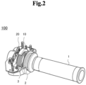
- Fig. 2 is a partially cutaway perspective view of the throttle device 100 shown in Fig. 1 .
- the throttle device 100 shown in Fig. 1 is attached onto the right side of a handle of a motorcycle.
- a grip 1 that is a rotating body is attached to a rotating shaft 2 of the throttle device 100.
- the grip 1 is rotatable about the rotating shaft 2 among a first position, a second position and a third position, which will be described later.
- the first position (a specific rotation position) refers to a position to which the grip 1 naturally returns, and is a grip position with a throttle fully closed in which a rotation angle is set to nearly 0 degree.
- the grip position is the first position, and an engine of the motorcycle is in an idle state.
- the first position is set within a predetermined range in which the rotation angle of the grip 1 is around 0 degree, for example, from -2.5 degrees to +2 degrees.
- the second position is a position where the operator who is the rider on the motorcycle has rotated the grip 1 in a frontward direction (a second position direction: one direction) from the first position to a position in which the grip 1 cannot be further turned, and is a grip position with the throttle fully open in which the rotation angle is a positive value.
- a second position direction one direction
- the rotation angle is a positive value.
- the third position is a position where the operator who is the rider on the motorcycle has rotated the grip 1 in a traveling direction (a third position direction: a reversed rotation direction from the one direction) from the first position to a position in which the grip 1 cannot be further rotated, and is a grip position where the rotation angle is a negative value, for example, the rotation angle is -10 degrees.
- a traveling direction a third position direction: a reversed rotation direction from the one direction
- the rotation angle is a negative value, for example, the rotation angle is -10 degrees.
- a return spring 3, a magnet 10 and a substrate 20 are provided inside the throttle device 100.
- the return spring 3 is connected to the grip 1, and applies a returning energizing force to the grip 1 rotating in a throttle open direction (second position direction) from the first position.
- a mechanism such as another spring that applies a returning energizing force to the grip 1 rotating from the first position in an opposite direction (third position direction) to the throttle open direction is also provided inside the throttle device 100.
- the magnet 10 is coupled with the grip 1, and rotates integrally with the grip 1. Then, the magnet 10 rotates along an outer periphery of the return spring 3.
- the magnet 10 is a segment (C) type magnet having an arc shape. Both ends in a longitudinal direction of the magnet 10 are magnetized into the N pole and the S pole.
- the substrate 20 includes a plurality of magnetic sensors, and is fixed so as to face the magnet 10.
- the magnetic sensor include a Hall element, a magneto-resistive effect element, a magnetic impedance element, and a superconductive quantum interference element.
- a Hall element is used as the magnetic sensor.
- Fig. 3 is a view schematically showing a positional relation between the magnet and the substrate in the first position of the grip 1 shown in Fig. 2 .
- Fig. 4 is a view schematically showing a positional relation between the magnet and the substrate in the second position of the grip 1 shown in Fig. 2 .
- the magnet 10 is housed in a magnet holder 4.
- the magnet holder 4 is attached to one end of the grip 1 (see Fig. 2 ) coaxially with the rotating shaft 2 of the grip 1.
- the grip 1 rotates
- the magnet holder 4 rotates in an interlocking manner in a direction shown by an arrow in Fig. 3 .
- the substrate 20 is fixedly attached in a housing (not shown) of the throttle device 100 (see Fig. 2 ). Therefore, the magnet 10 rotates along a surface of the fixed substrate 20. Moreover, two Hall ICs 21 and 22 are attached to the substrate 20.
- the first Hall IC 21 (not shown in Figs. 3 and 4 ) is provided on a magnet-10-side surface of the substrate 20, and the second Hall IC 22 is provided on an opposite surface to the magnet-10-side surface of the substrate 20.
- the two Hall ICs 21 and 22 face the near-side portion of the end portion of one magnetic pole (for example, the N pole) of the magnet 10.
- the magnet 10 has rotated from the position of Fig. 3 , and therefore, the two Hall ICs 21 and 22 face the other magnetic pole (for example, the S pole) side of the magnet 10.
- the grip 1 when the grip 1 is located in the third position in which the grip 1 is further rotated in the traveling direction from the position with the throttle fully closed, the magnet 10 has been further rotated from the position of Fig. 3 in the opposite direction to the position of Fig. 4 , so that the two Hall ICs 21 and 22 face the end portion side of the one magnetic pole (for example, the N pole) of the magnet 10.
- Hall elements are provided in the two Hall ICs 21 and 22, respectively. Therefore, the two Hall elements are fixed to the substrate 20 so as to face the magnet 10.
- the two Hall elements are provided on the front and rear surfaces of the substrate 20, respectively.
- the Hall elements are placed so that, when an external magnetic field (for example, a ferromagnetic field) acts in a state in which the grip 1 is located in the first position with the throttle fully closed, the densities of magnetic fluxes applied to the two Hall elements, respectively, have a difference.
- an external magnetic field for example, a ferromagnetic field
- the two Hall elements are placed to be mutually offset in two directions; a direction of magnetic field lines of the magnetic field and a direction intersecting the direction of the magnetic field lines.
- Offsetting the two Hall elements in the direction of the magnetic field lines of the magnetic field corresponds to making the positions of the two Hall elements different from each other on a plane of the substrate 20. Offsetting the two hall elements in the direction intersecting with the direction of the magnetic field lines corresponds to placing the two Hall elements on the front surface and the rear surface, respectively, so as to make the positions of the Hall elements different from each other by using the thickness of the substrate 20.
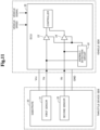
- the position sensor includes the abovementioned magnet 10 and the substrate 20 including the first sensor 21 and the second sensor 22 that are configured by two Hall ICs including the Hall elements, respectively.
- the substrate 20 is connected to an ECU (Engine Control Unit) 30 mounted on a vehicle that is the motorcycle, and is supplied with power.
- the substrate 20 includes the first sensor 21 and the second sensor 22 as mentioned above, and includes amplifiers 23 and 24 that amplify voltage values that are detected values by the first sensor 21 and the second sensor 22, respectively.
- the substrate 20 is connected to the ECU 30 via a signal line, and is configured to be able to input voltage values Va and Vb detected by the first sensor 21 and the second sensor 22 and amplified by the amplifiers 23 and 24, into the ECU 30.
- the respective amplifiers 23 and 24 are configured to amplify the detection value detected by the first sensor 21 (a first detection value) and the detection value detected by the second sensor 22 (a second detection value) so that a relation between the respective detection values is a preset relation. That is to say, the detection values detected by the first sensor 21 and the second sensor 22 are set so as to become values having a preset relation in accordance with the rotation angle of the magnet 10 by the functions of the amplifiers 23 and 24. For example, the respective detection values by the first sensor 21 and the second sensor 22 are set so as to become identical values in the case of the rotation angles of the magnet 10 being identical values.
- the detection values by the first sensor 21 and the second sensor 22 are set so as to become values on identical loci previously set in accordance with the rotation angle of the magnet 10 as indicated by reference symbols L1 and L2 in Fig. 6 by the functions of the amplifiers 23 and 24.
- the loci L1 and L2 of the detection values by the first sensor 21 and the second sensor 22 are not limited to being completely identical.
- the loci L1 and L2 may have a difference within a preset range, and may be substantially identical.
- a plurality of sections are set in a range of the rotation angle of the magnet 10, and change rates of the detection values by the first and second sensors 21 corresponding to change of the rotation angle of the magnet 10 are set so as to be different for each of the sections.
- a first section of -10 degrees to -5 degrees (a section less than D2)
- a second section of-5 degrees to +2 degrees (a section equal to or more than D2 and less than D1)
- a third section of equal to or more than +2 degrees (a section equal to or more than D1) are set as the sections of the rotation angle of the magnet 10.
- the second section is a section that includes the first position of the grip and also includes location on the third position side.
- the change rates of the detection values are 0, that is, constant values.
- the change rates are each set to a change rate a such that the detection values increase as the rotation angle increases.
- the change rates are each set to a change rate b such that the detection values increase as the rotation angle increases.
- the change rate b of the third section that is, the slope b thereof is set to be larger than the change rate a of the second section, that is, the slope a thereof.
- the substrate 20 includes an anomaly detection circuit 25 (detector) configured by an electronic circuit.
- the anomaly detection circuit 25 has a function to detect occurrence of an anomaly in the first sensor 21 or the second sensor 22 by using voltage values that are detection values detected by the first sensor 21 and the second sensor 22.
- the anomaly detection circuit 25 converts the detection values detected by the first sensor 21 and the second sensor 22 into the voltage values Va and Vb so that the detection values become amplified values in the same manner as the amplifiers 23 and 24 mounted on the substrate 20, and examines the presence/absence of change in the relation between the voltage values Va and Vb.
- the relation between the voltage values Va and Vb a relation such that both the voltage values take identical loci, that is, identical values is set.
- the anomaly detection circuit 25 checks whether the relation is satisfied or not. In a case where the voltage values Va and Vb are different values and do not satisfy the relation such that the voltage values take identical values, that is, the preset relation has changed, the anomaly detection circuit 25 detects occurrence of an anomaly in the first sensor 21 or the second sensor 22.
- An anomaly is, for example, a failure of one of the sensors or occurrence of an external magnetic field.
- the first sensor 21 and the second sensor 22 are placed with an offset, and therefore, when an external magnetic field which is different from a magnetic flux from the magnet 10 occurs, the detection values vary greatly. Consequently, occurrence of an external magnetic field can also be detected.
- the anomaly detection circuit 25 Since the loci L1 and L2 of the detection values detected by the first sensor 21 and the second sensor 22 are substantially identical, even if the voltage values Va and Vb are different values, the anomaly detection circuit 25 does not detect occurrence of an anomaly when the difference between the voltage values is within a range that can be determined to be substantially identical. That is to say, the anomaly detection circuit 25 detects occurrence of an anomaly when the voltage values Va and Vb are different values and the difference therebetween is outside a preset range.
- the anomaly detection circuit 25 controls the output of the voltage values Va and Vb detected by the first sensor 21 and the second sensor 22, depending on the presence/absence of occurrence of an anomaly. For example, when not detecting occurrence of an anomaly, the anomaly detection circuit 25 does not engage in the output of the voltage values Va and Vb to the ECU 30. As a result, the substrate 20 outputs the voltage values Va and Vb detected by the first sensor 21 and the second sensor 22 to the ECU 30, and the ECU 30 detects a throttle opening corresponding to the voltage values and performs throttle control for the detected throttle opening. That is to say, the ECU 30 functions as a sensor that detects the rotation angle of the grip 1, that is, the magnet 10.
- the voltage values Va and Vb detected by the first sensor 21 and the second sensor 22 are identical values, and therefore, the ECU 30 may use either of the voltage values, for example, the voltage value Va detected by the first sensor 21 to detect a throttle opening and perform throttle control.
- the ECU 30 performs control so that the output of the engine of the motorcycle increases as the rotation angle increases.
- the grip is located in the abovementioned first position and the voltage value is within a range of a voltage value V2 to a voltage value V3 corresponding to the rotation angle of -2.5 degrees to +2 degrees as shown in Fig. 6
- the ECU 30 performs idling control.
- the ECU 30 performs control to cancel the cruise control function.
- the voltage value detected by the first sensor 21 is V1
- the change rate b of the detection value is set to be large as compared with the change rate of the other sections. Therefore, the resolution with respect to the detected value is high, and the output of the engine can be controlled more accurately according to the rotation angle of the grip 1.
- the anomaly detection circuit 25 when detecting occurrence of an anomaly, the anomaly detection circuit 25 outputs anomaly signals to the amplifiers 23 and 24, for example.
- the amplifiers 23 and 24 set the voltage values Va and Vb detected by the first sensor 21 and the second sensor 22 to LOW level, and output to the ECU 30. Consequently, the ECU 30 executes control set in case of anomaly detection such as the throttle control being stopped.
- the anomaly detection circuit 25 may output an anomaly signal directly to the ECU 30 or another device, or may perform another process to notify the anomaly.
- the first sensor 21 and the second sensor 22 detect at all times the directions of magnetic fluxes generated by the magnet 10 rotating in conjunction with the rotation of the throttle grip 1, and output the detection values to the anomaly detection circuit 25.
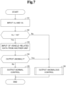
- the anomaly detection circuit 25 converts the detection values detected by the first sensor 21 and the second sensor 22 into the voltage values Va and Vb so that the detection values become amplified values in the same manner as the amplifiers 23 and 24 mounted on the substrate 20, and inputs the voltage values Va and Vb (step S1).
- the anomaly detection circuit 25 checks change in the relation between the voltage values Va and Vb. To be specific, the anomaly detection circuit 25 checks whether the relation that the voltage values Va and Vb are values on identical loci, that is, the values substantially coincide is satisfied or not (step S2). In a case where the voltage values Va and Vb are substantially identical values (Yes at step S2), the anomaly detection circuit 25 does not detect occurrence of an anomaly. In this case, the voltage values Va and Vb obtained by amplifying the detection values detected by the first sensor 21 and the second sensor 22 by the amplifiers 23 and 24 are output from the substrate 20 to the ECU 30.
- the ECU 30 receives input of vehicle-related data such as vehicle speed and a predetermined vehicle signal from another unit, (step S3), and determines based on the data whether or not the accelerator position sensor output is anomalous (Step S4).
- vehicle-related data such as vehicle speed and a predetermined vehicle signal from another unit
- Step S4 determines based on the data whether or not the accelerator position sensor output is anomalous
- the ECU 30 determines that the accelerator position sensor output is not anomalous (No at step S4)
- the ECU 30 performs output normal control (step S5).
- the ECU 30 detects a throttle opening corresponding to one of the voltage values Va and Vb output from the substrate 20, and performs throttle control for the throttle opening.
- the anomaly detection circuit 25 detects occurrence of an anomaly.
- the anomaly detection circuit 25 outputs anomaly signals to the amplifiers 23 and 24, the anomaly signals are transmitted from the amplifiers 23 and 24 to the ECU 30, and the ECU 30 performs the output anomaly control (step S6).
- the ECU 30 performs the output anomaly control set in case of detection of occurrence of an anomaly such as the throttle control being stopped.
- the loci of the detection values corresponding to the rotation angle of the magnet 10 detected by the first sensor 21 and the second sensor 22 that are magnetic sensors are set in advance, and are also set so that change rates vary in each of a plurality of sections of a range where the magnet 10 rotates. Therefore, from the detection values detected by the magnetic sensors, a position in each of the sections where the magnet 10 rotates can be detected with accuracy suitable for each of the sections. Moreover, a relation is set in advance between the detection values detected by the first sensor 21 and the second sensor 22, and it is possible, by comparing the detection values having been detected with each other and checking whether or not the relation is satisfied, to detect whether or not an anomaly has occurred in the magnetic sensors. As a result, occurrence of an anomaly can be detected in the entire rotation range of the magnet 10, that is, the grip 1.
- the change rates of the respective detection values are set to be identical in each of the abovementioned sections.
- the locus L1 of the detection value detected by the first sensor 21 is identical to that of the example of Fig. 6 described above.
- the locus L2 of the detection value detected by the second sensor 22 is set so as to have lower values as a whole than the values of the locus L1 of the first sensor 21, and a relation such that in the case of the rotation angle of the magnet 10 being identical, the difference between the detection values detected by the first sensor 21 and the second sensor is constant is set.
- the loci L1 and L2 of the detection values detected by the first sensor 21 and the second sensor 22 are not limited to being completely parallel to each other, and may be substantially parallel. That is to say, the difference between the detection values detected by the first sensor 21 and the second sensor 22 with respect to the identical rotation angle of the magnet 10 may be a difference within a preset range.
- the anomaly detection circuit 25 checks whether or not the difference of voltage values that are the detection values detected by the first sensor 21 and the second sensor 22 is a preset constant value (or value within a specific range). When not a constant value (or not within the specific range), the anomaly detection circuit 25 detects occurrence of an anomaly. Meanwhile, in the case of not detecting occurrence of an anomaly, the ECU 30 may detect the rotation angle of the magnet 10 based on the detection value detected by either one of the sensors.
- a relation as shown in Fig. 9 may be set by the functions of the amplifiers 23 and 24.
- the locus L1 of the detection value detected by the first sensor 21 is identical to that of the example of Fig. 6 described above.
- the locus L2 of the detection value detected by the second sensor 22 is set to have lower values as a whole than those of the locus L1 of the first sensor 21, and a relation such that in the case of the rotation angle of the magnet 10 being identical, the detection value detected by the second sensor is 1/2 of the detection value detected by the first sensor 21 is set.
- the loci L1 and L2 of the detection values detected by the first sensor 21 and the second sensor 22 are not limited to being set so that the detection value detected by the second sensor 22 is completely 1/2 of the detection value detected by the first sensor 21.
- the detection value detected by the second sensor 22 may be substantially 1/2 of the detection value detected by the first sensor 21.
- the anomaly detection circuit 25 checks whether or not a voltage value that is the detection value detected by the second sensor 22 is substantially 1/2 of a voltage value that is the detection value detected by the first sensor 21. When not 1/2, the anomaly detection circuit 25 detects occurrence of an anomaly. Meanwhile, when not detecting occurrence of an anomaly, the ECU 30 may detect the rotation angle of the magnet 10 based on the detection value detected by either one of the sensors.
- the loci L1 and L2 of the detection values detected by the first sensor 21 and the second sensor 22 are set so that the change rates of the detection values according to change of the rotation angle of the magnet 10 change at two change points, that is, a change point between the first section and the second section and a change point between the second section and the third section, but such a change point is not limited to two.
- the number of change points on the loci L1 and L2 may be one point, or may be three or more points.
- the example shown in Fig. 10 shows a case where the loci L1 and L2 of the detection values detected by the first sensor 21 and the second sensor 22 are almost identical and have three change points of the change rates.
- a new change point of the change rate is set in a position where the rotation angle of the magnet 10 is -2.5 degrees in the second section.
- the number of change points on the loci L1 and L2 may be one point or three or more points.
- the relation between the detection value detected by the first sensor 21 and the detection value detected by the second sensor 22 set by the functions of the amplifiers 23 and 24 is not limited to the abovementioned relations, and may be any relation.
- the anomaly detection circuit 25 compares the detection values detected by the respective sensors 21 and 22 and, when a preset relation is not satisfied, detects occurrence of an anomaly.
- the anomaly detection circuit 25 may check the relation between the detection value detected by the first sensor 21 and a preset comparison value, and detect occurrence of an anomaly based on the relation.
- the comparison value may be a value detected by another sensor that detects a value corresponding to the angle of the magnet 10, such as an encoder or a photocoupler.
- the anomaly detection circuit 25 converts the detection values detected by the first sensor 21 and the second sensor 22 into the voltage values Va and Vb that are values amplified by the amplifiers 23 and 24, and checks the presence/absence of change in the relation between the voltage values Va and Vb. Meanwhile, by using the voltage values Va and Vb amplified by the amplifiers 23 and 24, the anomaly detection circuit 25 may check the presence/absence of change in the relation between the values and detect occurrence of an anomaly.
- the configuration is not limited to the position sensor detecting a position in a rotation direction, and is also applicable to a position sensor detecting a position of a moving body moving in all directions. For example, by replacing the rotating direction of the magnet 10 with a linear direction, even when detecting the position of a moving body moving in the linear direction, it is possible to detect the moving position and detect occurrence of an anomaly.
Landscapes
- Engineering & Computer Science (AREA)
- Physics & Mathematics (AREA)
- General Physics & Mathematics (AREA)
- Chemical & Material Sciences (AREA)
- Combustion & Propulsion (AREA)
- Mechanical Engineering (AREA)
- General Engineering & Computer Science (AREA)
- Measurement Of Length, Angles, Or The Like Using Electric Or Magnetic Means (AREA)
- Control Of Throttle Valves Provided In The Intake System Or In The Exhaust System (AREA)
Claims (12)
- Un capteur de position comprenant :un aimant (10) configuré pour se déplacer avec un corps mobile ;un capteur magnétique (21) configuré pour détecter un flux magnétique généré par l'aimant (10) ;un autre capteur magnétique (22) configuré pour détecter un flux magnétique généré par l'aimant (10), l'autre capteur magnétique (22) étant différent du capteur magnétique (21) ; etun détecteur (25) configuré pour détecter une anomalie du capteur magnétique (21) sur la base d'une valeur de détection détectée par le capteur magnétique (21), dans lequel :le capteur magnétique (21) est réglé de manière à détecter la valeur de détection prenant une valeur sur un emplacement, ou "locus", prédéfini conformément à une position du corps mobile, et le locus est défini de sorte qu'un taux de changement de la valeur de détection correspondant au changement de la position du corps mobile diffère pour chaque section d'une pluralité de sections définies dans une gamme de mouvement du corps mobile ;l'autre capteur magnétique (22) est réglé de manière à détecter une deuxième valeur de détection prenant une valeur sur un deuxième locus prédéfini conformément à la position du corps en mouvement, et le deuxième locus est défini de manière à avoir une relation prédéfinie avec le locus pour chacune des sections ;la pluralité de sections comprend une première section dans laquelle aucun taux de changement n'est défini, une deuxième section dans laquelle un taux de changement est défini et une troisième section dans laquelle un taux de changement supérieur à celui de la deuxième section est défini ; etle détecteur (25) est configuré pour détecter l'anomalie du capteur magnétique sur la base d'une relation entre une première valeur de détection qui est la valeur de détection détectée par le capteur magnétique (21) et la deuxième valeur de détection détectée par l'autre capteur magnétique (22),le deuxième locus étant défini de sorte qu'un taux de changement de la deuxième valeur de détection est sensiblement identique au taux de changement de la première valeur de détection pour chacune des sections ; etle détecteur (25) étant configuré pour détecter l'anomalie du capteur magnétique (21) sur la base de la relation entre la première valeur de détection et la deuxième valeur de détection.
- Le capteur de position selon la revendication 1, dans lequel
le détecteur (25) est configuré pour détecter l'anomalie du capteur magnétique (21) lorsqu'une relation prédéfinie entre la valeur de détection et la valeur de comparaison change. - Le capteur de position selon la revendication 2, dans lequel :le deuxième locus est défini de façon à être identique ou parallèle au locus ; etle détecteur (25) est configuré pour détecter l'anomalie du capteur magnétique (21) lorsqu'une relation prédéfinie entre la première valeur de détection et la deuxième valeur de détection change.
- Le capteur de position selon l'une quelconque des revendications 1 à 3, dans lequel :le corps mobile est un corps rotatif ; etle capteur magnétique (21) est réglé pour détecter la valeur de détection en prenant la valeur sur le locus en fonction d'un angle de rotation du corps rotatif, et le locus est défini de sorte qu'un taux de changement de la valeur de détection correspondant au changement de l'angle de rotation du corps rotatif diffère pour chaque section d'une pluralité de sections définies dans une gamme de rotation du corps rotatif.
- Le capteur de position selon l'une quelconque des revendications 1 à 4, comprenant en outre un autre capteur magnétique (22) configuré pour détecter un flux magnétique généré par l'aimant (10), l'autre capteur magnétique (22) étant différent du capteur magnétique (21),l'autre capteur magnétique (22) étant réglé de manière à détecter une deuxième valeur de détection prenant une valeur sur un deuxième locus prédéfini conformément à l'angle de rotation du corps rotatif, et le deuxième locus est défini de manière à avoir une relation prédéfinie avec le locus de chacune des sections ; etle détecteur (25) étant configuré pour détecter l'anomalie du capteur magnétique sur la base d'une relation entre une première valeur de détection qui est la valeur de détection détectée par le capteur magnétique (21) et la deuxième valeur de détection détectée par l'autre capteur magnétique (22).
- Le capteur de position selon la revendication 5, dans lequel :en ce qui concerne les sections, au moins une plage d'un angle de rotation dans une direction en référence à une position de rotation spécifique du corps rotatif et une plage d'un angle de rotation dans une direction de rotation inversée par rapport à ladite une direction en référence à la position de rotation spécifique sont définies ;le locus et le deuxième locus sont définis de sorte que le taux de changement de la première valeur de détection et le taux de changement de la deuxième valeur de détection soient sensiblement identiques pour chacune des sections ; etle détecteur (25) est configuré pour détecter l'anomalie du capteur magnétique (21) sur la base de la relation entre la première valeur de détection et la deuxième valeur de détection.
- Le capteur de position selon la revendication 5 ou la revendication 6, dans lequel
le locus et le deuxième locus sont définis de manière à avoir un point de changement où le taux de changement de la première valeur de détection et le taux de changement de la deuxième valeur de détection changent pour chacune des sections. - Le capteur de position selon l'une quelconque des revendications 5 ou 6, dans lequelle deuxième locus est défini de façon à être identique ou parallèle au locus ; etle détecteur (25) est configuré pour détecter l'anomalie du capteur magnétique (21) lorsqu'une relation prédéfinie entre la première valeur de détection et la deuxième valeur de détection change.
- Le capteur de position selon l'une quelconque des revendications 1 à 8, comprenant en outre
un capteur configuré pour détecter l'angle de rotation du corps rotatif dans chacune des sections sur la base d'au moins une parmi la première valeur de détection et la deuxième valeur de détection. - Le capteur de position selon l'une quelconque des revendications 4 à 8, dans lequel
le corps rotatif est une poignée d'accélérateur d'un véhicule. - Le procédé de détection de position exécuté par un capteur de position comprenant un capteur magnétique (21), le capteur magnétique (21) détectant un flux magnétique généré par un aimant (10) se déplaçant avec un corps mobile,dans lequel le capteur magnétique (21) est réglé de manière à détecter une valeur de détection prenant une valeur sur un locus prédéfini conformément à une position du corps en mouvement, et le locus est défini de sorte qu'un taux de changement de la valeur de détection correspondant au changement de la position du corps mobile diffère pour chaque section d'une pluralité de sections définies dans une gamme de mouvement du corps mobile,le capteur de position comprenant en outre un autre capteur magnétique (22) détectant un flux magnétique généré par l'aimant (10), l'autre capteur magnétique (22) étant différent du capteur magnétique (21) ; etl'autre capteur magnétique (22) étant réglé de manière à détecter une deuxième valeur de détection prenant une valeur sur un deuxième locus prédéfini conformément à la position du corps en mouvement, et le deuxième locus est défini de manière à avoir une relation prédéfinie avec le locus pour chacune des sections,la pluralité de sections comprenant une première section dans laquelle aucun taux de changement n'est défini, une deuxième section dans laquelle un taux de changement est défini, et une troisième section dans laquelle un taux de changement supérieur à celui de la deuxième section est défini,le procédé de détection de position comprenant le fait de détecter l'anomalie du capteur magnétique sur la base d'une relation entre une première valeur de détection qui est la valeur de détection détectée par le capteur magnétique (21) et la deuxième valeur de détection détectée par l'autre capteur magnétique (22),le deuxième locus étant défini de sorte qu'un taux de changement de la deuxième valeur de détection est sensiblement identique au taux de changement de la première valeur de détection pour chacune des sections ; etle fait de détecter l'anomalie du capteur magnétique (21) sur la base de la relation entre la première valeur de détection et la deuxième valeur de détection.
- Le procédé de détection de position selon la revendication 11,dans lequel le deuxième locus est défini de sorte qu'un taux de changement de la deuxième valeur de détection est sensiblement identique au taux de changement de la première valeur de détection pour chacune des sections,le procédé de détection de position comprenant le fait de détecter l'anomalie du capteur magnétique (21) sur la base de la relation entre la première valeur de détection et la deuxième valeur de détection,dans lequel, de préférence,le deuxième locus est défini de façon à être identique ou parallèle au locus, et de préférencele procédé de détection de position comprend le fait de détecter l'anomalie du capteur magnétique (21) lorsqu'une relation prédéfinie entre la première valeur de détection et la deuxième valeur de détection change.
Applications Claiming Priority (1)
| Application Number | Priority Date | Filing Date | Title |
|---|---|---|---|
| JP2020022978A JP7495792B2 (ja) | 2020-02-14 | 2020-02-14 | ポジションセンサ及びポジション検出方法 |
Publications (2)
| Publication Number | Publication Date |
|---|---|
| EP3865386A1 EP3865386A1 (fr) | 2021-08-18 |
| EP3865386B1 true EP3865386B1 (fr) | 2023-11-08 |
Family
ID=72709074
Family Applications (1)
| Application Number | Title | Priority Date | Filing Date |
|---|---|---|---|
| EP20199220.3A Active EP3865386B1 (fr) | 2020-02-14 | 2020-09-30 | Capteur de position et procédé de détection de position |
Country Status (3)
| Country | Link |
|---|---|
| US (1) | US11313289B2 (fr) |
| EP (1) | EP3865386B1 (fr) |
| JP (1) | JP7495792B2 (fr) |
Families Citing this family (2)
| Publication number | Priority date | Publication date | Assignee | Title |
|---|---|---|---|---|
| US20230026992A1 (en) * | 2019-12-10 | 2023-01-26 | Hirschmann Automotive Gmbh | Throttle with integrated switch block |
| CN115326803A (zh) * | 2022-08-29 | 2022-11-11 | 中山凯旋真空科技股份有限公司 | 转架位置异常的检测方法与检测装置 |
Family Cites Families (7)
| Publication number | Priority date | Publication date | Assignee | Title |
|---|---|---|---|---|
| JP3206204B2 (ja) * | 1992-05-22 | 2001-09-10 | 株式会社デンソー | スロットルポジションセンサ |
| JP4378814B2 (ja) | 1999-07-16 | 2009-12-09 | 株式会社日本自動車部品総合研究所 | 回転角検出装置 |
| JP5712576B2 (ja) | 2010-11-29 | 2015-05-07 | トヨタ自動車株式会社 | 車両の制御装置および車両の制御方法 |
| JP5472761B2 (ja) * | 2012-02-17 | 2014-04-16 | 株式会社デンソー | 位置検出装置 |
| DE102017202833A1 (de) * | 2017-02-22 | 2018-08-23 | Zf Friedrichshafen Ag | Vorrichtung und Verfahren zum Bestimmen einer Position eines Betätigungselements für ein Getriebe eines Fahrzeugs und System zum Bewirken von Schaltvorgängen eines Getriebes eines Fahrzeugs |
| CN110446841B (zh) | 2017-03-24 | 2022-02-18 | 本田技研工业株式会社 | 加速器开度检测装置 |
| JP6899297B2 (ja) | 2017-09-22 | 2021-07-07 | 東洋電装株式会社 | スロットル装置 |
-
2020
- 2020-02-14 JP JP2020022978A patent/JP7495792B2/ja active Active
- 2020-09-22 US US17/027,755 patent/US11313289B2/en active Active
- 2020-09-30 EP EP20199220.3A patent/EP3865386B1/fr active Active
Also Published As
| Publication number | Publication date |
|---|---|
| US11313289B2 (en) | 2022-04-26 |
| US20210254565A1 (en) | 2021-08-19 |
| JP7495792B2 (ja) | 2024-06-05 |
| JP2021127725A (ja) | 2021-09-02 |
| EP3865386A1 (fr) | 2021-08-18 |
Similar Documents
| Publication | Publication Date | Title |
|---|---|---|
| EP3865386B1 (fr) | Capteur de position et procédé de détection de position | |
| EP1647436B1 (fr) | Detecteur de position pour un véhicule à deux roues | |
| US10900769B2 (en) | Throttle device | |
| KR19990037040A (ko) | 회전수 검출용 센서의 배치구조 | |
| KR20060073960A (ko) | 조향각 센서 | |
| CN113532249B (zh) | 用于转向柱的绝对位置非接触式倾斜传感器 | |
| JP2005194925A (ja) | 車両のスロットル装置 | |
| JP2004340873A (ja) | 回転角度検出装置及び回転制御装置 | |
| EP3650324B1 (fr) | Système de commande de véhicule | |
| EP3835190B1 (fr) | Capteur de position et procédé de détection de position | |
| US6701237B2 (en) | Vehicle speed diagnostic algorithm for four-wheel steering systems | |
| JP7500314B2 (ja) | ポジションセンサ及びポジション検出方法 | |
| JP2008216129A (ja) | トルク検出装置 | |
| JPH06234366A (ja) | ハンドル操舵角検出装置 | |
| US11372439B2 (en) | Pedal apparatus for vehicle | |
| EP3939873A1 (fr) | Capteur de position d'accélérateur | |
| EP3748304B1 (fr) | Capteur de position doté d'une fonction de réveil | |
| EP1783460A2 (fr) | Détecteur d'angle | |
| US12203784B2 (en) | Steering angle sensing device and torque angle sensor module having the same | |
| US20030028302A1 (en) | Rear steering sensor diagnostic algorithm for four-wheel steering systems | |
| KR100384441B1 (ko) | 자동차용 가속 및 클러치 페달의 변위 측정 장치 | |
| KR20200102006A (ko) | 조향 제어 시스템 및 그 제어 방법 | |
| JP2003232691A (ja) | トルク検出機構 | |
| JPH01153384A (ja) | 農作業車 |
Legal Events
| Date | Code | Title | Description |
|---|---|---|---|
| PUAI | Public reference made under article 153(3) epc to a published international application that has entered the european phase |
Free format text: ORIGINAL CODE: 0009012 |
|
| STAA | Information on the status of an ep patent application or granted ep patent |
Free format text: STATUS: THE APPLICATION HAS BEEN PUBLISHED |
|
| AK | Designated contracting states |
Kind code of ref document: A1 Designated state(s): AL AT BE BG CH CY CZ DE DK EE ES FI FR GB GR HR HU IE IS IT LI LT LU LV MC MK MT NL NO PL PT RO RS SE SI SK SM TR |
|
| STAA | Information on the status of an ep patent application or granted ep patent |
Free format text: STATUS: REQUEST FOR EXAMINATION WAS MADE |
|
| 17P | Request for examination filed |
Effective date: 20211012 |
|
| RBV | Designated contracting states (corrected) |
Designated state(s): AL AT BE BG CH CY CZ DE DK EE ES FI FR GB GR HR HU IE IS IT LI LT LU LV MC MK MT NL NO PL PT RO RS SE SI SK SM TR |
|
| STAA | Information on the status of an ep patent application or granted ep patent |
Free format text: STATUS: EXAMINATION IS IN PROGRESS |
|
| 17Q | First examination report despatched |
Effective date: 20220810 |
|
| GRAP | Despatch of communication of intention to grant a patent |
Free format text: ORIGINAL CODE: EPIDOSNIGR1 |
|
| STAA | Information on the status of an ep patent application or granted ep patent |
Free format text: STATUS: GRANT OF PATENT IS INTENDED |
|
| INTG | Intention to grant announced |
Effective date: 20230508 |
|
| GRAS | Grant fee paid |
Free format text: ORIGINAL CODE: EPIDOSNIGR3 |
|
| GRAA | (expected) grant |
Free format text: ORIGINAL CODE: 0009210 |
|
| STAA | Information on the status of an ep patent application or granted ep patent |
Free format text: STATUS: THE PATENT HAS BEEN GRANTED |
|
| AK | Designated contracting states |
Kind code of ref document: B1 Designated state(s): AL AT BE BG CH CY CZ DE DK EE ES FI FR GB GR HR HU IE IS IT LI LT LU LV MC MK MT NL NO PL PT RO RS SE SI SK SM TR |
|
| REG | Reference to a national code |
Ref country code: GB Ref legal event code: FG4D |
|
| REG | Reference to a national code |
Ref country code: CH Ref legal event code: EP |
|
| REG | Reference to a national code |
Ref country code: DE Ref legal event code: R096 Ref document number: 602020020625 Country of ref document: DE |
|
| REG | Reference to a national code |
Ref country code: IE Ref legal event code: FG4D |
|
| REG | Reference to a national code |
Ref country code: LT Ref legal event code: MG9D |
|
| P01 | Opt-out of the competence of the unified patent court (upc) registered |
Effective date: 20240130 |
|
| REG | Reference to a national code |
Ref country code: NL Ref legal event code: MP Effective date: 20231108 |
|
| PG25 | Lapsed in a contracting state [announced via postgrant information from national office to epo] |
Ref country code: GR Free format text: LAPSE BECAUSE OF FAILURE TO SUBMIT A TRANSLATION OF THE DESCRIPTION OR TO PAY THE FEE WITHIN THE PRESCRIBED TIME-LIMIT Effective date: 20240209 |
|
| PG25 | Lapsed in a contracting state [announced via postgrant information from national office to epo] |
Ref country code: IS Free format text: LAPSE BECAUSE OF FAILURE TO SUBMIT A TRANSLATION OF THE DESCRIPTION OR TO PAY THE FEE WITHIN THE PRESCRIBED TIME-LIMIT Effective date: 20240308 |
|
| PG25 | Lapsed in a contracting state [announced via postgrant information from national office to epo] |
Ref country code: LT Free format text: LAPSE BECAUSE OF FAILURE TO SUBMIT A TRANSLATION OF THE DESCRIPTION OR TO PAY THE FEE WITHIN THE PRESCRIBED TIME-LIMIT Effective date: 20231108 |
|
| REG | Reference to a national code |
Ref country code: AT Ref legal event code: MK05 Ref document number: 1629396 Country of ref document: AT Kind code of ref document: T Effective date: 20231108 |
|
| PG25 | Lapsed in a contracting state [announced via postgrant information from national office to epo] |
Ref country code: NL Free format text: LAPSE BECAUSE OF FAILURE TO SUBMIT A TRANSLATION OF THE DESCRIPTION OR TO PAY THE FEE WITHIN THE PRESCRIBED TIME-LIMIT Effective date: 20231108 |
|
| PG25 | Lapsed in a contracting state [announced via postgrant information from national office to epo] |
Ref country code: AT Free format text: LAPSE BECAUSE OF FAILURE TO SUBMIT A TRANSLATION OF THE DESCRIPTION OR TO PAY THE FEE WITHIN THE PRESCRIBED TIME-LIMIT Effective date: 20231108 |
|
| PG25 | Lapsed in a contracting state [announced via postgrant information from national office to epo] |
Ref country code: ES Free format text: LAPSE BECAUSE OF FAILURE TO SUBMIT A TRANSLATION OF THE DESCRIPTION OR TO PAY THE FEE WITHIN THE PRESCRIBED TIME-LIMIT Effective date: 20231108 |
|
| PG25 | Lapsed in a contracting state [announced via postgrant information from national office to epo] |
Ref country code: NL Free format text: LAPSE BECAUSE OF FAILURE TO SUBMIT A TRANSLATION OF THE DESCRIPTION OR TO PAY THE FEE WITHIN THE PRESCRIBED TIME-LIMIT Effective date: 20231108 Ref country code: LT Free format text: LAPSE BECAUSE OF FAILURE TO SUBMIT A TRANSLATION OF THE DESCRIPTION OR TO PAY THE FEE WITHIN THE PRESCRIBED TIME-LIMIT Effective date: 20231108 Ref country code: IS Free format text: LAPSE BECAUSE OF FAILURE TO SUBMIT A TRANSLATION OF THE DESCRIPTION OR TO PAY THE FEE WITHIN THE PRESCRIBED TIME-LIMIT Effective date: 20240308 Ref country code: GR Free format text: LAPSE BECAUSE OF FAILURE TO SUBMIT A TRANSLATION OF THE DESCRIPTION OR TO PAY THE FEE WITHIN THE PRESCRIBED TIME-LIMIT Effective date: 20240209 Ref country code: ES Free format text: LAPSE BECAUSE OF FAILURE TO SUBMIT A TRANSLATION OF THE DESCRIPTION OR TO PAY THE FEE WITHIN THE PRESCRIBED TIME-LIMIT Effective date: 20231108 Ref country code: BG Free format text: LAPSE BECAUSE OF FAILURE TO SUBMIT A TRANSLATION OF THE DESCRIPTION OR TO PAY THE FEE WITHIN THE PRESCRIBED TIME-LIMIT Effective date: 20240208 Ref country code: AT Free format text: LAPSE BECAUSE OF FAILURE TO SUBMIT A TRANSLATION OF THE DESCRIPTION OR TO PAY THE FEE WITHIN THE PRESCRIBED TIME-LIMIT Effective date: 20231108 Ref country code: PT Free format text: LAPSE BECAUSE OF FAILURE TO SUBMIT A TRANSLATION OF THE DESCRIPTION OR TO PAY THE FEE WITHIN THE PRESCRIBED TIME-LIMIT Effective date: 20240308 |
|
| PG25 | Lapsed in a contracting state [announced via postgrant information from national office to epo] |
Ref country code: SE Free format text: LAPSE BECAUSE OF FAILURE TO SUBMIT A TRANSLATION OF THE DESCRIPTION OR TO PAY THE FEE WITHIN THE PRESCRIBED TIME-LIMIT Effective date: 20231108 Ref country code: RS Free format text: LAPSE BECAUSE OF FAILURE TO SUBMIT A TRANSLATION OF THE DESCRIPTION OR TO PAY THE FEE WITHIN THE PRESCRIBED TIME-LIMIT Effective date: 20231108 Ref country code: PL Free format text: LAPSE BECAUSE OF FAILURE TO SUBMIT A TRANSLATION OF THE DESCRIPTION OR TO PAY THE FEE WITHIN THE PRESCRIBED TIME-LIMIT Effective date: 20231108 Ref country code: NO Free format text: LAPSE BECAUSE OF FAILURE TO SUBMIT A TRANSLATION OF THE DESCRIPTION OR TO PAY THE FEE WITHIN THE PRESCRIBED TIME-LIMIT Effective date: 20240208 Ref country code: LV Free format text: LAPSE BECAUSE OF FAILURE TO SUBMIT A TRANSLATION OF THE DESCRIPTION OR TO PAY THE FEE WITHIN THE PRESCRIBED TIME-LIMIT Effective date: 20231108 Ref country code: HR Free format text: LAPSE BECAUSE OF FAILURE TO SUBMIT A TRANSLATION OF THE DESCRIPTION OR TO PAY THE FEE WITHIN THE PRESCRIBED TIME-LIMIT Effective date: 20231108 |
|
| PG25 | Lapsed in a contracting state [announced via postgrant information from national office to epo] |
Ref country code: DK Free format text: LAPSE BECAUSE OF FAILURE TO SUBMIT A TRANSLATION OF THE DESCRIPTION OR TO PAY THE FEE WITHIN THE PRESCRIBED TIME-LIMIT Effective date: 20231108 |
|
| PG25 | Lapsed in a contracting state [announced via postgrant information from national office to epo] |
Ref country code: CZ Free format text: LAPSE BECAUSE OF FAILURE TO SUBMIT A TRANSLATION OF THE DESCRIPTION OR TO PAY THE FEE WITHIN THE PRESCRIBED TIME-LIMIT Effective date: 20231108 |
|
| PG25 | Lapsed in a contracting state [announced via postgrant information from national office to epo] |
Ref country code: SK Free format text: LAPSE BECAUSE OF FAILURE TO SUBMIT A TRANSLATION OF THE DESCRIPTION OR TO PAY THE FEE WITHIN THE PRESCRIBED TIME-LIMIT Effective date: 20231108 |
|
| PG25 | Lapsed in a contracting state [announced via postgrant information from national office to epo] |
Ref country code: SM Free format text: LAPSE BECAUSE OF FAILURE TO SUBMIT A TRANSLATION OF THE DESCRIPTION OR TO PAY THE FEE WITHIN THE PRESCRIBED TIME-LIMIT Effective date: 20231108 Ref country code: SK Free format text: LAPSE BECAUSE OF FAILURE TO SUBMIT A TRANSLATION OF THE DESCRIPTION OR TO PAY THE FEE WITHIN THE PRESCRIBED TIME-LIMIT Effective date: 20231108 Ref country code: RO Free format text: LAPSE BECAUSE OF FAILURE TO SUBMIT A TRANSLATION OF THE DESCRIPTION OR TO PAY THE FEE WITHIN THE PRESCRIBED TIME-LIMIT Effective date: 20231108 Ref country code: EE Free format text: LAPSE BECAUSE OF FAILURE TO SUBMIT A TRANSLATION OF THE DESCRIPTION OR TO PAY THE FEE WITHIN THE PRESCRIBED TIME-LIMIT Effective date: 20231108 Ref country code: DK Free format text: LAPSE BECAUSE OF FAILURE TO SUBMIT A TRANSLATION OF THE DESCRIPTION OR TO PAY THE FEE WITHIN THE PRESCRIBED TIME-LIMIT Effective date: 20231108 Ref country code: CZ Free format text: LAPSE BECAUSE OF FAILURE TO SUBMIT A TRANSLATION OF THE DESCRIPTION OR TO PAY THE FEE WITHIN THE PRESCRIBED TIME-LIMIT Effective date: 20231108 |
|
| REG | Reference to a national code |
Ref country code: DE Ref legal event code: R097 Ref document number: 602020020625 Country of ref document: DE |
|
| PLBE | No opposition filed within time limit |
Free format text: ORIGINAL CODE: 0009261 |
|
| STAA | Information on the status of an ep patent application or granted ep patent |
Free format text: STATUS: NO OPPOSITION FILED WITHIN TIME LIMIT |
|
| 26N | No opposition filed |
Effective date: 20240809 |
|
| PG25 | Lapsed in a contracting state [announced via postgrant information from national office to epo] |
Ref country code: SI Free format text: LAPSE BECAUSE OF FAILURE TO SUBMIT A TRANSLATION OF THE DESCRIPTION OR TO PAY THE FEE WITHIN THE PRESCRIBED TIME-LIMIT Effective date: 20231108 |
|
| PG25 | Lapsed in a contracting state [announced via postgrant information from national office to epo] |
Ref country code: SI Free format text: LAPSE BECAUSE OF FAILURE TO SUBMIT A TRANSLATION OF THE DESCRIPTION OR TO PAY THE FEE WITHIN THE PRESCRIBED TIME-LIMIT Effective date: 20231108 |
|
| PG25 | Lapsed in a contracting state [announced via postgrant information from national office to epo] |
Ref country code: MC Free format text: LAPSE BECAUSE OF FAILURE TO SUBMIT A TRANSLATION OF THE DESCRIPTION OR TO PAY THE FEE WITHIN THE PRESCRIBED TIME-LIMIT Effective date: 20231108 |
|
| REG | Reference to a national code |
Ref country code: CH Ref legal event code: PL |
|
| PG25 | Lapsed in a contracting state [announced via postgrant information from national office to epo] |
Ref country code: LU Free format text: LAPSE BECAUSE OF NON-PAYMENT OF DUE FEES Effective date: 20240930 |
|
| GBPC | Gb: european patent ceased through non-payment of renewal fee |
Effective date: 20240930 |
|
| PG25 | Lapsed in a contracting state [announced via postgrant information from national office to epo] |
Ref country code: GB Free format text: LAPSE BECAUSE OF NON-PAYMENT OF DUE FEES Effective date: 20240930 |
|
| REG | Reference to a national code |
Ref country code: BE Ref legal event code: MM Effective date: 20240930 |
|
| PG25 | Lapsed in a contracting state [announced via postgrant information from national office to epo] |
Ref country code: BE Free format text: LAPSE BECAUSE OF NON-PAYMENT OF DUE FEES Effective date: 20240930 |
|
| PG25 | Lapsed in a contracting state [announced via postgrant information from national office to epo] |
Ref country code: FR Free format text: LAPSE BECAUSE OF NON-PAYMENT OF DUE FEES Effective date: 20240930 |
|
| PG25 | Lapsed in a contracting state [announced via postgrant information from national office to epo] |
Ref country code: CH Free format text: LAPSE BECAUSE OF NON-PAYMENT OF DUE FEES Effective date: 20240930 |
|
| PG25 | Lapsed in a contracting state [announced via postgrant information from national office to epo] |
Ref country code: IE Free format text: LAPSE BECAUSE OF NON-PAYMENT OF DUE FEES Effective date: 20240930 |
|
| PG25 | Lapsed in a contracting state [announced via postgrant information from national office to epo] |
Ref country code: FI Free format text: LAPSE BECAUSE OF FAILURE TO SUBMIT A TRANSLATION OF THE DESCRIPTION OR TO PAY THE FEE WITHIN THE PRESCRIBED TIME-LIMIT Effective date: 20231108 |
|
| PGFP | Annual fee paid to national office [announced via postgrant information from national office to epo] |
Ref country code: DE Payment date: 20250919 Year of fee payment: 6 |
|
| PGFP | Annual fee paid to national office [announced via postgrant information from national office to epo] |
Ref country code: IT Payment date: 20250923 Year of fee payment: 6 |
|
| PG25 | Lapsed in a contracting state [announced via postgrant information from national office to epo] |
Ref country code: CY Free format text: LAPSE BECAUSE OF FAILURE TO SUBMIT A TRANSLATION OF THE DESCRIPTION OR TO PAY THE FEE WITHIN THE PRESCRIBED TIME-LIMIT; INVALID AB INITIO Effective date: 20200930 |
|
| PG25 | Lapsed in a contracting state [announced via postgrant information from national office to epo] |
Ref country code: HU Free format text: LAPSE BECAUSE OF FAILURE TO SUBMIT A TRANSLATION OF THE DESCRIPTION OR TO PAY THE FEE WITHIN THE PRESCRIBED TIME-LIMIT; INVALID AB INITIO Effective date: 20200930 |