EP3865462A1 - Appareil et procédé de fabrication d'une préforme de verre poreux pour fibre optique - Google Patents
Appareil et procédé de fabrication d'une préforme de verre poreux pour fibre optique Download PDFInfo
- Publication number
- EP3865462A1 EP3865462A1 EP21159623.4A EP21159623A EP3865462A1 EP 3865462 A1 EP3865462 A1 EP 3865462A1 EP 21159623 A EP21159623 A EP 21159623A EP 3865462 A1 EP3865462 A1 EP 3865462A1
- Authority
- EP
- European Patent Office
- Prior art keywords
- raw material
- burner
- gas
- manufacturing
- optical fiber
- Prior art date
- Legal status (The legal status is an assumption and is not a legal conclusion. Google has not performed a legal analysis and makes no representation as to the accuracy of the status listed.)
- Withdrawn
Links
Images


Classifications
-
- C—CHEMISTRY; METALLURGY
- C03—GLASS; MINERAL OR SLAG WOOL
- C03B—MANUFACTURE, SHAPING, OR SUPPLEMENTARY PROCESSES
- C03B37/00—Manufacture or treatment of flakes, fibres, or filaments from softened glass, minerals, or slags
- C03B37/01—Manufacture of glass fibres or filaments
- C03B37/012—Manufacture of preforms for drawing fibres or filaments
- C03B37/014—Manufacture of preforms for drawing fibres or filaments made entirely or partially by chemical means, e.g. vapour phase deposition of bulk porous glass either by outside vapour deposition [OVD], or by outside vapour phase oxidation [OVPO] or by vapour axial deposition [VAD]
- C03B37/01413—Reactant delivery systems
- C03B37/0142—Reactant deposition burners
-
- C—CHEMISTRY; METALLURGY
- C03—GLASS; MINERAL OR SLAG WOOL
- C03B—MANUFACTURE, SHAPING, OR SUPPLEMENTARY PROCESSES
- C03B37/00—Manufacture or treatment of flakes, fibres, or filaments from softened glass, minerals, or slags
- C03B37/01—Manufacture of glass fibres or filaments
- C03B37/012—Manufacture of preforms for drawing fibres or filaments
- C03B37/014—Manufacture of preforms for drawing fibres or filaments made entirely or partially by chemical means, e.g. vapour phase deposition of bulk porous glass either by outside vapour deposition [OVD], or by outside vapour phase oxidation [OVPO] or by vapour axial deposition [VAD]
-
- C—CHEMISTRY; METALLURGY
- C03—GLASS; MINERAL OR SLAG WOOL
- C03B—MANUFACTURE, SHAPING, OR SUPPLEMENTARY PROCESSES
- C03B37/00—Manufacture or treatment of flakes, fibres, or filaments from softened glass, minerals, or slags
- C03B37/01—Manufacture of glass fibres or filaments
- C03B37/012—Manufacture of preforms for drawing fibres or filaments
- C03B37/014—Manufacture of preforms for drawing fibres or filaments made entirely or partially by chemical means, e.g. vapour phase deposition of bulk porous glass either by outside vapour deposition [OVD], or by outside vapour phase oxidation [OVPO] or by vapour axial deposition [VAD]
- C03B37/01413—Reactant delivery systems
-
- C—CHEMISTRY; METALLURGY
- C03—GLASS; MINERAL OR SLAG WOOL
- C03B—MANUFACTURE, SHAPING, OR SUPPLEMENTARY PROCESSES
- C03B37/00—Manufacture or treatment of flakes, fibres, or filaments from softened glass, minerals, or slags
- C03B37/01—Manufacture of glass fibres or filaments
- C03B37/012—Manufacture of preforms for drawing fibres or filaments
- C03B37/014—Manufacture of preforms for drawing fibres or filaments made entirely or partially by chemical means, e.g. vapour phase deposition of bulk porous glass either by outside vapour deposition [OVD], or by outside vapour phase oxidation [OVPO] or by vapour axial deposition [VAD]
- C03B37/01413—Reactant delivery systems
- C03B37/0142—Reactant deposition burners
- C03B37/01426—Plasma deposition burners or torches
-
- C—CHEMISTRY; METALLURGY
- C03—GLASS; MINERAL OR SLAG WOOL
- C03B—MANUFACTURE, SHAPING, OR SUPPLEMENTARY PROCESSES
- C03B2207/00—Glass deposition burners
- C03B2207/30—For glass precursor of non-standard type, e.g. solid SiH3F
- C03B2207/32—Non-halide
-
- C—CHEMISTRY; METALLURGY
- C03—GLASS; MINERAL OR SLAG WOOL
- C03B—MANUFACTURE, SHAPING, OR SUPPLEMENTARY PROCESSES
- C03B2207/00—Glass deposition burners
- C03B2207/30—For glass precursor of non-standard type, e.g. solid SiH3F
- C03B2207/34—Liquid, e.g. mist or aerosol
-
- C—CHEMISTRY; METALLURGY
- C03—GLASS; MINERAL OR SLAG WOOL
- C03B—MANUFACTURE, SHAPING, OR SUPPLEMENTARY PROCESSES
- C03B2207/00—Glass deposition burners
- C03B2207/42—Assembly details; Material or dimensions of burner; Manifolds or supports
-
- C—CHEMISTRY; METALLURGY
- C03—GLASS; MINERAL OR SLAG WOOL
- C03B—MANUFACTURE, SHAPING, OR SUPPLEMENTARY PROCESSES
- C03B2207/00—Glass deposition burners
- C03B2207/80—Feeding the burner or the burner-heated deposition site
- C03B2207/81—Constructional details of the feed line, e.g. heating, insulation, material, manifolds, filters
-
- C—CHEMISTRY; METALLURGY
- C03—GLASS; MINERAL OR SLAG WOOL
- C03B—MANUFACTURE, SHAPING, OR SUPPLEMENTARY PROCESSES
- C03B2207/00—Glass deposition burners
- C03B2207/80—Feeding the burner or the burner-heated deposition site
- C03B2207/85—Feeding the burner or the burner-heated deposition site with vapour generated from liquid glass precursors, e.g. directly by heating the liquid
Definitions
- the present invention relates to a manufacturing apparatus and a manufacturing method of a porous glass preform for optical fiber, including depositing a cladding portion on a starting core preform using an outside deposition technique (OVD).
- ODD outside deposition technique
- An optical fiber preform is manufactured by depositing SiO 2 microparticles using OVD or the like on the outside of a core preform, which is manufactured using VAD or the like, and then sintering the resulting member, for example.
- SiCl 4 silicon tetrachloride
- SiO 2 microparticles are generated due to the flame hydrolysis reaction of the SiCl 4 , based on Formula 1 shown below.
- Formula 1 SiCl 4 + 2H 2 O ⁇ SiO 2 + 4HCl
- Hydrochloric acid is formed as a by-product of this reaction, and care must be taken concerning the manufacturing apparatus materials and exhaust temperature management, since this hydrochloric acid is corrosive to metals when mixed with water. Furthermore, when equipment for performing a recover processing of the hydrochloric acid from the exhaust is provided, this results in a cost increase.
- Silicon tetrachloride (SiCl 4 ) is widely used as the silicon compound raw material, but sometimes a halogen-free organic silicon compound that does not contain Cl (chlorine) in the molecules is used as the starting material for the SiO 2 microparticles.
- This is exemplified by octamethylcyclotetrasiloxane (OMCTS), which is an organic silicon compound having a high purity and capable of being used on an industrial scale.
- SiO 2 microparticles are generated due to the flame hydrolysis reaction of the OMCTS, based on Formula 2 shown below.
- Formula 2 [SiO(CH 3 ) 2 ] 4 + 16O 2 ⁇ 4SiO 2 + 8CO 2 + 12H 2 O
- the organic silicon compound raw material represented by OMCTS
- OMCTS When the organic silicon compound raw material, represented by OMCTS, is supplied to the burner in a liquid state, the OMCTS is vaporized and combusted irregularly by the burner, and therefore the ejection amount of the SiO 2 microparticles becomes unstable, and the flame temperature changes to cause instability in the deposition amount of the SiO 2 microparticles and the density of the deposition body.
- the manufacturing method of a porous glass preform for optical fiber solves the above problem, and is a manufacturing method of a porous glass preform for optical fiber by depositing glass microparticles on a starting member, comprising supplying a vaporizer with organic silicon compound raw material in a liquid state and a carrier gas; in the vaporizer, mixing together and vaporizing the organic silicon compound raw material in a liquid state and the carrier gas to convert the organic silicon compound raw material and the carrier gas into a raw material mixed gas; supplying a burner with the raw material mixed gas and a combustible gas, combusting the raw material mixed gas and the combustible gas in the burner, and ejecting SiO 2 microparticles generated by the combustion from the burner; and depositing the SiO 2 microparticles ejected from the burner by repeatedly moving the vaporizer and the burner together, in a synchronized manner, parallel to the starting member in a longitudinal direction thereof.
- the organic silicon compound raw material is octamethylcyclotetrasiloxane (OMCTS) with a purity greater than or equal to 99% by mass.
- OCTS octamethylcyclotetrasiloxane
- An inert gas such as nitrogen, argon, or helium may be used as the carrier gas in the raw material mixed gas, and oxygen may also be mixed into the raw material mixed gas supplied to the burner. Oxygen or a mixed gas including oxygen and an inert gas may be used as the carrier gas.
- a manufacturing apparatus for manufacturing a porous glass preform for optical fiber is a manufacturing apparatus for manufacturing a porous glass preform, comprising a burner that deposits SiO 2 microparticles on a starting member while moving parallel thereto along a longitudinal direction of the starting member; a vaporizer that converts organic silicon compound raw material from a liquid state into a gaseous state, and supplies the converted gas to the burner; and a raw material liquid pipe that supplies the organic silicon compound raw material to the vaporizer, wherein the vaporizer and the burner are arranged in a manner to be movable together. It is preferable that the raw material liquid pipe is mobile in a manner to move following the burner.
- the burner and the vaporizer which vaporizes the organic silicon compound raw material, is a synchronized and integrated manner, the raw material is stably supplied to the burner in a gaseous state, and the SiO 2 microparticle ejection amount and flame temperature are stabilized. Furthermore, it is possible to achieve extremely beneficial effects such as being able to give the raw material gas pipe leading from the vaporizer to the burner a constant length that is unrelated to the region in which the burner moves, being able to shorten the raw material gas pipe relative to the length of the starting member in the longitudinal direction and making it easy to uniformly heat the raw material gas pipe.
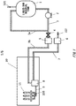
- Fig. 1 shows an example of a supply flow for supplying raw material and the like to a porous glass preform manufacturing apparatus according to the present invention.
- An organic silicon compound (raw material) 101 in a liquid state is fed from a liquid raw material tank 1.
- the method for feeding the raw material liquid 101 from the liquid raw material tank 1 may be using a liquid feeding pump 2, gas pumping, or the like, for example.
- a case is shown where the liquid feeding pump 2 is used.
- a raw material liquid pipe 3 is separated into a circulation pipe 3a that returns to the liquid raw material tank 1 and a raw material liquid supply pipe 3b that goes toward a porous glass preform manufacturing apparatus 10 via a valve 4.
- a liquid mass flow controller 5 that precisely controls the flow rate of the raw material liquid 101 is provided on the raw material liquid supply pipe 3b side.
- the raw material liquid pipe 3 preferably heats the raw material liquid 101 to a point that does not cause coagulation.
- a vaporizer 8 that vaporizes the raw material liquid 101 is arranged inside the porous glass preform manufacturing apparatus 10.
- the vaporizer 8 is also supplied with a carrier gas 102, the raw material liquid 101 is mixed with the carrier gas 102 in the vaporizer 8, and the resulting gas is supplied to a burner 11 through a raw material gas pipe 9 as a raw material gas 103.
- a gas mass flow controller 6 is provided on the carrier gas pipe 7.
- the raw material liquid 101 is provided while the liquid mass flow controller 5 changes the supply flow rate thereof from 10 g/min to 100 g/min, according to the deposition state.
- the carrier gas 102 can be an inert gas such as nitrogen, argon, or helium, or may be oxygen or a mixed gas including oxygen and an inert gas.
- the carrier gas 102 may undergo preheating according to the supply flow rate, in order to efficiently vaporize the raw material liquid 101 with the vaporizer 8.
- the carrier gas 102 By using an inert gas such as nitrogen, argon, or helium as the carrier gas 102, it is possible to safely transport the raw material. On the other hand, it is undesirable to significantly increase the ratio of the inert gas, since it is unrelated to the reaction. If an inert gas such as nitrogen is used as the carrier gas 102, the flow rate of the carrier gas 102 is preferably restricted to being less than or equal to 30 SLM.
- oxygen or a mixed gas of oxygen and inert gas is used as the carrier gas 102, complete combustion is encouraged by pre-mixing the raw material in the vaporizer.
- the supply amount of the oxygen is preferably an amount that does not cause flashback.
- the raw material liquid 101 is mixed with the carrier gas 102 in the vaporizer 8 and vaporized.
- the temperature inside the vaporizer 8 is preferably set from 150°C to 250°C.
- the raw material gas 103 including the vaporized raw material gas and the carrier gas is supplied to the burner 11 through the raw material gas pipe 9.
- the raw material gas pipe 9 is preferably heated to a temperature that is greater than a liquefaction temperature of the raw material gas, which is calculated from the partial pressure, in order to prevent reliquefaction of the raw material gas.
- the liquefaction temperature of OMCTS is 175°C when the partial pressure is 1.00 atm and is 134°C when the partial pressure is 0.30 atm.
- the heating of the raw material gas pipe 9 can be achieved using an electric heater, for example.
- the carrier gas such as oxygen is mixed with the raw material gas in the vaporizer 8, and the resulting gas is supplied to the burner 11 in a pre-mixed state. If the combustion reaction of the raw material is insufficient, a gel of impurities, impurity microparticles, or the like stick to the burner 11, carbon sticks to the soot, and defects occur in the soot. Therefore, by using oxygen as the carrier gas 102, pre-mixing the raw material and the oxygen, and supplying the resulting gas to the burner 11, it is possible to increase the reactivity of the raw material. In this way, oxygen may be used as the carrier gas 102 and this oxygen may be mixed with the raw material in the vaporizer 8, or inert gas such as nitrogen may be used as the carrier gas 102 and mixed with the raw material downstream from the vaporizer 8.
- Fig. 2 shows an example of a supply flow around the vaporizer according to the present embodiment, and shows a case where an inert gas such as nitrogen is used as the carrier gas 102, oxygen 104 is mixed with the raw material gas downstream from the vaporizer 8, and the resulting gas is supplied to the burner 11.
- an inert gas such as nitrogen
- the oxygen 104 is mixed with the raw material gas downstream from the vaporizer 8, through an oxygen pipe 13.
- the oxygen is preferably supplied in a preheated state at a temperature greater than or equal to the liquefaction temperature of the raw material gas calculated from the partial pressure, in order to prevent reliquefaction of the raw material.
- the heating of the oxygen 104 can be achieved using a small-scale heat exchanger 14 or the like.
- the carrier gas 102 may be preheated using a small-scale heat exchanger 12 or the like, according to the supply flow rate of the carrier gas 102.
- the supply flow rate of the oxygen 104 preferably has a molar ratio (standard state) for the oxygen 104 / raw material liquid 101 that is less than or equal to 8.
- a multi-nozzle burner in which a plurality of nozzles are arranged a multi-tube burner in which nozzles are arranged concentrically, or the like can be used as the burner 11.
- the gas supplied to the burner 11 is exemplified by, in addition to the raw material gas pre-mixed with the carrier gas 102 or the like, seal gas, combustible gas for combustion, oxygen gas for combustion, and the like. Hydrogen, methane, ethane, propane, or the like, for example, can be used as the combustible gas for combustion.
- Octamethylcyclotetrasiloxane hexamethyldisiloxane, hexamethylcyclotrisiloxane, decamethylcyclopentasiloxane, dodecamethylcyclohexasiloxane, trimethoxymethylsilane, tetramethoxysilane, or the like can be used as the organic silicon compound raw material.
- the boiling points of these materials are less than or equal to 300°C, and a pipe made of resin such as PTFE can be used as the pipe for the vaporized raw material gas.
- OMCTS hexamethylcyclotrisiloxane
- decamethylcyclopentasiloxane which is a pentameric cyclic siloxane
- the heating temperature of the raw material gas pipe only needs to match the boiling point of the OMCTS, and temperature management of the pipe becomes easier. Furthermore, the occurrence of polymerization products due to the reaction of the highly reactive hexamethylcyclotrisiloxane proceeding is prevented, and there is no need to excessively increase the heating temperature of the raw material gas pipe in order to match the high boiling point of the decamethylcyclopentasiloxane.
- An inert gas such as nitrogen, argon, or helium, oxygen, or a mixed gas containing oxygen and inert gas can be used as the seal gas.
- the seal gas may be provided heated, in order to prevent reliquefaction of the raw material gas.
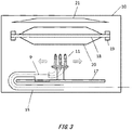
- Fig. 3 is a schematic view of the porous glass preform manufacturing apparatus used in the present invention.
- the burner 11 is moved parallel to a guide mechanism 17 using a traverse motor, not shown in the drawings.
- a starting core preform 18 is attached to a rotating mechanism 19, and rotates in a certain direction. While the burner 11 repeats the parallel motion along the longitudinal direction of the starting core preform 18, the SiO 2 microparticles generated by the raw material gas are ejected from the burner 11, and these microparticles are attached to the starting core preform 18 to form a soot deposition body 20.
- the unattached SiO 2 microparticles that did not attach to the soot deposition body 20 are expelled outside the system via an exhaust hood 21.
- the exhaust hood 21 may have localized exhaust structures or an overall exhaust structure.
- each gas pipe that supplies the raw material gas and the like to the burner 11 moves in a manner to follow the burner 11 that repeats the parallel movement.
- each pipe supplying gas to the burner 11 is preferably mobile, and by storing each gas pipe inside a mobile cable protection material 15 such as Cableveyor (Registered Trademark of TSUBAKIMOTO CHAIN CO.) or a flexible tube, for example, the gas pipes can follow the movement of the burner 11 and can move without experiencing a large amount of stress.
- the mobile cable protection material 15 is made from a flexible cylindrical member, and stores each gas cable therein.
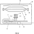
- the raw material gas pipe 9 extending from the vaporizer 8 to the burner 11 needs to be lengthened according to the length of the starting core preform 18 in the longitudinal direction and the pipe length of the raw material gas pipe 9 needs to be 2 to 3 times the movement distance of the burner in one direction, as shown in Fig. 4 .
- the length of the starting core preform 18 is 3000 mm
- the travel distance of the burner in one direction must be 3000 mm
- the pipe length of the raw material gas pipe 9 must be from 6000 mm to 9000 mm.
- the raw material gas pipe 9 In order for the raw material gas pipe 9 to prevent reliquefaction of the raw material gas, the raw material gas pipe 9 is preferably heated, using an electric heater or the like, to a temperature greater than or equal to the liquefaction temperature of the raw material gas calculated from the partial pressure. However, it is easy for temperature unevenness to occur in the pipe according to the distance from the electric heater, and it is difficult to control the temperature of the pipe to be uniform. If the vaporizer 8 is arranged secured to the front portion of the mobile cable protection material 15, the length of the raw material gas pipe 9 is increased, and therefore there are cases where the raw material component or impurity component is overheated locally to create polymers in the pipe and is condensed and liquefied at localized low-temperature portions.
- the vaporizer 8 that vaporizes the organic silicon compound in a liquid state is arranged at the rear portion of the mobile cable protection material 15, i.e. near the burner 11, and is arranged to be movable along with the burner 11 that moves due to the guide mechanism 17.
- the raw material gas pipe 9 can be set to have a certain length that is unrelated to the length of the starting core preform 18 in the longitudinal direction, and it is possible to significantly shorten the raw material gas pipe 9 leading from the vaporizer 8 to the burner 11 and to shorten the heating region of the electric heater for preventing the reliquefaction of the raw material gas.
- By making the pipe as short as possible it is possible to easily manage the temperature of the pipe and to prevent coagulation of the raw material and generation of polymers within the pipe.
- the heater is prone to breaking due to fatigue, and when a heat transfer medium is used, the pipe for the heat transfer medium is easily damaged due to fatigue. Therefore, when heating the raw material gas pipe 9, it is preferable to arrange the heating means such that excessive tensile stress and bending stress is not applied thereto, and the raw material gas pipe itself is preferably not mobile.
- the present subject-matter includes, inter alia, the following aspects:
Landscapes
- Chemical & Material Sciences (AREA)
- Engineering & Computer Science (AREA)
- Geochemistry & Mineralogy (AREA)
- Life Sciences & Earth Sciences (AREA)
- General Chemical & Material Sciences (AREA)
- General Life Sciences & Earth Sciences (AREA)
- Chemical Kinetics & Catalysis (AREA)
- Manufacturing & Machinery (AREA)
- Materials Engineering (AREA)
- Organic Chemistry (AREA)
- Physics & Mathematics (AREA)
- Plasma & Fusion (AREA)
- Manufacture, Treatment Of Glass Fibers (AREA)
- Glass Melting And Manufacturing (AREA)
Applications Claiming Priority (2)
| Application Number | Priority Date | Filing Date | Title |
|---|---|---|---|
| JP2018070632A JP6793676B2 (ja) | 2018-04-02 | 2018-04-02 | 光ファイバ用多孔質ガラス母材の製造装置および製造方法 |
| EP19166406.9A EP3549921B1 (fr) | 2018-04-02 | 2019-03-29 | Appareil et procédé de fabrication d'une préforme de verre poreux pour fibre optique |
Related Parent Applications (2)
| Application Number | Title | Priority Date | Filing Date |
|---|---|---|---|
| EP19166406.9A Division-Into EP3549921B1 (fr) | 2018-04-02 | 2019-03-29 | Appareil et procédé de fabrication d'une préforme de verre poreux pour fibre optique |
| EP19166406.9A Division EP3549921B1 (fr) | 2018-04-02 | 2019-03-29 | Appareil et procédé de fabrication d'une préforme de verre poreux pour fibre optique |
Publications (1)
| Publication Number | Publication Date |
|---|---|
| EP3865462A1 true EP3865462A1 (fr) | 2021-08-18 |
Family
ID=66041352
Family Applications (2)
| Application Number | Title | Priority Date | Filing Date |
|---|---|---|---|
| EP19166406.9A Active EP3549921B1 (fr) | 2018-04-02 | 2019-03-29 | Appareil et procédé de fabrication d'une préforme de verre poreux pour fibre optique |
| EP21159623.4A Withdrawn EP3865462A1 (fr) | 2018-04-02 | 2019-03-29 | Appareil et procédé de fabrication d'une préforme de verre poreux pour fibre optique |
Family Applications Before (1)
| Application Number | Title | Priority Date | Filing Date |
|---|---|---|---|
| EP19166406.9A Active EP3549921B1 (fr) | 2018-04-02 | 2019-03-29 | Appareil et procédé de fabrication d'une préforme de verre poreux pour fibre optique |
Country Status (4)
| Country | Link |
|---|---|
| US (2) | US11155488B2 (fr) |
| EP (2) | EP3549921B1 (fr) |
| JP (1) | JP6793676B2 (fr) |
| CN (1) | CN110342807A (fr) |
Families Citing this family (12)
| Publication number | Priority date | Publication date | Assignee | Title |
|---|---|---|---|---|
| JP7276335B2 (ja) * | 2018-06-15 | 2023-05-18 | 住友電気工業株式会社 | ガラス微粒子堆積体の製造方法 |
| JP7463967B2 (ja) * | 2018-12-04 | 2024-04-09 | 住友電気工業株式会社 | ガラス微粒子堆積体の製造装置及び製造方法 |
| JP7171639B2 (ja) * | 2020-03-13 | 2022-11-15 | 信越化学工業株式会社 | 光ファイバ用多孔質ガラス母材の製造方法 |
| JP7449842B2 (ja) * | 2020-11-02 | 2024-03-14 | 信越化学工業株式会社 | 多孔質ガラス母材の製造方法及び製造装置 |
| JP7428632B2 (ja) | 2020-12-14 | 2024-02-06 | 信越化学工業株式会社 | 多孔質ガラス母材の製造方法及び製造装置 |
| EP4015466A1 (fr) * | 2020-12-16 | 2022-06-22 | Heraeus Quarzglas GmbH & Co. KG | Procédé de fabrication de silice vitreuse synthétique |
| EP4015468A1 (fr) | 2020-12-16 | 2022-06-22 | Heraeus Quarzglas GmbH & Co. KG | Procédé de fabrication de silice vitreuse synthétique |
| EP4015467A1 (fr) * | 2020-12-16 | 2022-06-22 | Heraeus Quarzglas GmbH & Co. KG | Procédé de fabrication de silice vitreuse synthétique |
| JP7508390B2 (ja) * | 2021-02-26 | 2024-07-01 | 古河電気工業株式会社 | 光ファイバ母材の製造装置及び製造方法 |
| JP2023141265A (ja) * | 2022-03-23 | 2023-10-05 | 住友電気工業株式会社 | ガラス加工装置 |
| CN118206272A (zh) | 2022-12-15 | 2024-06-18 | 信越化学工业株式会社 | 多孔玻璃基材制造系统和用于制造玻璃基材的方法 |
| CN117985934B (zh) * | 2023-12-21 | 2026-03-10 | 华能(泰安)光电科技有限公司 | 一种光纤预制棒制备包层沉积装置 |
Citations (4)
| Publication number | Priority date | Publication date | Assignee | Title |
|---|---|---|---|---|
| JPS57188424A (en) * | 1981-05-15 | 1982-11-19 | Nippon Telegr & Teleph Corp <Ntt> | Manufacture of base material for glass fiber |
| JP2000159532A (ja) * | 1998-11-19 | 2000-06-13 | Furukawa Electric Co Ltd:The | 光ファイバ用多孔質ガラス母材の製造装置 |
| US20050155390A1 (en) * | 2004-01-14 | 2005-07-21 | Fujikura Ltd | Apparatus for manufacturing porous glass preform for optical fiber |
| US20140349830A1 (en) * | 2011-12-15 | 2014-11-27 | Heraeus Quarzglas Gmbh & Co. Kg | Method for producing synthetic quartz glass and quartz glass for use as cladding material of an optical fiber |
Family Cites Families (28)
| Publication number | Priority date | Publication date | Assignee | Title |
|---|---|---|---|---|
| US4314837A (en) | 1979-03-01 | 1982-02-09 | Corning Glass Works | Reactant delivery system method |
| JPS63134531A (ja) * | 1986-11-21 | 1988-06-07 | Furukawa Electric Co Ltd:The | ガラス微粒子合成装置 |
| JPS63285131A (ja) * | 1987-05-16 | 1988-11-22 | Fujikura Ltd | 光ファイバ母材の製造装置 |
| JPH02217330A (ja) * | 1989-02-17 | 1990-08-30 | Fujikura Ltd | 四塩化ケイ素原料ガスの供給方法および供給装置 |
| US6312656B1 (en) * | 1995-12-19 | 2001-11-06 | Corning Incorporated | Method for forming silica by combustion of liquid reactants using oxygen |
| ID24873A (id) * | 1997-07-08 | 2000-08-31 | Corning Inc | Persediaan-umpan germanium klorida dan siloksan untuk membentu kaca silika dan metoda pembuatannya |
| JP3794664B2 (ja) | 1998-07-29 | 2006-07-05 | 信越化学工業株式会社 | 合成石英ガラス部材及びその製造方法、並びにエキシマレーザ用光学部品 |
| US8516855B2 (en) * | 2001-04-27 | 2013-08-27 | Prysmian Cavi E Sistemi Energia S.R.L. | Method for producing an optical fiber preform |
| JP2003073131A (ja) * | 2001-06-19 | 2003-03-12 | Sumitomo Electric Ind Ltd | ガラス微粒子堆積体の製造方法 |
| JP3968451B2 (ja) * | 2002-07-08 | 2007-08-29 | 昭和電線ケーブルシステム株式会社 | 光ファイバ用母材の製造方法およびその製造装置 |
| JP2004161555A (ja) * | 2002-11-14 | 2004-06-10 | Sumitomo Electric Ind Ltd | ガラス形成ガスの供給方法、ガラス微粒子堆積体の製造方法及びそれぞれの装置 |
| KR100521957B1 (ko) * | 2003-07-11 | 2005-10-14 | 엘에스전선 주식회사 | 광섬유 제조를 위한 외부 기상 증착 장치 및 이를 이용한광섬유 모재 제조방법 |
| CN101287683A (zh) * | 2005-09-05 | 2008-10-15 | 斯德莱特光学技术有限公司 | 具有大尺寸烟炱多孔体的光纤预制件及其制备方法 |
| CN101292117A (zh) * | 2005-10-19 | 2008-10-22 | 冈安谦治 | 使用小型气化装置的燃烧装置 |
| KR100727362B1 (ko) * | 2007-01-05 | 2007-06-13 | 주식회사 코닥트 | 소음과 분진을 저감시킨 케이블 베어 |
| JP5399798B2 (ja) * | 2008-07-18 | 2014-01-29 | 信越化学工業株式会社 | 光ファイバ用母材の製造方法および光ファイバ用母材の製造装置 |
| DE102009010497A1 (de) * | 2008-12-19 | 2010-08-05 | J-Fiber Gmbh | Mehrdüsiger rohrförmiger Plasma-Abscheidebrenner zur Herstellung von Vorformen als Halbzeuge für optische Fasern |
| JP5793834B2 (ja) * | 2010-07-15 | 2015-10-14 | 住友電気工業株式会社 | ガラス微粒子堆積体製造方法およびガラス体製造方法 |
| US9630872B2 (en) * | 2011-09-29 | 2017-04-25 | Sumitomo Electric Industries, Ltd. | Method for manufacturing glass-fine-particle-deposited body and method for manufacturing glass base material |
| DE102011119339A1 (de) * | 2011-11-25 | 2013-05-29 | Heraeus Quarzglas Gmbh & Co. Kg | Zerstäubungsverfahren zur Herstellung von synthetischem Quarzglas |
| DE102011119374A1 (de) * | 2011-11-25 | 2013-05-29 | Heraeus Quarzglas Gmbh & Co. Kg | Verfahren zur Herstellung von synthetischem Quarzglas |
| JP5935882B2 (ja) * | 2012-12-28 | 2016-06-15 | 住友電気工業株式会社 | ガラス微粒子堆積体の製造方法およびガラス母材の製造方法 |
| DE102013209673B3 (de) * | 2013-05-24 | 2014-05-22 | Heraeus Quarzglas Gmbh & Co. Kg | Verfahren und Verdampfer zur Herstellung von synthetischem Quarzglas |
| CN103755135B (zh) * | 2013-12-25 | 2016-08-17 | 中天科技精密材料有限公司 | 一种光纤预制棒外包层高效制备方法及其设备 |
| JP6284275B2 (ja) * | 2014-12-22 | 2018-02-28 | 信越化学工業株式会社 | 光ファイバ用母材の製造装置 |
| JP2017036172A (ja) * | 2015-08-07 | 2017-02-16 | 株式会社フジクラ | 光ファイバ母材の製造方法 |
| US11577982B2 (en) * | 2015-10-07 | 2023-02-14 | Corning Incorporated | Method to prevent cracks in optical fiber preforms |
| CN106082633B (zh) * | 2016-08-22 | 2019-07-23 | 长飞光纤光缆股份有限公司 | 一种用于沉积光纤预制棒的燃烧器与沉积方法 |
-
2018
- 2018-04-02 JP JP2018070632A patent/JP6793676B2/ja active Active
-
2019
- 2019-03-20 CN CN201910213190.8A patent/CN110342807A/zh active Pending
- 2019-03-29 EP EP19166406.9A patent/EP3549921B1/fr active Active
- 2019-03-29 EP EP21159623.4A patent/EP3865462A1/fr not_active Withdrawn
- 2019-04-01 US US16/371,118 patent/US11155488B2/en active Active
-
2021
- 2021-09-01 US US17/463,566 patent/US20210395131A1/en not_active Abandoned
Patent Citations (4)
| Publication number | Priority date | Publication date | Assignee | Title |
|---|---|---|---|---|
| JPS57188424A (en) * | 1981-05-15 | 1982-11-19 | Nippon Telegr & Teleph Corp <Ntt> | Manufacture of base material for glass fiber |
| JP2000159532A (ja) * | 1998-11-19 | 2000-06-13 | Furukawa Electric Co Ltd:The | 光ファイバ用多孔質ガラス母材の製造装置 |
| US20050155390A1 (en) * | 2004-01-14 | 2005-07-21 | Fujikura Ltd | Apparatus for manufacturing porous glass preform for optical fiber |
| US20140349830A1 (en) * | 2011-12-15 | 2014-11-27 | Heraeus Quarzglas Gmbh & Co. Kg | Method for producing synthetic quartz glass and quartz glass for use as cladding material of an optical fiber |
Also Published As
| Publication number | Publication date |
|---|---|
| US11155488B2 (en) | 2021-10-26 |
| US20210395131A1 (en) | 2021-12-23 |
| JP2019182668A (ja) | 2019-10-24 |
| EP3549921B1 (fr) | 2021-05-05 |
| JP6793676B2 (ja) | 2020-12-02 |
| CN110342807A (zh) | 2019-10-18 |
| EP3549921A1 (fr) | 2019-10-09 |
| US20190300419A1 (en) | 2019-10-03 |
Similar Documents
| Publication | Publication Date | Title |
|---|---|---|
| US11155488B2 (en) | Apparatus and method for manufacturing porous glass preform for optical fiber | |
| KR100473827B1 (ko) | 액체반응물의연소에의해용융실리카를제조하는방법및장치 | |
| AU741475B2 (en) | Method and apparatus for forming silica by combustion of liquidreactants using a heater | |
| EP3450407B1 (fr) | Procédé de fabrication d'une matrice de verre | |
| US10167543B2 (en) | Method for manufacturing optical fiber preform | |
| CN104163569A (zh) | 玻璃微粒堆叠体的制造方法及玻璃微粒堆叠体制造用燃烧器 | |
| JP2020200225A (ja) | 光ファイバ用多孔質ガラス母材の製造装置および製造方法 | |
| JP7463967B2 (ja) | ガラス微粒子堆積体の製造装置及び製造方法 | |
| US12509387B2 (en) | Apparatus and method for producing porous glass preform | |
| US12371364B2 (en) | Porous glass base material manufacturing apparatus, method for manufacturing porous glass base material, and method for manufacturing glass base material for optical fiber | |
| JPH10203842A (ja) | 光ファイバ母材製造方法 | |
| JP7194301B2 (ja) | 光ファイバ用多孔質ガラス母材の製造方法 | |
| JP7449842B2 (ja) | 多孔質ガラス母材の製造方法及び製造装置 | |
| KR20210116270A (ko) | 광파이버용 다공질 유리 모재의 제조 방법 |
Legal Events
| Date | Code | Title | Description |
|---|---|---|---|
| PUAI | Public reference made under article 153(3) epc to a published international application that has entered the european phase |
Free format text: ORIGINAL CODE: 0009012 |
|
| STAA | Information on the status of an ep patent application or granted ep patent |
Free format text: STATUS: THE APPLICATION HAS BEEN PUBLISHED |
|
| AC | Divisional application: reference to earlier application |
Ref document number: 3549921 Country of ref document: EP Kind code of ref document: P |
|
| AK | Designated contracting states |
Kind code of ref document: A1 Designated state(s): AL AT BE BG CH CY CZ DE DK EE ES FI FR GB GR HR HU IE IS IT LI LT LU LV MC MK MT NL NO PL PT RO RS SE SI SK SM TR |
|
| STAA | Information on the status of an ep patent application or granted ep patent |
Free format text: STATUS: THE APPLICATION IS DEEMED TO BE WITHDRAWN |
|
| 18D | Application deemed to be withdrawn |
Effective date: 20220219 |