EP3865621A1 - Zentralring mit flügeln - Google Patents
Zentralring mit flügeln Download PDFInfo
- Publication number
- EP3865621A1 EP3865621A1 EP20215624.6A EP20215624A EP3865621A1 EP 3865621 A1 EP3865621 A1 EP 3865621A1 EP 20215624 A EP20215624 A EP 20215624A EP 3865621 A1 EP3865621 A1 EP 3865621A1
- Authority
- EP
- European Patent Office
- Prior art keywords
- refining
- center ring
- wings
- disc
- defibrator
- Prior art date
- Legal status (The legal status is an assumption and is not a legal conclusion. Google has not performed a legal analysis and makes no representation as to the accuracy of the status listed.)
- Granted
Links
Images




Classifications
-
- D—TEXTILES; PAPER
- D21—PAPER-MAKING; PRODUCTION OF CELLULOSE
- D21D—TREATMENT OF THE MATERIALS BEFORE PASSING TO THE PAPER-MAKING MACHINE
- D21D1/00—Methods of beating or refining; Beaters of the Hollander type
- D21D1/20—Methods of refining
- D21D1/30—Disc mills
- D21D1/306—Discs
-
- D—TEXTILES; PAPER
- D21—PAPER-MAKING; PRODUCTION OF CELLULOSE
- D21B—FIBROUS RAW MATERIALS OR THEIR MECHANICAL TREATMENT
- D21B1/00—Fibrous raw materials or their mechanical treatment
- D21B1/04—Fibrous raw materials or their mechanical treatment by dividing raw materials into small particles, e.g. fibres
- D21B1/12—Fibrous raw materials or their mechanical treatment by dividing raw materials into small particles, e.g. fibres by wet methods, by the use of steam
- D21B1/14—Disintegrating in mills
-
- B—PERFORMING OPERATIONS; TRANSPORTING
- B02—CRUSHING, PULVERISING, OR DISINTEGRATING; PREPARATORY TREATMENT OF GRAIN FOR MILLING
- B02C—CRUSHING, PULVERISING, OR DISINTEGRATING IN GENERAL; MILLING GRAIN
- B02C7/00—Crushing or disintegrating by disc mills
- B02C7/11—Details
- B02C7/12—Shape or construction of discs
Definitions
- the proposed technology generally relates to a center ring for a defibrator of fibrous material. More specifically it relates to a center ring design that enables an improved separation of steam flow and material flow during use of the defibrator. Also disclosed is a refining disc comprising such a center ring as well as a defibrator comprising such a refining disc.
- a defibrator is a thermo-mechanical pulping refiner, in which pulp material, such as wood chips or other lignocellulose-containing fibrous material, is ground or processed between two refining discs in a steam-containing environment.
- the refining discs often contain a rotating grinding disc, commonly referred to as a rotor, and a stationary disc referred to as a stator, which is arranged opposite the rotor.
- a rotating grinding disc commonly referred to as a rotor
- stator stationary disc
- the refining discs are aligned along a pulp-feeding axis, and the rotating disc is arranged on a rotatable axis that can be rotated relative to the other disc by means of, e.g., an electrical motor.
- the refining surfaces, i.e. the surfaces that oppose one another, of the refining discs are often provided with refining segments, which are provided with refining bars and grooves having different sizes and orientations.
- the refining segments are provided in order to improve the grinding action on the fibers.
- the material to be refined is transported to a refining gap, which is defined as the gap between the refining surfaces of the opposing refining segments.
- the material is then processed by, e.g., the refining segments typically located near the circumference of the refining discs.
- Wood chips or similar fibrous materials are fed via a feeding channel along the pulp feeding axis through a hole in one of the discs, usually the stator, and into the gap or the central space between the discs. Wood chips fed into the center of the refining discs are displaced towards the circumference of the discs through the impact of a centrifugal force and the fibrous material will emerge in the refining gap where the grinding of the fibrous material takes place.
- the structures provided on the refining segments, i.e. the bars and grooves usually have a finer pattern closer to the circumference of the discs.
- the refining or defibration action will cause friction, which in turn will heat up the processed material.
- lignocellulosic material e.g., wood pulp
- the friction will heat up the water and steam will be created.
- the generated steam may leave the refining space together with the refined material, but it is also possible that the steam flows backwards towards the location where the material is fed into the defibrator.
- the created steam may have a substantial speed and display an irregular movement, whereby it could severely affect the smoothness of the material flow.
- the steam may interact with material flow and perturb the intended paths for the material flow.
- a particular purpose of the proposed technology is therefor to provide mechanisms that at least alleviate some of the problems that are associated with the unwanted interaction between the steam and the material flow.
- US4221631 discloses a disc-refiner comprising a pair of refining discs having refining segments provided with passageways extending through the segments from the refining space to the rear surface of the segments to allow steam created in the refining space to evacuate the refining gap.
- a center ring arrangeable on a refining disc of a defibrator for refining of fibrous material
- said center ring comprises a circumferential outer surface, a circumferential inner surface and a centrally located through-hole adapted to receive fibrous material fed from a feeding device
- said outer surface is provided with a circumferentially running groove opening up on the outer surface and being adapted to collect steam produced during operation of said defibrator
- the center ring further comprises a plurality of wings provided on said inner surface and a number of channels extending from said groove to the positions on said inner surface where said wings are provided.
- a refining disc comprising a center ring according to the first aspect.
- a double disc refiner comprising a refining disc according to the second aspect.
- Embodiments of the proposed technology enables a separation between a material flow and a back-travelling steam flow. This ensure a smooth material flow towards the material processing areas on a refiner disc in a defibrator. This smooth material flow will in turn yield a more evenly processed material which leads to an improved quality of the defibrated fibrous material.
- FIG. 1 illustrates a front side-view of a refining disc 2 provided with a center ring 1.
- This refining disc is, during use in a defibrator, arranged opposite another refining disc so as to create a refining area or refining gap in the intermediate area.
- the material is fed into the area through the center of the center ring.
- the material is distributed towards the peripheral sections of the refining gaps.
- These peripheral sections are often provided with refining segments having protruding or depressed structures defining so called bars and grooves. These bars and grooves make the defibration more efficient.
- the proposed technology provides in fact a center ring 1 that has been provided with certain structures that enables steams produced in the refining gap to enter this area with a reduced impact on any incoming material flow.
- the proposed technology provides a center ring 1 arrangeable on a refining disc of a defibrator for refining of fibrous material, wherein the center ring 1 comprises an outer surface 6b, an inner surface 6a and a centrally located through hole adapted to receive fibrous material fed from a feeding device, wherein the outer surface 6b is provided with a circumferentially running groove 16 opening up on the outer surface 6b and being adapted to collect steam produced during operation of the defibrator 10, and wherein the center ring 1 further comprises a plurality of wings 3 provided on the inner surface 6a and a number of open channels 17 extending from the groove 16 to the positions on the inner surface 6a where the wings 3 are provided.
- FIG. 2 is a schematic front view, i.e., as viewed from the inlet of the material in the refining gap, of such as center ring 1.
- the center ring 1 is provided with a set of wings 3 (three wings in FIG. 1 ) provided on the surface of the center ring that is in contact with the material flow, i.e. the inner surface 6a on the center ring.
- the wings 3 are intended to lift the incoming material so as to create a more or less material free section behind the wings 3.
- the center ring 3 is moreover provided with a circumferential groove 16 that provides a pocket for collecting steam that has travelled back towards the center ring 1 from the working area of the material.
- the groove 16 is moreover provided with a number of open channels 17 that extend from the groove 16 into the area enclosed by the inner surface 6a, i.e. into the material inlet. These channels 17 are provided at positions where the wings 3 are provided on the inner surface 6a.
- any produced steam will travel towards the center ring 1, here the steam will follow the path of least resistance and end up in the pocket defined by the circumferentially running groove 16. See the cross-sectional view provided by FIG. 3 .
- the steam will eventually evacuate the groove 16 through the channels 17.
- FIG. 3 provides an exemplary material and steam flow that can be achieved by using a center ring 1 according to the proposed technology.
- a center ring 1 wherein the plurality of wings are provided in a symmetrical fashion along the inner surface 6a of the center ring 1.
- a center ring 1 wherein the extension of each wing towards the center of the through-hole lies in the interval: [0.4 x R; 0.9 x R], where R denotes the radius of the through-hole.
- Yet another embodiment of the proposed technology provides a center ring 1 wherein the wings 3 have the largest height where it connects to the inner surface 6a of the central ring 1 and where the height gradually decreases towards the end of the wings 3 that is closest to the center of the through-hole.
- This particular design will provide wings 3 that ensure that the material is lifted as well as directed back towards the center of the inlet to ensure that the steam obtains a longer evacuation path from the channel openings 17 into the material inlet.
- Still another embodiment of the proposed technology provides a center ring 1 wherein the width of each wing 3 decreases from a largest width where the wings contact the inner surface 6a of the central ring to a smallest width towards the end of the wings 3 that is closest to the center of the through-hole.
- This embodiment ensures that the section of the wings 3 that is impinged on by the material has a slope that smoothly lifts the material. This will ensure both that the steam obtains a longer evacuation path from the channel openings 17 into the material inlet and a smooth material flow.
- the proposed technology provides a center ring 1 wherein the plurality of wings 3 comprise wings having a curved profile and wherein the wings are provided on the inner surface 6a in such a way they are curved in the same direction.
- This embodiment will further improve the smoothness of the material flow.
- a particular embodiment of the proposed technology provides a center ring 1, wherein each wing 3 in the plurality of wings 3 comprises an edge 15 having a chamfered shape and wherein a channel 17 associated with a specific wing 3 is provided below the edge 15 on the side of the wing 3 that is facing in the direction opposite the direction of curvature to enable steam to evacuate the groove 16 through the channels 17 at a position below the edge 15.
- FIG. 3 provides a cross-sectional side of a center ring 1 that illustrates this specific embodiment.
- the edge 15 of the wings is arranged at a first section of the wing, where the first section is the part of the wings that, during use in a defibrator, is farthest away from the feeding device that feeds material to the material inlet zone of the center ring. That is to say, the at the highest point of the wings as seen from the incoming material.
- This edge 15 has a chamfered shape insofar that there is one slope upwards to the edge from one direction and a second slope downward from the same edge.
- the opening of the channels 17 into the material inlet zone are provided below the edge 15 and on the backside of the edge as viewed from the incoming material flow to ensure that the wings provide protection for a steam path.
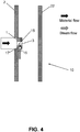
- FIG. 4 provides a cross-sectional view from the side of pair of refining discs 2; 22 and a center ring 1.
- FIG. 5 provides an additional view of a center ring 1 according to this embodiment.
- the curved shape of the wings 3 ensures that the material in the material flow, the latter denoted 39, is lifted to ensure that there is a reduced interaction between the incoming material and the back-travelling steam, the latter denoted 50 in the drawing.
- the material flow 39 follows the rotational motion R of the feeding device and when it impinges on a wing 3 it is raised or lifted by the shape of the wing.
- the steam will evacuate the groove protected by the wing 3 to avoid any contact with the material flow.
- FIG. 6 provides a cross-sectional side view of the center ring 1 illustrated in FIG. 5 .
- the drawing illustrates a material and steam flow that can be obtained by this particular embodiment.
- a material flow 49 is forced into the center ring 1 by a feeding device in the shape of a ribbon feeder 36.
- the wings 3 acts to lift the material upwards and provide protection for the steam flow 50 to evacuate the groove through channels.
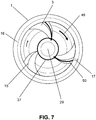
- a particular embodiment of the proposed technology provides a center ring 1 wherein the ends of the plurality of wings 3 that are closest to the center of said through-hole are interconnected by a reinforcing structure 37.
- This embodiment is schematically illustrated in FIG. 7 .
- the reinforcing structure 37 provides additional strength to the wing arrangement and provides additional protection against the substantial forces the wings may experience during operation of the defibrator.
- the reinforcing structure 37 may be a hard material ring that are attached to all wings at their ends. The structure may however display any geometrical shape. The number of wings used determines the most suitable shape.
- the present disclosure has described a number of embodiments of a center ring 1 that enables a reduction of interactions between incoming material flow and back-travelling steam.
- the present disclosure has described a number of embodiments of a center ring 1 that enables a reduction of interactions between incoming material flow and back-travelling steam, it should however also be noted that the proposed technology also provides a refining disc 2 of a defibrator 10 for refining of fibrous material, where the refining disc 2 comprising a center ring 1 according to what has been described above.
- the refining disc 2 may in particular a stator disc.
- the proposed technology also provides a refining disc 2 wherein the center ring 1 is arranged on the refining disc so that the rotational center of the center ring coincide with the rotational center of the refining disc and so that the center ring 1 faces a second refining disc 22 arranged opposite the refining disc 2 during use in a defibrator.
- the proposed technology also relates to a defibrator for refining lignocellulosic material, where the defibrator comprises two oppositely arranged refining discs wherein one of the refining discs is a refining disc according to what has been described above.
- the proposed technology also provides a stator plate comprising a center ring 1 according to what has been described above.
- a stator plate, or a stator is the structure in a defibrator that carries the stator refining disc.
- the present embodiment thus provides an alternative fastening structure for attaching the center ring 1 to the defibrator.
Landscapes
- Engineering & Computer Science (AREA)
- Life Sciences & Earth Sciences (AREA)
- Wood Science & Technology (AREA)
- Mechanical Engineering (AREA)
- Food Science & Technology (AREA)
- Paper (AREA)
Applications Claiming Priority (1)
| Application Number | Priority Date | Filing Date | Title |
|---|---|---|---|
| SE2050147A SE2050147A1 (en) | 2020-02-12 | 2020-02-12 | Center ring provided with wings |
Publications (2)
| Publication Number | Publication Date |
|---|---|
| EP3865621A1 true EP3865621A1 (de) | 2021-08-18 |
| EP3865621B1 EP3865621B1 (de) | 2022-11-23 |
Family
ID=73855881
Family Applications (1)
| Application Number | Title | Priority Date | Filing Date |
|---|---|---|---|
| EP20215624.6A Active EP3865621B1 (de) | 2020-02-12 | 2020-12-18 | Zentralring mit flügeln |
Country Status (5)
| Country | Link |
|---|---|
| US (1) | US11674265B2 (de) |
| EP (1) | EP3865621B1 (de) |
| ES (1) | ES2933450T3 (de) |
| PL (1) | PL3865621T3 (de) |
| SE (1) | SE2050147A1 (de) |
Citations (4)
| Publication number | Priority date | Publication date | Assignee | Title |
|---|---|---|---|---|
| US4221631A (en) | 1977-09-30 | 1980-09-09 | Sca Development Aktiebolag | Method and apparatus for refining fiberous material |
| SE539119C2 (en) | 2015-10-08 | 2017-04-11 | Valmet Oy | Feeding center plate in a pulp or fiber refiner |
| WO2018160115A1 (en) * | 2017-03-03 | 2018-09-07 | Valmet Ab | Steam evacuation in a pulp or fiber refiner |
| WO2018236269A1 (en) * | 2017-06-19 | 2018-12-27 | Valmet Ab | Steam evacuation in a pulp or fiber refiner |
Family Cites Families (3)
| Publication number | Priority date | Publication date | Assignee | Title |
|---|---|---|---|---|
| US4725336A (en) * | 1985-01-31 | 1988-02-16 | Swm Corporation | Refiner apparatus with integral steam separator |
| CA2507321C (en) * | 2004-07-08 | 2012-06-26 | Andritz Inc. | High intensity refiner plate with inner fiberizing zone |
| SE537031C2 (sv) * | 2013-03-12 | 2014-12-09 | Valmet Oy | Centerplatta i massaraffinör med bågformade bommar |
-
2020
- 2020-02-12 SE SE2050147A patent/SE2050147A1/en unknown
- 2020-12-18 ES ES20215624T patent/ES2933450T3/es active Active
- 2020-12-18 PL PL20215624.6T patent/PL3865621T3/pl unknown
- 2020-12-18 EP EP20215624.6A patent/EP3865621B1/de active Active
-
2021
- 2021-02-03 US US17/166,211 patent/US11674265B2/en active Active
Patent Citations (4)
| Publication number | Priority date | Publication date | Assignee | Title |
|---|---|---|---|---|
| US4221631A (en) | 1977-09-30 | 1980-09-09 | Sca Development Aktiebolag | Method and apparatus for refining fiberous material |
| SE539119C2 (en) | 2015-10-08 | 2017-04-11 | Valmet Oy | Feeding center plate in a pulp or fiber refiner |
| WO2018160115A1 (en) * | 2017-03-03 | 2018-09-07 | Valmet Ab | Steam evacuation in a pulp or fiber refiner |
| WO2018236269A1 (en) * | 2017-06-19 | 2018-12-27 | Valmet Ab | Steam evacuation in a pulp or fiber refiner |
Also Published As
| Publication number | Publication date |
|---|---|
| US11674265B2 (en) | 2023-06-13 |
| ES2933450T3 (es) | 2023-02-09 |
| SE543499C2 (en) | 2021-03-09 |
| SE2050147A1 (en) | 2021-03-09 |
| US20210246610A1 (en) | 2021-08-12 |
| EP3865621B1 (de) | 2022-11-23 |
| PL3865621T3 (pl) | 2022-12-27 |
Similar Documents
| Publication | Publication Date | Title |
|---|---|---|
| EP1647330B1 (de) | Refinerplatte mit Düseneinlass | |
| US5893525A (en) | Refiner plate with variable pitch | |
| EP2722433B1 (de) | Refinerplattensegment zur Verfeinerung von Lignocellulosematerial | |
| US10378149B2 (en) | Refiner plate segment with pre-dam | |
| CN109778581B (zh) | 纤维精磨机中的精磨机区段 | |
| EP4063561B1 (de) | Refinersegment | |
| EP3359728B1 (de) | Beschickungsmittelplatte in einem zellstoff- oder faserrefiner | |
| EP3865621B1 (de) | Zentralring mit flügeln | |
| US11905659B2 (en) | Refiner segment having bar weakening sections | |
| US11440017B2 (en) | Steam evacuation in a pulp or fiber refiner | |
| EP3642413B1 (de) | Dampfevakuierung in einem zellstoff- oder faserraffinierer | |
| US6227471B1 (en) | Feeding element for fibrous material | |
| EP3827126B1 (de) | Refinersegment mit variierendem tiefenprofil | |
| CN111182973B (zh) | 设有带边缘产生棒条腔体的精磨棒条的精磨板 |
Legal Events
| Date | Code | Title | Description |
|---|---|---|---|
| PUAI | Public reference made under article 153(3) epc to a published international application that has entered the european phase |
Free format text: ORIGINAL CODE: 0009012 |
|
| STAA | Information on the status of an ep patent application or granted ep patent |
Free format text: STATUS: THE APPLICATION HAS BEEN PUBLISHED |
|
| AK | Designated contracting states |
Kind code of ref document: A1 Designated state(s): AL AT BE BG CH CY CZ DE DK EE ES FI FR GB GR HR HU IE IS IT LI LT LU LV MC MK MT NL NO PL PT RO RS SE SI SK SM TR |
|
| STAA | Information on the status of an ep patent application or granted ep patent |
Free format text: STATUS: REQUEST FOR EXAMINATION WAS MADE |
|
| 17P | Request for examination filed |
Effective date: 20220218 |
|
| RBV | Designated contracting states (corrected) |
Designated state(s): AL AT BE BG CH CY CZ DE DK EE ES FI FR GB GR HR HU IE IS IT LI LT LU LV MC MK MT NL NO PL PT RO RS SE SI SK SM TR |
|
| GRAP | Despatch of communication of intention to grant a patent |
Free format text: ORIGINAL CODE: EPIDOSNIGR1 |
|
| STAA | Information on the status of an ep patent application or granted ep patent |
Free format text: STATUS: GRANT OF PATENT IS INTENDED |
|
| RIC1 | Information provided on ipc code assigned before grant |
Ipc: B02C 7/12 20060101ALN20220622BHEP Ipc: D21D 1/30 20060101AFI20220622BHEP |
|
| INTG | Intention to grant announced |
Effective date: 20220707 |
|
| GRAS | Grant fee paid |
Free format text: ORIGINAL CODE: EPIDOSNIGR3 |
|
| GRAA | (expected) grant |
Free format text: ORIGINAL CODE: 0009210 |
|
| STAA | Information on the status of an ep patent application or granted ep patent |
Free format text: STATUS: THE PATENT HAS BEEN GRANTED |
|
| AK | Designated contracting states |
Kind code of ref document: B1 Designated state(s): AL AT BE BG CH CY CZ DE DK EE ES FI FR GB GR HR HU IE IS IT LI LT LU LV MC MK MT NL NO PL PT RO RS SE SI SK SM TR |
|
| REG | Reference to a national code |
Ref country code: GB Ref legal event code: FG4D |
|
| REG | Reference to a national code |
Ref country code: CH Ref legal event code: EP |
|
| REG | Reference to a national code |
Ref country code: AT Ref legal event code: REF Ref document number: 1533208 Country of ref document: AT Kind code of ref document: T Effective date: 20221215 Ref country code: DE Ref legal event code: R096 Ref document number: 602020006453 Country of ref document: DE |
|
| REG | Reference to a national code |
Ref country code: IE Ref legal event code: FG4D |
|
| REG | Reference to a national code |
Ref country code: ES Ref legal event code: FG2A Ref document number: 2933450 Country of ref document: ES Kind code of ref document: T3 Effective date: 20230209 |
|
| REG | Reference to a national code |
Ref country code: LT Ref legal event code: MG9D |
|
| REG | Reference to a national code |
Ref country code: NL Ref legal event code: MP Effective date: 20221123 |
|
| PG25 | Lapsed in a contracting state [announced via postgrant information from national office to epo] |
Ref country code: SE Free format text: LAPSE BECAUSE OF FAILURE TO SUBMIT A TRANSLATION OF THE DESCRIPTION OR TO PAY THE FEE WITHIN THE PRESCRIBED TIME-LIMIT Effective date: 20221123 Ref country code: PT Free format text: LAPSE BECAUSE OF FAILURE TO SUBMIT A TRANSLATION OF THE DESCRIPTION OR TO PAY THE FEE WITHIN THE PRESCRIBED TIME-LIMIT Effective date: 20230323 Ref country code: NO Free format text: LAPSE BECAUSE OF FAILURE TO SUBMIT A TRANSLATION OF THE DESCRIPTION OR TO PAY THE FEE WITHIN THE PRESCRIBED TIME-LIMIT Effective date: 20230223 Ref country code: LT Free format text: LAPSE BECAUSE OF FAILURE TO SUBMIT A TRANSLATION OF THE DESCRIPTION OR TO PAY THE FEE WITHIN THE PRESCRIBED TIME-LIMIT Effective date: 20221123 |
|
| PG25 | Lapsed in a contracting state [announced via postgrant information from national office to epo] |
Ref country code: RS Free format text: LAPSE BECAUSE OF FAILURE TO SUBMIT A TRANSLATION OF THE DESCRIPTION OR TO PAY THE FEE WITHIN THE PRESCRIBED TIME-LIMIT Effective date: 20221123 Ref country code: LV Free format text: LAPSE BECAUSE OF FAILURE TO SUBMIT A TRANSLATION OF THE DESCRIPTION OR TO PAY THE FEE WITHIN THE PRESCRIBED TIME-LIMIT Effective date: 20221123 Ref country code: IS Free format text: LAPSE BECAUSE OF FAILURE TO SUBMIT A TRANSLATION OF THE DESCRIPTION OR TO PAY THE FEE WITHIN THE PRESCRIBED TIME-LIMIT Effective date: 20230323 Ref country code: HR Free format text: LAPSE BECAUSE OF FAILURE TO SUBMIT A TRANSLATION OF THE DESCRIPTION OR TO PAY THE FEE WITHIN THE PRESCRIBED TIME-LIMIT Effective date: 20221123 Ref country code: GR Free format text: LAPSE BECAUSE OF FAILURE TO SUBMIT A TRANSLATION OF THE DESCRIPTION OR TO PAY THE FEE WITHIN THE PRESCRIBED TIME-LIMIT Effective date: 20230224 |
|
| PG25 | Lapsed in a contracting state [announced via postgrant information from national office to epo] |
Ref country code: NL Free format text: LAPSE BECAUSE OF FAILURE TO SUBMIT A TRANSLATION OF THE DESCRIPTION OR TO PAY THE FEE WITHIN THE PRESCRIBED TIME-LIMIT Effective date: 20221123 |
|
| P01 | Opt-out of the competence of the unified patent court (upc) registered |
Effective date: 20230607 |
|
| PG25 | Lapsed in a contracting state [announced via postgrant information from national office to epo] |
Ref country code: SM Free format text: LAPSE BECAUSE OF FAILURE TO SUBMIT A TRANSLATION OF THE DESCRIPTION OR TO PAY THE FEE WITHIN THE PRESCRIBED TIME-LIMIT Effective date: 20221123 Ref country code: RO Free format text: LAPSE BECAUSE OF FAILURE TO SUBMIT A TRANSLATION OF THE DESCRIPTION OR TO PAY THE FEE WITHIN THE PRESCRIBED TIME-LIMIT Effective date: 20221123 Ref country code: IT Free format text: LAPSE BECAUSE OF NON-PAYMENT OF DUE FEES Effective date: 20221218 Ref country code: EE Free format text: LAPSE BECAUSE OF FAILURE TO SUBMIT A TRANSLATION OF THE DESCRIPTION OR TO PAY THE FEE WITHIN THE PRESCRIBED TIME-LIMIT Effective date: 20221123 Ref country code: DK Free format text: LAPSE BECAUSE OF FAILURE TO SUBMIT A TRANSLATION OF THE DESCRIPTION OR TO PAY THE FEE WITHIN THE PRESCRIBED TIME-LIMIT Effective date: 20221123 Ref country code: CZ Free format text: LAPSE BECAUSE OF FAILURE TO SUBMIT A TRANSLATION OF THE DESCRIPTION OR TO PAY THE FEE WITHIN THE PRESCRIBED TIME-LIMIT Effective date: 20221123 |
|
| REG | Reference to a national code |
Ref country code: DE Ref legal event code: R097 Ref document number: 602020006453 Country of ref document: DE Ref country code: BE Ref legal event code: MM Effective date: 20221231 |
|
| PG25 | Lapsed in a contracting state [announced via postgrant information from national office to epo] |
Ref country code: SK Free format text: LAPSE BECAUSE OF FAILURE TO SUBMIT A TRANSLATION OF THE DESCRIPTION OR TO PAY THE FEE WITHIN THE PRESCRIBED TIME-LIMIT Effective date: 20221123 Ref country code: LU Free format text: LAPSE BECAUSE OF NON-PAYMENT OF DUE FEES Effective date: 20221218 Ref country code: AL Free format text: LAPSE BECAUSE OF FAILURE TO SUBMIT A TRANSLATION OF THE DESCRIPTION OR TO PAY THE FEE WITHIN THE PRESCRIBED TIME-LIMIT Effective date: 20221123 |
|
| PLBE | No opposition filed within time limit |
Free format text: ORIGINAL CODE: 0009261 |
|
| STAA | Information on the status of an ep patent application or granted ep patent |
Free format text: STATUS: NO OPPOSITION FILED WITHIN TIME LIMIT |
|
| PG25 | Lapsed in a contracting state [announced via postgrant information from national office to epo] |
Ref country code: IE Free format text: LAPSE BECAUSE OF NON-PAYMENT OF DUE FEES Effective date: 20221218 |
|
| 26N | No opposition filed |
Effective date: 20230824 |
|
| PG25 | Lapsed in a contracting state [announced via postgrant information from national office to epo] |
Ref country code: SI Free format text: LAPSE BECAUSE OF FAILURE TO SUBMIT A TRANSLATION OF THE DESCRIPTION OR TO PAY THE FEE WITHIN THE PRESCRIBED TIME-LIMIT Effective date: 20221123 Ref country code: BE Free format text: LAPSE BECAUSE OF NON-PAYMENT OF DUE FEES Effective date: 20221231 |
|
| PG25 | Lapsed in a contracting state [announced via postgrant information from national office to epo] |
Ref country code: IT Free format text: LAPSE BECAUSE OF NON-PAYMENT OF DUE FEES Effective date: 20221218 |
|
| PGRI | Patent reinstated in contracting state [announced from national office to epo] |
Ref country code: IT Effective date: 20221231 |
|
| REG | Reference to a national code |
Ref country code: AT Ref legal event code: UEP Ref document number: 1533208 Country of ref document: AT Kind code of ref document: T Effective date: 20221123 |
|
| PG25 | Lapsed in a contracting state [announced via postgrant information from national office to epo] |
Ref country code: CY Free format text: LAPSE BECAUSE OF FAILURE TO SUBMIT A TRANSLATION OF THE DESCRIPTION OR TO PAY THE FEE WITHIN THE PRESCRIBED TIME-LIMIT Effective date: 20221123 |
|
| PG25 | Lapsed in a contracting state [announced via postgrant information from national office to epo] |
Ref country code: MK Free format text: LAPSE BECAUSE OF FAILURE TO SUBMIT A TRANSLATION OF THE DESCRIPTION OR TO PAY THE FEE WITHIN THE PRESCRIBED TIME-LIMIT Effective date: 20221123 |
|
| PG25 | Lapsed in a contracting state [announced via postgrant information from national office to epo] |
Ref country code: MC Free format text: LAPSE BECAUSE OF FAILURE TO SUBMIT A TRANSLATION OF THE DESCRIPTION OR TO PAY THE FEE WITHIN THE PRESCRIBED TIME-LIMIT Effective date: 20221123 |
|
| PG25 | Lapsed in a contracting state [announced via postgrant information from national office to epo] |
Ref country code: TR Free format text: LAPSE BECAUSE OF FAILURE TO SUBMIT A TRANSLATION OF THE DESCRIPTION OR TO PAY THE FEE WITHIN THE PRESCRIBED TIME-LIMIT Effective date: 20221123 Ref country code: MC Free format text: LAPSE BECAUSE OF FAILURE TO SUBMIT A TRANSLATION OF THE DESCRIPTION OR TO PAY THE FEE WITHIN THE PRESCRIBED TIME-LIMIT Effective date: 20221123 |
|
| PG25 | Lapsed in a contracting state [announced via postgrant information from national office to epo] |
Ref country code: BG Free format text: LAPSE BECAUSE OF FAILURE TO SUBMIT A TRANSLATION OF THE DESCRIPTION OR TO PAY THE FEE WITHIN THE PRESCRIBED TIME-LIMIT Effective date: 20221123 |
|
| REG | Reference to a national code |
Ref country code: CH Ref legal event code: PL |
|
| PG25 | Lapsed in a contracting state [announced via postgrant information from national office to epo] |
Ref country code: MT Free format text: LAPSE BECAUSE OF FAILURE TO SUBMIT A TRANSLATION OF THE DESCRIPTION OR TO PAY THE FEE WITHIN THE PRESCRIBED TIME-LIMIT Effective date: 20221123 |
|
| PG25 | Lapsed in a contracting state [announced via postgrant information from national office to epo] |
Ref country code: CH Free format text: LAPSE BECAUSE OF NON-PAYMENT OF DUE FEES Effective date: 20231231 |
|
| PG25 | Lapsed in a contracting state [announced via postgrant information from national office to epo] |
Ref country code: CH Free format text: LAPSE BECAUSE OF NON-PAYMENT OF DUE FEES Effective date: 20231231 |
|
| PG25 | Lapsed in a contracting state [announced via postgrant information from national office to epo] |
Ref country code: HU Free format text: LAPSE BECAUSE OF FAILURE TO SUBMIT A TRANSLATION OF THE DESCRIPTION OR TO PAY THE FEE WITHIN THE PRESCRIBED TIME-LIMIT; INVALID AB INITIO Effective date: 20201218 |
|
| GBPC | Gb: european patent ceased through non-payment of renewal fee |
Effective date: 20241218 |
|
| PG25 | Lapsed in a contracting state [announced via postgrant information from national office to epo] |
Ref country code: GB Free format text: LAPSE BECAUSE OF NON-PAYMENT OF DUE FEES Effective date: 20241218 |
|
| PGFP | Annual fee paid to national office [announced via postgrant information from national office to epo] |
Ref country code: AT Payment date: 20251219 Year of fee payment: 6 |
|
| PGFP | Annual fee paid to national office [announced via postgrant information from national office to epo] |
Ref country code: IT Payment date: 20251212 Year of fee payment: 6 Ref country code: FI Payment date: 20251216 Year of fee payment: 6 |
|
| PGFP | Annual fee paid to national office [announced via postgrant information from national office to epo] |
Ref country code: FR Payment date: 20251211 Year of fee payment: 6 |
|
| PGFP | Annual fee paid to national office [announced via postgrant information from national office to epo] |
Ref country code: PL Payment date: 20251118 Year of fee payment: 6 |
|
| PGFP | Annual fee paid to national office [announced via postgrant information from national office to epo] |
Ref country code: ES Payment date: 20260122 Year of fee payment: 6 |
|
| PGFP | Annual fee paid to national office [announced via postgrant information from national office to epo] |
Ref country code: DE Payment date: 20251222 Year of fee payment: 6 |