EP3865666B1 - Pale pour turbomachine avec un carénage - Google Patents
Pale pour turbomachine avec un carénage Download PDFInfo
- Publication number
- EP3865666B1 EP3865666B1 EP21152941.7A EP21152941A EP3865666B1 EP 3865666 B1 EP3865666 B1 EP 3865666B1 EP 21152941 A EP21152941 A EP 21152941A EP 3865666 B1 EP3865666 B1 EP 3865666B1
- Authority
- EP
- European Patent Office
- Prior art keywords
- shroud
- blade
- supporting wall
- hardfacing
- Prior art date
- Legal status (The legal status is an assumption and is not a legal conclusion. Google has not performed a legal analysis and makes no representation as to the accuracy of the status listed.)
- Active
Links
Images

Classifications
-
- F—MECHANICAL ENGINEERING; LIGHTING; HEATING; WEAPONS; BLASTING
- F01—MACHINES OR ENGINES IN GENERAL; ENGINE PLANTS IN GENERAL; STEAM ENGINES
- F01D—NON-POSITIVE DISPLACEMENT MACHINES OR ENGINES, e.g. STEAM TURBINES
- F01D5/00—Blades; Blade-carrying members; Heating, heat-insulating, cooling or antivibration means on the blades or the members
- F01D5/12—Blades
- F01D5/14—Form or construction
- F01D5/147—Construction, i.e. structural features, e.g. of weight-saving hollow blades
-
- F—MECHANICAL ENGINEERING; LIGHTING; HEATING; WEAPONS; BLASTING
- F01—MACHINES OR ENGINES IN GENERAL; ENGINE PLANTS IN GENERAL; STEAM ENGINES
- F01D—NON-POSITIVE DISPLACEMENT MACHINES OR ENGINES, e.g. STEAM TURBINES
- F01D5/00—Blades; Blade-carrying members; Heating, heat-insulating, cooling or antivibration means on the blades or the members
- F01D5/12—Blades
- F01D5/22—Blade-to-blade connections, e.g. for damping vibrations
- F01D5/225—Blade-to-blade connections, e.g. for damping vibrations by shrouding
-
- F—MECHANICAL ENGINEERING; LIGHTING; HEATING; WEAPONS; BLASTING
- F01—MACHINES OR ENGINES IN GENERAL; ENGINE PLANTS IN GENERAL; STEAM ENGINES
- F01D—NON-POSITIVE DISPLACEMENT MACHINES OR ENGINES, e.g. STEAM TURBINES
- F01D11/00—Preventing or minimising internal leakage of working-fluid, e.g. between stages
- F01D11/08—Preventing or minimising internal leakage of working-fluid, e.g. between stages for sealing space between rotor blade tips and stator
- F01D11/10—Preventing or minimising internal leakage of working-fluid, e.g. between stages for sealing space between rotor blade tips and stator using sealing fluid, e.g. steam
-
- F—MECHANICAL ENGINEERING; LIGHTING; HEATING; WEAPONS; BLASTING
- F01—MACHINES OR ENGINES IN GENERAL; ENGINE PLANTS IN GENERAL; STEAM ENGINES
- F01D—NON-POSITIVE DISPLACEMENT MACHINES OR ENGINES, e.g. STEAM TURBINES
- F01D5/00—Blades; Blade-carrying members; Heating, heat-insulating, cooling or antivibration means on the blades or the members
- F01D5/12—Blades
- F01D5/14—Form or construction
- F01D5/16—Form or construction for counteracting blade vibration
-
- F—MECHANICAL ENGINEERING; LIGHTING; HEATING; WEAPONS; BLASTING
- F05—INDEXING SCHEMES RELATING TO ENGINES OR PUMPS IN VARIOUS SUBCLASSES OF CLASSES F01-F04
- F05D—INDEXING SCHEME FOR ASPECTS RELATING TO NON-POSITIVE-DISPLACEMENT MACHINES OR ENGINES, GAS-TURBINES OR JET-PROPULSION PLANTS
- F05D2260/00—Function
- F05D2260/94—Functionality given by mechanical stress related aspects such as low cycle fatigue [LCF] of high cycle fatigue [HCF]
- F05D2260/941—Functionality given by mechanical stress related aspects such as low cycle fatigue [LCF] of high cycle fatigue [HCF] particularly aimed at mechanical or thermal stress reduction
Definitions
- the present invention refers to a blade for a turbomachine comprising a shroud which is positioned on a tip side of the blade having an outer surface with at least one circumferential web arranged thereon, at least one first pocket recessed in the outer surface and a hardfacing provided on at least one edge of the shroud.
- Blades for turbomachines comprising a shroud which is positioned on a blade tip side of the blade are known in the prior art.
- the blades are arranged next to each other and contact each other at contact areas arranged at edges of the shroud. These contact areas are often provided with a hardfacing in order to keep mechanical abrasion at a low level. While good vibration qualities are achievable by providing the blades with an outer shroud, the weight or mass of the shroud itself increases the centrifugal load on the blade during rotation around the engine axis, thereby causing higher stresses in the blade root and the airfoil.
- the weight or mass and in particular the balance of the weight or mass of the outer shroud contribute significantly to the load and stresses acting on a blade. Therefore, the weight or mass of the outer shroud has a substantial influence on excessive loading on the blade root and the disc and such affects its overall lifetime.
- the invention proposes a blade for a turbomachine comprising a shroud which is positioned on a tip side of the blade having an outer surface having at least one circumferential web arranged thereon, at least one pocket recessed in the outer surface of the shroud and a hardfacing provided on at least one edge of the shroud.
- a first pocket recessed in the outer surface is arranged adjacent to the hardfacing, wherein the first pocket is open to the edge and wherein between the first pocket and the hardfacing a supporting wall is arranged for supporting the hardfacing during contact of the edge of the shroud with the edge of another shroud.
- the blade for a turbomachine comprises a shroud which is positioned at its tip side and which extends essentially in the circumferential direction of rotation of the blade disk.
- the radial outer surface of the shroud is hereinafter referred to as the outer surface of the shroud.
- At least one circumferential web is arranged circumferentially aligned with regard to the rotation direction of the blade disk and turbomachine, respectively. Usually the radial thickness of such webs is constant in circumferential direction.
- the design of shrouds having at least one circumferentially aligned web is called dogbone-shaped. Such a design permits a high degree of reinforcement in both the circumferential direction and the axial direction.
- the shroud further comprises a hardfacing provided on at least one edge of the shroud.
- a hardfacing provided on at least one edge of the shroud.
- the blades are arranged next to each other and contact each other at contact areas arranged at adjacent edges of the shrouds.
- hardfacing elements are used which are welded into prepared recesses. The forces resulting from contact between the shrouds are transferred via the hardfacing into the shroud and thus into the blade.
- the hardfacing is supported by a supporting wall.
- a first pocket recessed in the outer surface and open to the edge of the shroud is arranged at a distance from the hardfacing at the other side of a supporting wall.
- the combination of a reduced load of the blade resulting from the open first pocket at the side edge of the shroud, and the supporting wall also serves for preventing creep curling of the edge of the shroud.
- a side face of the first pocket joins the supporting wall with a radius corresponding at least to the length of the shorter extension of the supporting wall.
- the radius can be at least 1.5 or 2 times the length of the shorter extension of the supporting wall, and can be at most to 1.5 times the length of the larger extension of the supporting wall, in particular at most to 1.4 or 1.3 times the length of the larger extension of the supporting wall.
- the radius of the side face of the pocket is about 1.2 times the extension of the hardfacing with respect to (along) the supporting wall, e.g. in the rage of 1.2 ⁇ 0.1 times of this length.
- This ratio between the radius of the side face of the pocket and the extension of the hardfacing allows for a particular beneficial distribution of the stress within the shroud of the blade.
- the radius of the side face of the pocket enables a smooth stress distribution adjacent to the hardfacing area.
- a larger radius distributes the stress to a larger area.
- the radius can range from 1.5 to 4.0 mm.
- the radius runout joins the supporting wall not yet being parallel to the supporting wall.
- the proposed blade for a turbomachine allows a more balanced and lightweight design of the shroud having a hardfacing arranged on at least one edge but also sufficient support for the hardfacing during contacting the adjacent blade and allows for an advantageous stress distribution.
- At least one further pocket is arranged at the outer surface of the shroud, wherein the area between two pockets forms a reinforcement rib.
- the provision of further pockets allows to further reduce the weight of the outer shroud.
- the area between two pockets forms reinforcement ribs which have to be arranged and designed according to strength requirements of the shroud.
- Additional pockets and/or ribs can allow for a particularly advantageous designs in terms of stiffness, weight and stress distribution.
- the shroud further comprises a closed second pocket and an axially adjacent closed third pocket which are separated by a first reinforcement rib.
- “Closed pockets” are confined in lateral direction, i.e. in circumferential and/or axial direction of the turbomachine, e.g. by reinforcements ribs and/or fins, and are thus not open to an edge of the shroud.
- the lateral direction is perpendicular to the radial direction.
- the second pocket and the first pocket can be arranged circumferentially adjacent and can be separated by a second reinforcement rib.
- the shroud can further comprise an open fourth pocket being arranged circumferentially opposite to the first pocket.
- the fourth pocket and the second pocket can be arranged circumferentially adjacent and can be separated by a third reinforcement rib.
- the shroud can further comprise an open fifth pocket being arranged circumferentially adjacent to the third pocket and/or axially opposite to the first pocket and being separated from the fifth pocket by a fourth reinforcement rib.
- the supporting wall has a substantially rectangular or rhomboid shape in top view of the shroud.
- the supporting wall having the rectangular or rhomboid shape serves on the one hand to absorb the forces acting on the hardfacing and on the other hand to transmit and/ or distribute them within the shroud.
- substantially rectangular or rhomboid means that the supporting wall has two substantially parallel sides, one side facing the hardfacing and the other side facing the first pocket.
- the edge of the shroud forms one front side of the substantial rectangular or rhomboid shape and an imaginary side, arranged approximately at the end of the hardfacing, in particular parallel to the front side forms the (imaginary) second end side of the rectangular or rhomboid shape.
- the sides facing the hardfacing and the first pocket include an angle between 0° (parallel) and 30°.
- the shorter side of the supporting wall is arranged at the edge of the shroud.
- usually the shorter side of the hardfacing is arranged next to and in line with the front side of the supporting wall at the edge of the shroud such, that the longer side of the hardfacing is supported by the supporting wall.
- the first pocket has substantially the same extension as the hardfacing with respect to the supporting wall. Also in this design the supporting wall serves apart from supporting the hardfacing also for reinforcement of the shroud with regard to the material reduction resulting from the first pocket.
- the supporting wall extends at an angle ⁇ with respect to the circumferential direction. This design allows the supporting wall to absorb forces oriented in circumferential direction and acting on the hardfacing. The closer the angle ⁇ is to 90° to the circumferential direction, the more circumferentially directed force the supporting wall can absorb from the hardfacing, in particular forces resulting from contacting a shroud of another blade.
- the first pocket extends from the supporting wall to the circumferential web.
- the open first pocket extends along a major proportion of the edge of the shroud starting from the supporting wall.
- the depth of the first pocket with regard to the outer surface is in the range of 0.2 to 0.7 times the total thickness of the shroud in the area of the supporting wall. Also this design enables relatively large weight reductions of the shroud in particular on at least one edge while maintaining the required strength.
- the depth of the first pocket is about 0.5 times the total thickness of the shroud in the area of the supporting wall. Also this design enables relatively large weight reductions of the shroud in particular on at least one edge while maintaining the required strength.
- the edges of the shroud have an essentially Z-shaped design.
- two adjacent shrouds and contact surfaces, respectively of the shroud are essentially Z-shaped for contacting corresponding contact surfaces of adj acent arranged blades and shrouds, respectively.
- This design allows adjacent arranged blades comprising a Z-shaped shroud to support each other during operation of the turbomachine or disk provided with accordingly designed blades, thus providing mechanical stability. Undesired bending or twisting of the shrouds and blades, respectively is likewise reduced.
- the invention refers to a turbomachine comprising a blade comprising features and characteristics as described in the preceding disclosure referring to a blade for a turbomachine.
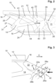
- Fig. 1 shows a schematic representation of an exemplary blade 10 for a turbomachine having a shroud 12 positioned on the tip side of the blade 10.
- the shroud 12 comprises an outer surface 14 with two circumferential webs 16 arranged thereon.
- This design is also called “dogbone”-design allowing a high degree of reinforcement of the shroud 12 and the blade 10, respectively in both the circumferential direction and the axial direction.
- the blade root 18 is arranged on the opposite side of the blade tip, where the shroud 12 is positioned.
- the airfoil 17 of the blade 10 is arranged.
- Fig. 2 shows a top view on the shroud 12 of the exemplary blade 10 shown in Fig 1 .
- the shroud of the exemplary embodiment comprises several pockets 21, 22, 23, 24, 25 recessed in the outer surface 14 and two hardfacings 26, 27 provided at each edge 31, 32 of the shroud 12.
- a fist pocket 22 recessed in the outer surface 14 is open to the edge 32 and is arranged adjacent to the hardfacing 26.
- a supporting wall 28 is arranged for supporting the hardfacing 28 during contact of the edge 32 of the shroud 12 with the edge of another shroud 11 (schematically indicated at the right hand sight).
- the shroud 12 of the blade 10 also comprises further pockets 21, 23, 24, 25 which are arranged at the outer surface 14 of the shroud 12 and the areas between two pockets 21, 22, 23, 24, 25 form reinforcement ribs 41, 42, 43, 44.
- the edges 31, 32 of the exemplary embodiment of the shroud 12 have an essentially Z-shaped design.
- the shroud 12 further comprises a closed second pocket 21 and an axially adjacent closed third pocket 24 which are separated by a first reinforcement rib 44.
- the second pocket 21 and the first pocket 22 are arranged circumferentially adjacent and separated by a second reinforcement rib 42.
- the shroud 12 further comprises an open fourth pocket 25 which is arranged circumferentially opposite to the first pocket 22.
- the fourth pocket 25 and the second pocket 21 are arranged circumferentially adjacent and separated by a third reinforcement rib 41.
- the shroud 12 further comprises an open fifth pocket 23 which is arranged circumferentially adjacent to the third pocket 24 and axially opposite to the first pocket 22 and which is separated from the fifth pocket 23 by a fourth reinforcement rib 43.
- Fig. 3 shows a detail of the top view of the shroud of Fig. 2.
- Fig. 3 shows the edge 32 of shroud 12 and the first pocket 22 in more detail.
- the supporting wall 28 has a substantially rhomboid shape in top view of the shroud 12, wherein the shorter side of the supporting wall 28 is arranged at the edge 32 of the shroud 12.
- the first pocket 22 is recessed into the outer surface 14 of the shroud 12 and has substantially the same extension as the hardfacing 26 with respect to the supporting wall 28.
- the supporting wall 28 extends at an angle ⁇ with respect to the circumferential direction C. As is shown in Fig. 3 , the supporting wall 28 is arranged at an angle ⁇ of about 45° with regard to the circumferential direction. This design allows the supporting wall 28 to absorb forces F oriented in circumferential direction C and acting on the hardfacing 26 as in particular forces resulting from contacting a shroud 11 of another blade.
- the side face 22a of the first pocket 22 joins the supporting wall 28 with a radius R in particular corresponding at least to the length of the shorter extension 28a of the supporting wall 28 and at most to 1.5 times to the length of the larger extension 28b of the supporting wall 28.
- the radius R of the side face 22a of the first pocket 22 is about 1.2 times the extension 26a of the hardfacing 26 with respect to the supporting wall 28.
- the first pocket 22 of the exemplary embodiment shown in Fig. 3 extends from the supporting wall 28 to the circumferential web 16.
- the depth of the first pocket 22 with regard to the outer surface 14 is in the range of 0.2 to 0.7 times and in particular about 0.5 times the total thickness of the shroud 12 in the area of the supporting wall 28.
Landscapes
- Engineering & Computer Science (AREA)
- Mechanical Engineering (AREA)
- General Engineering & Computer Science (AREA)
- Architecture (AREA)
- Structures Of Non-Positive Displacement Pumps (AREA)
Claims (13)
- Pale pour une turbomachine comprenant un carénage (12) qui est positionné sur un côté pointe de la pale (10), présentant une surface extérieure (14) présentant au moins une bande circonférentielle (16) agencée sur celle-ci, au moins une poche (21, 22, 23, 24, 25) en retrait dans la surface extérieure (14) et un surfaçage de renfort (26, 27) disposé sur au moins un bord (31, 32) du carénage (12), une première poche (22) en retrait dans la surface extérieure (14) étant agencée de manière adjacente au surfaçage de renfort (26), dans laquelle la première poche (22) est ouverte sur le bord (32) et dans lequel entre la première poche (22) et le surfaçage de renfort (26), une paroi support (28) est agencée afin de supporter le surfaçage de renfort (26) pendant le contact du bord (32) du carénage (12) avec le bord d'un autre carénage (11),
caractérisée en ce qu'une face latérale (22a) de la première poche (22) rejoint la paroi support (28) avec un rayon (R) correspondant au moins à la longueur de la plus courte extension (28a) de la paroi support (28) et au plus à 1,5 fois la longueur de la plus grande extension (28b) de la paroi support (28) et en ce que le carénage (12) comprend en outre une deuxième poche (21) fermée et une troisième poche (24) fermée axialement adjacente qui sont séparées par une première nervure de renforcement (44). - Pale pour une turbomachine selon la revendication 1,
caractérisée en ce que la deuxième poche (21) et la première poche (22) sont agencées de manière circonférentiellement adjacente et séparées par une deuxième nervure de renforcement (42). - Pale pour une turbomachine selon l'une des revendications précédentes,
caractérisée en ce que le carénage (12) comprend en outre une quatrième poche (25) ouverte, agencée de manière circonférentiellement opposée à la première poche (22). - Pale pour une turbomachine selon la revendication 3,
caractérisée en ce que la quatrième poche (25) et la deuxième poche (21) sont agencées de manière circonférentiellement adjacente et séparées par une troisième nervure de renforcement (41). - Pale pour une turbomachine selon l'une des revendications précédentes,
caractérisée en ce que le carénage (12) comprend en outre une cinquième poche (23) ouverte, agencée de manière circonférentiellement adjacente à la troisième poche (24) et/ou axialement opposée à la première poche (22) et séparée de la cinquième poche (23) par une quatrième nervure de renforcement (43). - Pale pour une turbomachine selon l'une des revendications précédentes,
caractérisée en ce que la paroi support (28) présente une forme sensiblement rectangulaire ou rhomboïdale en vue de dessus du carénage (12). - Pale pour une turbomachine selon la revendication 6,
caractérisée en ce que le côté le plus court de la paroi support (28) est agencé au niveau du bord (32) du carénage (12). - Pale pour une turbomachine selon l'une des revendications précédentes,
caractérisée en ce que la première poche (22) présente sensiblement la même extension que celle du surfaçage de renfort (26) par rapport à la paroi support (28). - Pale pour une turbomachine selon l'une des revendications précédentes,
caractérisée en ce que la paroi support (28) s'étend selon un angle (α) par rapport à la direction circonférentielle (C). - Pale pour une turbomachine selon l'une des revendications précédentes,
caractérisée en ce que la première poche (22) s'étend à partir de la paroi support (28) vers la bande circonférentielle (12). - Pale pour une turbomachine selon l'une des revendications précédentes,
caractérisée en ce que la profondeur de la première poche (22) ou d'au moins l'une parmi la deuxième à la cinquième poche (21, 24, 25, 23) par rapport à la surface extérieure (14) est située dans la plage de 0,2 à 0,7 fois l'épaisseur totale du carénage (12) dans la zone de la paroi support (28). - Pale pour une turbomachine selon l'une des revendications précédentes,
caractérisée en ce que les bords (31, 32) du carénage (12) présentent une forme essentiellement en Z. - Turbomachine comprenant une pale (10) selon l'une des revendications 1 à 11.
Applications Claiming Priority (1)
| Application Number | Priority Date | Filing Date | Title |
|---|---|---|---|
| EP20156506.6A EP3865665A1 (fr) | 2020-02-11 | 2020-02-11 | Pale pour turbomachine avec un carénage |
Publications (2)
| Publication Number | Publication Date |
|---|---|
| EP3865666A1 EP3865666A1 (fr) | 2021-08-18 |
| EP3865666B1 true EP3865666B1 (fr) | 2024-06-05 |
Family
ID=69570601
Family Applications (2)
| Application Number | Title | Priority Date | Filing Date |
|---|---|---|---|
| EP20156506.6A Withdrawn EP3865665A1 (fr) | 2020-02-11 | 2020-02-11 | Pale pour turbomachine avec un carénage |
| EP21152941.7A Active EP3865666B1 (fr) | 2020-02-11 | 2021-01-22 | Pale pour turbomachine avec un carénage |
Family Applications Before (1)
| Application Number | Title | Priority Date | Filing Date |
|---|---|---|---|
| EP20156506.6A Withdrawn EP3865665A1 (fr) | 2020-02-11 | 2020-02-11 | Pale pour turbomachine avec un carénage |
Country Status (4)
| Country | Link |
|---|---|
| US (1) | US11585225B2 (fr) |
| EP (2) | EP3865665A1 (fr) |
| ES (1) | ES2985663T3 (fr) |
| PL (1) | PL3865666T3 (fr) |
Family Cites Families (15)
| Publication number | Priority date | Publication date | Assignee | Title |
|---|---|---|---|---|
| US5083903A (en) * | 1990-07-31 | 1992-01-28 | General Electric Company | Shroud insert for turbomachinery blade |
| EP1413712A1 (fr) | 2002-10-21 | 2004-04-28 | Siemens Aktiengesellschaft | Virole pour une turbine avec joint d'extrémité |
| US8192166B2 (en) * | 2009-05-12 | 2012-06-05 | Siemens Energy, Inc. | Tip shrouded turbine blade with sealing rail having non-uniform thickness |
| DE102009030566A1 (de) * | 2009-06-26 | 2010-12-30 | Mtu Aero Engines Gmbh | Deckbandsegment zur Anordnung an einer Schaufel |
| FR2985759B1 (fr) * | 2012-01-17 | 2014-03-07 | Snecma | Aube mobile de turbomachine |
| US10125613B2 (en) | 2012-12-28 | 2018-11-13 | United Technologies Corporation | Shrouded turbine blade with cut corner |
| FR3001758B1 (fr) * | 2013-02-01 | 2016-07-15 | Snecma | Aube de rotor de turbomachine |
| US9683446B2 (en) * | 2013-03-07 | 2017-06-20 | Rolls-Royce Energy Systems, Inc. | Gas turbine engine shrouded blade |
| US9879550B2 (en) | 2014-07-31 | 2018-01-30 | Pratt & Whitney Canada Corp. | Outer shroud with gusset |
| EP3034790B1 (fr) * | 2014-12-16 | 2020-06-24 | Ansaldo Energia Switzerland AG | Aube rotative pour une turbine à gaz |
| ES2747958T3 (es) * | 2015-02-12 | 2020-03-12 | MTU Aero Engines AG | Alabe y turbomáquina |
| WO2017003416A1 (fr) | 2015-06-29 | 2017-01-05 | Siemens Aktiengesellschaft | Aube de turbine renforcée |
| US10156145B2 (en) * | 2015-10-27 | 2018-12-18 | General Electric Company | Turbine bucket having cooling passageway |
| EP3269932A1 (fr) * | 2016-07-13 | 2018-01-17 | MTU Aero Engines GmbH | Aube carénée pour turbine à gaz |
| FR3077600B1 (fr) * | 2018-02-08 | 2020-03-06 | Safran Aircraft Engines | Aube de turbomachine d'aeronef |
-
2020
- 2020-02-11 EP EP20156506.6A patent/EP3865665A1/fr not_active Withdrawn
-
2021
- 2021-01-22 EP EP21152941.7A patent/EP3865666B1/fr active Active
- 2021-01-22 PL PL21152941.7T patent/PL3865666T3/pl unknown
- 2021-01-22 ES ES21152941T patent/ES2985663T3/es active Active
- 2021-02-09 US US17/171,769 patent/US11585225B2/en active Active
Also Published As
| Publication number | Publication date |
|---|---|
| EP3865666A1 (fr) | 2021-08-18 |
| PL3865666T3 (pl) | 2024-08-12 |
| EP3865665A1 (fr) | 2021-08-18 |
| US11585225B2 (en) | 2023-02-21 |
| ES2985663T3 (es) | 2024-11-06 |
| US20210246794A1 (en) | 2021-08-12 |
Similar Documents
| Publication | Publication Date | Title |
|---|---|---|
| US5474421A (en) | Turbomachine rotor | |
| EP1451446B1 (fr) | Carenage a poches pour aube de turbine | |
| CA1233126A (fr) | Roue a aubes pour turbine a gaz | |
| US9103218B2 (en) | Turbine shroud | |
| US8951013B2 (en) | Turbine blade rail damper | |
| US4585395A (en) | Gas turbine engine blade | |
| EP2472065B1 (fr) | Couverture d'amortisseur et étanchéité pour aube de turbine | |
| US7445433B2 (en) | Fan or compressor blisk | |
| EP1813771B1 (fr) | Agencement pour rotor aubagé | |
| US9188014B2 (en) | Vibration damper comprising a strip and jackets between outer platforms of adjacent composite-material blades of a turbine engine rotor wheel | |
| JPH0141839B2 (fr) | ||
| US5593282A (en) | Turbomachine rotor construction including a serrated root section and a rounded terminal portion on a blade root, especially for an axial-flow turbine of a gas turbine engine | |
| US7273353B2 (en) | Shroud honeycomb cutter | |
| EP2322761B1 (fr) | Roue aubagée de rotor | |
| EP3464826B1 (fr) | Élément de support radial en queue d'aronde pour aubes axiales d'entrée | |
| US10465531B2 (en) | Turbine blade tip shroud and mid-span snubber with compound contact angle | |
| US10458257B2 (en) | Blade comprising a shank, provided with a depressed portion | |
| US9739159B2 (en) | Method and system for relieving turbine rotor blade dovetail stress | |
| US10927683B2 (en) | Damping device | |
| US10400611B2 (en) | Blade, shroud and turbomachine | |
| EP3865666B1 (fr) | Pale pour turbomachine avec un carénage | |
| JP6205137B2 (ja) | 複合タービン要素のための層間応力を低下させる構成 | |
| US7066714B2 (en) | High speed rotor assembly shroud | |
| US12486775B1 (en) | Turbomachine blading assembly comprising means for limiting vibration between platforms | |
| CN107269320B (zh) | 叶片 |
Legal Events
| Date | Code | Title | Description |
|---|---|---|---|
| PUAI | Public reference made under article 153(3) epc to a published international application that has entered the european phase |
Free format text: ORIGINAL CODE: 0009012 |
|
| STAA | Information on the status of an ep patent application or granted ep patent |
Free format text: STATUS: THE APPLICATION HAS BEEN PUBLISHED |
|
| AK | Designated contracting states |
Kind code of ref document: A1 Designated state(s): AL AT BE BG CH CY CZ DE DK EE ES FI FR GB GR HR HU IE IS IT LI LT LU LV MC MK MT NL NO PL PT RO RS SE SI SK SM TR |
|
| STAA | Information on the status of an ep patent application or granted ep patent |
Free format text: STATUS: REQUEST FOR EXAMINATION WAS MADE |
|
| 17P | Request for examination filed |
Effective date: 20220211 |
|
| RBV | Designated contracting states (corrected) |
Designated state(s): AL AT BE BG CH CY CZ DE DK EE ES FI FR GB GR HR HU IE IS IT LI LT LU LV MC MK MT NL NO PL PT RO RS SE SI SK SM TR |
|
| GRAP | Despatch of communication of intention to grant a patent |
Free format text: ORIGINAL CODE: EPIDOSNIGR1 |
|
| STAA | Information on the status of an ep patent application or granted ep patent |
Free format text: STATUS: GRANT OF PATENT IS INTENDED |
|
| INTG | Intention to grant announced |
Effective date: 20231005 |
|
| GRAJ | Information related to disapproval of communication of intention to grant by the applicant or resumption of examination proceedings by the epo deleted |
Free format text: ORIGINAL CODE: EPIDOSDIGR1 |
|
| STAA | Information on the status of an ep patent application or granted ep patent |
Free format text: STATUS: REQUEST FOR EXAMINATION WAS MADE |
|
| INTC | Intention to grant announced (deleted) | ||
| GRAP | Despatch of communication of intention to grant a patent |
Free format text: ORIGINAL CODE: EPIDOSNIGR1 |
|
| STAA | Information on the status of an ep patent application or granted ep patent |
Free format text: STATUS: GRANT OF PATENT IS INTENDED |
|
| INTG | Intention to grant announced |
Effective date: 20240108 |
|
| GRAS | Grant fee paid |
Free format text: ORIGINAL CODE: EPIDOSNIGR3 |
|
| GRAA | (expected) grant |
Free format text: ORIGINAL CODE: 0009210 |
|
| STAA | Information on the status of an ep patent application or granted ep patent |
Free format text: STATUS: THE PATENT HAS BEEN GRANTED |
|
| AK | Designated contracting states |
Kind code of ref document: B1 Designated state(s): AL AT BE BG CH CY CZ DE DK EE ES FI FR GB GR HR HU IE IS IT LI LT LU LV MC MK MT NL NO PL PT RO RS SE SI SK SM TR |
|
| REG | Reference to a national code |
Ref country code: CH Ref legal event code: EP |
|
| REG | Reference to a national code |
Ref country code: DE Ref legal event code: R096 Ref document number: 602021013954 Country of ref document: DE |
|
| REG | Reference to a national code |
Ref country code: IE Ref legal event code: FG4D |
|
| REG | Reference to a national code |
Ref country code: LT Ref legal event code: MG9D |
|
| PG25 | Lapsed in a contracting state [announced via postgrant information from national office to epo] |
Ref country code: BG Free format text: LAPSE BECAUSE OF FAILURE TO SUBMIT A TRANSLATION OF THE DESCRIPTION OR TO PAY THE FEE WITHIN THE PRESCRIBED TIME-LIMIT Effective date: 20240605 |
|
| REG | Reference to a national code |
Ref country code: NL Ref legal event code: MP Effective date: 20240605 |
|
| PG25 | Lapsed in a contracting state [announced via postgrant information from national office to epo] |
Ref country code: HR Free format text: LAPSE BECAUSE OF FAILURE TO SUBMIT A TRANSLATION OF THE DESCRIPTION OR TO PAY THE FEE WITHIN THE PRESCRIBED TIME-LIMIT Effective date: 20240605 Ref country code: FI Free format text: LAPSE BECAUSE OF FAILURE TO SUBMIT A TRANSLATION OF THE DESCRIPTION OR TO PAY THE FEE WITHIN THE PRESCRIBED TIME-LIMIT Effective date: 20240605 |
|
| PG25 | Lapsed in a contracting state [announced via postgrant information from national office to epo] |
Ref country code: GR Free format text: LAPSE BECAUSE OF FAILURE TO SUBMIT A TRANSLATION OF THE DESCRIPTION OR TO PAY THE FEE WITHIN THE PRESCRIBED TIME-LIMIT Effective date: 20240906 |
|
| PG25 | Lapsed in a contracting state [announced via postgrant information from national office to epo] |
Ref country code: LV Free format text: LAPSE BECAUSE OF FAILURE TO SUBMIT A TRANSLATION OF THE DESCRIPTION OR TO PAY THE FEE WITHIN THE PRESCRIBED TIME-LIMIT Effective date: 20240605 |
|
| PG25 | Lapsed in a contracting state [announced via postgrant information from national office to epo] |
Ref country code: NO Free format text: LAPSE BECAUSE OF FAILURE TO SUBMIT A TRANSLATION OF THE DESCRIPTION OR TO PAY THE FEE WITHIN THE PRESCRIBED TIME-LIMIT Effective date: 20240905 Ref country code: LV Free format text: LAPSE BECAUSE OF FAILURE TO SUBMIT A TRANSLATION OF THE DESCRIPTION OR TO PAY THE FEE WITHIN THE PRESCRIBED TIME-LIMIT Effective date: 20240605 Ref country code: HR Free format text: LAPSE BECAUSE OF FAILURE TO SUBMIT A TRANSLATION OF THE DESCRIPTION OR TO PAY THE FEE WITHIN THE PRESCRIBED TIME-LIMIT Effective date: 20240605 Ref country code: GR Free format text: LAPSE BECAUSE OF FAILURE TO SUBMIT A TRANSLATION OF THE DESCRIPTION OR TO PAY THE FEE WITHIN THE PRESCRIBED TIME-LIMIT Effective date: 20240906 Ref country code: FI Free format text: LAPSE BECAUSE OF FAILURE TO SUBMIT A TRANSLATION OF THE DESCRIPTION OR TO PAY THE FEE WITHIN THE PRESCRIBED TIME-LIMIT Effective date: 20240605 Ref country code: BG Free format text: LAPSE BECAUSE OF FAILURE TO SUBMIT A TRANSLATION OF THE DESCRIPTION OR TO PAY THE FEE WITHIN THE PRESCRIBED TIME-LIMIT Effective date: 20240605 Ref country code: RS Free format text: LAPSE BECAUSE OF FAILURE TO SUBMIT A TRANSLATION OF THE DESCRIPTION OR TO PAY THE FEE WITHIN THE PRESCRIBED TIME-LIMIT Effective date: 20240905 |
|
| REG | Reference to a national code |
Ref country code: ES Ref legal event code: FG2A Ref document number: 2985663 Country of ref document: ES Kind code of ref document: T3 Effective date: 20241106 |
|
| PG25 | Lapsed in a contracting state [announced via postgrant information from national office to epo] |
Ref country code: NL Free format text: LAPSE BECAUSE OF FAILURE TO SUBMIT A TRANSLATION OF THE DESCRIPTION OR TO PAY THE FEE WITHIN THE PRESCRIBED TIME-LIMIT Effective date: 20240605 |
|
| REG | Reference to a national code |
Ref country code: AT Ref legal event code: MK05 Ref document number: 1692597 Country of ref document: AT Kind code of ref document: T Effective date: 20240605 |
|
| PG25 | Lapsed in a contracting state [announced via postgrant information from national office to epo] |
Ref country code: NL Free format text: LAPSE BECAUSE OF FAILURE TO SUBMIT A TRANSLATION OF THE DESCRIPTION OR TO PAY THE FEE WITHIN THE PRESCRIBED TIME-LIMIT Effective date: 20240605 |
|
| PG25 | Lapsed in a contracting state [announced via postgrant information from national office to epo] |
Ref country code: PT Free format text: LAPSE BECAUSE OF FAILURE TO SUBMIT A TRANSLATION OF THE DESCRIPTION OR TO PAY THE FEE WITHIN THE PRESCRIBED TIME-LIMIT Effective date: 20241007 |
|
| PG25 | Lapsed in a contracting state [announced via postgrant information from national office to epo] |
Ref country code: PT Free format text: LAPSE BECAUSE OF FAILURE TO SUBMIT A TRANSLATION OF THE DESCRIPTION OR TO PAY THE FEE WITHIN THE PRESCRIBED TIME-LIMIT Effective date: 20241007 |
|
| PG25 | Lapsed in a contracting state [announced via postgrant information from national office to epo] |
Ref country code: EE Free format text: LAPSE BECAUSE OF FAILURE TO SUBMIT A TRANSLATION OF THE DESCRIPTION OR TO PAY THE FEE WITHIN THE PRESCRIBED TIME-LIMIT Effective date: 20240605 |
|
| PG25 | Lapsed in a contracting state [announced via postgrant information from national office to epo] |
Ref country code: AT Free format text: LAPSE BECAUSE OF FAILURE TO SUBMIT A TRANSLATION OF THE DESCRIPTION OR TO PAY THE FEE WITHIN THE PRESCRIBED TIME-LIMIT Effective date: 20240605 Ref country code: IS Free format text: LAPSE BECAUSE OF FAILURE TO SUBMIT A TRANSLATION OF THE DESCRIPTION OR TO PAY THE FEE WITHIN THE PRESCRIBED TIME-LIMIT Effective date: 20241005 |
|
| PG25 | Lapsed in a contracting state [announced via postgrant information from national office to epo] |
Ref country code: CZ Free format text: LAPSE BECAUSE OF FAILURE TO SUBMIT A TRANSLATION OF THE DESCRIPTION OR TO PAY THE FEE WITHIN THE PRESCRIBED TIME-LIMIT Effective date: 20240605 |
|
| PG25 | Lapsed in a contracting state [announced via postgrant information from national office to epo] |
Ref country code: SK Free format text: LAPSE BECAUSE OF FAILURE TO SUBMIT A TRANSLATION OF THE DESCRIPTION OR TO PAY THE FEE WITHIN THE PRESCRIBED TIME-LIMIT Effective date: 20240605 Ref country code: RO Free format text: LAPSE BECAUSE OF FAILURE TO SUBMIT A TRANSLATION OF THE DESCRIPTION OR TO PAY THE FEE WITHIN THE PRESCRIBED TIME-LIMIT Effective date: 20240605 |
|
| PG25 | Lapsed in a contracting state [announced via postgrant information from national office to epo] |
Ref country code: SM Free format text: LAPSE BECAUSE OF FAILURE TO SUBMIT A TRANSLATION OF THE DESCRIPTION OR TO PAY THE FEE WITHIN THE PRESCRIBED TIME-LIMIT Effective date: 20240605 |
|
| PG25 | Lapsed in a contracting state [announced via postgrant information from national office to epo] |
Ref country code: SM Free format text: LAPSE BECAUSE OF FAILURE TO SUBMIT A TRANSLATION OF THE DESCRIPTION OR TO PAY THE FEE WITHIN THE PRESCRIBED TIME-LIMIT Effective date: 20240605 Ref country code: SK Free format text: LAPSE BECAUSE OF FAILURE TO SUBMIT A TRANSLATION OF THE DESCRIPTION OR TO PAY THE FEE WITHIN THE PRESCRIBED TIME-LIMIT Effective date: 20240605 Ref country code: RO Free format text: LAPSE BECAUSE OF FAILURE TO SUBMIT A TRANSLATION OF THE DESCRIPTION OR TO PAY THE FEE WITHIN THE PRESCRIBED TIME-LIMIT Effective date: 20240605 Ref country code: IS Free format text: LAPSE BECAUSE OF FAILURE TO SUBMIT A TRANSLATION OF THE DESCRIPTION OR TO PAY THE FEE WITHIN THE PRESCRIBED TIME-LIMIT Effective date: 20241005 Ref country code: EE Free format text: LAPSE BECAUSE OF FAILURE TO SUBMIT A TRANSLATION OF THE DESCRIPTION OR TO PAY THE FEE WITHIN THE PRESCRIBED TIME-LIMIT Effective date: 20240605 Ref country code: CZ Free format text: LAPSE BECAUSE OF FAILURE TO SUBMIT A TRANSLATION OF THE DESCRIPTION OR TO PAY THE FEE WITHIN THE PRESCRIBED TIME-LIMIT Effective date: 20240605 Ref country code: AT Free format text: LAPSE BECAUSE OF FAILURE TO SUBMIT A TRANSLATION OF THE DESCRIPTION OR TO PAY THE FEE WITHIN THE PRESCRIBED TIME-LIMIT Effective date: 20240605 |
|
| PG25 | Lapsed in a contracting state [announced via postgrant information from national office to epo] |
Ref country code: IT Free format text: LAPSE BECAUSE OF FAILURE TO SUBMIT A TRANSLATION OF THE DESCRIPTION OR TO PAY THE FEE WITHIN THE PRESCRIBED TIME-LIMIT Effective date: 20240605 |
|
| REG | Reference to a national code |
Ref country code: DE Ref legal event code: R097 Ref document number: 602021013954 Country of ref document: DE |
|
| PLBE | No opposition filed within time limit |
Free format text: ORIGINAL CODE: 0009261 |
|
| STAA | Information on the status of an ep patent application or granted ep patent |
Free format text: STATUS: NO OPPOSITION FILED WITHIN TIME LIMIT |
|
| PG25 | Lapsed in a contracting state [announced via postgrant information from national office to epo] |
Ref country code: DK Free format text: LAPSE BECAUSE OF FAILURE TO SUBMIT A TRANSLATION OF THE DESCRIPTION OR TO PAY THE FEE WITHIN THE PRESCRIBED TIME-LIMIT Effective date: 20240605 |
|
| PGFP | Annual fee paid to national office [announced via postgrant information from national office to epo] |
Ref country code: PL Payment date: 20250110 Year of fee payment: 5 |
|
| 26N | No opposition filed |
Effective date: 20250306 |
|
| REG | Reference to a national code |
Ref country code: CH Ref legal event code: PL |
|
| PG25 | Lapsed in a contracting state [announced via postgrant information from national office to epo] |
Ref country code: SE Free format text: LAPSE BECAUSE OF FAILURE TO SUBMIT A TRANSLATION OF THE DESCRIPTION OR TO PAY THE FEE WITHIN THE PRESCRIBED TIME-LIMIT Effective date: 20240605 |
|
| PG25 | Lapsed in a contracting state [announced via postgrant information from national office to epo] |
Ref country code: LU Free format text: LAPSE BECAUSE OF NON-PAYMENT OF DUE FEES Effective date: 20250122 Ref country code: MC Free format text: LAPSE BECAUSE OF FAILURE TO SUBMIT A TRANSLATION OF THE DESCRIPTION OR TO PAY THE FEE WITHIN THE PRESCRIBED TIME-LIMIT Effective date: 20240605 |
|
| PG25 | Lapsed in a contracting state [announced via postgrant information from national office to epo] |
Ref country code: BE Free format text: LAPSE BECAUSE OF NON-PAYMENT OF DUE FEES Effective date: 20250131 |
|
| PG25 | Lapsed in a contracting state [announced via postgrant information from national office to epo] |
Ref country code: CH Free format text: LAPSE BECAUSE OF NON-PAYMENT OF DUE FEES Effective date: 20250131 |
|
| REG | Reference to a national code |
Ref country code: BE Ref legal event code: MM Effective date: 20250131 |
|
| PG25 | Lapsed in a contracting state [announced via postgrant information from national office to epo] |
Ref country code: IE Free format text: LAPSE BECAUSE OF NON-PAYMENT OF DUE FEES Effective date: 20250122 |
|
| PGFP | Annual fee paid to national office [announced via postgrant information from national office to epo] |
Ref country code: GB Payment date: 20260122 Year of fee payment: 6 |
|
| PGFP | Annual fee paid to national office [announced via postgrant information from national office to epo] |
Ref country code: ES Payment date: 20260217 Year of fee payment: 6 |
|
| PGFP | Annual fee paid to national office [announced via postgrant information from national office to epo] |
Ref country code: DE Payment date: 20260120 Year of fee payment: 6 |
|
| PGFP | Annual fee paid to national office [announced via postgrant information from national office to epo] |
Ref country code: FR Payment date: 20260123 Year of fee payment: 6 |